

Page 1

EN Installation / Warranty
FR Instructions de montage / Garantie
ES Instrucciones de montaje / Garantía
Shower Collection
10750181
Shower Collection
10650181
Shower Collection
10 97 1181
Shower Collection
28486181
Page 2

English Français
Español
Technical Information
Recommended water pressure 15 - 75 PSI
Max. water pressure 145 PSI
Recommended hot water temp. 120° - 140° F*
Max. hot water temp 176°F*
Flow rate @ 44 PSI - 10750181 15 GPM
*Please know and follow all applicable local plumbing
codes when setting the temperature on the water heater.
Installation Considerations
• For best results, Hansgrohe recommends that this
unit be installed by a licensed, professional plumber.
• Please read over these instructions thoroughly
before beginning installation. Make sure that you
have all tools and supplies needed to complete the
installation.
• To prevent scald injury, the maximum output
temperature of the shower valve must be no higher
than 120°F. In Massachusetts, the maximum output
temperature can be no higher than 112° F.
• Keep this booklet and the receipt (or other proof
of date and place of purchase) for this product in
a safe place. The receipt is required should it be
necessary to request warranty parts.
Données techniques
Pression d’eau recommandée 15 - 75 PSI
Pression d’eau maximum 145 PSI
Température recommandée 120° - 140° F*
d'eau chaude
Température maximum d'eau chaude 176°F*
Débit à 44 PSI - 10750181 15 GPM
* Vous devez connaître et respecter tous les codes de
plomberie locaux applicables pour le réglage de la
température du chauffe-eau.
À prendre en considération pour
l’installation
• Pour de meilleurs résultats, Hansgrohe recommande
que ce produit soit installé par un plombier
professionnel licencié.
• Veuillez lire attentivement ces instructions avant de
procéder à l’installation. Assurez-vous de disposer
de tous les outils et du matériel nécessaires pour
l’installation.
• Pour empêcher des blessures par ébouillantement,
la température de sortie maximale du robinet
de douche ne doit pas excéder 120°F. Au
Massachusetts, la température de sortie maximale
du robinet de douche ne doit pas excéder 112°F.
• Conservez ce livret et le reçu (ou une autre preuve
sur laquelle figurent la date et l’endroit de l’achat)
pour ce produit dans un endroit sûr. Le reçu est
requis si vous commandez des pièces sous garantie.
Datos tecnicos
Presión recomendada en servicio 15 - 75 PSI
Presión en servicio max. 145 PSI
Temperatura recomendada del 120° - 140° F*
agua caliente
Temperatura del agua caliente max. 176° F*
Caudal a 44 PSI - 10750181 15 GPM
*Debe conocer y cumplir todos los códigos locales
aplicables para ajustar la temperatura del calentador
de agua.
Consideraciones para la instalación
• Para obtener mejores resultados, la instalación
debe estar a cargo de un plomero profesional
matriculado.
• Antes de comenzar la instalación, lea estas
instrucciones detenidamente. Asegúrese de tener
las herramientas y los insumos necesarios para
completar la instalación.
• Para evitar escaldaduras, la máxima temperatura
de salida de la válvula de la ducha no debe
exceder los 120°F. En Massachusetts, la máxima
temperatura de salida de la válvula de la ducha no
debe exceder los 112°F.
• Mantenga este folleto y el recibo (u otro
comprobante del lugar y fecha de compra) de este
producto en lugar seguro. El recibo se requiere en
caso de ser necesario solicitar piezas bajo garantía.
Symbols Symboles Símbolos
Water on
Water off
Hot water
Cold water
Waterproof sealant
Plug the unused outlet
Plug
NPT ½ adapter
Eau marche
Eau arrêt
Eau chaude
Eau froide
Silicone (sans acide
acétique!)
Obturer les sorties
La sortie non utilisée doit être
condamnée avec un bouchon
laiton.
Bouchon
Adapteur ½ NPT
Agua abierto
Agua cerrado
Agua caliente
Agua fría
Silicona (¡libre de ácido
acético!)
Llenar salidas
La salida que no se utiliza
debe ser tapada.
TapÓn
Adaptador ½ NPT
Conduit
Tube vide ¾
Tubo vacío EN20
2
Page 3

NPT ½
2¾"
2⅜"
5¼"
2⅜"
5⅛"
G¾
3⅛"
4¼"
5¼"
min.
max.
NPT ¾
2¾"
2⁹⁄₁₆"
1⅞"
NPT ¾
13⁷⁄₁₆"
G¾
NPT ½
NPT ½
G¾
5⁹⁄₁₆"
1⅝"
1⅝"
13"
1⅝"
3⁷⁄₁₆"
min.
max.
3⅛"
3⅛"
4³⁄₁₆"
1⅞"
3⅛"
3¾"
3⅛"3⅛"
3⅛"
Axor Starck Thermostatic
Module Trim
10751xx1
not included
ne pas inclus
no incluidos
4¹⁄₁₆"
Thermostatic Module
10750181
4¼"
3⅛"
max.
¾"3⅜"1"
2½"
1⅞"
Axor Starck Volume
Control Trim
10972xx1
not included
ne pas inclus
no incluidos
5⅛"
min.
1⅝"
NPT ¾
3⁹⁄₁₆" 1⅝"
NPT ¾
NPT ½
⅜"
⅜"
5⁹⁄₁₆"
G¾
5⅛"
G½
Volume Control
10 9 7 1181
4¼"
3⅛"
G½
max.
min.
Handshower Module
10650181
3⁷⁄₁₆"
1"1⅛"2⅜"¾"
1⅞"
1⅞"
2⁹⁄₁₆"
3"
1⅞"
1⅜"
4"
1¾"
Axor Starck
Handshower Module
Trim
10651xx1
not included
ne pas inclus
no incluidos
3
Page 4

G¾
5¼"
2¹⁄₁₆"
5½"
5⁹⁄₁₆"
4¼"
3⅛"
max.
1⅝"
5⅛"
min.
¾"
3⅜"
1"
2¾"
2½"
1⅞"
Shower Module Trim
1⅝"
28491xx1
not included
ne pas inclus
no incluidos
NPT ¾
3⁹⁄₁₆"
NPT ¾
⅜"
G½
Shower Module
28486181
2⅞"
2⁹⁄₁₆"
1⅞"
¾"
1⅝"
3⅜"
3½"
1"
1⅞"
2⅜"
Rough for Small Shelf / Extension Pipe
40877180
G¾
⅜"
5⅛"
1⅞"
2⅜"
G½
1⅜"
1⅝"
3½"
Shelf
40872xx0
not included
ne pas inclus
no incluidos
2"
1¼"
Shelf
40873xx0
not included
10⅜"
10¾"
1⅛"
ne pas inclus
no incluidos
Rough for Large Shelf / Extension Pipe
40878180
4
Page 5

Replacement Parts / Pièces détachées / Repuestos
10750181
95334000
98183000
(23x2.5)
94142000
98198000
(38x2.5)
98198000
(38x2.5)
92118000
(15x1.5)
98181000
(18x2)
10650181
98183000
(23x2.5)
95334000
98181000
(18x2)
94142000
95389000
109 71181
98183000
(23x2.5)
96492000
95337000
95334000
98183000
(23x2.5)
94142000
10658000
28486181
95334000
98181000
(18x2)
98183000
(23x2.5)
96492000
5
Page 6

Installation Suggestions / Suggestions d'installation / Sugerencias para la instalación
Refer to the installation instructions for
40871xx1 / 40874xx1.
Veuillez lire les instructions d’installation pour
# 40871xx1 / 40874xx1.
Por favor, lea las instrucciones de instalación
para # 40871xx1 / 40874xx1.
Showerheaven
10625xx1
NPT ¾
40871xx1
40876181
10973180
28486181
10 971181
10750181
28486181
10650181
NPT ½
NPT ¾
NPT ¾
40874xx1
40872xx0
28491xx1
10972xx1
10751xx1
28491xx1
10651xx1
6
Page 7

Installation Suggestions / Suggestions d'installation / Sugerencias para la instalación
5⅛"14⅝"
80¾"
5⅛"
43⁵⁄₁₆"
33¹⁄₁₆"
7
Page 8

Installation Suggestions / Suggestions d'installation / Sugerencias para la instalación
Showerheaven
10625xx1
28491xx1 (4x)
28486181 (4x)
10650181
40878180
10 971181
NPT ¾
NPT ¾
10750181
NPT ¾
NPT ¾
10651xx1
40873xx0
10972xx1
10751xx1
8
Page 9

Installation Suggestions / Suggestions d'installation / Sugerencias para la instalación
59"
5⅛"5⅛"5⅛"
5⅛" 15"
39⅜"
9
Page 10

Installation Suggestions / Suggestions d'installation / Sugerencias para la instalación
28491xx1 (6x)
NPT ¾
28491xx1
10751xx1
28491xx1
NPT ½
NPT ½
NPT ¾
28486181
40877180
NPT ½ NPT ½
10650181
10750181
NPT ½
NPT ¾
28491xx1
40872xx0
10651xx1
28491xx1
10
NPT ¾
NPT ¾
Page 11
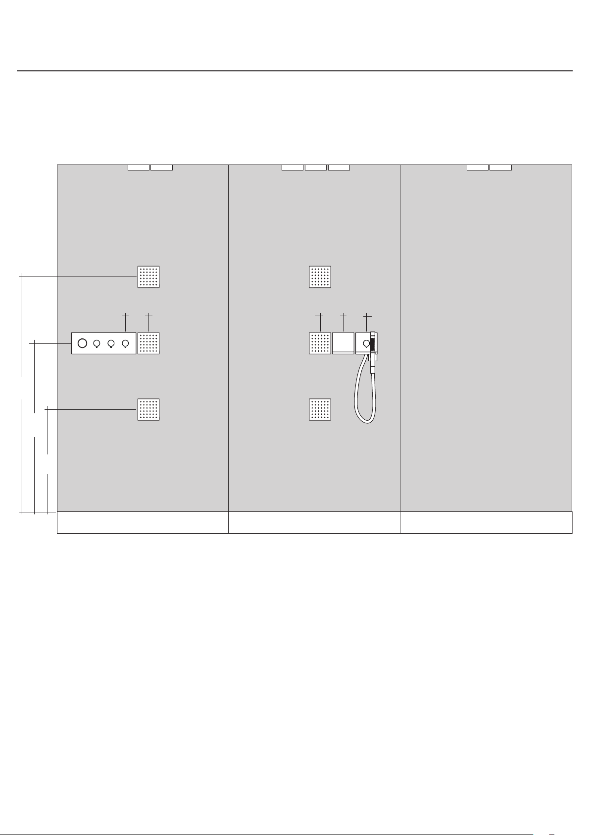
Installation Suggestions / Suggestions d'installation / Sugerencias para la instalación
55⅛"
5⅛"
5⅛"
5⅛"
39⅜"
23⅝"
11
Page 12
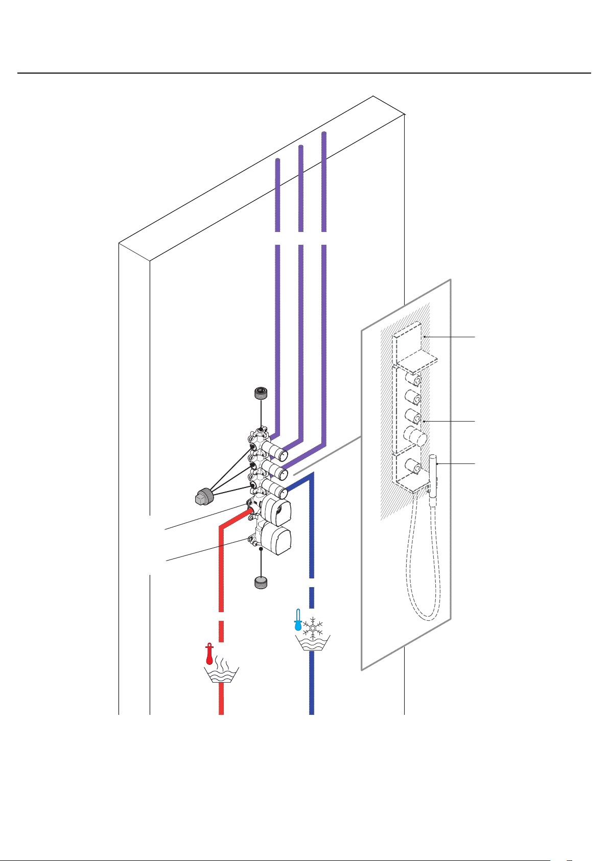
Installation Suggestions / Suggestions d'installation / Sugerencias para la instalación
Showerheaven
10625xx1
NPT ¾
40872xx0
10750181
10650181
10751xx1
10651xx1
NPT ¾
NPT ¾
12
Page 13
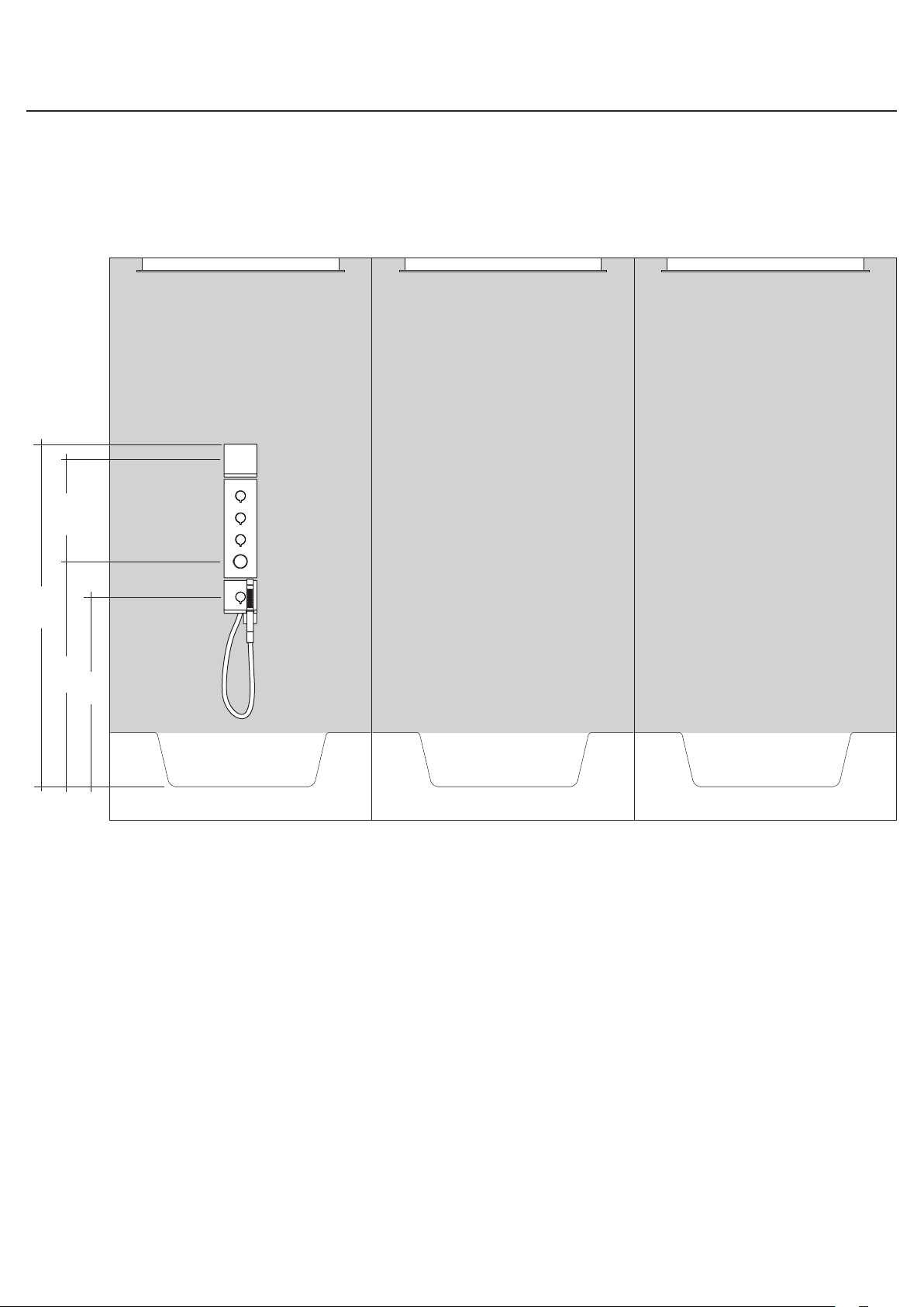
Installation Suggestions / Suggestions d'installation / Sugerencias para la instalación
60¼"
43¼" 14⅝"
38¼"
13
Page 14
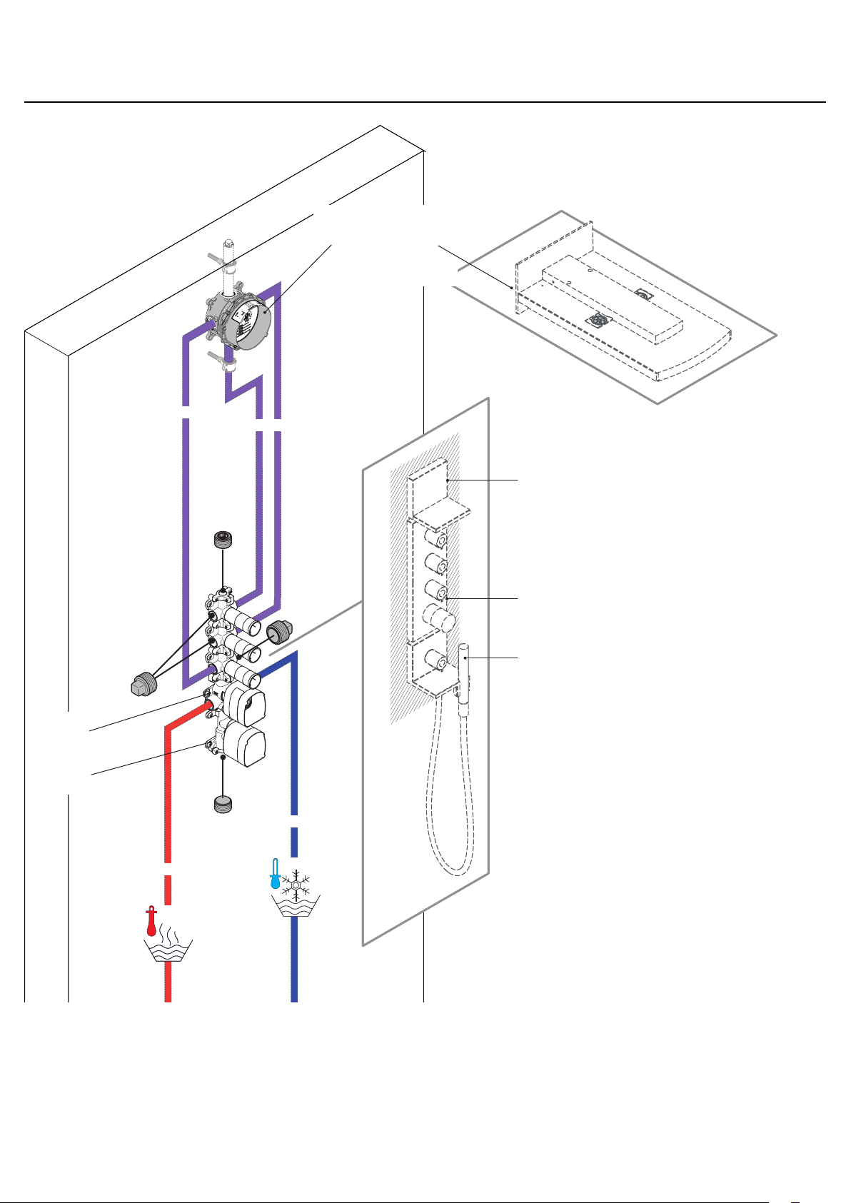
Installation Suggestions / Suggestions d'installation / Sugerencias para la instalación
iBox Universal
01850181
Rainfall 28411xx1
10750181
10650181
NPT ¾
NPT ¾
40872xx0
10751xx1
10651xx1
NPT ¾
14
NPT ¾
Page 15
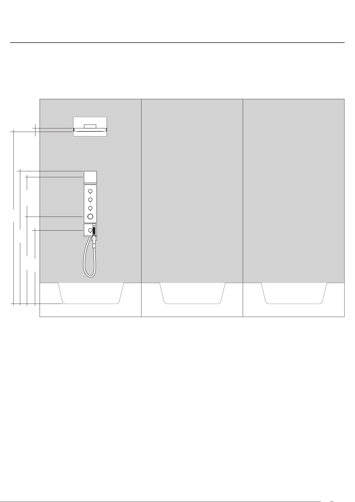
Installation Suggestions / Suggestions d'installation / Sugerencias para la instalación
1⅝"
14⅝"
84⅝"
53⅛"
43¼"
38¼"
15
Page 16
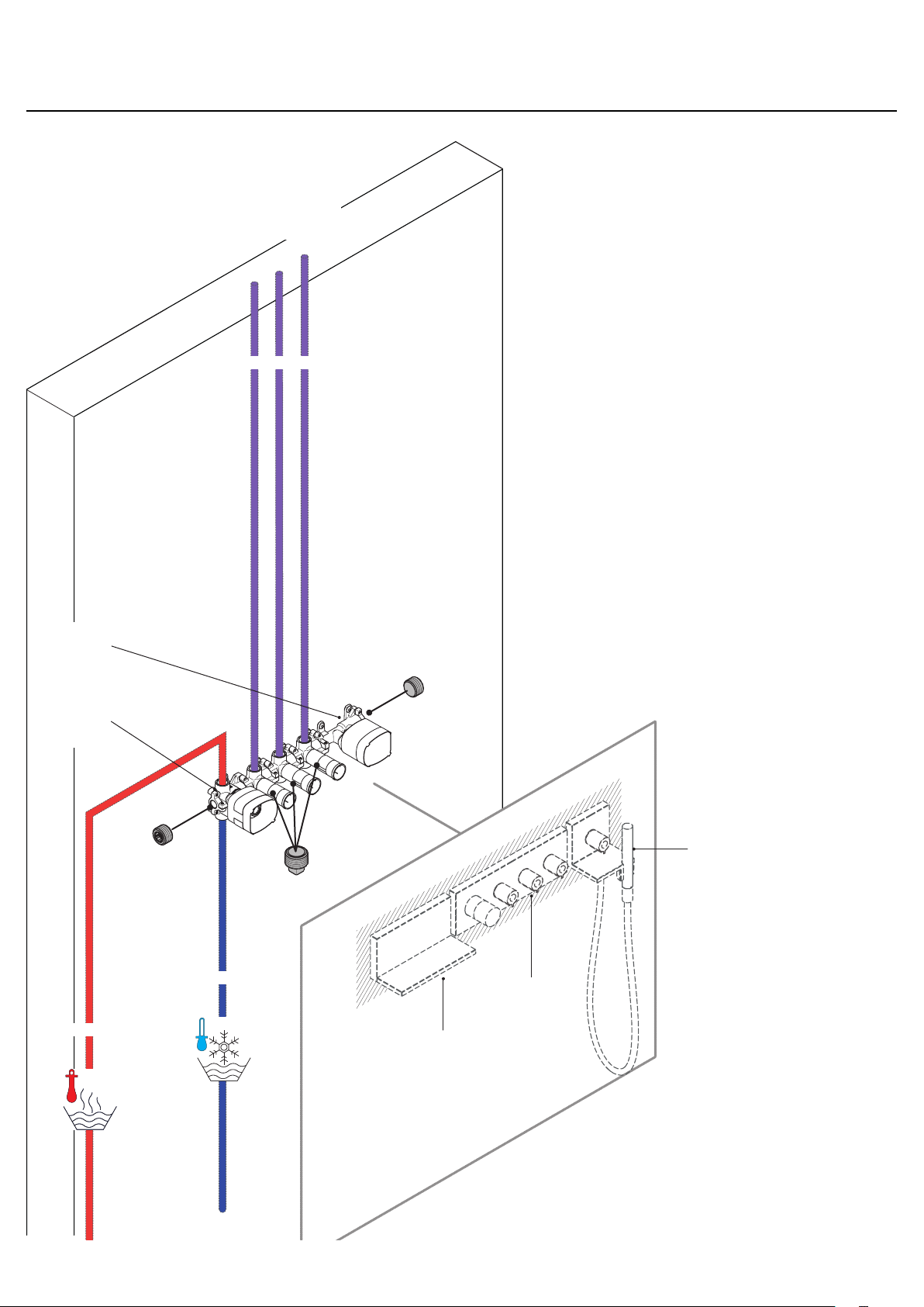
Installation Suggestions / Suggestions d'installation / Sugerencias para la instalación
Showerheaven
10625xx1
NPT ¾
10650181
10750181
NPT ¾
NPT ¾
10651xx1
10751xx1
40873xx0
16
Page 17
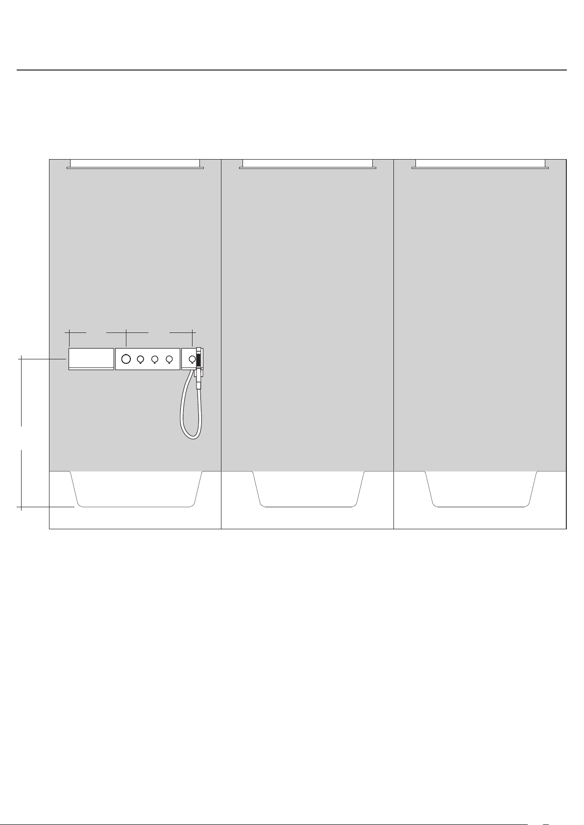
Installation Suggestions / Suggestions d'installation / Sugerencias para la instalación
39⅜"
12¼" 14⅝"
17
Page 18
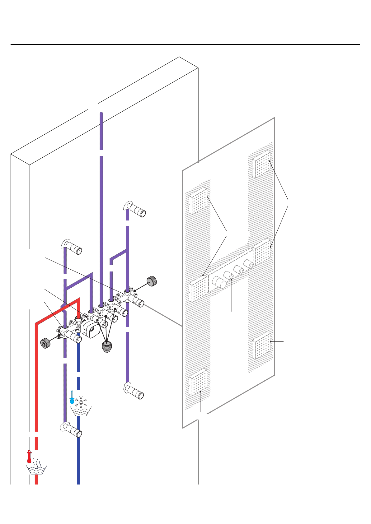
Installation Suggestions / Suggestions d'installation / Sugerencias para la instalación
28491xx1 (4x)
NPT ¾
28491xx1
28486181
10750181
28486181
NPT ½
28491xx1
NPT ¾
NPT ½
10751xx1
NPT ½
28491xx1
NPT ½
NPT ¾
18
28491xx1
NPT ¾
Page 19
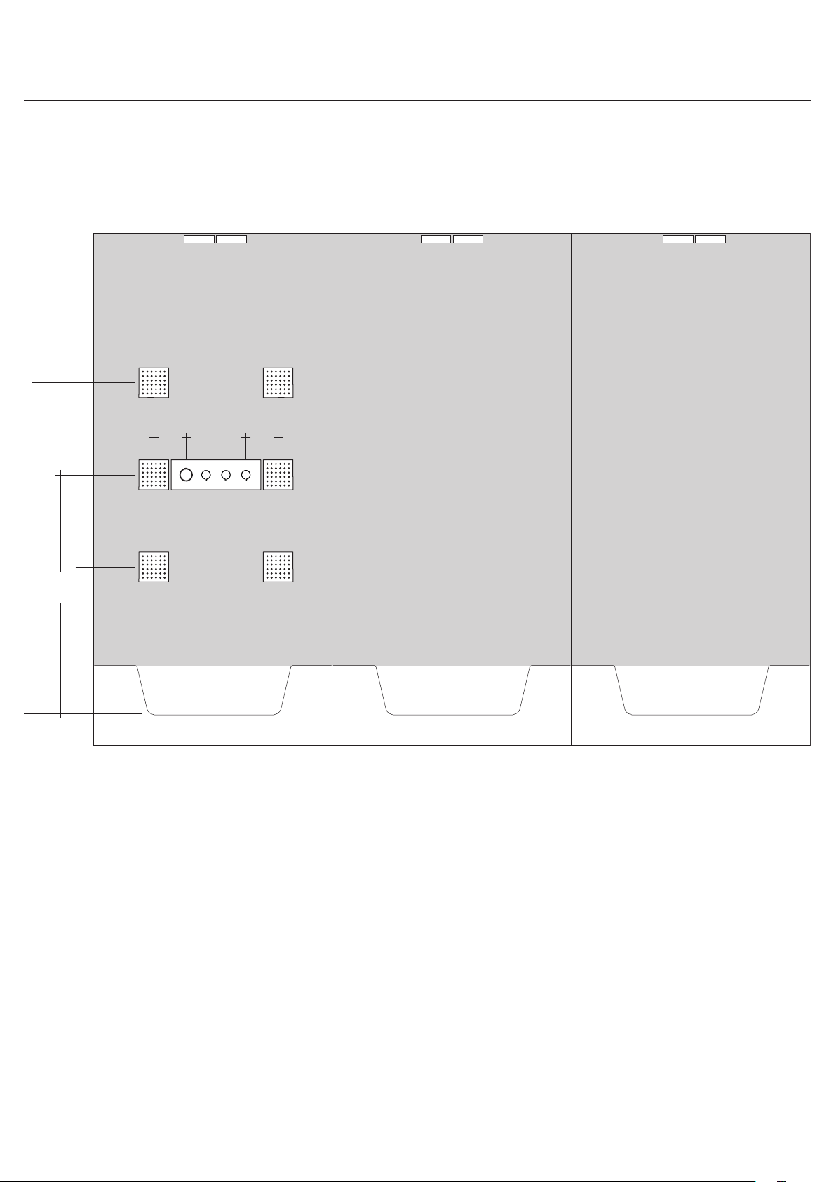
Installation Suggestions / Suggestions d'installation / Sugerencias para la instalación
19⅝"
5⅛"5⅛"
55⅛"
39⅜"
23⅝"
19
Page 20
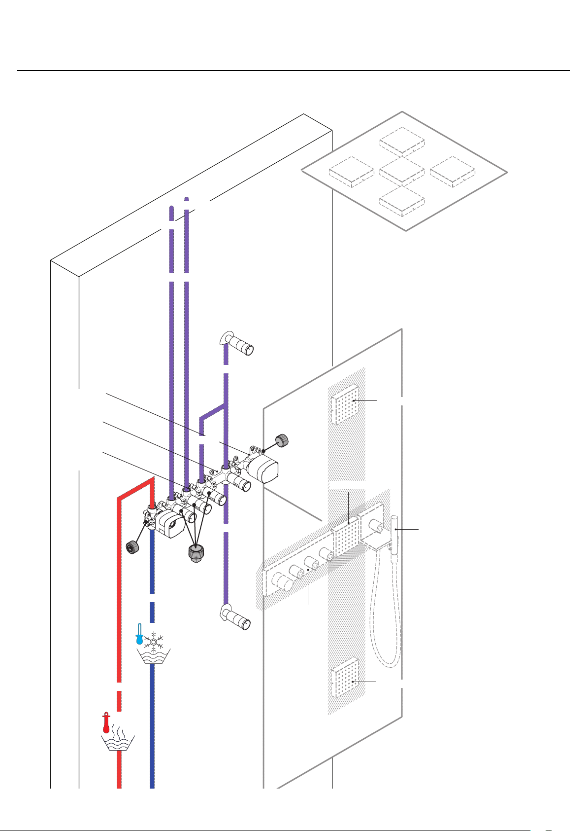
Installation Suggestions / Suggestions d'installation / Sugerencias para la instalación
28491xx1 (4x)
28491xx1 (1x)
NPT ¾
10650181
28486181
10750181
NPT ¾
NPT ½
NPT ½
NPT ½
28491xx1
28491xx1
10651xx1
10751xx1
20
NPT ¾
28491xx1
Page 21
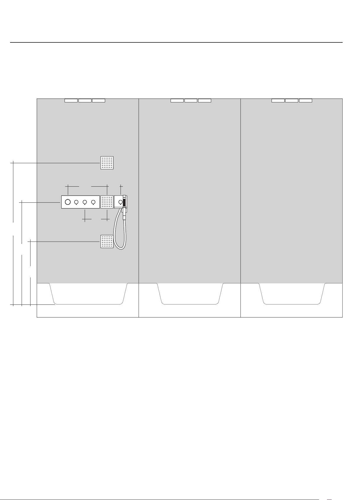
Installation Suggestions / Suggestions d'installation / Sugerencias para la instalación
55⅛"
39⅜"
23⅝"
14⅝"
5⅛"
8¼"
21
Page 22
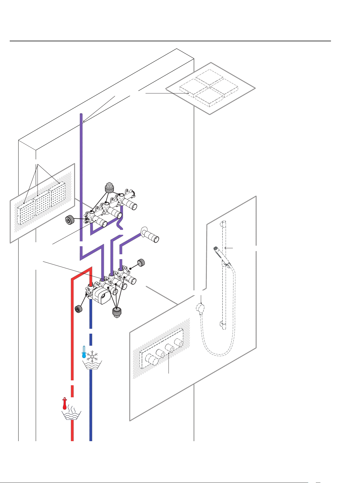
Installation Suggestions / Suggestions d'installation / Sugerencias para la instalación
28491xx1 (4x)
28491xx1
28486181 (3x)
10750181
NPT ½
NPT ¾
NPT ½
27980xx0
NPT ½
27458xx1
NPT ¾
10751xx1
22
Page 23
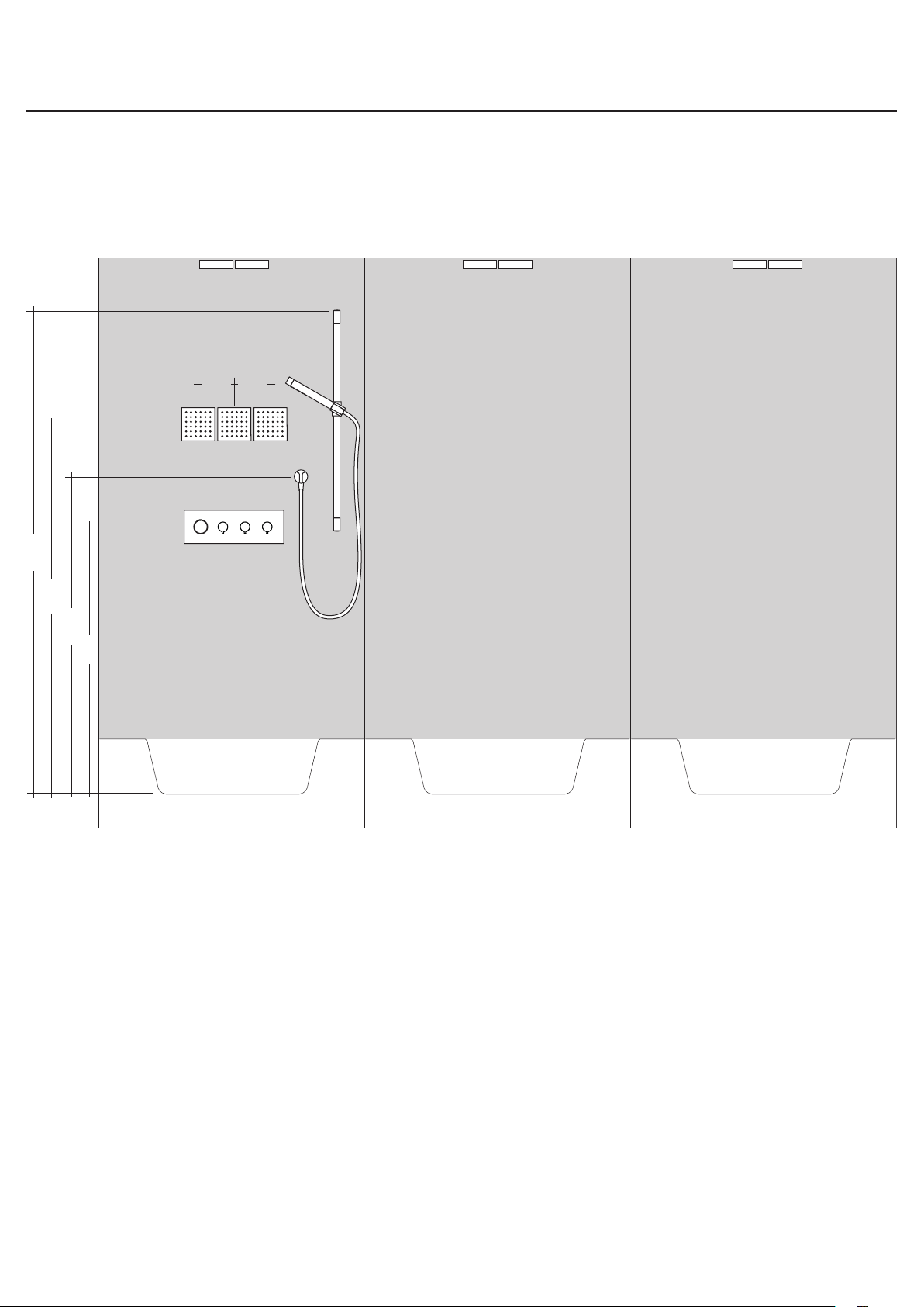
Installation Suggestions / Suggestions d'installation / Sugerencias para la instalación
84⅝"
5⅛" 5⅛"
55⅛"
47¼"
39⅜"
23
Page 24
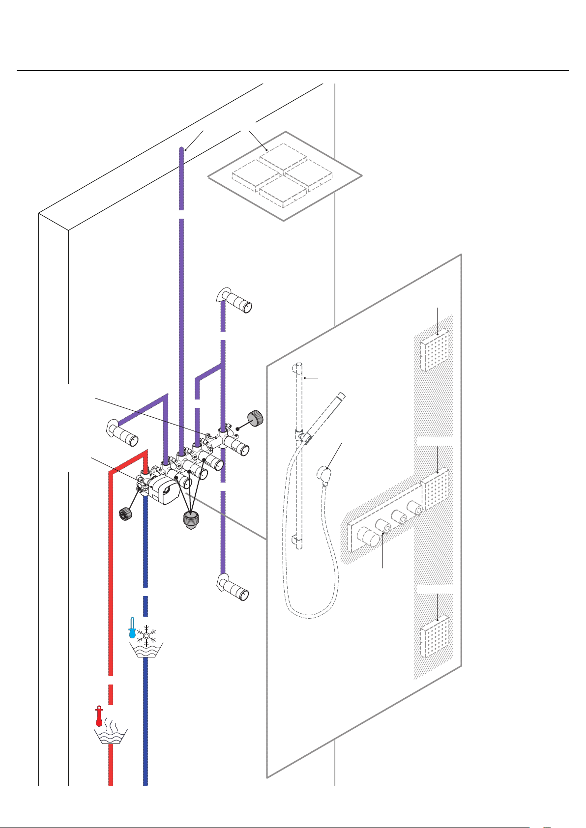
Installation Suggestions / Suggestions d'installation / Sugerencias para la instalación
28491xx1 (4x)
NPT ¾
28491xx1
NPT ½
28486181
10750181
NPT ¾
NPT ¾
NPT ½
27980xx0
27458xx1
28491xx1
10751xx1
28491xx1
24
NPT ¾
Page 25
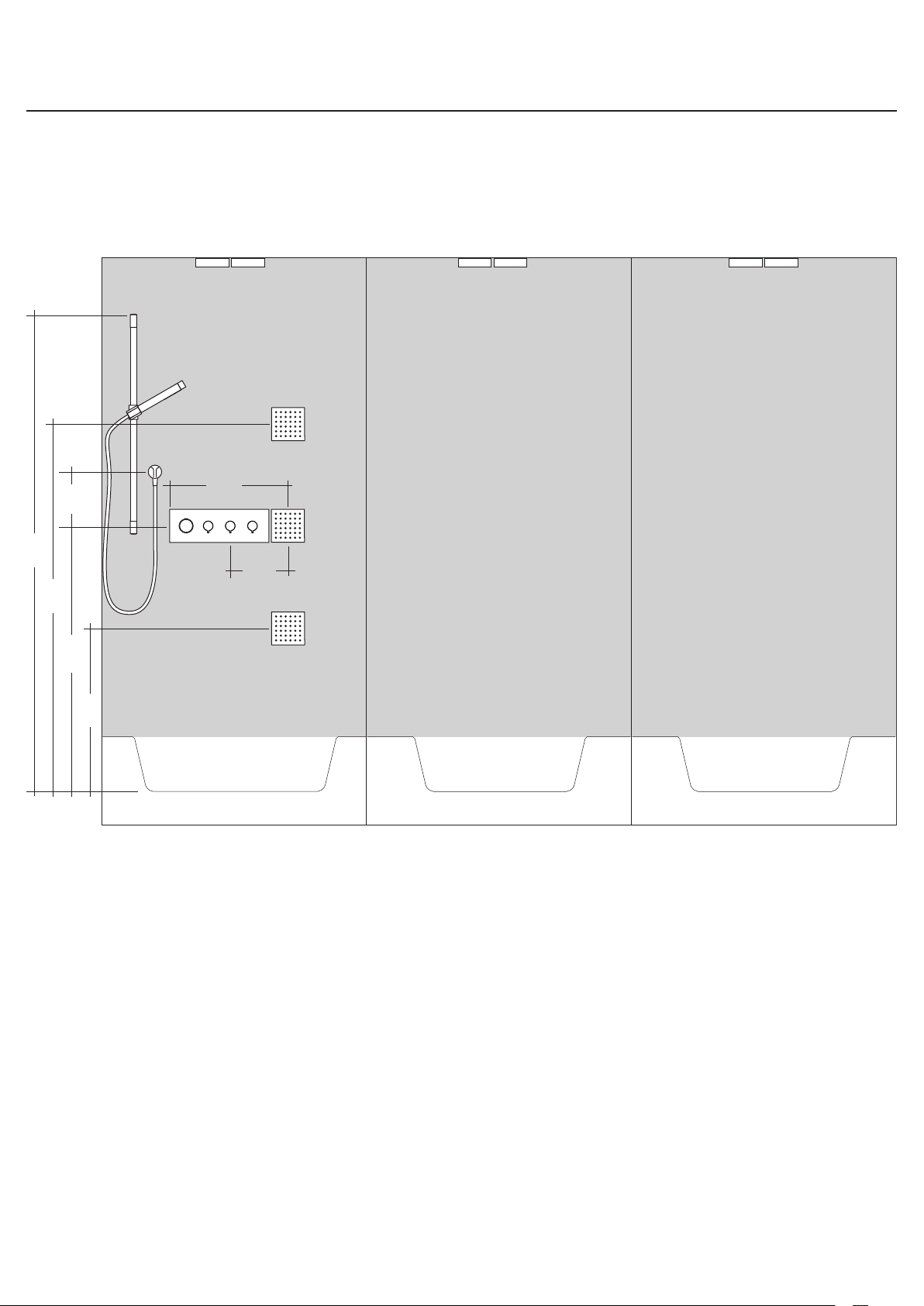
Installation Suggestions / Suggestions d'installation / Sugerencias para la instalación
16⅞"
7⅞"
84⅝"
8¼"
55⅛"
39⅜"
23⅝"
25
Page 26
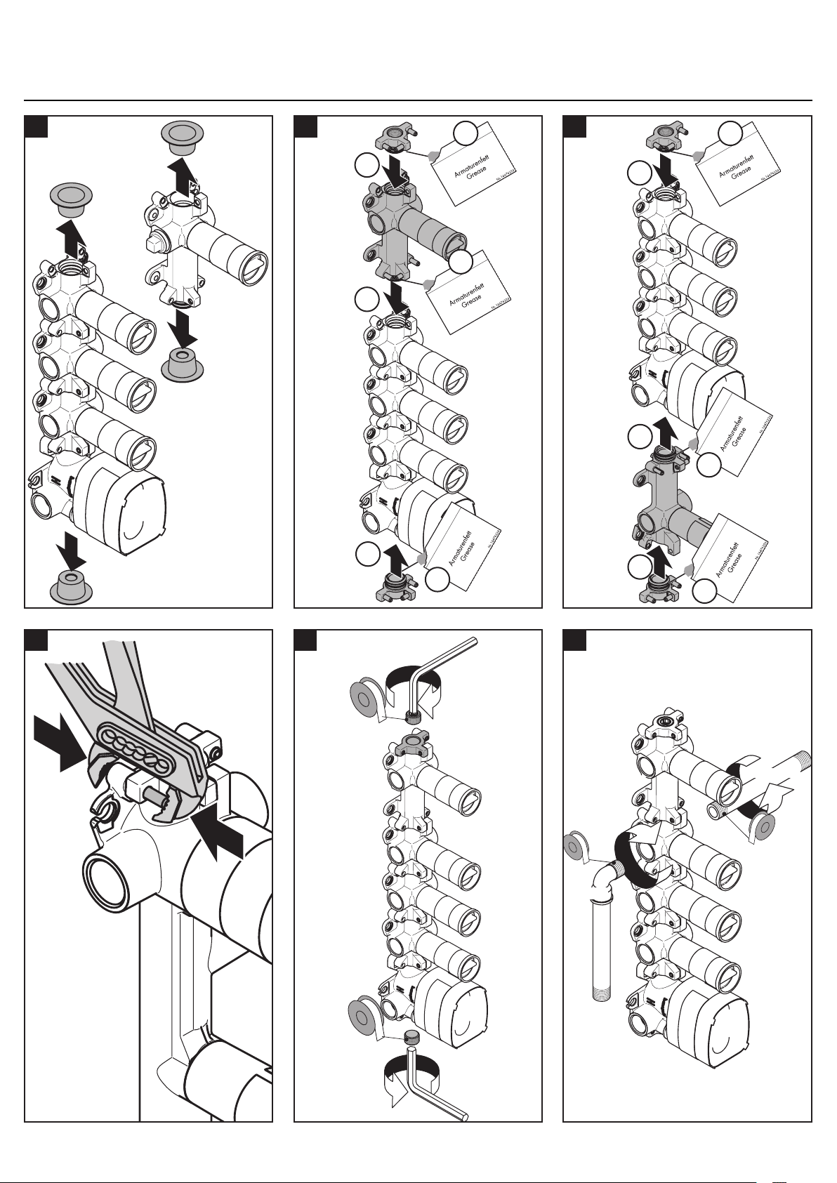
Installation / Installation / Instalación
Montage
1
2a 2b
4.
2.
3. 5.
1.
6.
2.
1.
6.
5.
3 4 5
12 mm
4.
3.
NPT ¾
NPT ¾
26
12 mm
Page 27
6
7
1.
3.
2.
10 mm
max.
min.
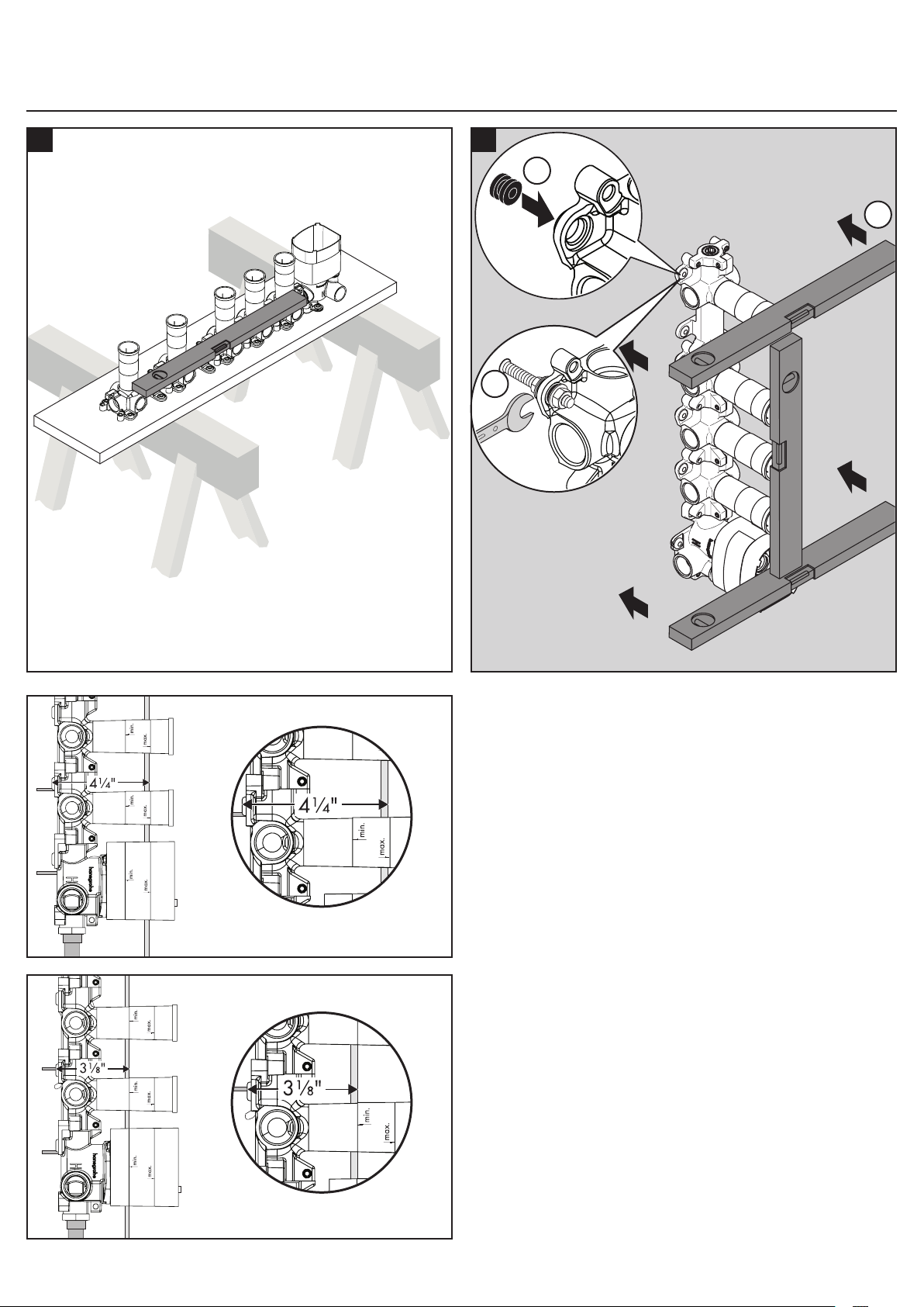
The outside surface of the finished wall must fall
between the "min" and "max" markings on the
plaster shields.
!
Installez le robinet de façon à ce que la surface
extérieure du mur fini se trouve entre les lignes «
minimum » et « maximum ».
!
Instale la válvula de modo que la superficie
exterior de la pared terminada quede entre las
marcas “min” y “max”.
!
27
Page 28
Starck
10650181
NPT ½
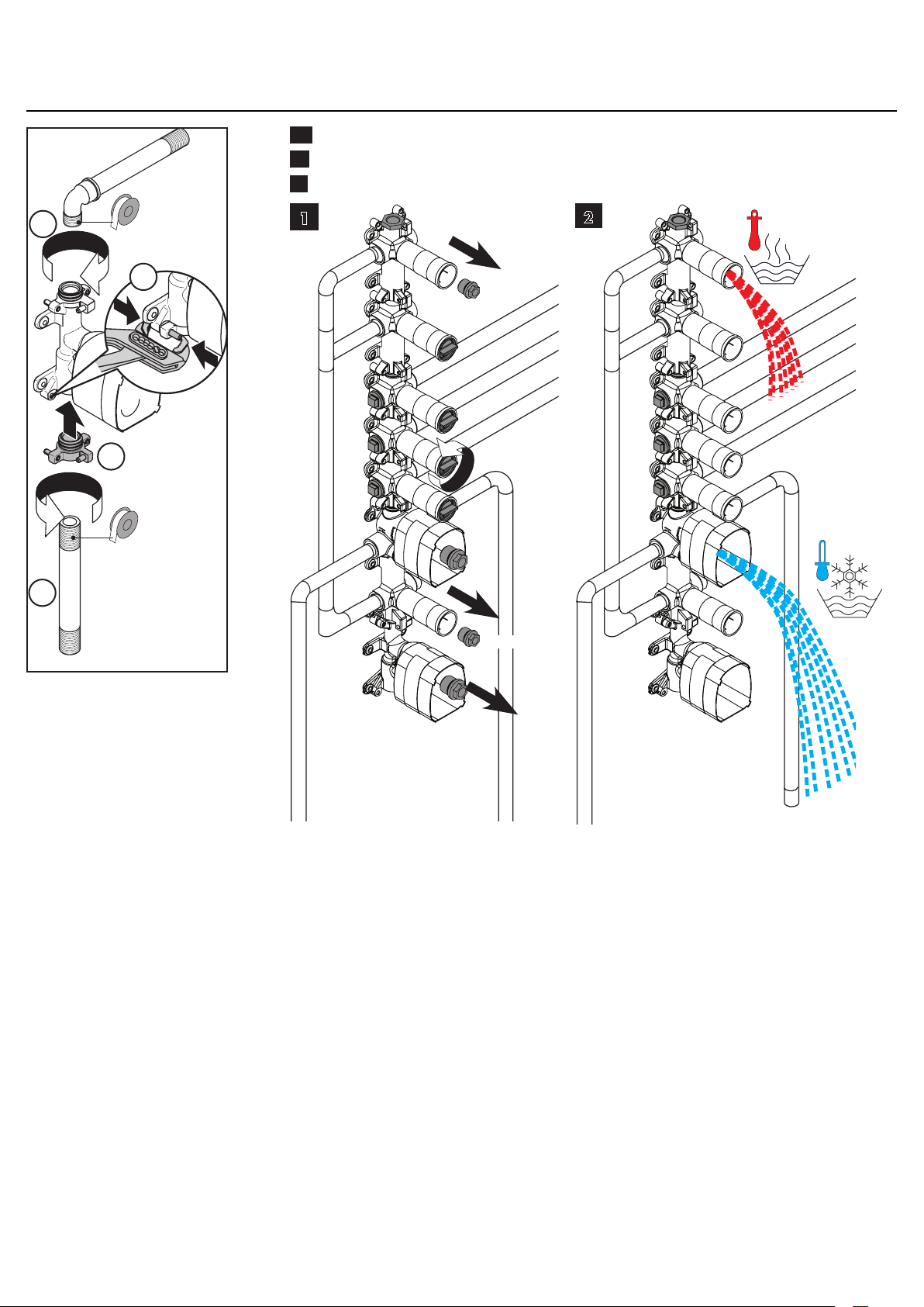
EN Flush the pipes.
FR Rincer les conduites
ES Limpiar lavando los conductos
3.
3.
1.
NPT ½
2.
1
17 mm
17 mm
2
!
28
Page 29
English Français Español
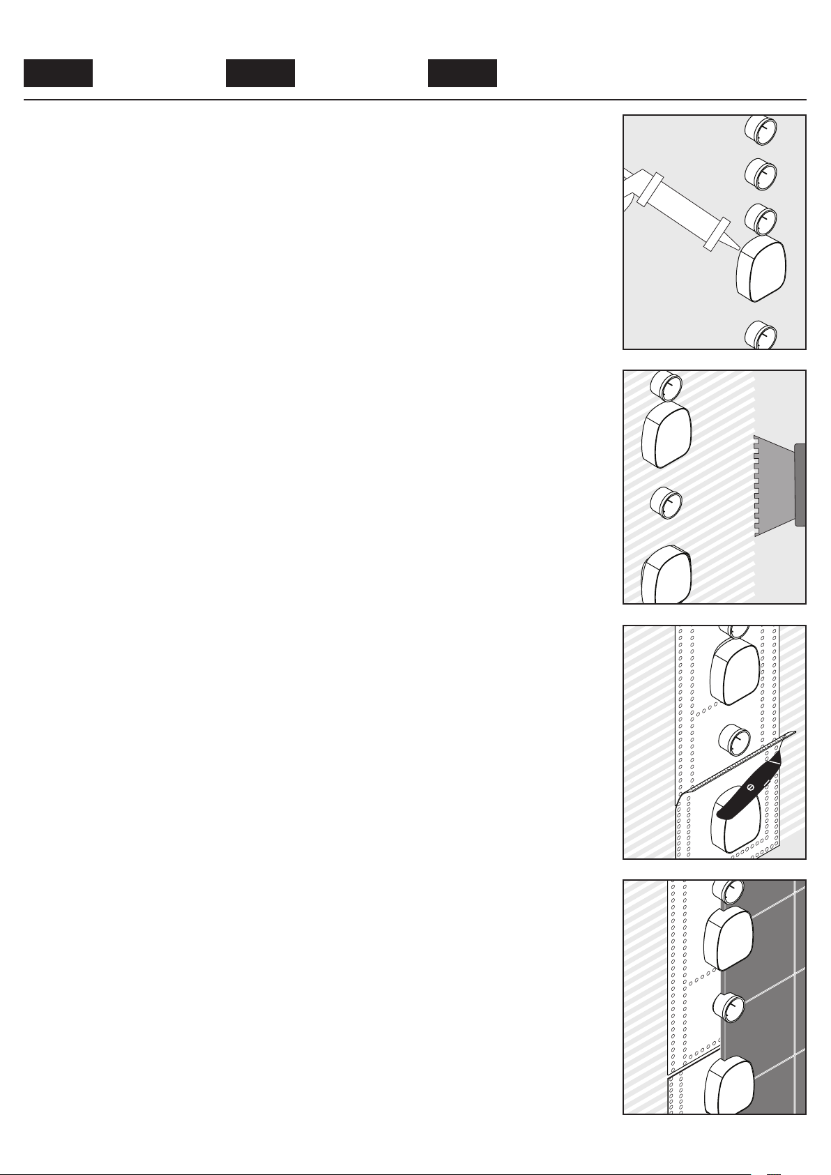
Install sheet rock or backer
board over the valves.
Seal the wall around the
plaster shields using waterproof sealant.
Brush adhesive (not included) over the backer board.
Do not use hot glue.
Installez le panneau d’appui
pour carrelage. Il doit atteindre les valves.
Scellez le mur autour de les
valves à l’aide d’un agent
d’étanchéité.
Appliquez un adhésif à
l’épreuve de l’eau (non inclus) sur le panneau d’appui,
autour de les valves.
N’utilisez pas de colle
chaude car vous pourriez
endommager le joint.
Instale el tablero de soporte de los azulejos. Debe
llegar hasta la caja de
instalación iBox.
Selle la pared alrededor de
las válvulas con un sellador
impermeable.
Aplique adhesivo (no
incluido) a la pared alrededor de las válvulas.
No use cola caliente,
puesto que daña la junta.
Install the sealing gasket(s).
Cut the sealing gasket to
size.
Do not allow the gaskets to
overlap.
Install the tile or other finished wall material over the
sealing gasket.
Installez le joint.
Couper les joints à la taille
voulue.
Les joints ne doivent pas se
chevaucher.
Installez les carreaux sur le
joint.
Instale la junta.
Cortar la junta de estanqueidad.
No deben sobreponerse las
juntas de estanqueidad.
Instale el azulejo sobre la
junta.
29
Page 30

30
Page 31

31
Page 32

Hansgrohe. Inc. • 1490 Bluegrass Lakes Parkway • Alpharetta. GA 30004
Tel. 770-360-9880 • Fax 770-360-9887
www.hansgrohe-usa.com
US - Installation Instructions • Part No. 90482922 • Revised 12/2014
 Loading...