

Page 1
Philippe Starck Two-Handle Tub Filler
Rough-In 10452181 Installation
Installation Considerations:
The 10458XX1 two-handle tub filler is designed to be installed with bathrooms
that will be fitted with water impervious flooring such as tile, marble, or
decorative stone.
A remote pressure balance valve, 13418181, is available for those areas that
require scald guard valves on tub fittings that include hand showers. It is
installed to the hot and cold water supplies within 6 of the tub filler.
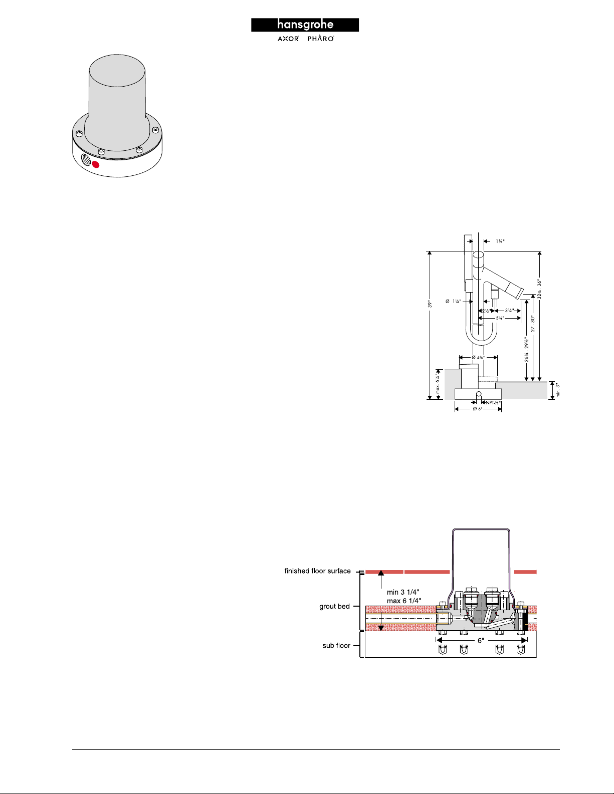
The 10452181 rough-in kit may be secured directly to concrete sub-flooring
using the supplied anchors. A three-inch minimum*, six-inch maximum* grout
bed must be laid over the completed rough-in assembly.
*THESE MINIMUM-MAXIMUM MEASURE-
MENTS ARE FOR THE GROUT BED ONLY.
THESE MEASUREMENTS ASSUME 1/4TILE
BE LAID OVER THE GROUT BED. FOR
WILL
THICKER THAN 1/4, SUBTRACT ANY
TILES
THICKNESS
THICKNESS
USED, THE MINIMUM GROUT BED THICKNESS
IS
WOULD
WOULD
SUBFLOOR
THICKNESS
OVER 1/4 FROM THE GROUT BED
. FOR EXAMPLE, IF 1/2 THICK TILE
BE 2 3/4 AND THE MAXIMUM
BE 5 3/4. MEASURING FROM THE
UP, THE MINIMUM OVERALL FLOOR
IS 3 1/4 AND THE MAXIMUM IS 6
1/4. SPECIAL CONSIDERATION WILL BE
NECESSARY
PORTION
ALLOW
MENTS
DURING THE FLOOR FRAMING
OF THE CONSTRUCTION PROCESS TO
FOR THESE FLOOR THICKNESS REQUIRE-
55
Installation
Page 2
Installation Instructions
• Apply plumbers thread sealing tape on two six-inch brass threaded pipe
nipples (not supplied) and tighten them into the brass rough-in flange.
Hot and cold connections will be made to these nipples.
• If the water connections are to be made below the floor, elbows can be
fitted to the brass nipples and turned down through the floor. The water
piping can be routed alternately along the surface of the sub-flooring if
desired.
• Note: It is important to have at least six inches of hot and cold piping
on top of the sub-flooring as it lends stability to the tub filler when
embedded in the grout floor. Strap all support piping to the sub-flooring.
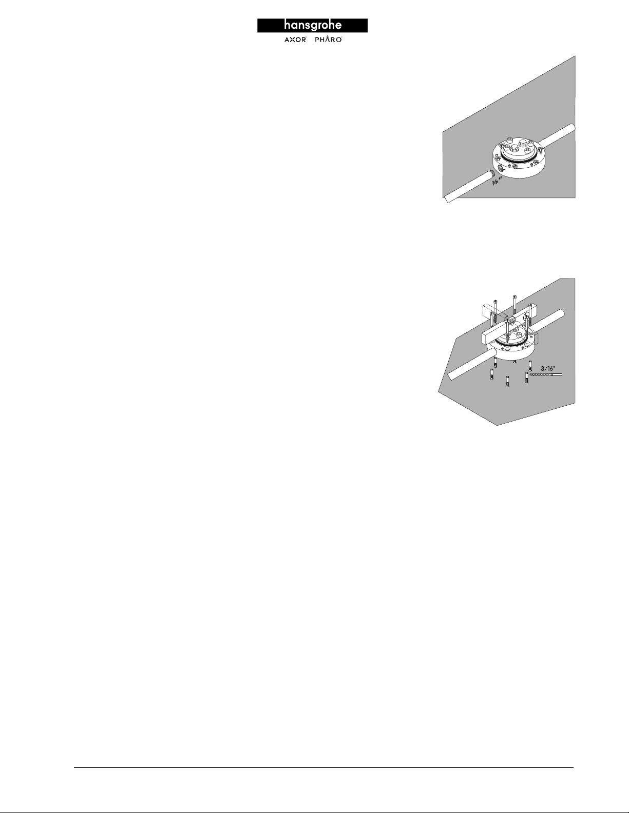
• Remove and set aside the six hex-head screws securing the black plastic
plaster guard from the brass rough-in flange. Position the brass rough-in
flange in the desired location of the two-handle tub mixer. Orient the
two water inlets to allow convenient connection to the hot and cold
supplies. Using the rough-in flange as a template, mark the six screw
holes using a 3/16 drill bit. Secure the rough-in flange to the floor
using the supplied lag screws.
• IMPORTANT: Make sure to keep the brass rough-in flange
level in all planes.
• The brass rough-in flange can also be through-bolted to the wood sub-
flooring, if desired (hardware not included).
• The same procedure is used for a concrete sub-floor, with the exception
that an eight-millimeter masonry drill bit is used for the screw holes. The
plastic masonry anchors (supplied) are inserted into the six screw holes
and the rough-in flange is secured to the concrete sub-floor using the
supplied screws. Once again, the flange must be level in all
planes, and grout and tile built up to the same dimensions over the
completed rough in, just as in a wood sub floor installation.
56
Installation
Page 3

• Make all water connections. Remove the two nylon plugs from the top of
the white nylon test cover on the brass rough-in flange, and screw hose
bibbs into the threaded openings. Pressurize the piping system and check
for leaks. Attach a hose to the hose bibbs and thoroughly flush the hot
and cold piping of all debris.
• Depressurize and drain the piping system. Remove the hose bibbs and
reinstall the nylon plugs into the top of the white nylon test cover. Repressurize the system and check all connections for leaks.
• Reinstall the black plastic plaster guard onto the brass rough-in flange
using the hex-head screws.
• Finish flooring can now be completed. The outside surface of the finished
floor MUST fall somewhere between the minimum and maximum
markings on the shield. Rough-in is now complete.
57
Installation
Page 4

Philippe Starck Two-Handle Tub Filler
Trim Kit 10458XX1 Installation
Installation Considerations
Rough-in 10452181 must be installed, and the finished
floor must be complete before installing this trim kit.
Installation Instructions
• Cut off the black plastic plaster guard 3/8 above the finished
floor. Depressurize and drain down the piping system.
• Remove the four hex-head screws that secure the white nylon test
cover to the brass rough-in flange. Put the screws in a safe
place - they will be re-used. Lift the test cover off. The test
cover may be discarded. Make sure not to allow any debris to
fall onto the brass rough-in flange.
• Carefully lower the two-handle tub filler onto the brass rough-in
flange and gently twist it to firmly seat the o-ring seals into their
receiver in the brass flange. Make sure the tub filler is plumb in
the vertical plane. After making sure the tub filler spout is oriented
in the desired direction, tighten the six hex-head screws (supplied)
to secure the tub filler to the rough-in flange. All screws should be
hand tightened, and then tightened one turn at a time beginning
with one screw and then tightening the screw on the opposite side
an equal amount. Follow this procedure until all screws are firmly
and equally tightened.
• Re-check the vertical plumb of the tub filler.
58
Installation
Page 5

• Connect the handshower head and hose to the tub
filler using the supplied rubber gaskets. Turn on the
water supply and check for leaks.
• Seal the juncture of the plaster guard and the finished
floor with a compatible, non-staining waterproof
sealant.
• After ensuring that the two-handle tub filler installation
is performing properly, lower the decorative floor
flange to the finished floor.
User Instructions
The right handle controls the cold water, the left handle
controls the hot water.
When the unit is first turned on, water will come from the
spout. Pull on the end of the spout to divert to the
handshower. When the water is turned off, the unit will
automatically reset to the spout. NOTE: DO NOT DIVERT
TO THE HANDSHOWER UNLESS IT IS POSITIONED OVER THE TUB.
WATER
To remove the handhshower from the holder, pull up until
the hose nut clears the holder, then pull out. Reverse the
process to put the handshower back into the holder.
The handshower uses the RubitTM cleaning system. To
dislodge any scale deposits from the spray channels, turn
the water on lightly and rub the spray channels gently
with your finger or a sponge.
59
Installation
 Loading...