


INDEX
POS 5000

-2-
CONTENTS
Chapter 1. Introduction
Chapter 3. BIOS Setup Utility
Chapter 5. Motherboard
1-1. Warranty ………………………………………………….
3
3-1. BIOS Setup Program …………………………………..
35
5-1. Motherboard Layout ………..……...…………………….………
61
1-2. Copyright ………………………………….……………..
4
3-2. BIOS Menu Screen …...……………………………...…
37
5-2. Motherboard DIP Switch & Interface ……………………
63
1-3. Safety Information ...…….………………………….
4
3-3. Standard CMOS Features ...………………………...
38
5-3. Serial Port Power Jumper Settings …..….………………...
65
1-4. Liability Limitation …………….…………………….
5
3-4. Advanced BIOS Features ……………………………
40
5-4. Clearing CMOS …………………………………………..…..………
66
1-5. Installation Recommendations ……………….
7
3-5. Advanced Chipset Features ……………..………...
42
3-6. Integrated Peripherals ………………………………..
44
Chapter 6. Maintenance
Chapter 2. Product Overview
3-7. Power Management Setup ……………………......
49
6-1. Safety Warning ……………………………………………….………
67
2-1. Inside Your Package ………………………………..
8
3-8. PnP/PCI Configurations …………………………..….
51
- Removing Interface Panel ………..………………………………..
68
2-2. Pre-installation Preparation ...………………….
12
3-9. PC Health Status ……………...…………………………
52
- Motherboard Replacement ……………………………………….
69
2-3. Product Outline .……………………………………...
12
3-10. Load Setup Defaults …...…….……………………...
53
- Fan/Heatsink Replacement …………..…………………..……….
72
2-4. Installation of Optional Devices ……………..
17
3-11. Save Password …...…………………………..…………
54
- HDD Replacement …..………………………………...………………
74
- CDP Installation ……………………………………………
17
3-12. Save & Exit Setup …...………..………………………
55
- Power Supply Unit (PSU) Replacement …………………....
76
- 2nd Display Installation ……………………………….
18
3-13. Exit Without Saving ………………………………….
56
- MSR Replacement .…………………………………….………………
78
- Keyboard & Mouse Connection ….…..………….
19
- CPU Replacement .……………………………………..………………
79
- Connection via USB Port ……………………….........
20
Chapter 4. Troubleshooting
- Memory (RAM) Replacement ……………………………………
80
- Connection via Ethernet Port (LAN) ……….…..
21
4-1. Network Issues …………………………..……………….
57
- Display Unit Replacement …….…….……………………………
81
- Speaker & Microphone Connection …..…..…...
22
4-2. MSR Issues ……………………….…………………………
57
- Installing New Paper Roll ……...…………………………………..
84
- Cash Drawer Connection ……………………..……...
23
4-3. USB Issues …….…………………………………………….
58
- Paper Jam Correction …….………………………………………….
86
- Power Cable Connection ..…..…………………........
24
4-4. LCD Issues ……………..……………………………………
58
- Printer Roller & Bracket Replacement ……………………..
88
2-5. Basic Operations ……………………………………….
25
4-5. Touch-screen Issues ………………………..…………
58
- Printer Mechanism & Circuit Board Replacement ……
90
- Integrated Printer: Control Panel ..……..………..
27
4-6. Power Issues ……………………………………..………..
59
6-2. Upgrade and Power Supply Specifications …………...
94
- Integrated Printer: Self-test ………...……..………..
28
4-7. PS/2 Keyboard Issues …………………………..........
59
6-3. Technical Specifications (IMPREX_M) …………………….
95
- Integrated Printer: DIP Switch ……………....…….
29
4-8. Booting Issues ………………………………….....……..
59
2-6. System Drivers ………………….……………………….
34
4-9. Printer Issues ……………………………………...……....
60

-3-
POS 5000 SYSTEM
Chapter 1. Introduction
1-1. Warranty
We guarantee our POS terminal product and its parts against defects in materials and workmanship, under proper use, for a standard period of
2 years from the original date of purchase.
During this period, we will repair or replace defective and/or faulty products or parts without charge to the customer for parts and labor.
The 1st year includes servicing and new or refurbished replacement parts free of charge, with one-way shipping costs borne by the seller. The
customer shall, however, be responsible for the return delivery costs.
The 2nd year also includes free of charge servicing and parts, but a limited warranty requires the entire shipping cost to be borne by the
customer.
Products out of the warranty period or scope shall be diagnosed at the customer's expense.
In the case of product damage due to error on part of the consumer, incorrect usage, carelessness or natural phenomenon, the customer shall
bear the full cost for both repair and delivery.

-4-
1-2. Copyright
This publication, including all photographs, illustrations and software, is protected under international copyright law with all rights reserved to the
manufacturer. Neither this manual, nor any of the material contained herein, may be reproduced without express written consent of the author.
1-3. Safety Information
1. Always ensure that the correct power voltage is used as a precaution against fire and electrical shock.
2. Avoid exposing product to direct sunlight. Do not use product in areas of high humidity.
Doing so may cause low reliability and/or operational malfunction.
3. Be careful of static electricity on PCB of system with anti-static appliances. Doing so may cause inferior reliability and shorted product life.
4. Keep product away from highly static areas. This may lead to inferior performance and reduced life cycle.
5. Do not interfere with, or obstruct metal components inside product. Doing so may cause the risk of fire or electric shock.
6. Do not pull on power cable or peripheral devices‟ connector cable. Doing so may cause fire, electric shock or electronic system malfunction.
7. Use caution when around other electronic devices with possible high frequency or electro-magnetic effects e.g. Audio, Electronic-range etc.
Doing so will lead to the serious risk of product malfunctioning or a system error occurring.
8. Ensure that batteries are replaced correctly. Failure to do this may result in sudden explosions.
9. Dispose of used batteries properly according to the instructions.

-5-
1-4. Liability Limitation
● Installation and maintenance
We recommend that you inquire about product installation, maintenance and repair service from the official service center and agent office.
POSBANK takes no responsibility for malfunctions or system errors occurring after service and/or system check carried out by unofficial service providers.
● High frequency appliances
This product is qualified by FCC, CE, EMI and MIC compliances, and is thus governed by these qualifications‟ safety regulations.
However, the product can affect and be affected by other high frequencies generated around it. As such, POSBANK does not consider liability for any system
error or disorder due to this issue.
● Electronic noise emitting equipment
We recommend using the product away from electronic noise emitting equipment such as heaters, motors, fluorescent lights, TVs etc. as it may cause
interruption or interference with normal operation.
● Installation location
For optimal performance, the product should be kept in an environment of lower than 65% humidity and in a temperature of 10 ~ 30℃. Please also keep
away from direct sun-light.

-6-
● Cleaning procedure
Cleaning with chemical based products (in particular those containing benzyl or chemical thinning agents) can damage the exterior surfaces of the product.
We recommend using a soft damp cloth and wiping gently, taking particular care when dealing with the LCD display screen.
● Product limitations
1. The use of this product for anything other than POS tasks is strictly prohibited.
The product is not supported for regular PC and interface operation.
2. This product is for business use only, and not for usage in the home.
3. Both hardware and software are both fully configured.
4. Normal operating is guaranteed on a steady power connection.

-7-
1-5. Installation Recommendations
1. Avoid installing during thunderstorms. (Possibility of dangerous exposure to electricity.)
2. Install away from damp spaces or water-leaks.
3. Beware of static occurrence during installation.
4. Use only ground connected and quality certified power cords and cables.
5. Keep out of direct sun-light, extremely high or low temperatures, or high humidity areas.
6. Install product away from areas prone to shocks or vibration.
7. Install product away from sewing machines, welding equipment, electric stoves, audio equipment and other high frequency generating
equipment.
8. Installation and use in close proximity to an air-conditioning unit is not recommended.
9. Do not connect cables underneath carpets or floorboards.
10. Only use power cables supplied by pre-approved and certified venders.
11. Never use power cords from high power source appliances.
e.g. Electronic heaters, Electric stoves, Audio equipment, Air-conditioners, Refrigerators etc.
12. The use of multiple connections in a shared power outlet/socket is not recommended.

-8-
POS 5000
Chapter 2. Product overview
2-1. Inside Your Package
1. Please check your package and confirm its contents.
2. The POS terminal main unit, power cable, user manual and driver CD are included in the package. If any items are missing or damaged,
please contact your dealer for assistance.
» All user manuals and drivers are available for download on our website: www.posbank.com.

-9-
[Package Contents]
User manual Power cable
Driver CD Roll paper
IMPREX_P main unit
-10-
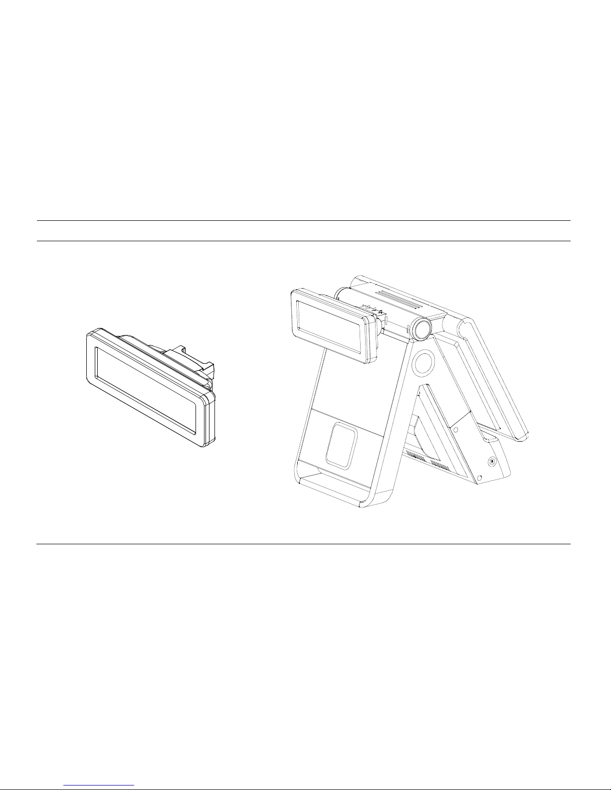
[Optional: Customer Display (CDP)]

-11-
[Optional: 2nd Display (12inch LCD Monitor)]

-12-
2-2. Pre-installation Preparation
1. Remove protective film from touch-screen to prevent possible operating difficulties.
2. Attach all optional parts before setting up the main POS unit.
2-3. Product Outline
- Each part of product may differ depending on the specific POS model.
- Model-specific data sheets are provided on our website at www.posbank.com.

-13-
[Front View (Display Unit Down)]
LCD & TOUCH
PANEL DISPLAY
POWER BUTTON
INTERNAL RECEIPT PRINTER
MAGNETIC STRIPE READER
(MSR)
POWER LED
HDD LED
LAN LED
SMART CARD READER
(SCR)

-14-
[Front View (Display Unit Up)]
LCD & TOUCH
PANEL DISPLAY
PRINTER COVER
OPEN BUTTON
PAPER FEED BUTTON
INTERNAL RECEIPT PRINTER
COVER
PAPER OUT LED

-15-
[Rear/Underside View]
CUSTOMER DISPLAY
(CDP) –
optional
RUBBER FOOT
DISPLAY HINGE
MOBILE PAYMENT MODULE
-
optional
EXT USB
PARALLEL PORT
-
optional

-16-
[Power & I/O port]
Description
Description
1
AC-IN power socket
5
Cash drawer port
2
PS/2 mouse port
6
USB port
3
PS/2 keyboard port
7
Ethernet port (LAN)
4
COM1, COM2, COM3 port
8
VGA/Monitor port (optional)
6 5
7 8
3 1
4 2

-17-
2-4. Installation of Optional Devices
[CDP Installation] Warning: Completely remove power cable when opening main unit or installing optional devices.
1. Connect CPD cable to main unit.
2. Insert CDP into slot on main unit.
3. Firmly attach using the 3 screws
provided.
CDP installation is successful if the default
text appears on CDP when powering on the
POS system.

-18-
[2nd Display Installation] Warning: Completely remove power cable when opening main unit or installing optional devices.
1. Connect CPD cable to main unit.
2. Insert 2nd display into slot on main
unit.
3. Firmly attach using the 3 screws
provided.
The unit is successfully installed if the O/S boots
on the 2nd display unit.

-19-
[Keyboard & Mouse Connection]
1. Keyboard connection: PS/2 type keyboard.
2. Mouse connection: PS/2 type mouse.

-20-
[Connection via USB Port]
Four USB ports are provided in the POS unit, two at the rear I/O and two at the side, all of which support the standard USB 2.0.
Some USB devices (optional devices) are only functional with specific driver software installed.
If multiple USB devices are used together, this may result in abnormal functionality.
Using a USB hub with external adapter for supplying power is recommended.
Dependent on the type of device, it is possible for the USB device to be recognized later than normal.

-21-
[Connection via Ethernet Port (LAN)]
The Ethernet port located at the rear I/O supports 10/100/1000Mbps using an RJ45 connector cable.
When connected properly, the LAN LED light will be switched on.

-22-
[Speaker & Microphone Connection]
1. Speaker connection
2. Microphone connection

-23-
[Cash Drawer Connection]
The cash drawer port (RJ11) is located at the rear I/O, and supports 24V Solenoid type.
The cash drawer port is connected to the internal printer on the mother board. The POS will not operate properly if no printer is attached to
the POS. If this is the case, connect cash drawer to external printer port.

-24-
[Power Cable Connection]
Connect power cable to AC power socket at rear of POS main unit (as shown above)
The IMPREX_M POS terminal supports 110V ~ 220V power voltage.

-25-
2-5. Basic Operations
[Switching On POS]
» NB: Switch on all peripheral units prior to powering on POS main unit.
1. Press POWER button on the POS unit. (POWER LED will light up.)
2. Confirm that Windows loads correctly.
Power Switch

-26-
[Shutting Down POS]
For product stability, we recommend closing Windows from the O/S. Please make sure that you have closed all applications before closing Windows.
* Alternatively, you may shut down Windows by simply pressing the „Power‟ switch on the Main Unit.
1. Click „Start‟ and select „Turn off Computer‟ 2. Click „Shut Down‟ to close Windows.

-27-
[Integrated Printer: Control Panel]
OPEN (Button):
Press to open integrated printer.
PAPER FEED (Button): Pressing once discharges a short
load of paper. Holding down continuously will discharge
paper until the button is released again.
PAPER OUT (LED):
This LED will light up while printing.

-28-
[Integrated Printer: Self-test]
1. Ensure the paper roll is installed correctly.
2. While holding down the FEED button, turn on the power to
begin the self-test.
3. The self-test prints out the current ROM version and DIP
switch settings.
4. Release the FEED button when self-test is finished.
5. The printer is ready to resume normal operation upon
completion of the self-test.

-29-
[Integrated Printer: DIP Switch]
Remove cover to locate
printer DIP switch

-30-
[Switch 1 - Settings]
No
Function
Setting
Default
1
RS232-C
(Transmission
speed)
SW1-1
SW1-2
SW1-3
9600 BPS
2400 BPS
OFF
OFF
OFF
4800 BPS
ON
OFF
OFF
9600 BPS
OFF
ON
OFF
19200 BPS
ON
ON
OFF
38400 BPS
OFF
OFF
ON
57600 BPS
ON
OFF
ON
115200 BPS
OFF
ON
ON
2
RS232-C
(Handshaking)
SW1-4
DTR/DSR
DTR/DSR
OFF
XON/XOFF
ON
3
Auto
cutter
SW2-7
Enable
Enable
OFF
Disable
ON
4
Sound
SW1-5
SW1-6
No Sound
No Sound
OFF
OFF
Internal buzzer
ON
OFF
External buzzer
OFF
ON
Voice
ON
ON

-31-
No
Function
Setting
Default
5
Print density
SW1-7
SW1-8
Low
Low power
OFF
OFF
Normal
ON
OFF
Slightly
OFF
ON
Dark
ON
ON
6
Auto cutter
function
SW2-8
Partial cut
Partial cut
OFF
Full cut
ON

-32-
[Switch 2 - Settings]
No.
Language
Code page
Default setting : English
SW2-6
SW2-5
SW2-4
SW2-3
SW2-2
SW2-1
1
USA, Standard Europe
CP-437
OFF
OFF
OFF
OFF
OFF
OFF
2
Japanese
Katakana
OFF
OFF
OFF
OFF
OFF
ON
3
Multilingual
CP-850
OFF
OFF
OFF
OFF
ON
OFF
4
Portuguese
CP-860
OFF
OFF
OFF
OFF
ON
ON
5
Canadian-French
CP-863
OFF
OFF
OFF
ON
OFF
OFF
6
Nordic
CP-865
OFF
OFF
OFF
ON
OFF
ON
7
Latin I
CP-1252
OFF
OFF
OFF
ON
ON
OFF
8
Cyrillic Russian
CP-866
OFF
OFF
OFF
ON
ON
ON
9
Latin II
CP-852
OFF
OFF
ON
OFF
OFF
OFF
10
Euro
CP-858
OFF
OFF
ON
OFF
OFF
ON
11
Thailand character
Thai-42
OFF
OFF
ON
OFF
ON
OFF
12
Thai-11
OFF
OFF
ON
OFF
ON
ON
13
Thai-14
OFF
OFF
ON
ON
OFF
OFF
14
Thai-16
OFF
OFF
ON
ON
OFF
ON
15
Thai-18
OFF
OFF
ON
ON
ON
OFF
16
CP-874
OFF
OFF
ON
ON
ON
ON
17
Greek
CP-737
OFF
ON
OFF
OFF
OFF
OFF
18
Baltic
CP-775
OFF
ON
OFF
OFF
OFF
ON
19
Cyrillic
CP-855
OFF
ON
OFF
OFF
ON
OFF
20
Turkish
CP-857
OFF
ON
OFF
OFF
ON
ON
21
Icelandic
CP-861
OFF
ON
OFF
ON
OFF
OFF

-33-
22
Hebrew
CP-862
OFF
ON
OFF
ON
OFF
ON
23
Arabic
CP-864
OFF
ON
OFF
ON
ON
OFF
24
Greek II
CP-869
OFF
ON
OFF
ON
ON
ON
25
Cyrillic
CP-1251
OFF
ON
ON
OFF
OFF
OFF
26
Greek
CP-1253
OFF
ON
ON
OFF
OFF
ON
27
Turkish
CP-1254
OFF
ON
ON
OFF
ON
OFF
28
Hebrew
CP-1255
OFF
ON
ON
OFF
ON
ON
29
Arabic
CP-1256
OFF
ON
ON
ON
OFF
OFF
30
Baltic
CP-1257
OFF
ON
ON
ON
OFF
ON
31
Vietnams
CP-1258
OFF
ON
ON
ON
ON
OFF
32
Traditional Chinese Big 5
CP-950
ON
ON
ON
ON
OFF
OFF
33
Simplified Chinese GBK
CP-936
ON
ON
ON
ON
OFF
ON
34
Japanese Shift-JIS
CP-932
ON
ON
ON
ON
ON
OFF
35
Korean
CP-949
ON
ON
ON
ON
ON
ON
No.
Printer interface
SW2-8
Default
36
Parallel
OFF
Parallel
37
Serial
ON

-34-
2-6. System Drivers
OPOS driver
We provide UNIPOS drivers for our OPOS driver system for products based on Windows XP.
Please visit our website: www.posbank.com for the latest driver updates.
Supported devices: Cash drawer, CDP (Customer Display Panel), MSR (Magnetic Swipe Reader) and printer.
OPOS driver installation
● Installation method:
Driver will automatically install by clicking SETUP.EXE in your driver CD.
If you require any help with installing or using our OPOS system, please contact our customer service center.
● Folder of contents of POS terminal installation driver:
1. CHIP SET DRV installation
2. VIDEO (VGA) DRV installation
3. TOUCH DRV installation
4. AUDIO DRV installation method
5. LAN DRV installations
6. User Manual

-35-
POS 5000
Chapter 3. BIOS Setup Utility
3-1. BIOS Setup Program
The motherboard supports a programmable firmware chip that can be updated using the utility described in the following section. Use the BIOS Setup
program when you are installing a new motherboard, reconfiguring your system, or prompted to “Run Setup”.
Even if you are not prompted to use the Setup program, you can still change the configuration of your computer in the future. For example, you can enable
the security password feature or change the power management settings. This requires you to reconfigure your system using the BIOS Setup program so that
the computer can recognize these changes and record them in the CMOS RAM of the firmware hub.
The firmware hub on the motherboard stores the Setup utility. When you start up the computer, the sys tem provides you with the opportunity to run this
program. Press <Del> during the Power-On-Self-Test (POST) to enter the Setup utility; otherwise, POST continues with its test routines.
If you wish to enter Setup after POST, restart the system by pressing <Ctrl+Alt+Delete>, or by pressing the reset button on the system chassis. You can also
restart by turning the system off and then back on. Only do this as a last option if the first two fail.
The Setup program is designed to make it as easy to use as possible. Being a menu-driven program, it lets you scroll through the various sub-menus and
make your selections from the available options using the navigation keys.

-36-
■ The default BIOS settings for this motherboard apply for most conditions to ensure optimal performance. If the system becomes unstable after changing
any BIOS settings, load the default settings to ensure system compatibility and stability. Select the “Load Default Settings” item under the Exit Menu.
■ The BIOS setup screens shown in this section are for reference purposes only, and may not exactly match what you see on your screen.
Legend Box
The keys in the legend bar allow you to navigate through the various setup menus.
Key(s)
Function Description
F1
General help, only for Status Page Setup Menu and Option Page Setup Menu
Esc
Return to the main menu from a sub-menu or prompts you to quit the setup program
←, →
Move to the item in the left or right hand
↑, ↓
Move to previous or next item
Enter
Brings up a selection menu for the highlighted field
+ or PgUp
Moves the cursor to the first field
- or PgDn
Moves the cursor to the last field
F2/Shit+F2
Cycles through the 16 available colors. F2 to cycle forward, Shift+F2 to cycle back
F5
Loads the previous values
F6, F7
Loads the fail-safe / optimized defaults
F10
Saves changes and exits Setup

-37-
3-2. BIOS Menu Screen
When entering the BIOS, the following screen appears. The BIOS menu screen displays the items that allow you to make changes to the system configuration.
To access the menu items, press the up/down/right/left arrow key on the keyboard until the desired item is highlighted, then press [Enter] to open the
specific menu.

-38-
3-3. Standard CMOS Features
The “Standard CMOS Features” screen gives you an overview of the basic system.

-39-
Date [Day, xx/xx/xxxx]
The date format is <day>, <month>, <date>, <year>.
Video
This category detects the type of adapter used for the primary monitor that
must match your video display card and monitor.
- EGA/VGA : Enhanced Graphics Adapter/Video Graphics Array. For EGA, VGA,
SVGA or PGA monitor adapters.
- CGA 40 : Color Graphics Adapter, power up in 40 column mode.
- CGA 80 : Color Graphics Adapter, power up in 80 column mode.
Time [xx:xx:xx]
The time format is <hour>, <minute>, <second>, based on the 24-hour
clock.
IDE Channel 0/1 Master/Slave
IDE HDD Auto-Detection : [Press Enter] to select this option for automatic
device detection.
• IDE Primary Master
[Auto] : Automatically detects IDE devices during POST
[None] : Select this when no IDE device is used. The system will skip the autodetection setup to make system start up faster.
[Manual] : User can manually input the correct settings.
- Access Mode : The options are CHS/LBA/Large/Auto
- Capacity : Capacity of currently installed hard disk
- Cylinder : Number of cylinders
- Head : Number of heads
- Precomp : Write precomp
- Landing Zone : Landing zone
- Sector : Number of sectors
Halt On
Sets the system to halt on errors according to the system functions specified
in each option.
Configuration options : [All Errors] [No Errors] [All, But Keyboard]
Memory
This category displays base memory, extended memory, and total memory
detected during POS (Power On Self Test)

-40-
3-4. Advanced BIOS Features
The “Advanced BIOS Features” screen appears when choosing the “Advanced BIOS Features” item from the “Initial Setup Screen” menu. It allows the user to
configure the RX945G according to their particular requirements. Below are some major items that are provided in the Advanced BIOS Features screen. A
quick booting function is provided for your convenience. Simply enable the Quick Booting item to reduce the system‟s booting time.

-41-
CPU Features
This item allows you to setup the CPU thermal management function.
Boot Up NumLock Status
Set the boot-up NumLock status. The options are: [On] and [Off].
Delay Prior to Thermal
With the default value of 16 Minutes, the BIOS activates the Thermal Monitor automatically 16
minutes after the system starts booting up
The options are: [4 Min], [8 Min], [16 Min], [32 Min].
Gate A20 Option
Normal : A pin in the keyboard controller controls GateA20
Fast : Lets chipset control GateA20 (Default)
Hard Disk Boot Priority
Set hard disk boot device priority.
Typematic Rate Setting
The typematic rate is the rate key strokes repeat as determined by the keyboard controller. The
commands are “Enabled” or “Disabled”. Enabling allows the typematic rate and delay to be
selected.
CPU L1 & L2 & L3 Cache
Enabling this feature speeds up memory access.
Security Option
This category determines whether the password is required when the system boots up or only
when entering setup. The options are:
- System : The system will not boot and access to Setup will be denied if the correct
password is not entered at the prompt.
- Setup : The system will boot, but access to Setup will be denied if the correct
password is not entered at the prompt.
Quick Power On Self Test
This allows the system to skip certain tests to speed up the booting procedure.
APIC Mode
This setting allows you to enable the APIC mode. The options are: [Enabled] and [Disabled].
First / Second / Third Boot Device
The BIOS tries to load the OS from the devices in the sequence set.
MPS Version Control for OS
This option is only valid for multiprocessor motherboards as it specifies the version of the
Multiprocessor Specification (MPS) that the motherboard will use. The MPS is a specification by
which PC manufacturers design and build Intel architecture systems with two or more processors.
MPS 1.1 was the original specification. MPS version 1.4 adds extended configuration tables for
improved support of multiple PCI bus configurations and greater expandability in the future. In
addition, MPS 1.4 introduces support for a secondary PCI bus without requiring a PCI bridge.
Boot Other Device
Use this to boot another device. The options are: [Enabled] and [Disabled].
Delay for HDD (Secs)
The default is [0].
Small Logo (EPA) Show
This item allows you to enable/disable the small EPA logo shown on screen at the POST step.

-42-
3-5. Advanced Chipset Features

-43-
DRAM Timing Selectable
This item allows you to select the DRAM timing value by SPD (Serial Presence Detect) data or
manually. The choices are: [Manual], [By SPD].
Video BIOS Cacheable
This feature is only valid when the video BIOS is shadowed. It enables or disables the caching of
the video BIOS ROM at C0000h-C7FFFh via the L2 cache. This significantly speeds up access to
the video BIOS, but does not translate into better system performance as the OS bypasses the
BIOS using the graphics driver to access the video card's hardware directly.
The choices are: [Enabled], [Disabled].
System BIOS Cacheable
Selecting “Enabled” allows caching of the system BIOS ROM at F0000h- FFFFFh, resulting in
better system performance. However, if any program writes data to this memory area, a system
error may occur. The choices are: [Enabled] and [Disabled].
On-Chip Frame Buffer Size
The On-Chip Frame Buffer Size can be set to 1 MB or 8 MB. This memory is shared with the
system memory.
Memory Hole at 15M-16M
Enabling this feature reserves 15 MB to 16 MB memory address space for ISA expansion cards
that specifically require this setting. This makes memory from 15 MB and up unavailable to the
system. Expansion cards can only access memory up to 16 MB. The default setting is “Disabled”.
DVMT Mode
Use this field to select the memory to allocate for video memory. The choices are: [Fixed],
[DVMT] and [BOTH].
DVMT/FIXED Memory Size
Specify the size of DVMT/system memory to allocate for video memory.
The options: [64MB], [128MB]
Panel Number
The options are: [640x480 18bit] [800x600 18bit] [1024x768 18bit] [1280x1024 18bit/2]
[1400x1050 18bit/2] [1400x1050 18bit/2] [1600x1200 18bit/2] [1280x768 18bit]
[1680x1050 18bit/2] [1920x1200 18bit/2] [1024x768 18bit/2] [1024x768 24bit] [1024x768 18bit]
[1280x800 24bit] [1280x600 18bit] [2048x1536 18bit/2]
Boot Display
The options are: [Auto], [CRT], [LFP], [CRT+LFP], [DVI]

-44-
3-6. Integrated Peripherals
Onboard LAN Boot ROM
The options are: [Disabled], [Enabled]
Onboard Serial Port 3
Select an address and corresponding interrupt for the serial ports.
The choice: [Disabled], [3F8], [2F8], [3E8], [2E8].
Serial Port 3 Use IRQ
Select an IRQ for the serial ports.
The options: IRQ3, IRQ4, IRQ5, IRQ7, IRQ10, IRQ11
Watch Dog Timer Select
This option will determine watch dog timer.
The choices: Disabled, 10, 20, 30, 40 Sec. 1, 2, 4 Min.
4.9 Serial Port 4 Use IRQ
Select an IRQ for the serial ports.
The options: IRQ3, IRQ4, IRQ5, IRQ7, IRQ10, IRQ11
Onboard Serial Port 4
Select an address and corresponding interrupt for the serial ports.
The choice: [Disabled], [3F8], [2F8], [3E8], [2E8].

-45-
[On-chip IDE Device]
IDE HDD Block Model
If the IDE hard drive supports block mode select Enabled for automatic detection of the optimal
number of block read/writes per sector the drive can support.
IDE Primary/Secondary Master/Slave PIO/UMDA
The channel has both a master and a slave, making four IDE devices possible. As two IDE devices
may have a different Mode timing (0, 1, 2, 3, 4), it is necessary for these to be independent. The
default setting “Auto” will allow auto detection to ensure optimal performance.
IDE DMA Transfer Access
Use this field to enable or disable IDE DMA transfer access.
On-Chip Primary / Secondary PCI IDE
The chipset contains a PCI IDE interface with support for two IDE channels. Select Enabled to
active the primary/secondary IDE interface. Select Disabled to deactivate this interface.
The options are: [Enabled], [Disabled]
On-Chip Serial ATA
The chipset contains a SATA IDE interface with support for two IDE channels. Select Enabled to
activate the primary IDE interface (Channel0). Select Disabled to deactivate this interface. The
options are: [Disabled], [Auto], [Combined Mode], [SATA Only].

-46-
[On-board Device]
Azalia/AC97 Audio Select
Select [Disabled] if you do not want to use Azalia audio. Configuration options: [Auto], [AC97 Audio only], [Disabled]

-47-
[Super I/O Device]
Power ON Function
This feature allows you to wake up the system using any of the listed options.
The options are: [Mouse Left], [Mouse Right], [Any KEY], [Button Only].
POWER After PWR-fail
This item allows you to choose whether you want to power on the system after power failure.
The options are: [Off], [On].
Onboard Serial Port
Select an address and corresponding interrupt for the first and second serial ports.
The options are: [Disabled], [3F8/IRQ4], [2F8/IRQ3], [3E8/IRQ4], [2E8/IRQ3]

-48-
[USB Device Settings]
USB 1.0 / 2.0 Controller
The choices are: [Disabled], [Enabled].
USB Keyboard Function
The choices are: [Disabled], [Enabled].
USB Mouse Function
The choices are: [Disabled], [Enabled].
USB Operation Mode
Allows you to configure the USB 2.0 controller in HiSpeed (480 Mbps)
or Full Speed (12 Mbps). Configuration options: [Full/Low Speed]
[HiSpeed]
USB Storage Function
The choices are: [Disabled], [Enabled].

-49-
3-7. Power Management Setup
The power management setup controls the single board computer's “green” features to save power.

-50-
ACPI Function
The choices are: [Disabled], [Enabled].
HDD Power Down
Select “1-15 min.” to enable HDD Power Down mode between 1 to 15 min. Select
“Disabled” to disable HDD Power Down function.
ACPI Suspend Type
Allows user to set to S1/POS(Power On Suspend) or S3/STR(Suspend To RAM).
Run VGABIOS if S3 Resume
Select “Auto” to run „VGABIOS if S3 resume‟ automatically. Selecting “Yes” enables this
function. Selecting “No” disables this function.
Soft-off by PWR-BTTN
If you choose “Instant-Off”, pushing the ATX soft power switch button once will turn
off the system. By choosing “Delay 4 sec”, pushing and holding the button for more
than 4 seconds will turn off the system, whereas pushing the button momentarily (less
than 4 seconds) will switch the system to “suspend” mode.
Power Management
There are three selections for Power Management, and each with fixed parameters.
Wake-Up by PCI Card
This will enable the system to wake up through PCI/LAN peripheral.
The choices are: [Disabled], [Enabled].
Video OFF Method
Use this to select the method in which the video is turned off. Configuration options:
[Blank Screen], [V/H SYNC+ Blank], and [DPMS].
Video OFF In Suspend
While the system is in suspend mode, the video can be set to turn off automatically.
Selecting “Yes” enables this function. Selecting “No” disables it.
Power On by Ring
Select “Enabled” to power on the system from a soft off state by an input signal on
the serial Ring Indicator (RI) line. The choices are: [Disabled], [Enabled].
Suspend Type
Select the suspend type. The choices are: [Stop Grant], [Pwron suspend].
USB KB Wake-Up from S3
When “Enabled”, enter any key to wake up the system from S3 state.
The choices are: [Disabled], [Enabled].
MODEM Use IRQ
This determines the IRQ in which the MODEM can use. The choices are: [NA], [3], [4],
[5], [7], [9], [10], [11].
Resume by Alarm
When “Enabled”, set the date and time at which the RTC (real-time clock) alarm
awakens the system from suspend mode. The choices are: [Disabled], [Enabled].

-51-
3-8. PnP/PCI Configurations
Rest Configuration Data
“Disabled” is selected by default. If the system configuration is as such that the OS cannot boot
due to a newly installed add-on card, select “Enabled” to reset the Extended System
Configuration Data (ESCD) when booting.
PCI/VGA Palette Snoop
This is set to “Disabled” by default.
INT Pin 1/2/3/4/5/6/7/8 Assignment
The options are: [Auto], [3], [4], [5], [7], [9], [10], [11]
Resource Controlled By
Selecting “Manual” requires you to choose resources from the sub-menu.
“Auto(ESCD)” automatically configures all of the boot and Plug and Play devices (Windows 95 or
above).
Maximum Payload Size
This allows you to set the maximum TLP payload size for PCI Express devices.
The options are: [128 bytes], [256 bytes], [512 bytes], [1024 bytes], [2048 bytes], [4096 bytes].

-52-
3-9. PC Health Status
System Temperature
Displays the current system temperature.
Chassis FAN Speed
Displays the Chassis FAN Speed (RPM).
CPU Temperature
Displays the current CPU temperature.
VCore and Others Voltage
Displays the voltage of VCORE, +5V, +12V, VCC(V), AVCC(V), VCC3(V),
VBAT(V), and 3VSB(V).
Chassis FAN Speed
Displays Chassis the FAN Speed (RPM).

-53-
3-10. Load Setup Defaults
Use this menu to load the BIOS default values for minimal/stable system operation. Press <Y> to load the BIOS default values for the most stable, optimal
performance system operations.

-54-
3-11. Save Password
Allows you to set a password for entering/altering setup menu options.

-55-
3-12. Save & Exit Setup
When exiting, selecting “Save & Exit Setup” will record all changed entries to the CMOS memory of the chipset. Press “Y” to save values, or “N” to not save at
this time. Every time the system is switched on, the processor will check and compare these values to what it finds on the system. NB: This record is required
for the system to operate.

-56-
3-13. Exit Without Saving
Selecting this option when exiting allows you exit the setup program without recording any new values, or changing old ones, to the CMOS. To discard all
changes and exit the setup, press “Y”, otherwise press “N” to go back without discarding the changes you have made.

-57-
POS 5000
Chapter 4. Trouble shooting
4-1. Network Issues
Symptom
Corrective Procedure
Cannot access LAN
▪ Check if hub or switch is working correctly
▪ Check RJ45 cable connection
▪ Check LED Window LAN on/off
▪ Reinstall LAN card
▪ Connect LAN to motherboard after removing I/O LAN cable.
▪ Replace motherboard
4-2. MSR Issues
Symptom
Corrective Procedure
MSR does not respond
▪ Check cable after disassembling
▪ Reset by pressing SW1 of MSR board with cable connected
▪ Check motherboard connection and USB PCB status
▪ Replace MSR

-58-
4-3. USB Issues
Symptom
Corrective Procedure
USB port doesn‟t work
▪ Check Windows device manager
▪ Check keyboard and touch performance by pressing the Num Lock/Caps
Lock keys after removing external USB devices
▪ Check USB cable connection
▪ Replace motherboard
4-4. LCD Issues
Symptom
Corrective Procedure
LCD backlight doesn‟t work
▪ Check LCD cable connection
▪ Check inverter cable connection
▪ Replace inverter cable
▪ Replace LCD panel
4-5. Touch-screen Issues
Symptom
Corrective Procedure
Touch-screen doesn‟t detect touch operations
▪ Check touch-screen cable connection
▪ Check motherboard and LCD cable connection
▪ Dismantle monitor and check touch-controller connection
▪ Replace touch-controller

-59-
4-6. Power Issues
Symptom
Corrective Procedure
System switches off abruptly and system does not
load
▪ Check motherboard cable connection
▪ Remove all external peripheral devices and check again
▪ Replace power supply unit
4-7. PS/2 Keyboard Issues
Symptom
Corrective Procedure
PS/2 Keyboard doesn‟t work
▪ Check card-reader cable
▪ Check CN6 jumper
4-8. Booting Issues
Symptom
Corrective Procedure
Re-booting during system operating
▪ Check serial peripheral devices connection status
▪ Check USB peripheral devices connection status
▪ Check device manager
▪ Replace power supply unit and/or motherboard

-60-
4-9. Printer Issues
Symptom
Corrective Procedure
Printer won‟t operate
▪ Check printer power supply
▪ Perform printer self test by pressing printer Reset and Feed button
▪ Try resetting printer by pressing printer Reset button
▪ Check cable connections status
▪ Check printer cable

-61-
POS 5000
Chapter 5. Motherboard
5-1. Motherboard Layout

-62-

-63-
5-2. Motherboard DIP Switch & Interface
Slot
Label
DDR2 SO-DIMM slot
None
CF1
CF1 Compact Flash socket
DIMMA1
Label Function
Internal Connector
Label
Function
Note
AMPJ1
Amplifier connector
4 X 1 header, pitch 2.5 4mm
CPU-FAN1
CPU fan connector
3 X 1 header, pitch 2.5 4mm
SYS_FAN1
System fan connector
3 X 1 header, pitch 2.5 4mm
COM3
Serial port connector 3
5 X 2 header, pitch 2.5 4mm
COM4
Serial port connector 4
5 X 2 header, pitch 2.5 4mm
F_AUDIO1
Front headphone connector
5 X 2 header, pitch 2.5 4mm
F_PANEL1
System panel connector
5 X 2 header, pitch 2.5 4mm
FRONT_USB1
USB 2.0 connector
5 X 2 header, pitch 2.5 4mm
FRONT_USB2
USB 2.0 connector
5 X 2 header, pitch 2.5 4mm
IDE1
Primary IDE connector
20 X 2 header, pitch 2.5 4mm
JATXPWR1
ATX power connector
10 X 2 header
JBKLT1
LCD Inverter connector
5 X 1 header, pitch 2.00mm
JLVDS1
LVDS connector
HIROSE DF 13S -40DP -1.25V
JDIO
Digital I/O connector
10 X 2 header, pitch 2.00mm

-64-
SATA1
Serial ATA connectors [black]
7-pin header
SATA2
Serial ATA connectors [black]
7-pin header
Jumpers
Label
Function
None
CLRRTC1
Clear CMOS
3 X 1 header, pitch 2.5 4mm
JCOMPWR1
COM port 1, 2 RI/+5V/+12 selection
5 X 2 header, pitch 2.00 mm
JCOMPWR2
COM port 3,4 RI/+5V/+12 selection
5 X 2 header, pitch 2.0 0mm
VCC_SEL1
CPU VCC Voltage Select
3 X 1 header, pitch 2.54 mm
PCI1
PCI Slot
Rear Panel Connector
Label
Function
Note
J1
PS/2 keyboard and mouse
6-pin Mini-Din
DUAL COM1
Serial port connector X 2
D-sub 9-pin, male
VGA_D1
VGA port
D-sub 15-pin, female
LAN_USB1
RJ-45 Ethernet connector X 1, USB connector X 2
USB2
USB connector X 2
AUDIO
Line-in port, Line-out port, Microphone port
6-Channel Audio I/O (3 jacks)

-65-
5-3. Serial Port Power Jumper Settings
5○○○1
6○○○2
Pin 9 12V output
5○○○1
6○○○2
Pin 9 5V output
5○○○1
6○○○2
Pin 9 RI
(Ring Indicate)
COM2 COM1 COM3

-66-
5-4. Clearing CMOS
○ 3 ○ 2 ○
1
Protect CMOS
○ 3 ○ 2 ○ 1 Clear CMOS

-67-
POS 5000
Chapter 6. Maintenance
6-1. Safety Warning
POSBANK will not be held responsible for repairs conducted via service providers other than those officially specified by the seller.
General Guidelines
1. Always disconnect the unit from the power outlet.
2. Disconnect all cables from the POS main unit before attempting reparation.
3. Keep all components in the static-proof packaging provided until ready for installation.
4. If the device still is not functioning after repair, please turn off the POS unit and contact the customer service center for a follow-up inspection.
5. We recommend that power supply unit (PSU) checks and monitor repairs
only
be performed at a certified service center.

-68-
[Removing Interface Panel]
1. Pull the bottom and lift up the interface panel.
Interface panel is now removed.

-69-
[Motherboard Replacement]
1. After removing the interface panel, remove the 2 screws from
underneath (as shown above)
2. Pull the second cover off main unit.

-70-
3. Remove the 4 screws from either side of the panel underneath.
4. Detach from fixtures at either side of panel.

-71-
5. Remove motherboard mounting panel (as shown above).
6. Disconnect cable attaching motherboard to mounting panel.
Motherboard is now removed
7. Replace motherboard and reassemble unit using the reverse
procedure of steps 1-6 above.

-72-
[Fan/Heatsink Replacement]
1. Remove motherboard from main unit.
Motherboard is now removed
Please refer to P.69 “Motherboard Replacement”

-73-
2. Disconnect cable from motherboard.
3. Remove the 4 screws shown above.
4. Remove fan and heatsink and disconnect
from motherboard.
5. Replace motherboard and reassemble
unit using the reverse procedure of steps 14 above.

-74-
[HDD Replacement]
1. Raise the main display unit.
2. Remove HDD cover.
3. Remove the 4 screws beneath (as shown
above).

-75-
4. Remove the 4 screws from side of HDD
and disconnect cable.
HDD is now removed
5. Replace HDD and reassemble unit using
the reverse procedure of steps 1-6 above.

-76-
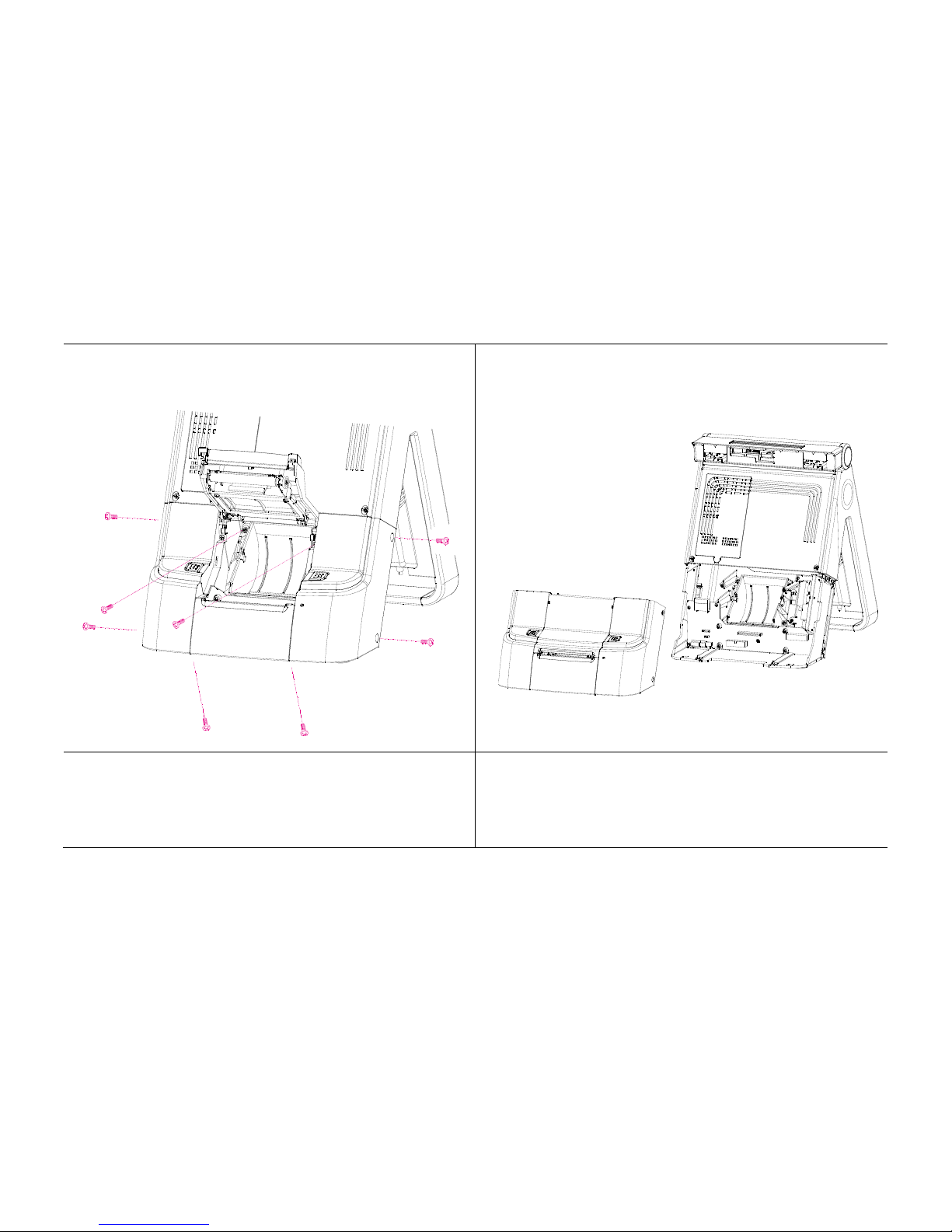
[Power Supply Unit (PSU) Replacement]
1. Raise the main display unit and remove
the HDD cover beneath.
2. Remove the 2 screws on the panel (as
shown above).
Front cover is now removed

-77-
4. Remove the 3 screws from the unit as
shown in the picture.
5. Pull out the power supply unit from the
bottom and remove.
Power supply unit is now removed
6. Replace PSU and reassemble unit using
the reverse procedure of steps 1-5 above.

-78-
[MSR Replacement]
1. Remove 2 screws from side of main unit
(as shown above).
2. Detach cable from MSR unit.
MSR is now removed
3. Replace MSR and reassemble unit using
the reverse procedure of steps 1-2 above.

-79-
[CPU Replacement]
1. Turn CPU fixing arm 180 clockwise as shown above.
2. Remove the CPU from the motherboard.
3. Insert new CPU gently into correct position.
4. Secure new CPU into place by returning the CPU fixing to its
original state.
» NB: CPU can easily be damaged if inserted incorrectly or with force.
[Pull out]
[Insert]

-80-
[Memory (RAM) Replacement]
1. Push fixtures on both sides outwards (as shown above).
2. Remove the memory from its slot.
3. Insert new memory into slot and press lightly to
fix into place.

-81-
[Display Unit Replacement]
Remove motherboard before replacing monitor. (Please refer to p.69)
1. Raise the main display unit as far up as possible.
2. Remove the 3 screws from underneath (as shown above)

-82-
3. Remove hinge cover.
4. Remove the 8 screws from beneath the cover (as shown above).

-83-
5. Disconnect cable connecting monitor to main unit.
6. Replace monitor and reassemble unit using the reverse procedure
of steps 1-5 above.

-84-
[Installing New Paper Roll]
1. Raise the main display unit.
2. Press the „OPEN‟ button to open the printer unit cover.
OPEN BUTTON

-85-
3. Insert new paper roll exactly as shown above (with loose paper
towards the bottom of the unit).
4. Draw out the end of the paper roll and close the cover.
(When closing the printer cover, press down in the middle to
ensure that the paper makes contact with the roller.)

-86-
[Paper Jam Correction]
1. Cancel printing.
2. Raise the main display unit.
3. Open the integrated printer cover and remove paper.
4. If cover doesn‟t open, check power.

-87-
1. Remove cover from underneath the printer unit.
2. You will see a small area of paper with a 2cm diameter.
3. Push down and rotate the roller until the cutter is in line with the
back of the unit.
4. Remove the jammed paper and switch power back on.
Is cover doesn‟t open by pressing the „OPEN‟ button…

-88-
[Printer Roller & Bracket Replacement]
1. Raise the main display unit.
2. Open printer cover.

-89-
3. Remove the 6 screws (as shown above) from the underside of
the printer cover.
Roller and bracket are now removed
4. Replace roller and bracket and reassemble unit using the reverse
procedure of steps 1-3 above.

-90-
[Printer Mechanism & Circuit Board Replacement]
1. Raise the main display unit.
2. Lift up the printer cover then remove the 4 screws from either
side of the main unit.
-91-
3. Remove all 8 screws from the areas shown above.
Printer mechanism cover is now removed

-92-
4. Remove the 4 screws from the area marked above.
Printer mechanism is now removed

-93-
5. After removing the printer mechanism, remove the last 5 screws
as shown above.
Printer circuit board is now removed

-94-
6-2. Upgrade and Power Supply Specifications
Upgrade reference
CPU
Intel Celeron Mobile 1.5GHz
Memory
DDR2 SODIMM 1GB (up to 2GB)
HDD
SATA 2.5inch (max 2, Default 160GB)
Power supply specification
Power Type
ATX
Operating
0 ~ 60°C (32 ~ 140°F)
Temperature Operating Humidity
0% ~ 90% relative humidity, non-condensing
Size (L x W)
6.69" x 6.69" (170 mm x 170 mm)
Weight
0.88 lbs (0.4 Kg)

-95-
6-3. Technical Specifications (Imprex_M)
CPU
Intel Celeron Mobile 1.5GHz
Chipset
Intel 91xGME
HDD
SATA 2.5inch (max 2, Default 160GB)
Memory
DDR2 SODIMM x 1 slot (Default 1GB up to 2GB)
VGA
Intel 82915GM GMCH (Independent dual display)
Display
15" TFT LCD with 5-wired resistive Touch Screen 1024 x 768 resolution
Internal I/O
Parallel
1 Port (reserved for internal printer)
USB
3 Ports (reserved for Touch controller & SCR EMV card, MSR Controller )
PS/2
1 Keyboard reserved for Pin Header
RS-232
COM 4 reserved for VFD or 2nd display
COM 5(reserved for internal printer) & COM6 reserved for 9pin header(ABR)
Extension
MINI PCI
LVDS
Main display use
External I/O
USB
Rear 2, Side 3
PS/2
Mouse 1 / Keyboard 1
RS-232
COM 1 ~ 3 with +5/12V power output on 9pin
LAN
GbE LAN
Audio
1, Line-out/ Line-in/ Mic.
C.D
Cash drawer port
Optional
MSR
Comply with ISO 7811, Support 1& 2 & 3 track
SCR
EMV level

-96-
Dallas
Dallas I-button reader
VFD
VFD type customer display (20 x 2)
2nd LCD
12” LCD : 1024 x 768 resolution
2nd HDD
2nd HDD storage
DVR
DVR Card : 4 channels support
WiFi
Mini PCI for wireless LAN
VGA
Mini PCI for VGA card
Safety & EMI
CE, FCC, KCC
Power Supply
AC 110 ~ 220V (Max.230 watt) Free voltage
OS Support
Windows 2000/XP/XPE, WEPOS, POS Ready, Linux
Dimension
360(W) × 351(H) × 344(D)
* Specifications are subject to change without prior notice
 Loading...