

Axon Instruments Axoclamp 2A Service Manual
DR. HARVEY
UNIVERSITY
DEPARTMENT
9500 GILMAN DRJVE
LA JOLLA,
J.
KARTEN,
OF
CALIFORNIA,
OF
NEUROSCIENCES, 0608
CA
92093-0608
MICROELECTRODE CLAMP
M.D.
SAN
DIEGO
AXOCLAMP-2A
SERVICE
February 1990
PLEASE CHECK FOR CHANGE INFORMATION AT THE REAR OF THIS MANUAL.
Copyright 1987, 1990 Axon Instruments, Inc.
No part of this manual may be reproduced, stored in a retrieval system, or transmitted, in any
form or by any means, electronic, mechanical, photocopying, microfilming, recording, or
otherwise, without written permission from Axon Instruments, Inc.
QUESTIONS? Call (415) 571-9400
part Number 2500001 REV A
bx U.S.A.
Ul
COPYRIGHT
THE CIRCUITS AND INFORMATION IN THIS MANUAL ARE COPYRIGHTED AND
MUST NOT BE REPRODUCED IN ANY FORM WHATSOEVER WITHOUT WRITTEN
PERMISSION FROM AXON INSTRUMENTS, INC.
WARNING
THIS INSTRUMENT OPERATES FROM LINE VOLTAGES. DO NOT PERFORM ANY
SERVICING UNLESS YOU ARE QUALIFIED TO DO SO. LINE VOLTAGES ARE
PRESENT IN THE LEFT-MOST SECTION BETWEEN THE POWER ON/OFF SWITCH AND
THE LINE INPUT FILTER.
DR. HARVEY
UNIVERSITY
DEPARTMENT
9500 GILMAN DRIVE
LA JOLLA,
J.
KARTEN,
OF
CALIFORNIA,
OF
NEUROSCIENCES, 0608
CA
92093-0608
M.D.
SAN
DIEGO
AXOCLAMP SERVICE, COPYRIGHT FEBRUARY 1990, AXON INSTRUMENTS, INC.
IV
CThis page is intentionally left blank)
AXOCLAMP SERVICE, COPYRIGHT FEBRUARY 1990, AXON INSTRUMENTS, INC.
TABLE OF CONTENTS
Page
THEORY OF OPERATION 1
GENERAL 1
POWER SUPPLY 1
REMOTE INPUT AND CONTROL LOGIC 2
5V REFERENCE / STEP COMMAND GENERATOR / DESTINATION SWITCH 3
MICROELECTRODE 1 (MEl) 3
MICROELECTRODE 2 (ME2) 3
VOLTAGE CLAMP AND VI CONTINUOUS 4
MAINTENANCE 7
SPECIFICATIONS 9
DRAWING CONVENTIONS. A-1
CIRCUITS ....A-2
ADJUSTMENT PROCEDURE B-1
REPLACABLE PARTS C-1
AXOCLAMP SERVICE, COPYRIGHT FEBRUARY 1990, AXON INSTRUMENTS, INC.
VI
CThis page is intentionally left blank)
AXOCLAMP SERVICE, COPYRIGHT FEBRUARY 1990, AXON INSTRUMENTS, INC.
Vll
LIST OF ILLUSTRATIONS
Page
Fig. 1. Timing Diagram ; 5
Fig. 2. Differential Measurements on Oscilloscope B-7
CIRCUITS
Remote Buzz Control A-2
5V Reference / Destination Switch A-3
Current Command & Headstage Drive Circuit (MEl) A-4
Ipi Monitor Circuit A-5
Current Command & Headstage Drive Circuit (ME2) A-6
ME2 12/V2 A-7
Bridge / Monitor / VI Continuous.. A-8
Voltage Clamp & VI Continuous A-9
I Display Select / V Bath / Vimial Ground A-10
Remote Input & Control Logic...... A-U
Clock and Control Logic A-12
Headstage and Model Cell Configuration A-13
Power Supply Axoclamp A-14
Thumbwheel to Voltage Converter A-15
AXOCLAMP SERVICE, COPYRIGHT FEBRUARY 1990, AXON INSTRUMENTS, INC.
Vlll
CThis page is intentionally left blank)
AXOCLAMP SERVICE, COPYRIGHT FEBRUARY 1990, AXON INSTRUMENTS, INC.
THEORY OF OPERATION Page 1
THEORY OF OPERATION
GENERAL
The AXOCLAMP-2A contains amplifiers for 2 separate microelectrodes (MEl and ME2).
In Bridge mode both microelectrodes are used for continuous current passing and voltage recording.
In DCC mode (discontinuous current clamp) the current in MEl is chopped by high-speed switching
circuitry and the voltage on MEl is sampled between current pulses. ME2 is used for continuous current
passing.
There are three voltage-clamp modesDuring voltage clamp current is passed down the microelectrode to
maintain the cell membrane at the command voltage. The required current is determined by a negative
feedback circuit.
1.
TEVC mode (two-electrode voltage clamp) is used for conventional voltage clamping. MEl is
used to record membrane potential (Vm)- ME2 is used to pass the required current.
2.
dSEVC mode (discontinuous single-electrode voltage clamp) uses MEl for both voltage recording
and current passing. The required input of the negative feedback circuit is Vm. Because of the
large resistance of normal intracellular electrodes Vn, cannot be measured during current passing.
Therefore the current in MEl is chopped by high-speed switching circuitry and the voltage on MEl
is sampled between current pulses. ME2 can be independently used as in Bridge mode.
3.
cSEVC mode (continuous single-electrode voltage clamp). Like dSEVC, this mode uses MEl for
both voltage recording and current passing during voltage clamp. Unlike dSEVC, in this mode
current passing is continuous and thus the voltage drop in the electrode due to current flow is
measured. This voltage drop introduces an error. cSEVC only works with very low resistance
suction electrodes so that the error is small. The MEl Bridge potentiometer allows some of this
voltage drop to be compensated.
Command voltages for both current passing and voltage clamping are generated internally but timing for
these commands must come from external sources.
For a complete description of the operation of the AXOCLAMP-2A see the Theory and Operation manual.
POWER SUPPLY - ASSEMBLY No. AlOOl
Located in the left-hand section of the instrument.
WARNING: Line voltages are present in the power-supply section.
The line input connector contains an RFI filter, the fuse in use and a spare fiise. A slide switch on the
circuit board puts the two primary windings into series or parallel connection for 230 V or 115 V
operation respectively. Line voltages from 200-260 V and 100-130 Vac are acceptable.
AXOCLAMP SERVICE, COPYRIGHT FEBRUARY 1990, AXON INSTRUMENTS, n<C.
Page 2 THEORY OF OPERATION
Five regulated outputs are generated: -1-30 V, -30 V, -1-15 V, -15 V, -1-5 V. Standard 3-terminal
regulators are used. Test points on the circuit board allow the regulator input and ou^ut voltages to be
conveniently measured. 2 mV of line-fi-equency noise and 2 mV of wideband noise are acceptable. Tliis
noise is rejected by the rest of the circuitry.
REMOTE INPUT AND CONTROL LOGIC - ASSEMBLY No. A1002
Power Distribution
All power for the main circuit board comes from the power supply board to connector J8.
Mode Select
All switching between modes is done on the main circuit board by relays. U6, U7 and U8 are used to
decode the Mode Select switches. U9 contains 7 Darlington transistors for driving relays and the Mode
lamps.
Clock Sequence Generator
Ul-US are used to generate the logic signals for controlling the high-speed switching between current
passing and voltage recording. Ul is a voltage controlled oscillator (VCO) whose frequency is set by the
Rate control. U2 is a Johnson counter which divides die VCO clock by ten and has an output cycle
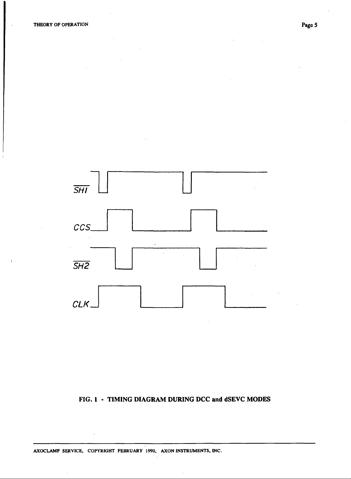
divided into ten segments. U3 and U4 convert the ten segments into the required control signals (see
Fig. 1), SHI activates the main sample-and-hold (SHI) in the MEl section. SH2 activates the sampleand-hold used for current measurement. CCS switches the MEl constant current source from current
passing to voltage recording. In each cycle, a sample of voltage is taken (10% of cycle) and then current
passing begins (30% of cycle). Shortly after current passing begins the sample-and-hold used for current
measurement.is activated (20% of cycle). A HI logic signal on the Blank Activate input prevents SHI
ftrom taking samples but does not otherwise affect the cycling.
U13 is a quad 2-input multiplexer used for synchronizing the clocks of two AXOCLAMPs. Unless a
second AXOCLAMP is connected all the switches in U13 remain in the positions shown.
U15 is a frequency-to-voltage converter. It is used to drive the voltmeter which indicates the Sample rate.
Remote Clear Buzz
Relays used for Buzz and Clear are driven by Darlington transistors in UIO. Each transistor can be
switched on by a front-panel switch, or by a logic HI signal applied through the remote connector or rear-
panel Buzz jacks.
AXOCLAMP SERVICE, COPYRIGHT FEBRUARY 1990, AXON INSTRUMENTS, INC.
THEORY OF OPERATION Page 3
5V REFERENCE / STEP COMMAND GENERATOR / DESTINATION SWITCH - ASSEMBLY
No.
A1002
Voltage reference A2 and inverting amplifier A3 provide a stable -H5V
(+VR)
and -5V
(-VR)
reference for
use by the rest of the circuit.
Al and A2 located on the thumbwheel switch board comprise a multiplying D/A converter. The output of
A2 corresponds to the setting of the switch. Polarity is changed by swapping the D/A input between
and
-VR.
U12 is a CMOS switch used to convert the D/A output into a ground-referenced voltage step.
-i-VR
Duration of the step is set by the External Step Activate input or the front-panel switch, llie Destination
switch determines whether tiie step voltage will be passed to the MEl section, the ME2 section, or the
voltage clamp section. A calibration signal is generated in Al and is proportional to the setting of the
thumbwheel switch. Duration of the calibration pulse is set by the extemal Cal. Activate input.
MICROELECTRODE 1 (MEl) - ASSEMBLY No. A1002
Transistors Q3 and Q4, and current regulator diodes CRD3 and CRD4 comprise a floating ± 10 V power
supply for the headstages. The transistors are configured to simulate 10 V zeners. The common point of
the floating supply is driven by the electrode voltage (VIA). A12 is a ±30 V amplifier providing positive
feedback to the headstage input through
CN
(inside the headstage). This feedback compensates the input
capacitance (capacitance neutralization).
AIS and Ro (inside the headstage) comprise a constant current source (CCS). The command voltage on
R53 is forced across Ro thereby setting die electrode current. The command voltage either comes from the
voltage-clamp circuit or from summing amplifier A16, depending on the position of relay RL6. The gain
of A16 is boosted 3.3 times by RL6 during DCC mode. This 3.3 boost compensates for the 30% current
duty cycle during discontinuous current passing. Relays RL8-9 set the command voltage of the CCS to
large positive or negative values. The resulting large currents are used to clear blocked electrodes.
The Bridge pot, A28 and A32 are used to subtract the voltage drop across the electrode from the total
electrode voltage. This voltage drop is the product of the measured current (IIA) and the Bridge pot
setting. In DCC mode the Bridge pot is disabled by RLIO. In cSEVC mode the subtraction range is
reduced to one tenth. A19 buffers a first-order lowpass filter.
Electrode current is proportional to the voltage drop across Ro. This is measured by A14. Sample-and-
hold A17 acts as a unity-gain buffer during Bridge mode. During DCC it samples the current pulses.
RLll changes the current scaling during DCC to compensate the measurement for the 30% duty cycle.
A18 buffers a first-order lowpass filter.
MICROELECTRODE 2 (ME2) - ASSEMBLY No. A1002
This section is similar to the ME2 section with the following differences.
The CCS (A6) is connected to the command summing amplifier (A9) in all modes. A9 has a fixed gain.
During two-electrode clamp relay RL2 bypasses the CCS and connects the output of the ±30 V amplifier
A7 to Ro. There is no lowpass output filter.
AXOCLAMP SERVICE, COPYRIGHT FEBRUARY 1990, AXON INSTRUMENTS, INC.
Page
4
THEORY
OF
OPERATION
Switches
switches
VOLTAGE CLAMP
S3-S
determine
is
activated depending
AND VI
the
position
on the
CONTINUOUS - ASSEMBLY No. AlOOl
Voltage Clamp
Tlie microelectrode headstage voltage
lowpass filtered
VB =
O
V.
The output
modes)
A22
and
(20VM) is
summing amplifier
by A29 and
of
A21 goes through
becomes
used
in the MEl
the
input
A24. In
subtracted from
the
of
A22, a high-speed unity-gain sample-and-hold amplifier.
section
A24,
20VM is
outof A27.
The phase-shift network adds phase
and
A26 to
corrects
produce
the
total gain during cSEVC.
the
voltage-clamp output
lag or
of the
decimal point
in the
current meter.
position ofthe Current Display Select switch
is
amplified
lowpass Anti-Aliasing filter (which
to
form
lead
20
times
in
amplifier A21.
VIA in A21. If no
die IOVM
compared with
to the
fed to MEl
output.
the
output
of
during SEVC
voltage-clamp command voltages coming
A24.
The
bath headstage
is
useful
20VM
The
also becomes
signal
and ME2
One of
(S2).
bath potential
is
used,
in DCC and
The
the
is
then amplified
during TEVC.
these three
(VB)
is
R218
sets
dSEVC
output
of
input
of the
in A25
RL12
Amplifier A23a buffers
the
input
Monitor output. A23b subtracts
Amplifler A20c detects
when
the
Holding Position potentiometer balances
the
condition
Vl Continuous
The offeet voltage generated
potential
is
subtracted
in
AlOb
in
and the
to A22 so
the
sampled potential
of
zero output from
A20a
is
added
calibration signal
that this signal
so
that
the
VIA.
to the
buffered headstage voltage
is
added.
can be
observed
the
Monitor signed remains centered
by the
experimenter
on the
on OV.
voltage-clamp circuit. This condition occurs
(VIB) in A18a.
Badi
AXOCLAMP
SERVICE, COPYRIGHT FEBRUARY
1990,
AXON INSTRUMENTS,
INC.
THEORY OF OPERATION
SHI
Pages
ccs_
SH2
CLK_\
FIG. 1 - TIMING DIAGRAM DURING DCC and dSEVC MODES
AXOCLAMP SERVICE, COPYRIGHT FEBRUARY 1990, AXON INSTRUMENTS, INC.
Page 6
THEORY OF OPERATION
CThis page is intentionally left blank)
AXOCLAMP SERVICE, COPYRIGHT FEBRUARY 1990, AXON INSTRUMENTS, INC.
MAINTENANCE
Page 7
MAINTENANCE
Adjustment and repair should only be attempted by skilled electronic technicians or engineers.
CAUTION
Line voltage is connected to some of the transformer leads and some parts of the power-supply board in the
left hand side of the instrument. Always unplug the power cord before attempting to handle or repair
these sections.
ACCESS
All test points and trim potentiometers can be accessed by removing the top cover.
All components can be desoldered from the main circuit board without removing the board. Simply
remove the bottom cover for access to the non-component side of the board.
ROUTINE MAINTENANCE
Routine maintenance is not required. The adjustment procedure should be performed after repairs to the
main circuit board but not odierwise.
As required, the operator of the instrument can perform the headstage leakage current adjustment
described in the operator's manual.
AXOCLAMP SERVICE, COPYRIGHT FEBRUARY 1990, AXON INSTRUMENTS, INC.
Page 8
MAINTENANCE
CThis page is intentionally left blank)
AXOCLAMP SERVICE, COPYRIGHT FEBRUARY 1990, AXON INSTRUMENTS, INC.
SPECIFICATIONS
MODES
Page 9
SPECIFICATIONS
Five main operating modes selectable by color-coded illuminated push buttons,
These are:
1.
Bridge
2.
3.
4.
5.
DCC:
dSEVC
cSEVC:
TEVC:
Discontinuous Current Clamp
Discontinuous Single-Electrode Voltage Clamp
Continuous Single-Electrode Voltage Clamp
Two-Electrode Voltage Clamp
MICROELECTRODE AMPLIHERS (Two Channels)
Unity-Gain Headstages:
Standard is tiie HS-2L type. HS-2M types are the same except:
1) die noise is greater by about 20%
2) the capacitance neutralization range is extended.
HS-2MG types are similar to the HS-2M types except diat the case is
grounded instead of driven.
Hum Oine-frequency pickup):
Headstage Current Gain (H):
Less than 10 /iV peak-to-peak, grounded input.
Available in 5 values (specify two-with order). Select on basis of
cell input resistance (Ru,) and maximum current capacity (Imax).
H = xO.OOOl for ion-sensitive electrodes
H = xO.Ol for Rin greater dian about 300 MQ
H = xO.l for Rin about 30-300 MO
H = X 1 (standard) for Rin about 3-30 Mfl
H = xlO for Rin about 300 kO to 3 MO
These ranges are suggested for optimum performance. Some
overlap is allowable.
or remotely.
Maximum Current:
Noise with grounded input:
Imax = 1000 X H nA.
5 /iV rms measured wiUi a 10 kHz single-pole filter in the
measurement circuit.
Noise with a source resistance:
51 (47) fiW rms measured with a 10(100) MQ source resistance and
capacitance neutralization adjusted for a 10(1) kHz bandwidth and
with a 10 (1) kHz single-pole- filter in the measurement circuit.
Values are for H = xl (xO.l), HS-2L headstage.
1%
Settling Time:
16(54) /iS for a voltage step applied to the input via a 10(100) MQ
low-capacitance resistor and 16(60) /iS for a current step into the
same resistor. Capacitance neutralization adjusted for zero
overshoot. Values are for H = xl (xO.l).
AXOCLAMP SERVICE, COPYRIGHT FEBRUARY 1990, AXON INSTRUMENTS, INC.

Page 10
±
13
Working Input Voltage Range:
*Note: For the xO.OOOl headstage, die input resistance of each headstage is measured individually. The
unique test results are supplied with each xO.OOOl headstage.
V for transients and steady state, protected to ±30 V.
Input Resistance: lO'-^-lO'* Q, H = x
10"
0, H = X .01
1012 Q, H = xO.l
10"
0, H = X 1
10>o 0, H = X 10
0.0001
SPECIFICATIONS
(see note)'
Input Capacitance:
Input Leakage Current:
Input Leakage Current vs. Temperature:
Omset Neutralization Range:
Capacitance Neutralization Range:
Buzz:
Buzz Duration:
Not relevant. See 1% settling time and noise specifications.
Adjustable to zero.
±500 mV. Ten-tum potentiometers.
HS-2L: -1 to 7 pF
HS-2M: -2to20pF
HS-2MG:-4tO 18 pF
These values apply when headstage is used with microelecfrode
1 amplifier. With microelecfrode 2 amplifier the maximum values
are doubled.
Instantly increases capacitance neufralization to cause oscillation.
Operated by spring-loaded pushbutton switch, footswitch or by
Remote Buzz Duration control. The latter allows the Buzz
duration to be set in the range 1-50 ms.
1-50 ms when activated by the remote buzz control.
10
100
1
10
fA/
fA/
pA/
pA/
H = xO.OOOl
"C,
H = xO.Ol, xO.l
°c.
H = xl
"C,
H = xlO
°c.
Clwir:
Bridge Balance Range:
Digital Voltmeters:
AXOCLAMP SERVICE, COPYRIGHT FEBRUARY 1990, AXON INSTRUMENTS, INC.
Forces ±Imax through the microelecfrode. Spring-loaded toggle
switch.
10-^H MB/turn in Bridge mode. l-^H MO/turn in cSEVC mode.
Ten-turn potentiometers.
Voltage Displays:
Current Displays:
Scaling is set by miniature panel switches
II,
h and Lirt.
Currents exceeding the digital display range can be measured on
the BNC outputs.
± 1999mV.
± 19.99 pA,
± 1.999 nA,
± 19.99 nA,
± 199.9 nA,
± 1.999 mA,
Separate meters for Vi and V2
H = x
0.0001
H = x .01
H = x.0.1
H = X 1
H = X 10
Display selections are
SPECIFICATIONS
Page II
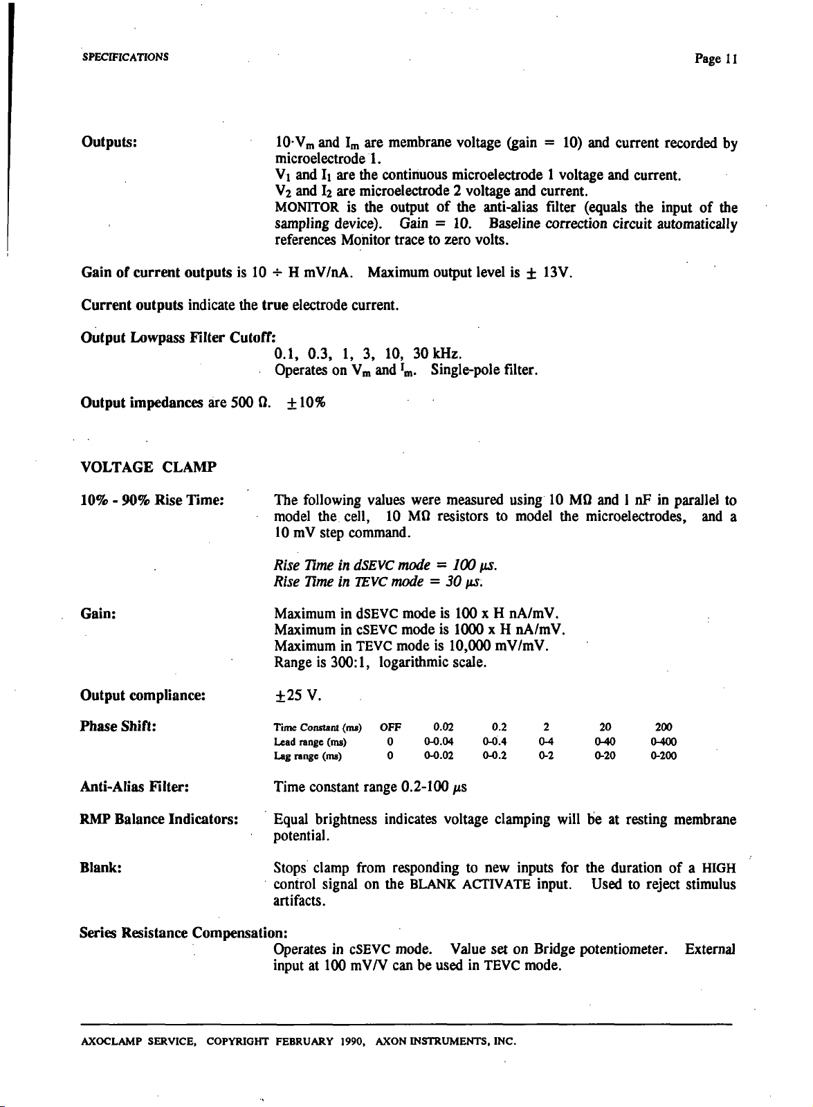
Outputs:
10-Vm and Im are membrane voltage (gain = 10) and current recorded by
microelecfrode 1.
Vl and II are the continuous microelecfrode 1 voltage and current.
V2 and I2 are microelecfrode 2 voltage and current.
MONITOR is the output of the anti-alias filter (equals the input of the
sampling device). Gain = 10. Baseline correction circuit automatically
references Monitor frace to zero volts.
Gain of current outputs is 10 -^ H mV/nA. Maximum output level is ± 13V.
Current outputs indicate the true elecfrode current.
Output Lowpass Filter
Cutoff:
0.1,
0.3, 1, 3, 10, 30 kHz.
Operates on Vm and 'm- Single-pole filter.
Output impedances are 500 0. ± 10%
VOLTAGE CLAMP
10%
- 90% Rise Time:
The following values were measured using 10 MQ and 1 nF in parallel to
model the cell, 10 MQ resistors to model the microelecfrodes, and a
10 mV step command.
Rise Time in dSEVC mode = 100 us.
Rise Time in
Gain:
Maximum in dSEVC mode is 100 x H nA/mV.
Maximum in cSEVC mode is 1000 x H nA/mV.
Maximum in TEVC mode is 10,000 mV/mV.
Range is
Output compliance:
Phase Shift:
Anti-Alias Filter:
RMP Balance Indicators:
±25 V.
Time Constant (ms)
Lead range (ms)
Lag range (ms)
Time constant range 0.2-100 /ts
Equal brightness indicates voltage clamping will be at resting membrane
potential.
Blank:
Stops clamp from responding to new inputs for the duration of a HIGH
control signal on the BLANK ACTIVATE input. Used to reject stimulus
artifacts.
Series Resistance Compensation:
Operates in cSEVC mode. Value set on Bridge potentiometer. Extemal
input at 100 mV/V can be used in TEVC mode.
TEVC
300:1,
mode = 30 us.
logarithmic scale.
OFF
0
0
0.02
0.0.04
0.0.02
0.2
0^.4
0^.2
2
OA
0-2
20
(MO
0-20
200
0-400
0-200
AXOCLAMP SERVICE, COPYRIGHT FEBRUARY 1990, AXON INSTRUMENTS, INC.
Page 12
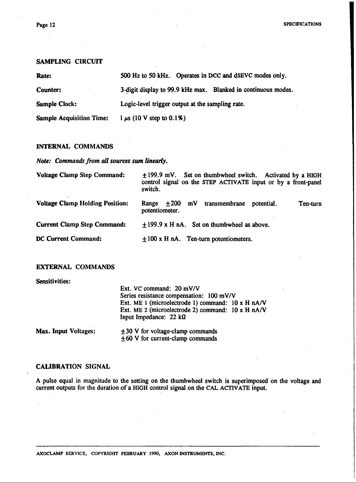
SAMPLING CIRCUIT
SPECIFICATIONS
Rate:
Counter:
Sample Clock:
Sample Acquisition Time:
500 Hz to 50 kHz. Operates in DCC and dSEVC modes only.
3-digit
display to 99.9 kHz max. Blanked in continuous modes.
Logic-level frigger output at the sampling rate.
l/ts(10Vst^to0.1%)
INTERNAL COMMANDS
Note: Commands from all sources sum linearly.
Voltage Clamp Step Command:
± 199.9 mV. Set on thumbwheel switch. Activated by a HIGH
control signal on the STEP ACTIVATE input or by a front-panel
switch.
Voltage Clamp Holding Position:
Range ±200 mV fransmembrane potential,
potentiometer.
Current Clamp Step Command:
DC Current Command:
± 199.9 X H nA. Set on thumbwheel as above.
± 100 X H nA. Ten-tum potentiometers.
Ten-tum
EXTERNAL COMMANDS
Sensitivities:
Ext. VC command: 20 mV/V
Series resistance compensation: 100 mV/V
Ext. ME 1 (microelecfrode 1) command: 10 x H nA/V
Ext. ME 2 (microelecfrode 2) command: 10 x H nA/V
Input Impedance: 22 kQ
Max. Input Voltages:
±30 V for voltage-clamp commands
±60 V for current-clamp commands
CALIBRATION SIGNAL
A pulse equal in magnitude to the setting on the thumbwheel switch is superimposed on the voltage and
current outputs for the duration of a HIGH control signal on the CAL ACTIVATE input.
AXOCLAMP SERVICE, COPYRIGHT FEBRUARY 1990, AXON INSTRUMENTS, INC.
SPEcniCATiONS Page 13
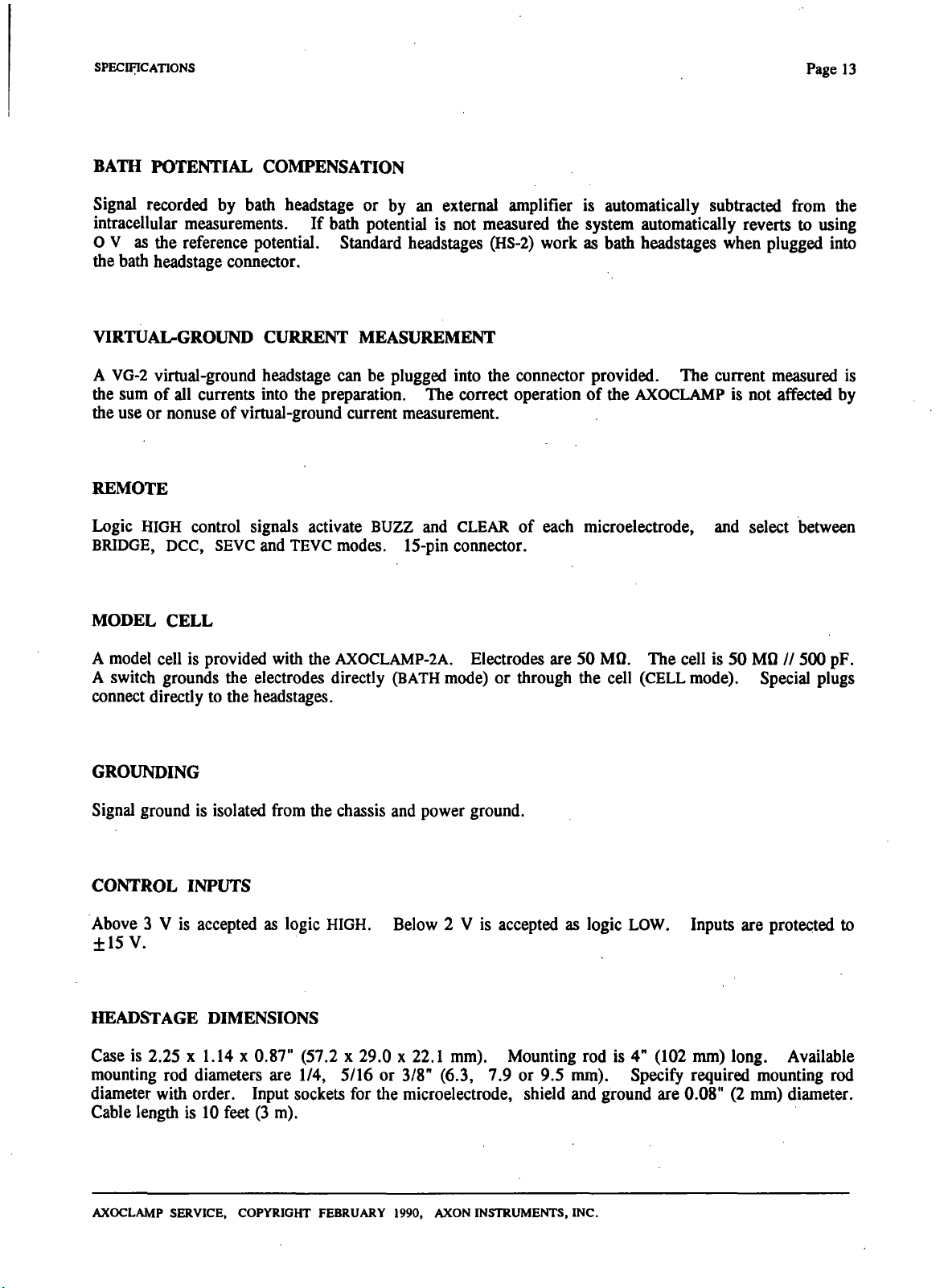
BATH POTENTIAL COMPENSATION
Signal recorded by bath headstage or by an extemal amplifier is automatically subfracted from the
infracellular measurements. If badi potential is not measured the system automatically reverts to using
O V as the reference potential. Standard headstages CHS-2) work as bath headstages when plugged into
the bath headstage connector.
VIRTUAI^GROUND CURRENT MEASUREMENT
A VG-2 virtual-ground headstage can be plugged into the connector provided. The current measured is
the sum of all currents into the preparation. The correct operation of the AXOCLAMP is not affected by
the use or nonuse of virtual-ground current measurement.
REMOTE
Logic HIGH control signals activate BUZZ and CLEAR of each microelecfrode, and select between
BRIDGE, DCC, SEVC and TEVC modes. 15-pin connector.
MODEL CELL
A model cell is provided widi die AX0CLAMP-2A. Electrodes are 50 MQ. The cell is 50 MQ // 500 pF.
A switch grounds the electrodes directly (BATH mode) or through the cell (CELL mode). Special plugs
connect directly to the headstages.
GROUNDING
Signal ground is isolated from the chassis and power ground.
CONTROL INPUTS
Above 3 V is accepted as logic HIGH. Below 2 V is accepted as logic LOW. Inputs are protected to
±15 V.
HEADSTAGE DIMENSIONS
Case is 2.25 x 1.14 x 0.87" (57.2 x 29.0 x 22.1 mm). Mounting rod is 4" (102 mm) long. Available
mounting rod diameters are 1/4, 5/16 or 3/8" (6.3, 7.9 or 9.5 mm). Specify required mounting rod
diameter with order. Input sockets for the microelectrode, shield and ground are 0.08" (2 mm) diameter.
Cable lengdi is 10 feet (3 m).
AXOCLAMP SERVICE, COPYRIGHT FEBRUARY 1990, AXON INSTRUMENTS, INC.
 Loading...