


AXMINSTER
Hobby
SERIES
MB1931(TP2000)
Benchtop Thicknesser
Code 104279
Original Instructions
AT&M: 23/04/2018
BOOK REF : 104860

Index of Contents
Declaration of Conformity 02
What’s Included 03-04
General Instructions for 230V Machines 04
Specific Instructions for Thicknessing Machines 05
Specification 05
Assembly 06-07
Illustration & Parts Description 08-09-10-11
Setup & Adjustment 12-13
Operating Instructions 14
Changing the Blades 15-16-17
Maintenance 18-19
Troubeshooting 20
Exploded Diagrams/Lists 21-22-23
Wiring Diagram 23
CE Certificate 24-25
Notes 26-27
EU Declaration of Conformity
Cert No: MB1931(TP2000)
Axminster Tools & Machinery Ltd
Axminster Devon
EX13 5PH UK
axminster.co.uk
declares that the machinery described:-
Type Thicknesser
Model MB1931
Signed
Andrew Parkhouse
Operations Director
Da te: 06/06/2016
EU Declaration of Conformity
This machine complies with the following directives:
2006/42/EC
EN 55014-1: 2006/A2:2011
EN 55014-2: 1997/A2: 2008
EN 61000-3-2: 2014
and conforms to the machinery example for which the
EC Type-Examination Certificate No S50328303 001, BM50328304 001, E8A 16 06 41469 839
has been issued by TÜV Rheinland (China) Ltd. (Member of TÜV Rheinland Group)
at: Unit 707, AVIC Bldg., No. 10B, Central Road, East 3rd Ring Road,
Chaoyang District, Beijing, 100022, P.R. China
and complies with the relevant essential health and safety requirements.
EN 61000-3-11: 2000
EN 61029-1: 2009+A11
61029-2-3: 2011
AfPS GS 2014: 01
The symbols below advise the correct safety procedures when using this machine.
Fully read manual
and safety instructions
before use
Ear protection
should be worn
Eye protection
should be worn
2
Dust mask
should be worn
HAZARD

What’s Included
Quantity Item Part Model Number
1 Benchtop Thicknesser A MB1931( TP2000)
4 Rubber Feet B
1 Rise & Fall Operating Handle
with M6 Hex Screw and Spring Washer C
1 Blade Setting Gauge D
1 8-10mm Spanner E
1 4-5mm Hex Key F
4 M8 x 45mm Nex Bolts to secure thicknesser to workbench G
A
B
C
3

What’s Included
G
D
F
General Instructions for 230V Machines
The following will enable you to observe good working
practices, keep yourself and fellow workers safe and maintain
your tools and equipment in good working order.
WARNING!! KEEP TOOLS AND EQUIPMENT
OUT OF REACH OF YOUNG CHILDREN
KEEP WORK AREA AS UNCLUTTERED AS IS PRACTICAL.
UNDER NO CIRCUMSTANCES SHOULD CHILDREN BE
ALLOWED IN WORK AREAS.
Mains Powered Tools
• Tools are supplied with an attached 13 Amp plug.
• Inspect the cable and plug to ensure that neither are
damaged. Repair if necessary by a suitably qualified person.
• Do not use when or where it is liable to get wet.
Workplace
• Do not use 230V a.c. powered tools anywhere
within a site area that is flooded.
• Keep machine clean.
• Leave machine unplugged until work is about to commence.
• Always disconnect by pulling on the plug body
and not the cable.
• Carry out a final check e.g. check the cutting tool
• Ensure you are comfortable before you start work,
• Wear appropriate safety clothing, goggles, gloves,
• If you have long hair wear a hair net or helmet to prevent it
• Consideration should be given to the removal of rings and
• Consideration should also be given to non-slip footwear etc.
• If another person is to use the machine, ensure they are
• Do not use the machine if you are tired or distracted.
• Do not use this machine within the designated safety areas
• Check cutters are correct type and size, are undamaged
• OBSERVE…. make sure you know what is happening
E
is securely tightened in the machine and the correct
speed and function set.
balanced, not reaching etc.
masks etc. Wear ear defenders at all times.
being caught up in the rotating parts of the machine.
wristwatches.
suitably qualified to use it.
of flammable liquid stores or in areas where there may be
volatile gases.
and are kept clean and sharp, this will maintain their
operating performance and lessen the loading on the
machine.
around you and USE YOUR COMMON SENSE.
4

Specific Instructions for Thicknessing Machines
When machining, long pieces of timber tend to be unstable.
Bolting the machine to a bench increases stability. It is also
advisable to use two outfeed roller stands. However you have
mounted your machine ensure it is secure before you
commence work.
Note: Check there are no foreign objects e.g. old nails,
screws, small stones etc embedded in the material you
are about to machine.
WARNING!! DO NOT CARRY OUT ANY
CLEANING OR MAINTENANCE WITH THE
MACHINE CONNECTED TO THE MAINS SUPPLY!
THIS THICKNESSER IS FOR
MACHINING TIMBER ONLY!
1. Check knives are clean and sharp.
2. Check thicknessing table is clear of debris before
commencing work.
3. Check there is no excess build up of resin etc.,
on the thicknessing bed.
4. Check feed rollers are clean and unclogged.
5. Check the guards are in place and secure
before using the machine.
6. Do not stand directly in line with the infeed or the
outfeed of the machine especially when starting up.
7. Do not force the timber through the machine, it has
its own feed rollers and will feed itself at the correct rate.
8. The machine is designed for PLANING TIMBER ONLY.
9. Do not put man-made materials through this machine.
10. Remove loose knots from timber before planing.
11. Always allow machine to run up to full speed before
introducing the timber.
12. If your machine is fitted with ‘pass over rollers’
make sure that they are rotating freely.
Specification
Code 104279
Model MB1931(TP2000)
Power 1.8 kW
Feed Speed 7 m/min
Cutterblock Speed 9,000rpm
Cutterblock Diameter 48mm
Max Thicknesser Capacity 153mm
Max Planing Width 318mm
Max Depth of Cut Thicknesser 2.5mm
Noise Level dB (A) (Sound Pressure Level) LpA: 99.6dB (A)
(Sound Power Level) LwA: 112.6dB (A)
(Uncertainty) K: 3.0dB (A)
Knives HSS (Resharpenable) x 2
Min Extraction Airflow Required 390 m³/hr
Dust Extraction Outlet 50mm
Overall L x W x H 560 x 360 x 580mm
Weight 30 kg
5

Assembly
Fitting Rubber Feet Rise & Fall Operating Handle
1
2
1
C
B
2
4
33
4
6

Workbench Assembly
Assembly
1
3
5
G
2
4
Place a washer to each corner as shown
Mark the four holes with an pencil;
drill a 9mm hole to each corner
G
6
Locate the four M8 Hex bolts (G) and insert down through
each hole. Using four M8 washers nuts, secure in place
7

Illustration & Parts Description
NVR Switch shroud
Thicknessing head
Rise & Fall handle
Motor brush
Extension table Roller Width guide
Pointer
Scale
Extension table levelling bolt
8

A
Illustration & Parts Description
C
B
NVR switch emergency stop (A),
Circuit breaker ‘RESET’ switch (B), On/Off buttons (C)
A
Cutter block (A), Anti-kickback fingers (B), Feed rollers (C)
B
Thicknessing head rise & fall control handle
C
9
Thicknessing scaleTool compartment

Illustration & Parts Description
Cutter block cover Motor & gearbox
Motor brush
Dust extraction
Threaded shaft
Thicknessing bed
318mm
10

A
Illustration & Parts Description
C
B
Cutter block (A), Blade holder (B), Blade (C), Square nut (D)
E F
Width guides (E-F)keep the timber within the boundaries of the cutter block
D
G
Cutter block cover with a 50mm duct extraction outlet (G) Folding infeed outfeed
extension tables
11

Setup & Adjustment
Levelling Extension Tables
Wind the thicknessing head up and place a straight edge across
the extension tables. Adjust the two stop bolts (A) below the
table until level is correct.
1
B
Loosen nut
5
2
3
A
Adjust stop bolt
6
7
4
8
A
B
Table stop bolt (A) and locking nut (B)
12

Setup & Adjustment
Setting Cutter Head to Thicknessing Bed
Plane a piece of timber and measure the thickness after
the cut. If the thicknesses are different on both sides of
the work piece, follow the instructions below:
Use a piece of hardwood to make a tool gauge block
(Illustrations 1-2).
1
4
5
Gauge block
2
Make the following adjustments:
6
7
Cutter head adjusting nut
3
Adjust the height nuts on either side to suit the gauge block
then tighten when level. Reassemble the thicknesser and
remove gauge block.
13
Continues over...
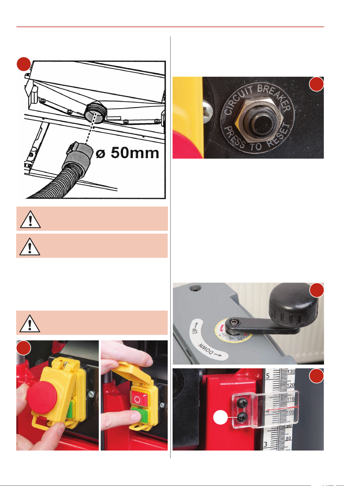
Operating Instructions
Connect the thicknesser to a dust extractor with an air volume
of 700m3/hr.
1
CONNECT THE THICKNESSER TO THE MAINS
SUPPLY!
CLEAR ALL TOOLS AWAY FROM THE WORK
AREA!
Lift up the emergency stop shroud and press the GREEN ‘ON’
button (2). Let the thicknesser reach full speed and feed a piece
of timber through from the infeed table. Wait until the timber
has passed through then switch off the machine by pressing
the RED ‘OFF’ button and wait until the machine comes to a
complete stop.
Circuit Breaker ‘RESET’ Switch
The thicknesser has an overload switch (3). If an overload
occurs, the switch will pop out. Wait several minutes before
pressing in the switch to reset the machine.
3
Depth of Cut Scale
It is important that the depth of cut scale reads accurately.
Adjust as follows.
• Turn the rise & fall handle (4) to the required depth.
NOTE: one revolution of the handle equals 1.6mm of depth.
• Switch ‘ON’ the thicknesser and wait until it reaches full speed.
• Feed a piece of timber through.
• Switch ‘OFF’ and wait until it comes to a complete stop.
• Compare the measurement on the timber with the reading on
the scale. (5) If the reading is different, adjust the scales pointer
by loosening the two screws (A).
• Feed another piece of timber through to check the depth of
cut and make further adjustments if necessary.
4
2
NEVER PLANE MORE THAN 3MM IN ONE PASS!
NEVER PLANE A BOARD UNDER 127MM IN
LENGTH!
5
A
14

Changing the Blades
1
2
DISCONNECT THE MACHINE FROM THE MAINS
SUPPLY BEFORE CONTINUING!
E
Loosen
6
7
3
4
8
Remove assembly
9
Clean cutter block
5
15
10
Continues over...

Changing the Blades
B
A
C
D
E
Cutter Block Assembly
Blade Setting Gauge A
Blade B
Blade Holder C
Spring D
Clamping Square Nut E
16

Changing the Blades
11
12
CAUTION!! THE BLADES ARE SHARP!
Blade
Slot
Pin
15
16
13
14
Tighten
D
17
E
18
17
19
Blade

Maintenance
Changing the Motor Brushes
DISCONNECT THE MACHINE FROM THE
MAINS SUPPLY BEFORE CONTINUING!
Check the carbon brushes every three months. Replace if worn.
Take careful note of the orientation of the
brushes when you remove them, remember
that they have bedded themselves to the
profile of the commutator in that position.
If you fit them reversed they may not be in
exactly the same position, which can cause
excessive sparking and heat until they have
re-bedded themselves.
1
4
5
2
3
6
7
18
8

Checking the Condition of Drive Belt Checking the Condition of Drive Chain
Maintenance
• Visually inspect the drive belt for damage or slackness every
month.
1
2
• Once a month, check the chain drive has not become too
slack or the teeth on the sprockets too worn. Check the chain
has not become clogged.
1
3
4
2
3
• Clean the chains, remove build-up of dust or wood shavings
and apply a light coat of greese over the chains.
• Remove the build-up of sawdust and debris around the
machine.
• Replace guard covers.
19

Troubleshooting
PROBLEM POSSIBLE CAUSE SOLUTION
Grain is fussy 1. Planing wood with high
moisture content
2. Blades are dull
Grain is torn 1. The cut is too heavy
2. Blades are cutting against the grain
3. Blades are dull
Grain is rough/raised 1. Blades are dull
2. Cut is too heavy
3. Moisture content is too high
4. Cutter head bearings are damaged
Uneven depth of cut
from side to side
Board thickness does
not match depth of
cut scale
Chain is jumping 1. Sprockets are misaligned
1. Blade projection is not uniform
2. Cutter head is not levelled
to planer bed
1. Depth of cut scale is incorrect 1. Adjust the depth of cut scale
2. Sprockets are worn
1. Dry the wood
2. Sharpen the blades
1. Review proper depth of cut
2. Feed the workpiece with the grain,
or turn workpiece around
3. Sharpen the blades
1. Sharpen the blades
2. Review proper depth of cut
3. Dry the wood
4. Replace the bearings
1. Adjust the blade projection
2. Level the cutter head to table
1. Align the sprockets
2. Replace the sprockets
Machine will not
start/restart
Circuit tripping
resulting in motor
stoppage
Poor feeding
of timber
Workpiece is jammed 1. Inadequate blade setting height 1. Set the blade to the correct height
1. Tool is not plugged in
2. Motor failure
3. Wire is loose
4. Overload reset has failed
5. Motor starter failure
1. Extension cord is too long or too thin
2. Blades are too dull
3. Low voltage running
1. Planer table is dirty
2. Feed roller is damaged
3. Sprocket is damaged
4. Gear box malfunctions
1. Check the power source
2. Check the motor
3. Check the motor by a qualified electrician
4. Allow machine to cool down and restart
5. Check the motor by a qualified electrician
1. Use a shorter or thicker extension cord
2. Sharpen or replace the blades
3. Check the voltage
1. Clean off the pitch and residue,
and lubricate the planer table
2. Replace the feed roller
3. Replace the sprocket
4. Check the gear box
20

Exploded Diagrams/Lists
Continues over...
21

Exploded Diagrams/Lists
No. DESCRIPTION QTY
1 CONNECTING PLATE 4
2 NUT 4
3 WASHER 4
4 SCREW 8
5 PLUNGER 4
6 PIPE 2
7 TABLE 2
8 NUT 2
9 WASHER 4
10 WASHER 20
11 PRESSING PLATE 2
12 FIXED SPINDLE 1
13 REATAINING PART 54
14 RETAINING WASHER 53
15 PROTECTION GUARD 1
16
17
18 SCREW 6
19
20
21 FEET 4
22 SCREW 8
23 BOLT 4
24 WASHER 4
25 LINE PRESSING CARD 1
26 WASHER 4
27 SHAFT RING 4
28 BEVEL GEAR 4
29 GUIDE PILLAR 4
30 GUIDE PLATE 2
31
32 LEAD SCREW 1
33 FLAT KEY 4
34 PRESSING PLATE 2
35 BASE 1
36 SIDE PLATE 2
37 SCALE 1
38
39 SCREW 3
40 SPRING WASHER 22
41 SCREW 33
42
43 LEAF SPRING 4
44 BARREL 1
45 NUT 2
46 LIMIT SLEEVE 4
47 WORK TABLE 1
48 PLANER CUTTER 2
49 PRESSING PLATE 2
50 COMPRESSION SCREW 14
51 BEARING 1
52 CHECK RING 1
53 FLAT KEY 1
54 DRIVEN WHEEL 1
55 NUT 1
56 BELT 1
57 CHIP SHIELDS 1
58 SCREW 2
59 BODY 1
60 CLAMP 1
61 POINTER 1
62 SCREW 4
63 FLAT WASHER 13
64 BELT WHEEL 1
65 MOTOR 1
66 LIMIT PIN 2
67 CHAIN WHEEL 4
68 WASHER 3
69 SPRING WASHER 6
70 SCREW 3
71 HANDLE 1
72 COVER 1
73 ROTATION MARK 1
74 SCREW 2
75 TOOL CABINET 1
76 TOOL CABINET COVER 1
77 SCREW 6
78 COVER 1
79 CHAIN 2
80 CHAIN SHILED 1
81 LOCKNUT 2
82 BUSH 3
83 BUSH 1
84 CHECK RING 1
85
86 BEARING 1
87 SPRING 3
88 BEARING 4
89 BEARING PRESSING
PLATE
90
91 PRESSURE SPRING 1
92 COMPRESSION ROLLER 2
93 CUTTER 1
94 BARREL 1
95 LEAD SCREW 1
96 TRANSFER BAR 1
97 OIL BEARING 2
98 BAFFLE 1
99 SCREW 6
100
101 SPRING 1
102 BRUSH HOLDER 2
103 SCREW 2
104 MOTOR SHELL 1
105 STATOR 1
106 WIND SHIELD 1
107 BEARING 1
108 SCREW 2
109 ROTOR 1
110 BEARING 1
111 REDUCTION BOX
COVER
112 OIL BEARING 2
113 GEAR 1
114 SWITCH 1
115 AXIS 1
116 PLUG CORD 1
117 PROTECTING BUSH 1
4
1
22

Exploded Diagrams/Lists
118 LINE PRESSING CARD 1
119 SCREW 4
120 AXIS 1
121 FLAT KEY 1
122 GEAR 1
123 OIL BEARING 2
124 LOCATING BUSH 2
125 WASHER 3
126 SCREW 1
127 SCREW 3
128 MOTOR SHAFT 1
129 FLAT KEY 1
Wiring Diagram
130 BEARING 1
131 MOTOR LABEL 1
132 BRUSH 2
133 BRUSH CAP 2
134 CHECK RING 1
135 GEAR 1
136 BEARING 1
137 REDUCTION BOX 1
138 FOAM PAD 1
139 SHIELD 1
140 OVERLOAD
PROTECTOR
141 INSERT 4
142 SCREW 2
143 HOUSING 1
144 NUT 1
145 SWITCH DEAD PLATE 1
146 SCREW 1
147 SPRING WASHER 1
148 WRENCH 4 1
149 WRENCH 5 1
150 FELLER BLOCK 1
151 8-10 SPANNER 1
1
152 SCREW 4
153 CHARGING ARM 1
154 SPRING 4
155 CAPACITOR 1
156 PANEL 1
157 SCREW 1
158 SCREW COLLAR 2
159 JOINING CHAIN 1
160
161 SCALE 1
162 NUT 4
163 SCREW 4
23

CE Certificate
24

CE Certificate
25

Notes
26

Notes
27

The Axminster guarantee is available on
Craft, Trade, Engineer, Air Tools & CNC Technology Series machines
Buy with confidence from Axminster!
So sure are we of the quality, we cover all parts and labour free of charge for three years!
For more information visit axminster.co.uk/3years
The packaging is suitable for recycling.
Please dispose of it in a responsible manner.
EU Countries Only
Do not dispose of electric tools together with household waste material.
By law they must be collected and recycled separately.
Axminster Tools & Machinery Ltd
Axminster Devon EX13 5PH
axminster.co.uk
 Loading...