

Page 1
SX3-DIGI
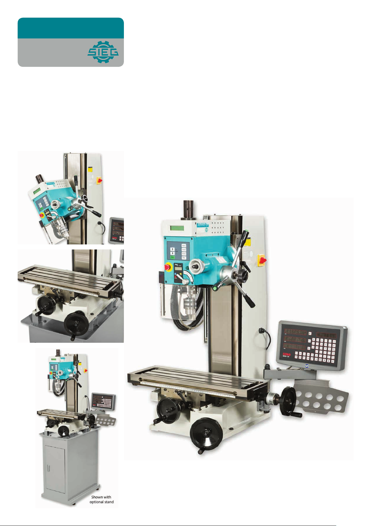
Super Tilt Head Mill Drill
AXMINSTER
Engineer
SERIES
Code 505106
Original Instructions
AT
: 21/03/2023
BOOK VERSION: 3
Page 2
Cert No: SX3
EU Declaration of Conformity
Axminster Tool Centre Ltd
Axminster Devon
EX13 5PH UK
axminstertools.com
declares that the machinery described:-
Type
Model
Signed
Andrew Parkhouse
Operations Director
Mill Drill
SX3-DIGI
Date: 10/04/2020
This machine complies with the following directives:
2006/42/EC
2014/30/EU
EN 61000-3-2: 2014
EN 61000-3-3: 2013
EN 55014-1: 2017
EN 55014-2: 2015
conforms to the machinery example for which the
EC Type-Examination Certificate No TA 385203413
has been issued by Shanghai SIEG Machinery Co., Ltd
at: No.555 CaoFeng Rd., South to No. 17 Bridge of Caoan Rd., SHANGHAI CHINA
and complies with the relevant essential health and safety requirements.
Page 3

IMPORTANT SAFETY INSTRUCTION
READ ALL INSTRUCTIONS AND WARNINGS BEFORE USING THIS TOOL
Operator
COMMON SENSE AND CAUTION ARE FACTORS WHICH CANNOT BE BUILT INTO
ANY PRODUCT. THESE FACTORS MUST BE SUPPLIED BY THE OPERATOR. PLEASE
REMEMBER:
1. When using electric tools, machines or equipment, basic safety precautions should
always be followed to reduce the risk of fire, electric shock, and personal injury.
2. Keep work area clean. Cluttered areas invite injuries.
3. Consider work area conditions. Do not use machines or power tools in damp, wet, or
poorly lit locations. Do not expose equipment to rain, keep work area well lit. Do not
use tools in the presence of flam-mable gases or liquids.
4. Keep children away, all children should be kept away from the work area.
5. Guard against electric shock. Prevent body contact with grounded surfaces such as
pipes, radiators, ranges, and refrigerator enclosures.
6. Stay alert. Never operate if you are tired.
7. Do not operate the product if under the influence of alcohol or drugs. Read warning
labels on prescriptions to determine if your judgment or reflexes might be impaired.
8. Do not wear loose clothing or jewelry as they can be caught in moving parts.
9. Wear restrictive hair covering to contain long hair.
10. Use eye and ear protection. Always wear.
11. Keep proper footing and balance at all times.
12. Do not reach over or across running machines.
Before operations
1. Be sure the switch is OFF when not in use and before plugging in.
2. Do not attempt to use inappropriate attachments in an attempt to exceed the tool”s
capacity. Approved accessories are available from the dealer or machine maker.
3. Check for damaged parts, before using any tool, any part that appears damaged
should be carefully checked to determine that it will operate properly and perform its
intended function.
4. Check for alignment and binding of all moving parts, broken parts or mounting fixtures
and any other condition that may affect proper operation. Any part that is damaged
should be prop early repaired or replaced by a qualified technician.
5. Do not use the tool if any switch does not turn off and properly
Operation
1. Never force the tool or attachment to do the work of a larger industrial tool. It is
designed to do the job better and more safely at the rate for which it was intended.
2. Do not carry the tool by its power cord.
3. Always unplug the cord by the plug. Never yank the cord out of the wall.
4. Always turn off the machine before unplugging.
2
Page 4

IF THERE IS ANY QUESTION ABOUT A CONDITION BEING SAFE OR UNSAFE, DO
NOT OPERATE THE TOOL!
Grounding Instructions
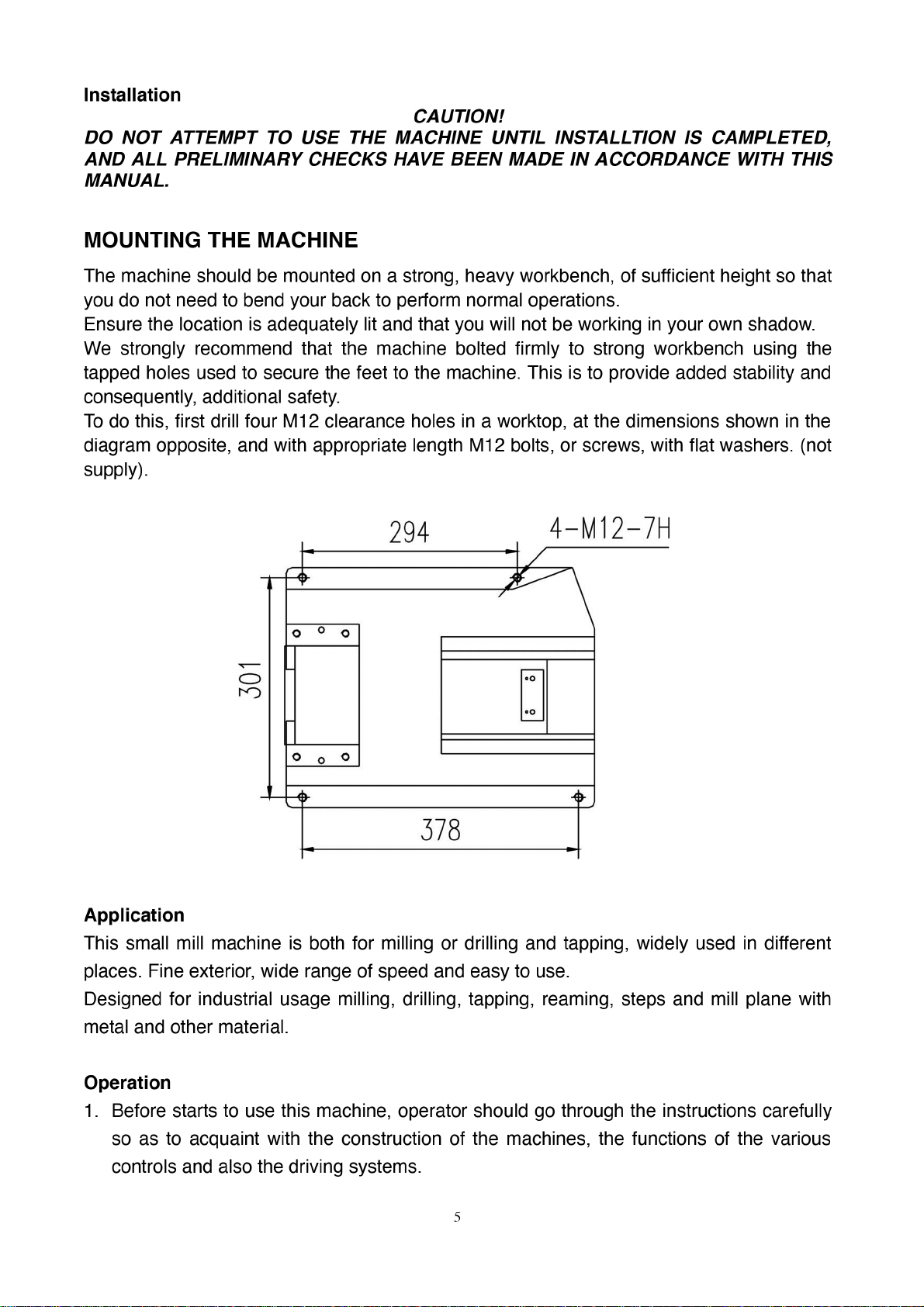
This machine has a three-prong plug, the third prong is the ground. Plug this cord only
into a three-prong receptacle. Do not attempt to defeat the protection the ground wire
provides by cutting off the round prong. Cutting off the ground will result in a safety hazard
and void the warranty.
DO NOT MODIFY THE PLUG IN ANY WAY. IF YOU HAVE ANY DOUBT, CALL A
QUALIFIED ELECTRICIAN.
Specification˖˖˖˖
Max. drilling capacity: 25 mm
Max. tapping capacity: 12 mm
End mill capacity 16 mm
Face mill capacity 50 mm
Spindle stroke 70 mm
Throat 230 mm
Max. distance spindle to table 350 mm
Spindle taper MT#3 or R8
Spindle speed
100-1750 rpm f10%
Table effective size 550x160 mm
T-slot size 12 mm
Table cross travel 160 mm
Table longitudinal travel 300 mm
Motor output power
Overall dimension(LxWxH)
1000 W
685x560x830 mm
Weight (Net/Gross) 165 / 198 Kg
Packing size (LxWxH) 840x820x1040 mm
Unpacking & Preparing for Use
Before unpacking you must check the package carefully, to find whether it is damaged and
any may have effect on the machine, please connect with the distributor in advance.
Unpacking carefully, check the species of standard accessories and the quantity to find
whether it is as same as the packing list in the package.
3
Page 5
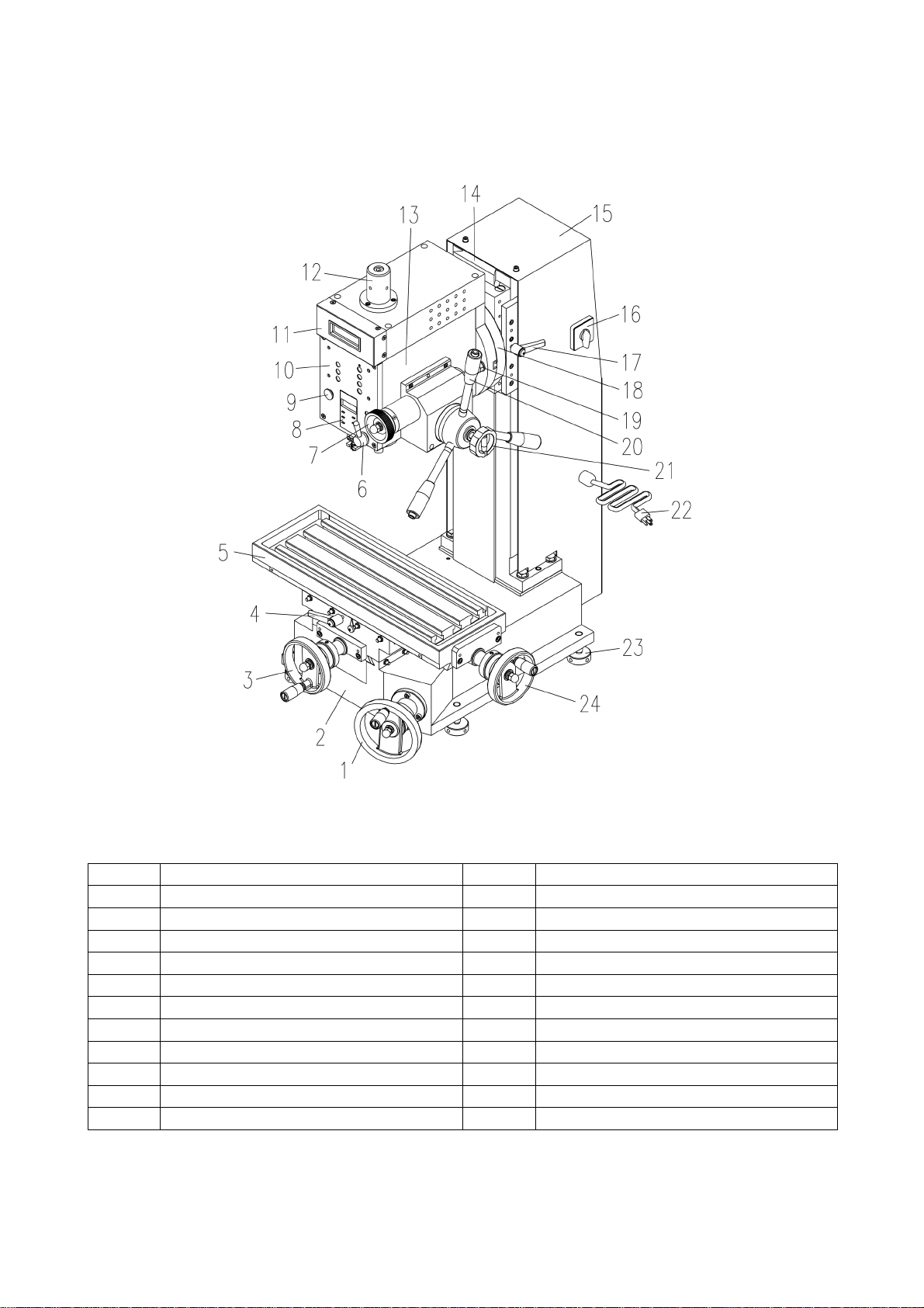
FEATURE
1 Lifting handwheel 13 Spindle box
2 Base 14 Fuselage
3 Cross feed handwheel 15 Cover for fuselage
4 Lock handle 16 Power switch
5 Worktable 17 Lock handle
6 Spindle lock handle 18 Rotate connect plate
7 Fine feeding handwheel 19 Lock bolt
8 Depth display 20 With tapping handle
9 Emergency stop switch 21 Fine feeding lock handle
10 Touch Switch panel 22 Power plug
11 Rotate speed display 23 Adjust bolt
12 Protective cover 24 Longitudinal handwheel
4
Page 6
Page 7
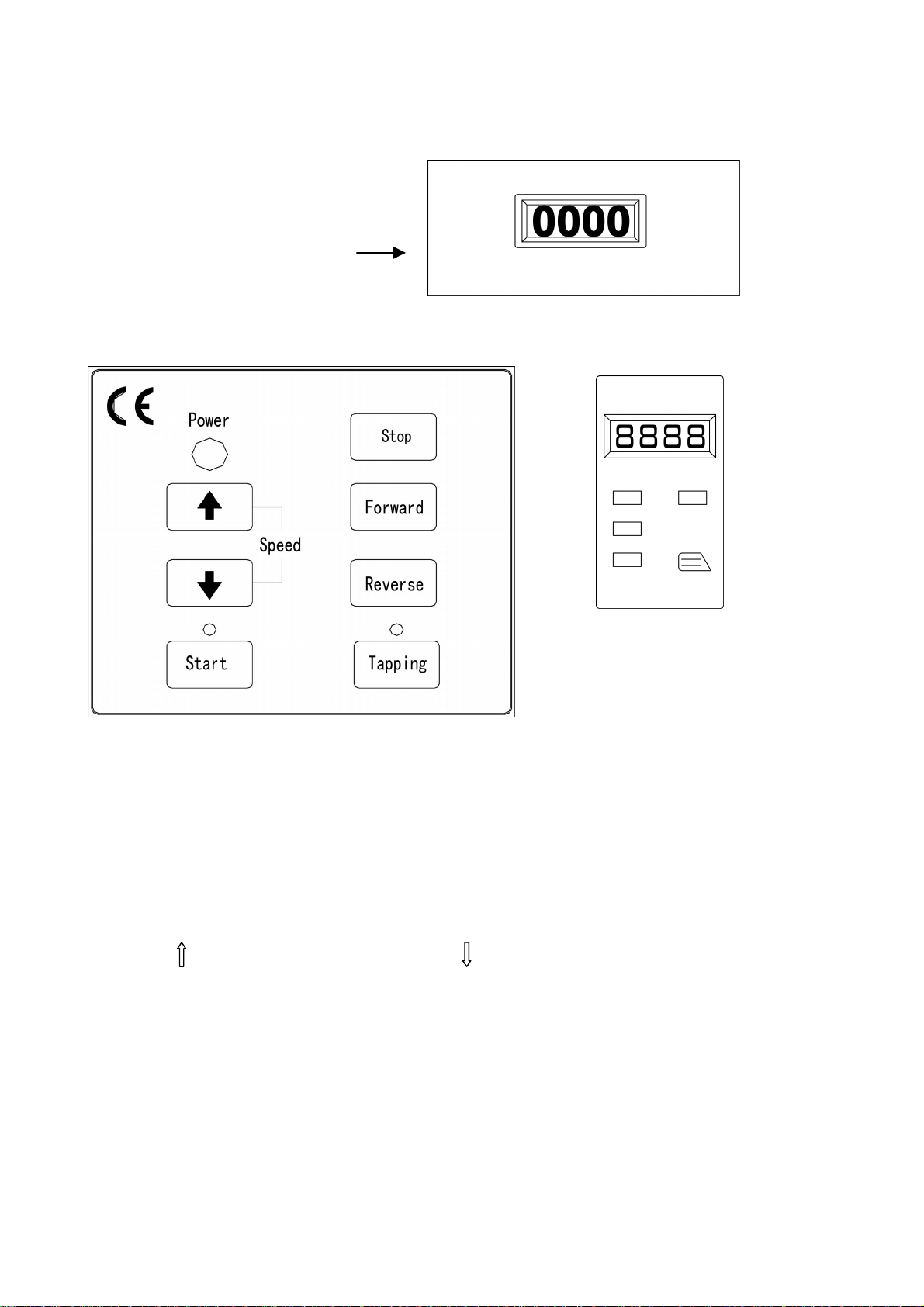
2. This machine uses touching button (see operation panel below), operating steps refer
to the flow chart.
Spindle speed readout
Operation panel Spindle depth readout
Operating steps
1. Insert the electric plug into its socket. Turn the power switch (on left) to ‘I’ position, the
power indicator lights (green, in front of the spindle box).
2.
Release the Emergency stop switch by turning the round head of the switch, the
Spindle speed readout shows ‘0000’.
3.
Press ‘Start’ button on the touching panel, the light above ‘Start’ button lights, spindle
speed readout shows ‘0100 FORWARD’. Notice:‘0100’ is the lowest speed of this
machine.
4. Press ‘ ’ button, speed increase, press ‘ ’ button , speed decrease.
5. Press ‘Stop” button, spindle stop running, if press ‘Start’ button now, spindle runs to the
speed last setting automatically.
6. Press the “Tapping” button, the light above the ‘Tapping’ button lights. This means now
is the ‘Tapping mode’, ‘Forward’ and ‘Reverse’ buttons are unavailable
6
Page 8
Page 9
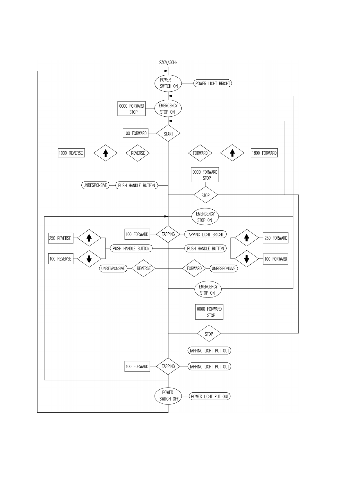
Flow chart
8
Page 10
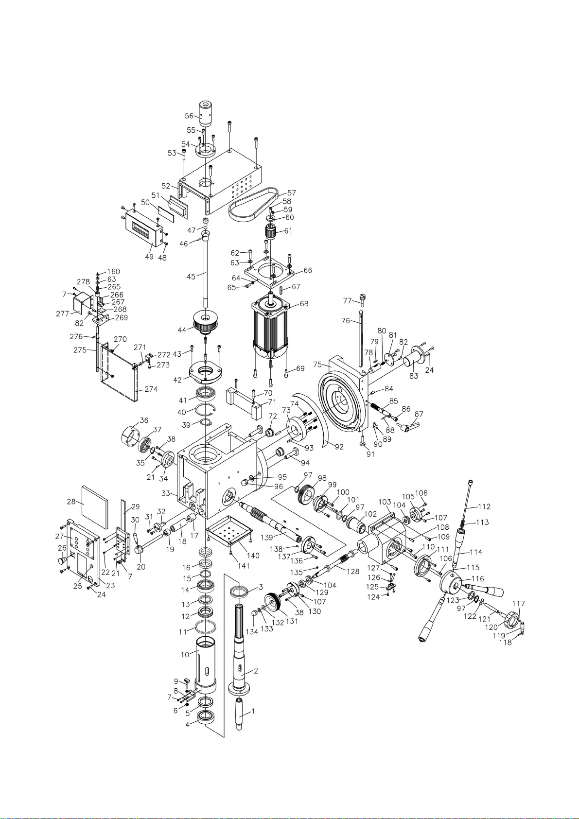
Parts drawing ( I )
9
Page 11
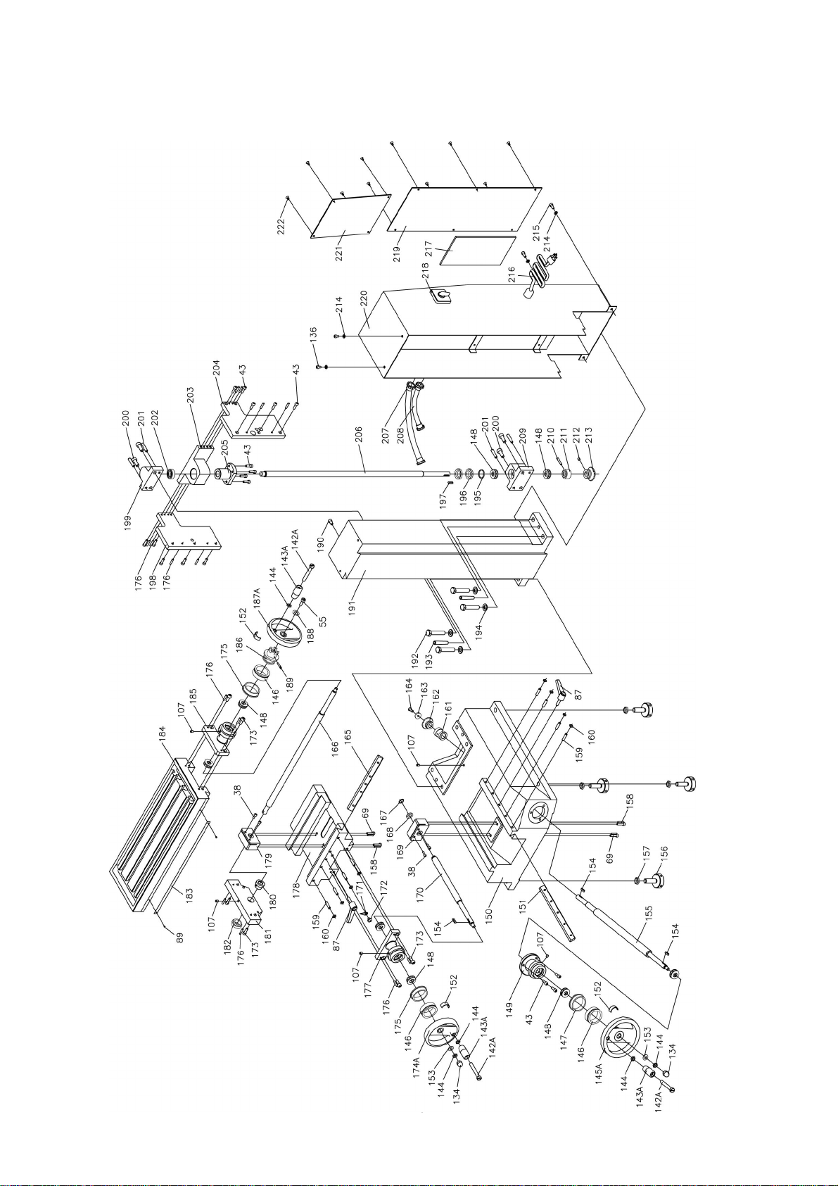
Parts drawing ( II )
10
Page 12

Parts list I
No. Description Q’ty No. Description Q’ty
1 Taper shank
2 Spindle
3 Under oil seal I
4 Taper bearing 32907
5 Under oil swal II
6 Nut M5
7 Screw M3x8
8 Display fixed bracket
9 Square screw
10 Spindle sleeve
11 Sleeve limit pad
12 Bearing 8106
13 Upper washer II
14 Bearing 80106
15 Upper washer I
16 Small round nut M27x1.5
17 Spindle brake sleeve II
18 Spindle brake sleeve I
19 Deep washer
20 Lock bolt
21 Spring round pin 3x8
22
Screw M3x8 4
23
Switch panel 1
24 Screw M4x16
25 Indicator light
26 Emergency stop switch
27 Touch panel
28 PC Board
29 Electron display
30 Small handle
31 Screw M3x10
32 Spindle sleeve orientation shaft
33 Spindle box
34 Left support flange
35 Check ring 16
36 Check spring cover
37 Clockwork spring
38 Screw M4x12
10
40 Check ring 65
1
41 Bearing 80107
1
42 bearing seat
1
43 Screw M5x16
1
44 Synchronization pulley
1
45 lock bolt
2
46 Taper pin 3x18
4
47
1
1
1
1
1
1
1
1
2
1
1
1
1
3
7
1
1
1
1
1
1
2
1
1
1
1
1
1
Screw M10x16 1
48
Screw M4x6 6
49
Cover 1
50
Block piece 1
51 Rotate speed display
52 Spindle box cover
53
Screw M6x40 4
54 Dustproof cover I for spindle
55 Screw M4x10
56 Dustproof cover II for spindle
57 Timing belt
58 Screw M6x16
59 Pin 3x10
60 Washer
61
Motor timing pulley 1
62
Screw M6x20 4
63 Washer 6
64 Nut M5
65 Bolt M5x25
66
Motor support plate 1
67 Key 5x25
68 Brushless motor
69
Screw M5x20 8
70
Screw M4x35 2
71 Spindle box paneling
72 Orientation steel sleeve
73
Rub circle 1
74 Compress spring 1x6x20
75 Vertical slide
76 Tilted wedge
77 Adjusting screw
1
1
1
21
1
1
1
1
1
1
4
1
1
1
1
1
4
1
1
1
1
1
2
6
1
1
1
39 Check ring 35 1 78 orientation small gear shaft 1
11
Page 13

No. Description Q’ty No. Description Q’ty
79 Key 4x12 1 119
80 Compress spring 0.7x4.7x25 1 120
81
Cover board 1
82
Screw M4x10 3
83
Center orientation shaft 1
84 Screw M6x8 1 124
85
Small gear shaft 1
86 Inlay shaft 1 126
87 Small handle assembly 3 127
88 Taper pin 3x10 1 128
89 Scutcheon rivet 4 129 Worm adjust mat
90 indication brand 1 130
91 Adjust screw 1 131
92
Staff guage 1
93
Pin 5x20 2
94
T screw 2
95 Washer 10 2 135
96 Cap nut M10 2 136
97
Check ring 20 3
98
Tilted gear 1
99
Fastness sleeve 1
100
Screw M4x16 3
101
Washer I 1
102
Guide electricity assembly 1
103
Worm support box 1
104
Bearing 8101 2
105
Worm right support flange 1
106
Screw M4x10 6
107
Cup oil 6 7
108
Screw 6x20 1
109
Screw M5x16 2
110
Screw M5x20 2
111
Right support flange II 1
112
Joy stick 3
113
Compress 0.7x6x25 3
114
Handle assembly 3
115
Check ring 4 3
116
Big handle seat 1
117
Small magnetism block 1
142A
143A
145A
Assistant small handle 1
Worm wheel lock handle 1
121
lock small shaft 1
122
Steel ball 8 3
123
Adjust mat 1
Screw M3x6 2
125
Touch fastness fight 1
Guide electricity bar 1
Screw M3x6 1
Worm 1
1
Worm left support flange 1
Worm handwheel 1
132 Washer 8
133 Nut M8
134 Cup nut M8
1
1
3
Key 4x10 1
Screw M5x12 5
137
Right support flange I 1
138 Key 6x8
139 Gear shaft
140
Spindle box below cover 1
141 Screw M4x10
3
1
4
Screw M8x75 3
Handle sleeve 3
144
Nut M8 5
Handle wheel 1
146
Dial 3
147
Inlay circle 1
148
Bearing 51101 8
149
Support flange 1
150
Base 1
151
Cross wedge 1
152
Reed 3
153
Washer 8 2
154 Key 4x16
155
Rotate shaft 1
156
Adjust bolt 1
157
Nut M12 4
3
118 Pin 3x14 1 158 Taper pin 3x20 4
12
Page 14

Parts list ( III )
No. Description Q’ty No. Description Q’ty
159 Screw M6x25 8 199 Upper bearing seat 1
160
Nut M6 8
161
Shaft sleeve 1
162
Taper gear 1
163
Washer 1
164
Screw M5x14 1
165
Portrait wedge 1
166
Portrait leadscrew 1
167
Check ring 12 1 207 Tube connecter 4
168
Washer 1 208 Tube 2
169
Cross leadscrew nut 1 209 Below bearing seat 1
170
Cross leadscrew 1 210 Taper pin 4x26 1
171
Finger 1 211 Limit sleeve 1
172
Screw M6x6 1 212 Set screw M5x8 1
173
Screw M6x16 6 213 Taper gear II 1
174A
187A
Handwheel 1 214 Washer 5 4
175
Inlay circle 2 215 Screw M5x8 2
176
Taper pin 4x20 14 216 Power line 1
177
Bearing Seat 1
178
Saddle 1
179
Portrait leadscrew nut 1
180
left bearing sleeve 1
181
Left support 1
182
Left support stop up 1
183
Staff guage 1
184
Work table 1
185
Portrait leadscrew bearing seat 1
186
Leadscrew clutch 1
Handwheel 1
188
Washer 1
189
Pin 4x28 1
200
Screw M8x20 4
201
Taper pin 6x30 4
202
Bearing 80101 1
203
Support fight 1
204
Side support plate I 1
205
Verticality leadscrew nut 1
206
Verticality leadscrew 1
217
PC Board 1
218
Power switch 1
219
Cover II 1
220
Back cover 1
221
Cover I 1
222
Screw M4x5 10
*265 Compress spring 1.4x8.2x24 1
*266 Screw M2x10 2
*267 Micro switch 1
*268 Insulation washer 20x27 1
*269 Support plate 1
*270 Screw M4x8 3
*271 Magnet block 1
190 Screw M6x10 1 *272 Block 1
191
Verticality lead rail 1
192
Bolt M10x50 4
193
Taper pin 6x40 2
194
Washer 10 4
195
Washer 1
196
Small round nut M16x1.5 2
197
Key 4x20 1
198 Side support plate II 1
13
*273 Screw M4x10 1
*274 Protect cover 1
*275 Rotate shaft 1
*276 Round pin 3x8 1
*277 Cover 1
*278 Spacer 1
Notice
Cover for drill chuck (these parts is optional parts)
: the parts with “*” means use for Protective
Page 15
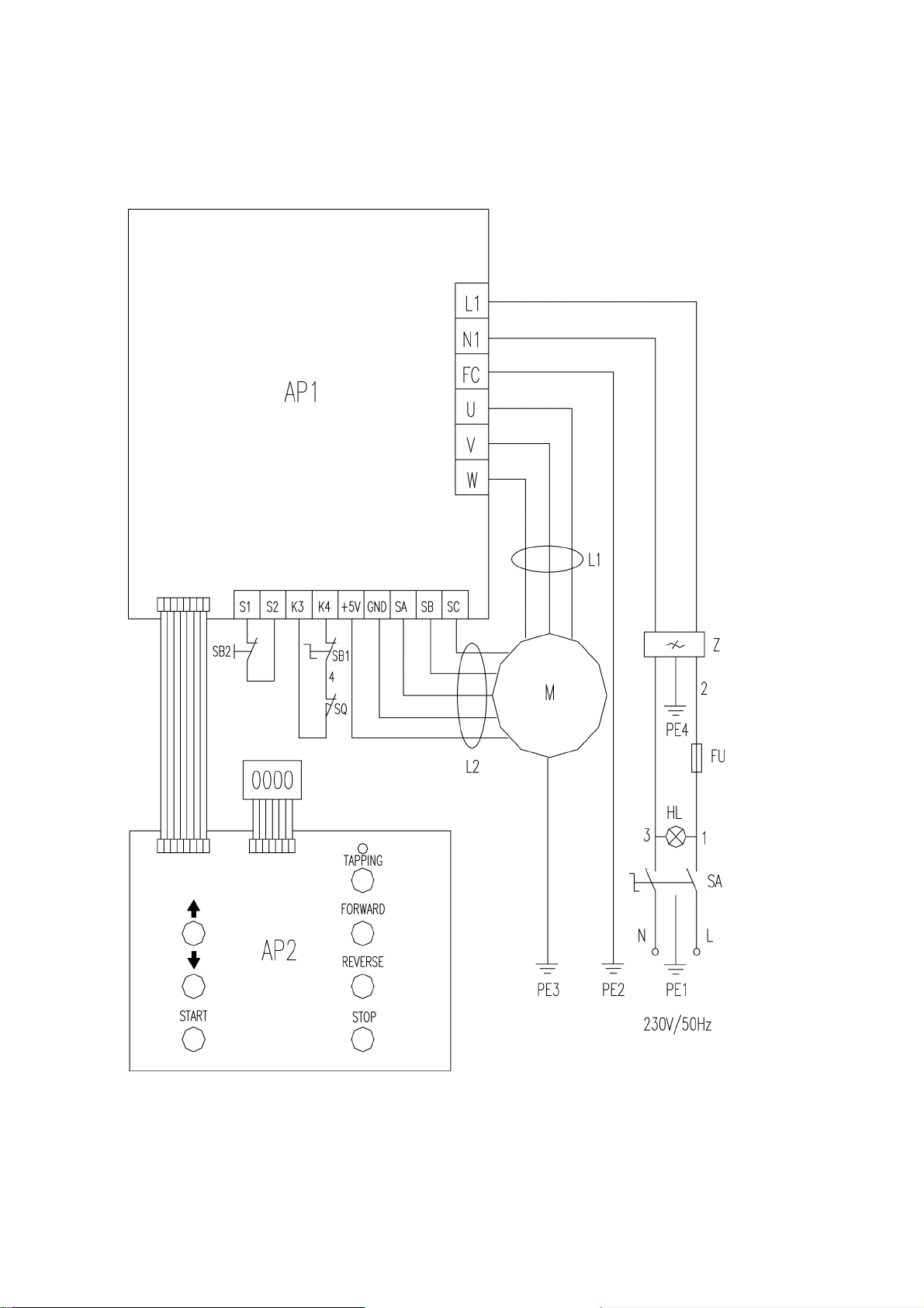
Circle drawing (230V)
14
Page 16
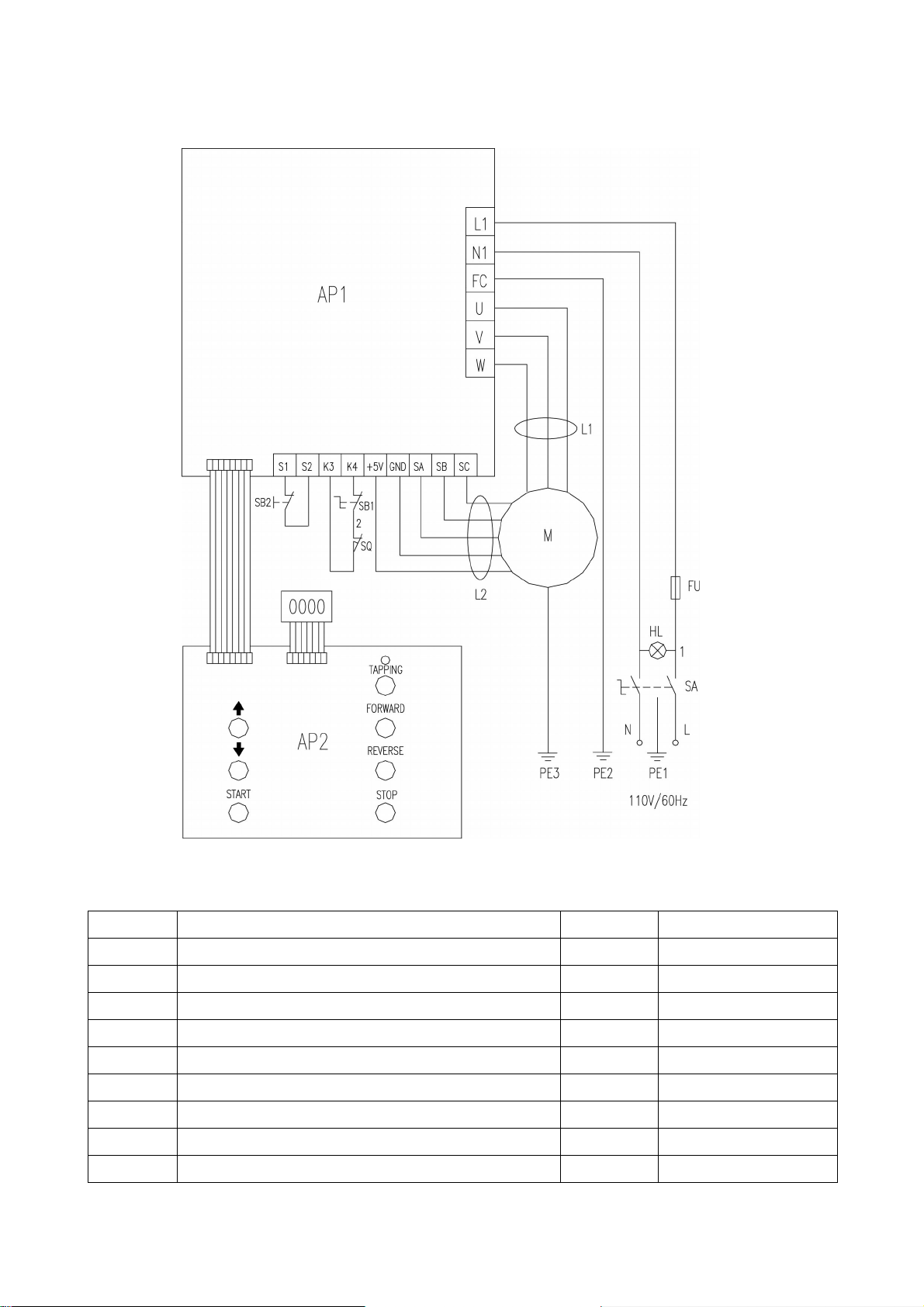
Circle drawing (110V)
Packing List
No. Description Q’ty Remarks
1 Drill chuck with taper shank and key 1
2 L Hex. Wrench S:3,4,5,6, 4
3 Double end wrench: 8x10; 14x17;17x19 3
4 Oil cup 1
5 T-nut 2
6 L Hex. Wrench assembly 1
7 Lock wrench 1
8 Fuse 1
9 manual 1
15
Page 17

Page 18

The Axminster guarantee
Buy with confidence from Axminster!
So sure are we of the quality, we cover all parts and labour free of charge for three years!
For more information visit axminstertools.com/3years
The packaging is suitable for recycling.
Please dispose of it in a responsible manner.
EU Countries Only
Do not dispose of electric tools together with household waste material.
By law they must be collected and recycled separately.
Axminster Tools, Axminster Devon EX13 5PH
axminstertools.com
 Loading...