


900118,810165
SSBP 305mm &
RTC7030 750mm
Sheet Metal Workers
Axminster Reference No: RTC7030 (810165)
Axminster Reference No: SSBP (900118)
User Manual
WHITE
AXMINSTER
W
www.axminster.co.uk
SSBP (900118)
RTC7030
(810165)

WHITE
AXMINSTER
W
Index of Contents...
Page No.
01
Safety Protection Symbols
SAFETY!!
!
The symbols shown on the cover of this
manual advise that you wear the correct
safety protection when using this machine.
E
y
e
P
r
o
t
e
c
t
i
o
n
S
a
f
e
t
y
H
e
l
m
e
t
P
r
o
t
e
c
t
i
v
e
G
l
o
v
e
s
S
a
f
e
t
y
F
o
o
t
w
e
a
r
R
e
s
p
i
r
a
t
o
r
S
a
f
e
t
y
V
i
s
o
r
R
e
a
d
M
a
n
u
a
l
T
w
o
M
a
n
A
s
s
e
m
b
l
y
E
a
r
D
e
f
e
n
d
e
r
s
D
u
s
t
M
a
s
k
Index of Contents...........................................................................................................................01
Declaration of Conformity
………….………........……..…………............................................... 01
What’s in the Box………….………........……..…………................................................................. 02
General Safety Instructions............................................................................................03
Specific Safety Instructions............................................................................................03
Specifications
….………........……..…………............................................................................... 04
Assembly Instructions
….………........……..………….................................................................04
Illustration & Parts Description.................................................................................................05-06
Operating Instructions
………........……..…………..................................................... 07-08-09-10
Adjustments to the Sheet Metal Worker........................................................................................11
Maintenance...................................................................................................................................12
Parts List.........................................................................................................................................13
Parts Breakdown............................................................................................................................14
PLEASE NOTE: THE IMAGES IN THIS MANUAL SHOW THE SSBP
SHEET METAL WORKER, THE RTC7030 IS EXACTLY THE SAME
BUT ON A LARGER SCALE.
!
KEEP HANDS AWAY
FROM ROLLERS!
!
!
KEEP HANDS AWAY
FROM DIE PRESS!
Die
HEAVY
kg
THE MACHINE IS A HEAVY
PIECE OF EQUIPMENT. YOU
ARE ADVISED TO SEEK
HELP BEFORE YOU
ATTEMPT TO LIFT
OR MOVE THIS MACHINE.
WARNING!

WHITE
AXMINSTER
W
02
Whats in the Box...
Model Number: SSBP
1 off: (A) 305mm Sheet Metal Worker
2 off: (B) Support Rods
1 off: (C) Backstop Bar
2 off: (D) Support Blocks
2 off: (E) Support Locking Knobs
1 off: Instruction Manual
1 off: Guarantee Card
Model Number: RTC7030
1 off: (A) 750mm Sheet Metal Worker
2 off: (B) Support Rods
1 off: (C) Backstop Bar
2 off: (D) Support Blocks
2 off: (E) Support Locking Knobs
1 off: Instruction Manual
1 off: Guarantee Card
A
B
C
D
E
A
Fig 1

03
WHITE
AXMINSTER
W
General Safety Instructions...
www.axminster.co.uk
Good Working Practices/Safety
The following suggestions will enable you to observe good working
practices, keep yourself and fellow workers safe and maintain your tools and
equipment in good working order.
• Mount the machine on a flat level bench or surface. Secure the machine to the surface where
applicable.
• Always use machines in an uncluttered area. To reduce the risk of accidents, avoid leaving
materials or other items within the working area and allow clear access to all machine parts
and controls.
• Clean machines by wiping with a oily rag. Do not use solvents or cleaners that may
cause damage to painted/coated surfaces.
• When storing or leaving the machine for any length of time, spray bare metal surfaces
with a protective spray to minimise surface corrosion.
• Before using the machine, ensure that all locking-nuts, chucks etc, are tightened and
secure. Check that all loose keys, spanners etc. have been removed.
• Always ensure that long hair is tied back or retained by a band, hat or safety helmet. Remove all
loose jewellery to prevent it from catching in rotating machinery.
• Always check that the correct machining or cutting speed has been selected.
• Do not operate machine when tired or under the influence of alcohol, drugs or certain medicines.
• WHEN USING THE MACHINE ALWAYS WEAR THE APPROPRIATE EYE PROTECTION, EAR
DEFENDERS AND DUST OR FUME INHALATION PROTECTION.
WARNING!!
!
KEEP TOOLS AND EQUIPMENT OUT
OF THE REACH OF YOUNG CHILDREN
Specific Safety Instructions...
• Ensure that the machine is bolted firmly to a workbench before starting work.
• Keep fingers away from the rollers, the bending dies and the shearing blades.
• Do not wear loose clothing which might get drawn into the machine.
• Keep the top cover closed when the rollers are not in use.
!

WHITE
AXMINSTER
W
04
Specifications...
Axminster No. SSBP RTC7030
900118 810165
Shearing Capacity:
Bending Capacity:
Rolling Capacity:
Width of Bending Fingers:
Diameter of Rolls:
Overall L x W x H:
Weight:
Steel 0.5mm, Aluminium 1.5mm
Steel 0.5mm, Aluminium 1.5mm
Steel 1.0mm, Aluminium 1.5mm
25, 50, 75 & 102mm
38mm
380 x 420 x 300mm
46kg
Steel 0.8mm, Aluminium 1.5mm
Steel 0.8mm, Aluminium 1.5mm
Steel 1.0mm, Aluminium 1.5mm
25, 51, 75, 152, 203 & 254mm
38mm
1,020 x 410 x 510mm
130kg
Assembly Instructions ...
The bender comes secured to the base of the crate with four bolts; these bolts can be used
for mounting the bender to the workbench for safe and convenient operation.
The operating handle can be mounted on either side of the machine. To re-position the
handle remove the handle securing plate (see fig 2 & 2a), transfer the handle to the other
side and replace both retaining plates.
Handle
5mm Hexagon key
Grease nipple
Handle securing plate
Handle locking knob
Hex bolt
Fig 2
Fig 2a

05
WHITE
AXMINSTER
W
Illustration & Parts Description...
Cover
Lower roller
Roller clearance adjusting keys
Handle arm
Handle
Handle locking
knob
Lower bending die
Right frame
casting
Cranking arm
Pressure plate
Work surface
Guide block
Upper roller
Upper bending die
Left frame
casting
Fig 3
Roller cover

WHITE
AXMINSTER
W
06
Illustration & Parts Description...
FREEPHONE 0800 371822
Lower roller
adjusting knobs
Cross beam
Back stop
Back stop
support block
Back stop
support rods
Cranking arm
Adjustment bar
Adjustment
bolt
Fig 4
Upper roller
Lower roller

WHITE
AXMINSTER
W
Operating Instructions...
The basic operation of the machine is as follows. The operating handle is attached to a
shaft which serves two functions; firstly it drives the three rollers which carry out the rolling
operation and secondly, with the aid of eccentrics, mounted at the two ends, it raises and
lowers the lower cross bar of the machine. Mounted on the top of this cross bar are the
female bending dies whilst the lower edge carries the upper shear blade. The male bending
dies are fixed to the static cross beam and the lower shear blade is fixed to the table on
which the work is supported. Thus, as the handle is operated, the rolls rotate to form
cylindrical items whilst the main beam goes up and down to either form bends between the
two dies or to shear material between the moving and fixed blades.
Shearing
Shearing can be carried out either by positioning the material between the blades by eye
using a line marked on the sheet or by using the adjustable backstop for more precise
results.
To fit the backstop assembly, screw the two rods into the rear of the static cross beam
(see fig 5), fit the two blocks to the backstop bar with two hex screws (see fig 6) and slide
the bar onto the two rods (see fig 7). The two clamping screws are used to secure the
backstop in the required position on the two rods. Please note that the flange of the
backstop bar should be positioned downwards.
If a precise 90 deg angle is required, the guide block can be fitted to the right hand side of
the table using hex screws. (see fig 8). The guide block should be set square to the lower
blade using an engineer’s square.
To carry out the shearing operation, raise the cross beam to its highest position, slide the
material in between the blades, position it correctly either with the marked line or up against
the back stop and rotate the operating handle to make the cut.
NOTE: If you find that the rollers are not rotating all the way round while sheet
bending, it’s because the pressure plate that clamps the material during
shearing, binds up on it’s springs & the handle can not be turned completely
over. If this accrues, remove the pressure plate.
Bending
As with the shearing operation, bending can either be carried out by lining up the work by
eye or by positioning it with the help of the backstop. If the backstop is to be used it should
be positioned in the upper holes (see fig 7) and the backstop bar reversed so that the
flange is upwards.
Having positioned the workpiece correctly between the bending dies, rotate the handle to
bring the dies together to form the bend. The angle of the bend, up to a maximum of 90
deg., is controlled by limiting the travel of the upper die. If repetition work is to be carried
out then the bend angle can be set by adjusting the height of the cross beam using
adjusting screws shown (see fig 9b).
If it is required to bend only part of the workpiece, as shown in fig. 9, then the appropriate
sections of the upper die can be removed by undoing the hex bolts (see Fig. 9a). When
forming this type of bend it will be necessary to notch the corner as shown in figs 10 & 10a
to achieve the required result.
!
07

WHITE
AXMINSTER
W
Operating Instructions...
Rolling
Start by removing the cover which protects the rollers then lower the rear roller by
slackening off the adjustment screws. (see figs 11 & 12) (see page 10)
Insert the workpiece between the upper and lower rollers and close up the gap between the
rollers using the adjusting screws, (fig 3), until there is a very slight clearance between the
workpiece and the rollers.
Lower the bottom roller using the adjustment knobs (see fig 12) then advance the
workpiece through the rollers by rotating the operating handle until contact is made with
the rear roller. Adjust the rear roller so that the work is slightly deformed as it passes
through the rollers. Make a series of passes through the rollers, closing up the rollers each
time, until the required diameter is achieved. The amount of bend that can be achieved per
pass through the roll depends on the type and thickness of the material being formed. (see
fig 13) (see page 10)
Wire can be rolled into rings by using one of the three grooves at the end of the rollers
(see fig 14).
Alternative position for backstop bar
Shearing Illustrations
Back stop
Support block
Clamping
screw
2 hex bolts
Back stop
Fig 5
Fig 6
Fig 7
08

09
WHITE
AXMINSTER
W
Operating Instructions...
Guide block
Hex bolt
This part of the die
has been removed
Notch
corners
Bending Illustrations
Workpiece
Bolt
Hex screw
Fig 8
Fig 9
Fig 9a
Fig 10
Fig 10a
Fig 9b
!
KEEP HANDS AWAY
FROM DIE PRESS!
Die

WHITE
AXMINSTER
W
Operating Instructions...
10
Grooves for wire
and rod bending
Lower roller
Upper roller
Workpiece
Roller cover adjustment
screw, one each end of
casting
Lower roller adjustment
knobs
Rear roller
Rolling Illustrations
Fig 14 Fig 13
Fig 12
Fig 11
KEEP HANDS AWAY
FROM ROLLERS!
!

11
WHITE
AXMINSTER
W
Adjustments to the Sheet Metal Worker...
Shear bow
Over a period of time the frame which carries the lower shear blade may go out of
alignment, resulting in shear cuts which are not straight. To correct this problem, the bolt
attached to the adjusting bar should be adjusted; tightening the bolt will cause the ends of
the frame to bow outwards whilst loosening it will bring it in (see figs 15 & 16).
Shear Blade Adjustment
To check the alignment of the blades, lower the upper shear blade as far as it will go and
examine the gap between the blades. If one side of the lower shear blade is further away
from the upper blade then the work table will need to be adjusted (see fig 17).
Loosen the screws which secure the work table to the frames and adjust the screws
underneath the table until the two blades meet evenly along their length. Re-tighten the
table securing screw (see fig 17).
Bending Die Adjustment
If t
he line-up of the upper dies becomes uneven for any reason they can be re-aligned. Cut
a piece of hardwood to the same length as the dies, ensuring that opposite faces are flat
and parallel. Raise the upper dies to their highest position, place the wooden gauge on the
lower die, slacken off the clamping screws (see fig 9a) which secure the upper dies and
allow them to r
est on the timber. Check that all the dies are lying flat on the timber and then
re-tighten the bolts securely.
17mm spanner
Adjusting bar
Upper blade
Work table
Gap between
the blade and
work table
Table clamping screws
Table adjusting
screws
Fig 16 Fig 15
Fig 17

WHITE
AXMINSTER
W
12
Maintenance...
• Grease the cranking arms using the grease nipples positioned on the tops of the arm
(see figs 18 & 18a).
• Lightly grease the gears shown in fig 18b.
OIL
Fig 18
Fig 18b Fig 18a
13
WHITE
AXMINSTER
W
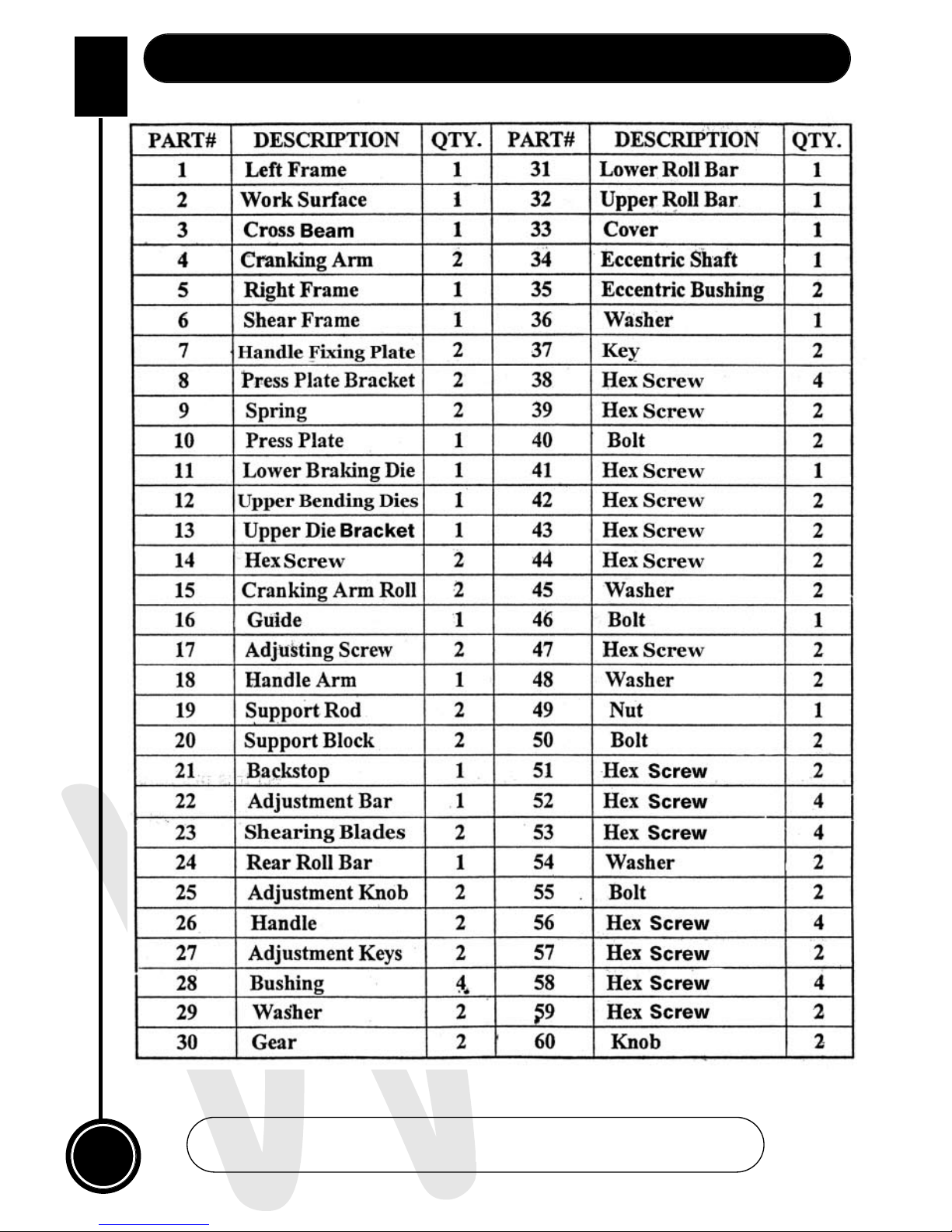
Parts List...
www.axminster.co.uk

WHITE
AXMINSTER
W
14
Parts Breakdown...
FREEPHONE 0800 371822

Axminster Reference No: RTC7030 (810165)
Axminster Reference No: SSBP (900118)
WHITE
AXMINSTER
W
900118,810165
www.axminster.co.uk
Axminster Devon EX13 5PH UK
FREEPHONE 0800 371822
SSBP 305mm & RTC7030 750mm Sheet Metal Workers
Please dispose of packaging for the product in a
responsible manner. It is suitable for recycling. Help to
protect the environment, take the packaging to the local
amenity tip and place into the appropriate recycling bin.
Do not dispose of electric tools together with household
waste material! In observance of European Directive
2002/96/EC on waste electrical and electronic equipment
and its implementation in accordance with national law,
electric tools that have reached the end of their life must be
collected separately and returned to an environmentally
compatible recycling facility.
Only for EU countries
 Loading...