

Page 1
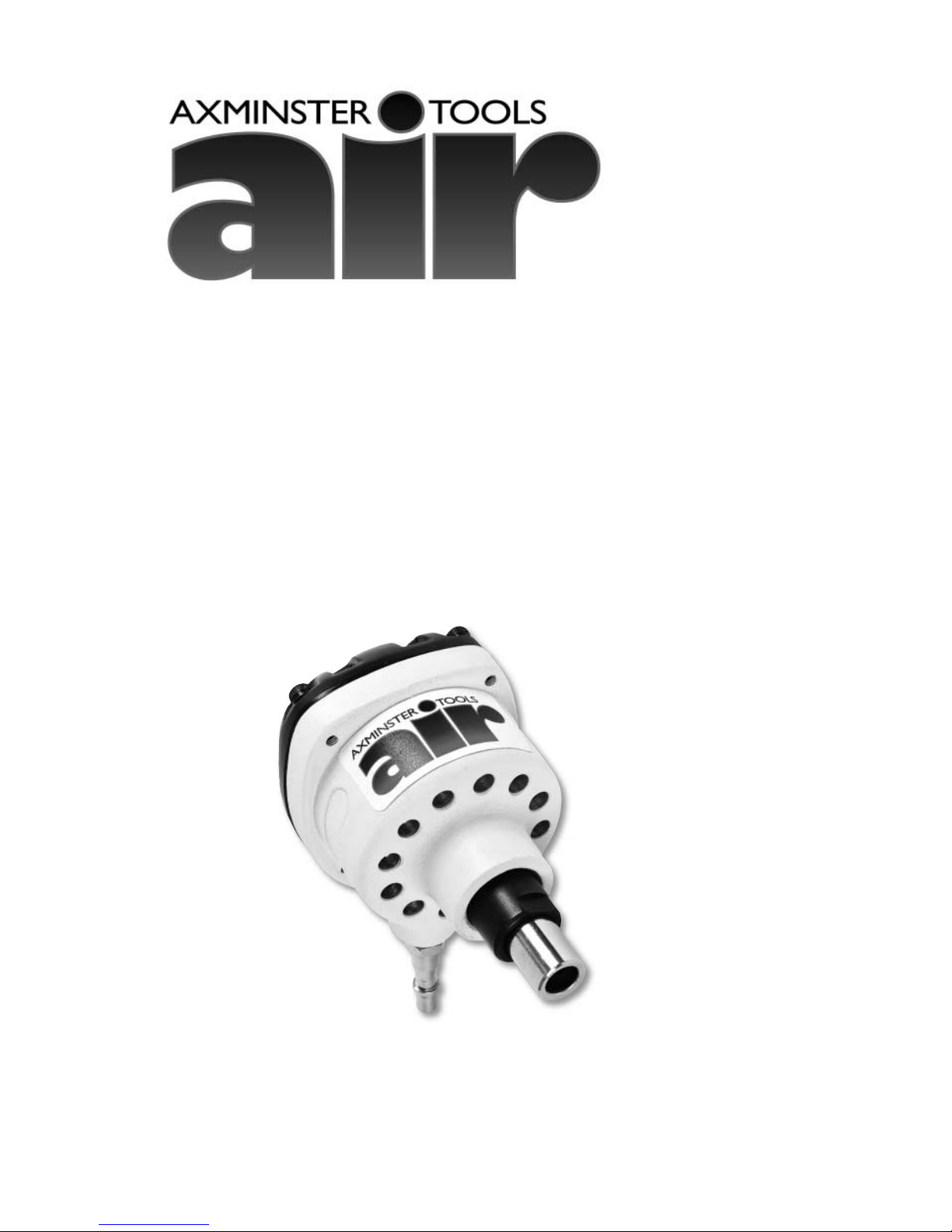
Palm Nailer
A nailer that drives home whatever nails you like.
The nailer fits neatly into the palm of the hand and vibrates at
1,000 blows/min when placed over the top of a nail and gentle pressure applied.
The nail is held in position by the magnetic anvil, the nailer
automatically cuts out when the nail has been driven home.
Supplied with a 1/4" BSP quick release bayonet.
Axminster Tool Centre,
Unit 10 Weycroft Avenue, Axminster, Devon EX13 5PH
www.axminster.co.uk
Page 2

Index of Contents
02
Page No.
Index of Contents.................................................................................................................................................................................2
Declaration of Conformity.................................................................................................................................................................2
What’s in the Box.................................................................................................................................................................................. 3
General Safety Instructions and Recommendations whilst using Air Equipment.............................................3,4,5,6
Specific Safety Instructions for the Palm Nailer.........................................................................................................................6
Specifications..................................................................................................................................................................................... 6,7
Identification and Description of the Air Palm Nailer..............................................................................................................7
Tool Illustration of the Air Palm Nailer...........................................................................................................................8,9,10,11
Preparing your Axminster White Palm Nailer for use........................................................................................................... 12
Using the Air Nailer........................................................................................................................................................................... 12
TroubleShooting.................................................................................................................................................................................13
Maintenance........................................................................................................................................................................................14
llustrated Parts List & Breakdown for the Tacker/Pinner......................................................................................................15
Declaration of Conformity
The undersigned, O.Schiller authorised
by Chong Qing Hong Yuan Pneumatic Tool Factory No.107 Jienan
Street Banan District Chong Qing,
P.R. China
declares that this product:
Model: MSN120
manufactured by Chong Qing Hong Yuan Pneumatic Tool Factory is in
compliance with the standards determined in the following Council
Directive
98/37/EC
Page 3

What’s in the Box
03
Quantity Item Model Number
1 No. Axminster White Palm Nailer with PCL tail fitted. MSN120
1 No. Oil Bottle
1 No. 4mm Allen Key
1 No. Manual
Having unpacked the tool and its accessories,
please check the contents against the equipment
list ”What’s in the box”, if there are any discrepancies,
please contact Axminster Power Tool Centre using
the procedures laid down in the catalogue. Please
dispose of the packaging responsibly; much of the
material is bio-degradable. The tool is plated and
painted to prevent corrosion, so there should be
little or no cleaning required before use.
Please read the Instruction Manual prior to using
your new tool; as well as general precautions and
instructions for use, there are daily and periodic
maintenance recommendations to help you keep
your tool on top line and prolong its life. Keep this
Instruction Manual readily accessible for any others
who may also be required to use the tool.
General Safety Instructions and Recommendations whilst using Air Equipment
Good Working Practices/Safety
The following suggestions will enable you to observe good working practices, keep yourself and fellow
workers safe and maintain your tools and equipment in good working order.
WARNING!! KEEP TOOLS AND EQUIPMENT OUT OF THE REACH OF YOUNG
CHILDREN
Air Powered Tools
!
Work Place/Environment
Keep the tool clean; it will enable you to more easily
see any damage that may have occurred. Clean the
tool with a damp soapy cloth if needs be, do not use
any solvents or cleaners, as these may cause
damage to any plastic components. Check the tool
for damage both before and after work. If damage
has occurred, have it repaired by a suitably qualified
person.
Check the air lines are undamaged, that supply
galleries, spurs or connectors are not leaking.
Keep the work area as well lit and uncluttered as is
practical, this includes personnel as well as material.
Under no circumstances should CHILDREN be
allowed in work areas.
It is good practice to leave the tool disconnected
from the air supply until work is about to
commence, when it is not in use, or unattended.
Once you are ready to commence work, remove any
tools used in the setting up operations (if any) and
place safely out of the way. Re-connect the tool.
Carry out a final check e.g. the connector is tight ‘on’,
the air lines are not leaking, any bits etc, fitted to the
tool are secure, check you have the correct pressure
set, and if you require to move around during the
work operation, that air lines etc, will not ‘snag’.
Page 4

04
General Safety Instructions and Recommendations
whilst using Air Equipment (Continued)
Make sure you are comfortable before you start
work, balanced, not reaching etc., If the work you
are carrying out is liable to generate flying grit,
dust or chips, wear the appropriate safety clothing,
goggles, gloves, masks etc., If the work operation or
environment appears to be excessively noisy, wear
ear-defenders. If you wear your hair in a long style,
wearing a cap, safety helmet, hairnet, even a sweatband, will minimise the possibility of your hair
being caught up in the rotating/moving parts of
the tool, likewise, consideration should be given to
the removal of rings and wristwatches, if these are
liable to be a ‘snag’ hazard. Consideration should
also be given to non-slip footwear, etc.
Do not work with cutting or boring tools of any
description if you are tired, your attention is wandering or you are being subjected to distraction. A
deep cut, a lost fingertip or worse; is not worth it!
Do not work with power tools of any description, if
you are currently taking medication, unless you
have ascertained that your medication will not
cause your judgement or awareness to be
impaired.
Do not use this tool within the designated safety
areas of flammable liquid stores or in areas where
there may be volatile gases. There are very expensive, very specialised machines for working in these
areas, THIS IS NOT ONE OF THEM.
Check that cutters, drills, chisels etc., are the correct
type and size, are undamaged and are kept clean
and sharp, this will maintain their operating
performance and lessen the loading on the tool.
Above all, OBSERVE…. make sure you know what
is happening around you, and USE YOUR
COMMON SENSE.
Installation
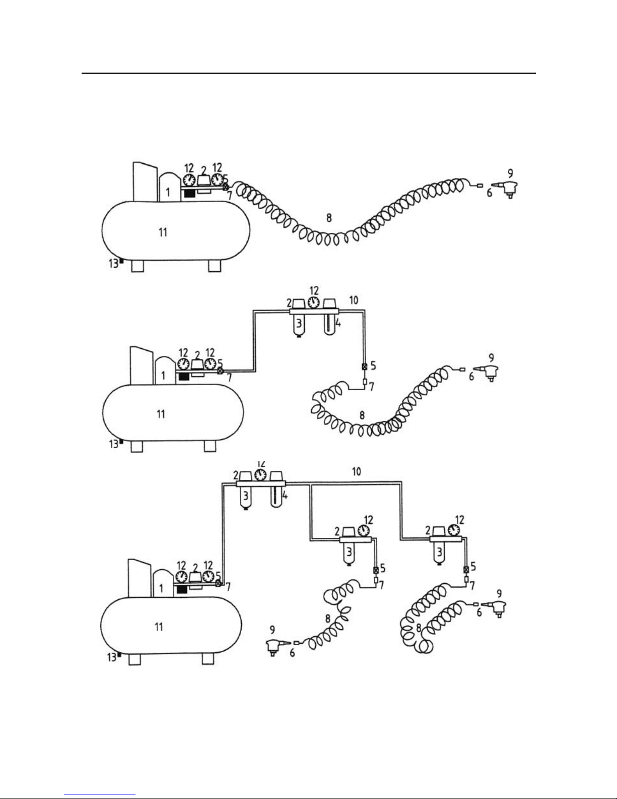
Please study the diagram of an air installation (see opposite page) any new installation
should follow these guidelines. Note. Fixed connectors can be replaced with quick release
connector, but air leakage can cause problems at the ‘connection’ as they become worn.
A) Basic Installation
B) Small Workshop Installation
C) Large Workshop Installation
Legend
1. Compressor
2. Regulator
3. Water trap
4. In line Oiler
5. Shut off valve
6. Quick release connector
7. Fixed connector
8. Air Line
9. Air tool
10. Air Gallery
11. Reservoir
12. Pressure Gauge
13. Water drain
!
Page 5
05
General Safety Instructions and Recommendations
whilst using Air Equipment (Continued)
(A)
(B)
(C)
Basic Installation
Small Workshop Installation
Large Workshop Installation
13
13
13
13
Page 6

06
General Safety Instructions and Recommendations
whilst using Air Equipment (Continued)
General Safety Precautions
Do not use a high pressure air system (greater than
25 bar) to supply power to this tool. Ensure the Air
supply gallery to which your tool is connected has
a pressure regulator controlling the air pressure to
150 psi or less,
and the supply for your tool can be further regulated to the pressure you require.
Never use any form of compressed gas cylinder (air
or any other) to supply power for your tool.
Do not overload the tool or try to use it for a task
for which it was not designed.
Only use the manufacturers spare parts to repair or
refurbish tools and machines.
Be careful not to trip over air lines, be aware of
their locations when they are deployed.
Do not point the tool at people or animals even in
jest.
Use the correct connectors and correctly rated hose
lines to connect your tool to the supply. Only use
proprietary
To avoid water contamination in the system/tools
etc, remember to drain the reservoir tank and the
water traps frequently.
Specific Safety Instructions for the Palm Nailer
If your air system does not use PCL fittings, and
you have reason to change the connecting method
of the tool to your air supply, ensure that the new
connector will not allow pressure to be retained in
the tool.
Ensure the supply does not exceed the maximum permissible pressure
Do not use the nailer to drive nails into hard
materials, e.g. stone, concrete, even using
masonry nails, the striker is not designed to
withstand hardened steel impact.
There is no safety enable with this machine, the
trigger is automatic, and will fire when the striker
face of the piston is depressed (normal by the
nail/fastener that is to be driven). Only use the tool
in the prescribed manner, i.e. between the palm of
the hand and the fastener head.
It is not recommended to use lost head nails.
If a fastener becomes jammed in between the
shroud and the striker, Disconnect the air supply
before attempting to clear the jam.
Specifications
Axminster No 010017
Rating Light Trade
Maximum Operating Pressure 100 psi
Minimum Operating Pressure 70 psi
Air Inlet 1/4" NPT with standard PCL Fitting
Air Consuption (constant nailing 4 CFM)
Maximum Nail Size 4"
Page 7

Specifications (Continued)
07
Weight 0.85 kgs
Footprint (without PCL tail) 80mm wide x 105mm long x 135mm high
Identification and Description of the Air Palm Nailer
Quick release PCL ‘tail’ fitted as standard to the tool. Prior to first use of the day, introduce
(see fig 1) Connector1-2 drops of oil.
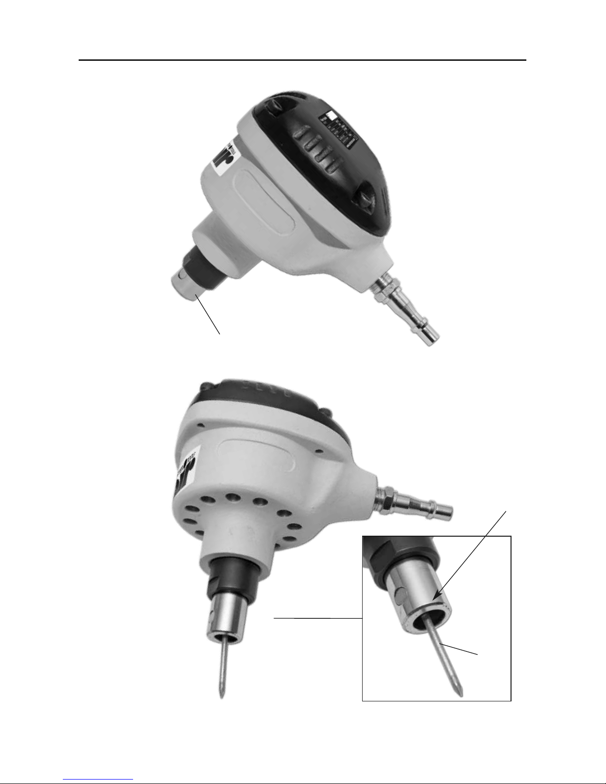
Shroud This is a metal tube that surrounds the striker. It is mounted in the lower body and
(See fig 4) is able to ‘ride’ up and down. It acts against a spring, which gives greater ‘feel’ when
(See Fig 4b) the tool is being pressed down to activate the hammer action. There is a small
magnet buried in the side wall of the shroud, which holds the inserted nail in place
before it is applied to the material. The elliptical, angled hole machined through the
shroud is designed to position and hold a range of headed nails, and bring the axis
of the nails as close to the axis of the striker as possible.
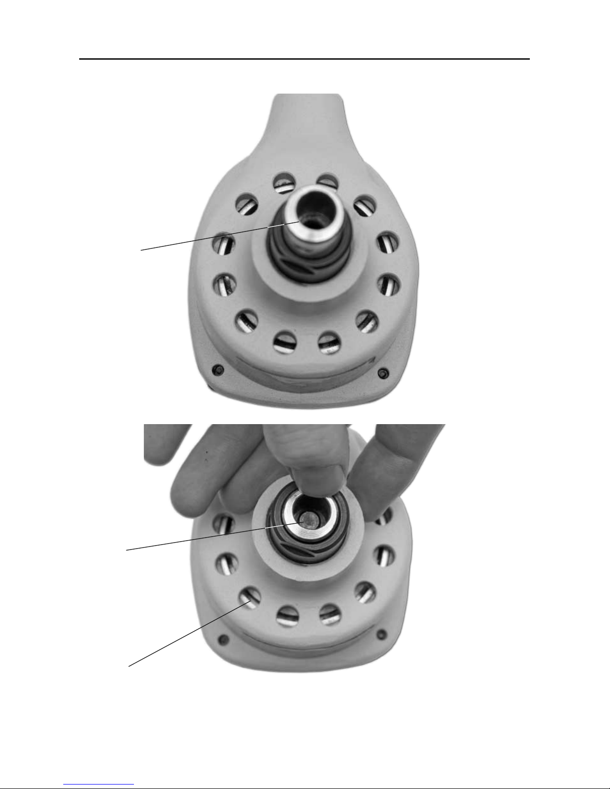
Striker A hardened metal rod attached to the piston in the tool. This is the hammer that
(see fig 3a) drives the nail.
Page 8

Tool Illustration of the Air Palm Nailer
08
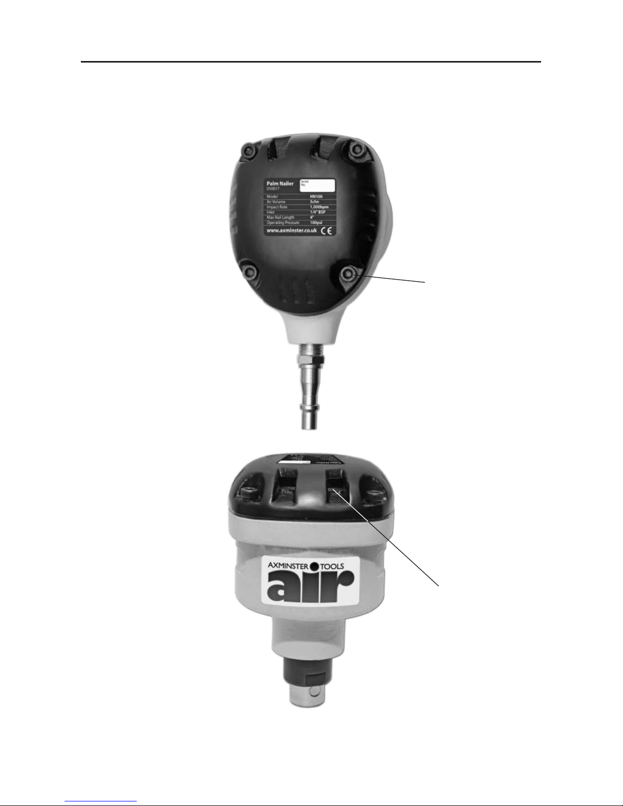
Main body
Exhaust cover
Side View
Back View
Quick release
connector
Fig 1
Fig 1a
Page 9
Tool Illustration of the Air Palm Nailer (Continued)
09
Exhaust vents
(DO NOT COVER)
x4 hex Screws
Top View
Front View
Fig 2
Fig 2a
Page 10
Tool Illustration of the Air Palm Nailer (Continued)
10
Striker
Elliptical hole
Air vents
Fig 3
Fig 3a
Page 11
Tool Illustration of the Air Palm Nailer (Continued)
11
Shroud
Nail
Magnet
Fig 4
Fig 4a
Fig 4b
Page 12

Preparing your Axminster White Palm Nailer for use
Using the Air Nailer
12
Check your air supply system is on, and air is available in the gallery. (Check your in line oilers, if fitted
have
sufficient oil in the reservoirs). Turn on the air to the
hose line. Set the required pressure on the regulator
(We suggest 85 psi).
Note. Remember you have to bleed air through
the regulator to achieve the set pressure, do this
by
opening the hose line using a blow gun or
duster, and setting the regulator whilst the air is
flowing.
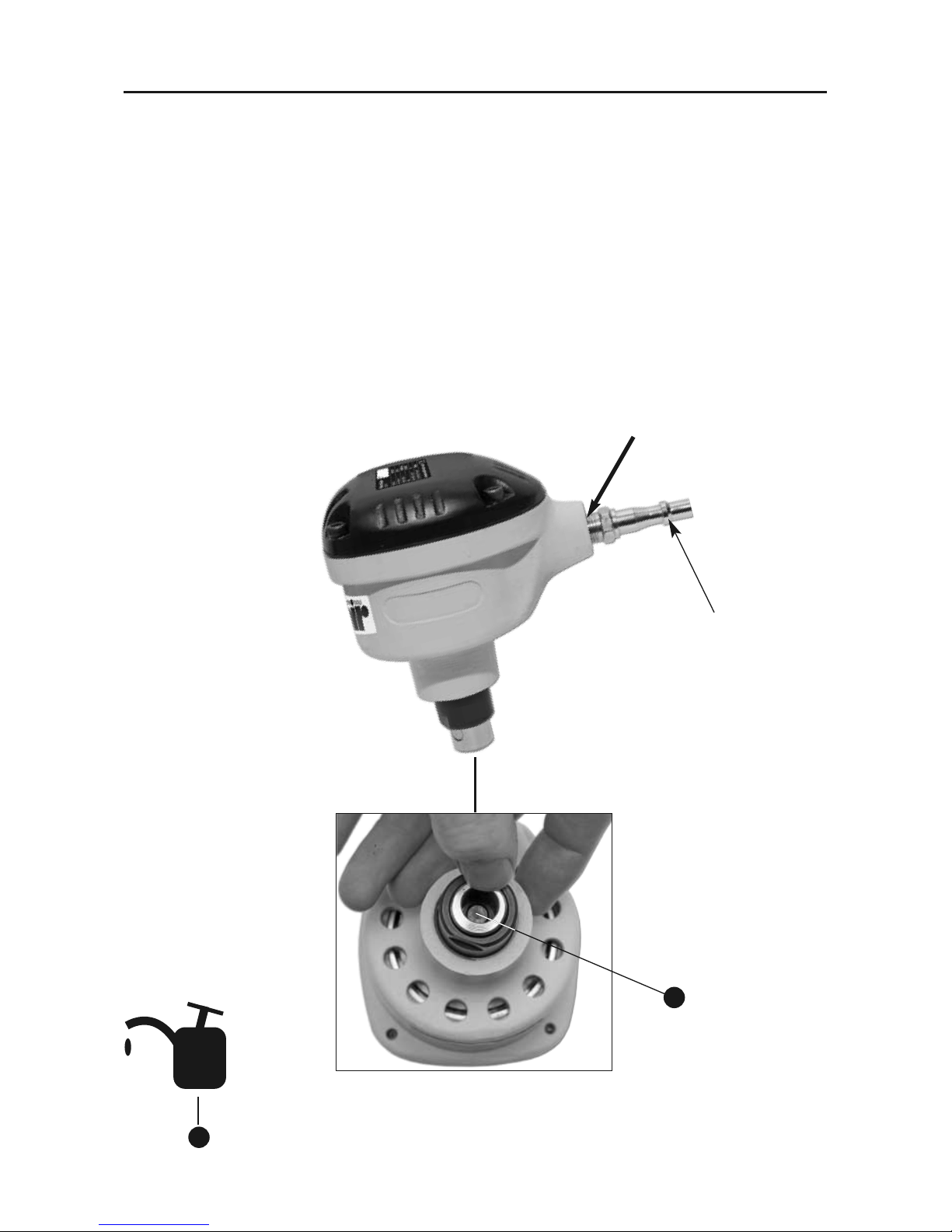
Using the oil supplied in the small oiler bottle, put
2-3 drops into the air connector (See Fig 6 &6a). It is
always a good policy to add at least a drop of oil to
the tool prior to the first use of the day, even if you
have automatic oilers fitted to you supply system. If
you do not have in line oilers, put 2-3 drops of oil
into the tool first thing and then add 2 drops every
1-2 working hours.
Nailer Operation (Simplified)
The nailer is basically a double acting piston, with a
striker connected to it. When air is supplied to the
tool it is so designed as to be stable with the piston/striker in the ‘down’ position; with the porting
directing the air to the top side of the cylinder, all
vents closed. When the piston is pushed up it
changes the porting to vent the air from the top of
the cylinder, close the bottom port and to direct air
into the lower side. This drives the piston up; when
the piston reaches the top of its stroke, it changes
the porting to shut off the top vent, open the lower
vent and direct air into the top of the cylinder, this
drives the piston down, attempting to reach its
stable position. If it is unable to achieve this stable
position, because the nail is holding it off, it repeats
the cycle, and will continue to do so until the nail is
been driven deep enough to no longer exert a
destabilising force on the striker/piston.
Note. Sometimes, perhaps due to the tool being
dropped, the piston is moved to mid strike where is
neither’ twixt nor’ tween, if this happens air will
bleed through both sides of the piston and the
nailer will be unable to cycle. This can usually be
rectified by a sharp ‘slap’ on the head of the nailer
to ‘shake’ the piston one way or the other, this will
enable the nailer to achieve its stable position.
Connect the palm nailer to the hose line, check
there are no leaks anywhere in the system.
Organise a piece of scrap timber and a nail of the
size and type you wish to use. Insert the head of
the nail into the shroud of the nailer against the
striker; it will be held by the small magnetic retainer
in the wall of the shroud. Locate the point of the
nail to the timber and press down firmly.
Try to position the nailer so as to drive the nail
straight. Be prepared for the rapid hammer action,
and the slight ‘drumming’ through the hand. As the
nail is driven deeper into the timber the nailer is
‘held off’ the surface by the action of the sprung
shroud; this is to give greater control over the
depth to which you wish to drive the nail. If you
continue to press down, i.e. fully depressing the
shroud, the nailer will continue to hammer and the
depth to which the nail is driven will depend on
the size of the nail (i.e. the resistance to being
driven into the timber, length, head size, timber
type etc, ) versus the air pressure you have supplied
to the tool. Obviously, the higher the pressure the
more force will be applied to the striker, and the
deeper the nail can be driven.
Establish the best pressure etc., to give the desired
results before commencing the job proper.
Page 13
TroubleShooting
13
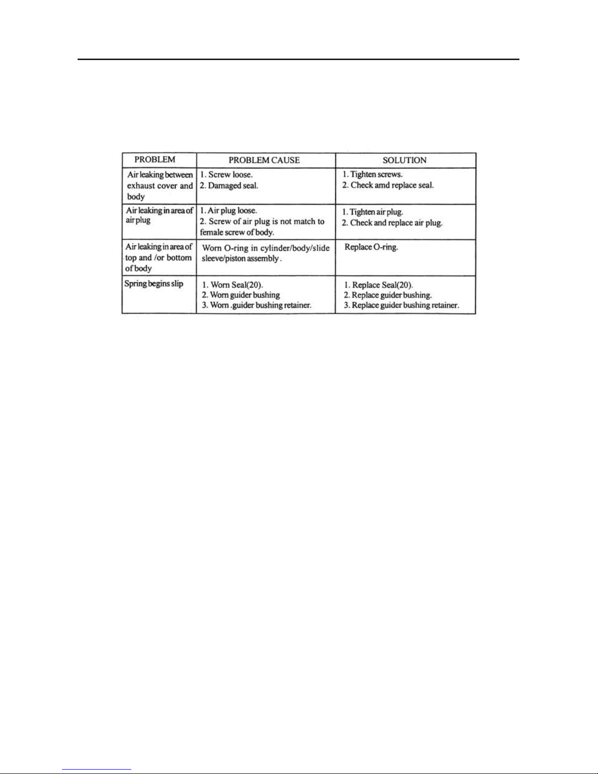
STOP USING THE TOOL IMMEDIATELY IF ANY OF THE FOLLOWING PROBLEMS OCCUR. SERIOUS PERSONAL INJURY COULD OCCUR. ANY REPAIRS OR REPLACEMENTS MUST BE DONE BY A QUALIFIED OR
AN AUTHORISED SERVICE CENTRE ONLY.
Page 14
Maintenance
14
Keep the tool clean, and free from any splashes that may be picked up from current work, e.g. paint, glue,
etc.
Frequent but not excessive oiling is the key to keeping your air tools working properly.
Lack of oil and water will damage your air tools. If your air system is not fitted with water traps and in line
oilers, make sure that the tool is not allowed to ‘dry’ or to retain moisture.
Keep the tool stowed safely away when not in use.
Do not allow sawdust et al., to ingress the tool.
Quick release
connector
Few drops of oil
Fig 6
Fig 6a
OIL
Few drops of oil
(PNEUMATIC OIL ONLY)
Page 15
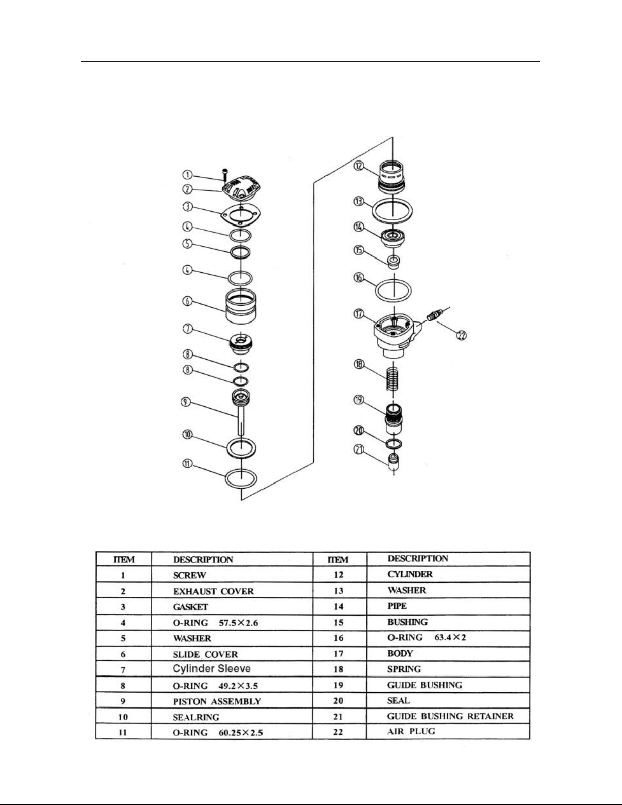
Illustrated Parts List & Breakdown for the Tacker/Pinner
15
Page 16

 Loading...