

Page 1
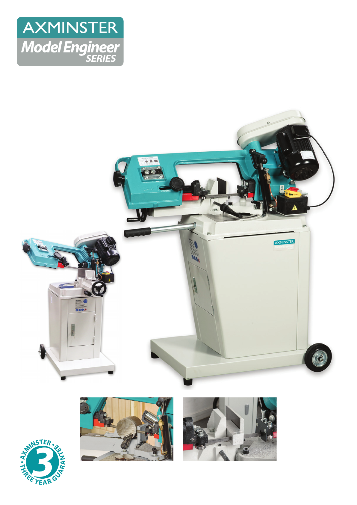
MCB115SHD
Swivel Head Metal
Cutting Bandsaw
Code 700103
Original Instructions
AT: 03/09/2021
BOOK VERSION: 03
Page 2
Cert No: MCB128SHD
EU Declaration of Conformity
Axminster Tool Centre Ltd
Axminster Devon
EX13 5PH UK
axminstertools.com
declares that the machinery described:-
Type
Model
Signed
Andrew Parkhouse
Operations Director
Model Engineer Bandsaw
MCB115SHD
Date: 30/04/2019
This machine complies with the following directives:
2006/42/EC
EN ISO 16093:2017
EN 60204-1:2006+A1+AC
06/42/EC - Annex I/05.2006
conforms to the machinery example for which the
EC Type-Examination Certificate No AM 50435549
has been issued by Laizhou Planet Machinery Co., Ltd.
at: Yutai West Street Laizhou 261400 Shandong China (Mainland)
and complies with the relevant essential health and safety requirements.
Page 3

Page 4
Page 5

Preface
Before commissioning the machine, please read these operating instructions thoroughly
and get familiar with the machine. Please also make sure that all persons operating the
machine have read and understood the operating instructions beforehand.
Keep these operating instructions in a safety place nearby the machine.
Information
The operating instructions include indications for safety-relevant and proper
installation, operation and maintenance of the machine. The continuous observance
of all notes included in this manual guarantee the safety of persons and of the machine.
The manual determines the intended use of the machine and includes all necessary information for
its economic operation as well as its long service life.
The illustration and information included in the present manual can possibly deviate from the current
state of construction of your machine. Being the manufacturer we are continuously seeking for
improvements and renewal of the products. Therefore, changes might be performed without prior
notice. The illustrations of the machine may be different from the illustrations in these instructions with
regard to a few details. However, this does not have any influence on the operability of the machine.
Therefore, no claims may be derived from the indications and descriptions.
Your suggestion with regard to these operating instructions are an important contribution to optimising
our work which we offer to our customers. For any questions or suggestions for improvement, please
do not hesitate to contact our service department.
Warning
Failure to read, understand and follow the instructions in this manual may result in
fire or serious personal injury—including amputation, electrocution, or death.
The owner of this machine/tool is solely responsible for its safe use. This responsibility
includes but is not limited to proper installation in a safe environment, personnel training and
usage authorization, proper inspection and maintenance, manual availability and
comprehension, application of safety devices, cutting/sanding/grinding toolb integrity, and the
usage of personal protective equipment.
The manufacturer will not be held liable for injury or property damage from negligence,
improper training, machine modifications or misuse.
1
Page 6

1. Safety
This operating instructions
▲explains the meaning and use of the warning notes included in these operating
instructions
▲defines the intended use of the metal cutting bandsaw
▲points out the dangers that might arise for you or others if these instructions are not
observed.
▲informs you how to avoid dangers.
In addition to these operation instructions, please observe
▲the applicable laws and regulations
▲the statutory provisions for accident prevention
▲the prohibition, warning and mandatory signs as well as the warning notes on the machine.
If required, the relevant measures to comply with the country-specific regulations must be taken
before commissioning the machine.
Always keep this documentation close to the metal cutting bandsaw.
1.1 Safety instructions for general machinery
The purpose of safety symbols is to attract your attention to possible hazardous conditions. This
manual uses a series of symbols and signal words intended to convey the level of importance of the
safety messages. The progression of symbols is described below. Remember that safety messages
by themselves do not eliminate danger and are not a substitute for proper accident prevention
measures.
WARNING
Some dust created by power sanding, sawing, grinding, drilling, and other construction activities
contains chemicals known to the State of California to cause cancer, birth defects or other
reproductive harm. Some examples of these chemicals are:
• Lead from lead-based paints.
• Crystalline silica from bricks, cement and other masonry products.
• Arsenic and chromium from chemically-treated lumber.
Your risk from these exposures varies, depending on how often you do this type of work. To reduce
your exposure to these chemicals:
Work in a well ventilated area, and work with approved safety equipment, such as those dust
masks that are specially designed to filter out microscopic particles.
2
Page 7
For your own safety, read instruction manual before operating the machine. Learn
the machine’s application and limitations as well as the specific hazards peculiar.
Always wear approved safety glasses or a face shield when operating or observing
machinery to reduce the risk of eye injury or blindness from flying particles Everyday
eyeglasses are not approved safety glasses.
Dust created while using machinery may cause cancer, birth defects, or long-term
respiratory damage. Be aware of dust hazards associated with each workpiece
material, and always wear an approved respirator to reduce your risk.
Always wear hearing protection when operating or observing loud machinery.
Extended exposure to this noise without hearing protection can cause permanent
hearing loss.
Keep hands and clothing away from moving parts. Always tie back or cover long hair.
Wear non-slip footwear to avoid accidental slips which could cause a loss of
workpiece control.
Personal protective equipment
protective suit safety shoes protective gloves protective glasses
Dirty or contaminated personal protective equipment can cause illness. Clean your
personal protective equipment after each use and once a week.
1.2 Intended use
The metal cutting bandsaw is designed and manufactured for use in non-explosive environments.
The metal cutting bandsaw is designed and manufactured to saw cold metal, cast material and
plastics or other material that are not hazardous to health and do not generate dust.
The metal cutting bandsaw must not be used on wood.
The pieces to be cut must be of a shape that will allow them to be securely clamped in the machine
vice and ensure that the piece does not come loose when it is being sawn.
The metal cutting bandsaw must only be installed and operated in dry and ventilated areas.
3
Page 8

1.3 Safety instructions for metal cutting bandsaw
BLADE CONDITION
Do not operate with dull, cracked or badly worn blade.
Inspect blades for cracks and missing teeth before each use.
HAND PLACEMENT
Never position fingers or thumbs in line with the cut.
Hands could be crushed in vise or by falling machine components.
ENTANGLEMENT
HAZARDS
Do not operate this bandsaw without blade guard in place.
Otherwise, loose clothing, jewelry, long hair and work gloves can be
drawn into working parts.
BLADE REPLACEMENT
When replacing blades, make sure teeth face toward the workpiece.
Wear gloves to protect hands and safety glasses to protect eyes
WORKPIECE HANDLING
Always support the workpiece with table, vise, or some type of support
fixture.
Flag long pieces to avoid a tripping hazard. Never hold the workpiece
with your hands during a cut.
LOSS OF STABILITY
Unsupported workpieces may jeopardize machine stability and cause
the machine to tip and fall which could cause serious injury.
POWER INTERRUPTION
Unplug machine after power interruption.
Machines without magnetic switches can start up after power is
restored.
FIRE HAZARD
Don’t use the wrong cutting fluid which will lead to chip fire and possible
explosion.
CUTTING FLUID SAFETY
Always follow manufacturer’s cutting fluid safety instructions.
Pay particular attention to contact, contamination, inhalation, storage
and disposal warnings. Spilled cutting fluid is a slipping hazard.
ATTENTION TO WORK
AREA
Never leave a machine running and unattended.
Pay attention to the actions of others in the area to avoid unintended
accidents.
MAINTENANCE/SERVICE
All inspections, adjustments, and maintenance are to be done with the
machine OFF and the plug pulled from the outlet. Wait for all moving
parts to come to a complete stop.
HEARING PROTECTION
& HAZARDS
Noise generated by blade and workpiece vibration, material handling,
and power transmission can cause permanent hearing loss over time
and interfere with communication and audible signals. Always wear
hearing protection.
HOT SURFACES.
Due to friction, the workpiece, chips, and some machine components
can be hot enough to burn you.
No list of safety guidelines can be complete. Every shop environment is different.
Accidents are frequently caused by lack of familiarity or failure to pay attention. Use this
machine with respect and caution to lessen the possibility of operator injury. If normal
safety precautions are overlooked or ignored, serious personal injury may occur.
4
Page 9

1.4 Safety devices
The metal cutting bandsaw must only be used with fully functional safety devices. Stop the metal
cutting bandsaw immediately if a safety device is defective or becomes ineffective. This is your
responsibility!
If a safety device has been activated or has failed, the machine must only be used if you have
eliminated the cause of the fault and have verified that there is no danger to personnel or objects.
If you bypass, remove or override a safety device in any other way, you are endangering
yourself and other persons working with the machine. The possible consequences are:
▲injuries due to components or parts of components flying off at high speed,
▲contact with rotating and circulating parts
▲and fatal electrocution.
The metal cutting bandsaw features the following safety devices:
▲a protective cover for the V-belts
▲a saw blade casing with protective cover at the rear,
▲protective covers on the saw belt guide.
1.4.1 Saw arch
The saw arch of the metal cutting bandsaw is fitted with a protective cover which is firmly bolted into
place. The protective cover protects the belt guide pulleys and the rotating saw belt.
WARNING! Danger of injury! The teeth of the saw belt are sharp. Take great care when
opening the protective cover to change the saw belt.
Close and mount all protective covers before restarting the metal cutting bandsaw.
1.4.2 Saw blade guide
Refit the protective covers after each saw blade change.
1.4.3 V-belt casing
The V-belt casing is fitted with a protective cover. The protective cover shields the V-belt pulleys.
WARNING! Pull out the mains plug before you open the casing and change the saw belt
speed.
The metal belt saw switches on only when the protective cover is closed. Close all
protective covers before restarting the metal belt saw.
5
Page 10

1.5 Reasonably foreseeable misuse
Any use other than that specified under "Intended use" or any use beyond the described use will be
deemed non-intended use and is not permissible. Any other use must be discussed with
the manufacturer.
In order to avoid misuse, the operating instructions must be read and understood before
first commissioning. The operator of the metal cutting bandsaw must be duly qualified.
1.5.1 Avoiding misuse
▲ Use the correct metal belt saw bands and tooth pitch, depending on the material to be sawn.
▲ Correct belt speed and feed rate of the material to be sawn.
▲ Clamp the workpiece firmly and as free of vibration as possible.
▲ Long workpieces must be supported. Use a suitable support.
1.6 Possible dangers caused by the metal cutting bansdaw
The metal cutting bandsaw has undergone a safety inspection (hazard analysis with risk
assessment). It has been designed and built on the basis of this analysis using state-of-the-art
technology.
Anyway, there is a residual risk as the machine operates under electrical voltage and currents and
saw blade.
We have used design and safety engineering to minimize the health risk to personnel resulting from
these hazards. If the machine is used and maintained by personnel who are not duly qualified, there
may be a risk resulting from incorrect or unsuitable maintenance.
This manual uses a series of symbols and signal words intended to convey the level of
importance of the safety messages.
Remember that safety messages by themselves do not eliminate danger and are not a
substitute for proper accident prevention measures.
1.7 Operator positions
The operator must stand beside the metal cutting bandsaw.
The mains plug of the metal cutting bandsaw must be freely accessible.
1.8 Safety check
Check all safety devices when starting any task, once a week and after any maintenance and repair
work. The metal belt saw switches on only when the protective cover is closed. Close all protective
covers before restarting the metal belt saw.
1.9 Safety during operation
We specifically point out the dangers in the description of work with and on the metal cutting bandsaw.
6
Page 11

CAUTION! Before switching on the metal band saw, ensure that there is no risk of personal injury or
damage to property.
A
void any unsafe work methods:
▲ Make sure that your operation does not create a safety hazard.
▲ The rules specified in these operating instructions must be observed during assembly, operation,
maintenance and repair.
▲ Do not work on the metal belt saw if your concentration is reduced, for example because you are
taking medication.
▲ Observe the accident prevention regulations issued by your Employers Liability Insurance
Association or other supervisory authorities responsible for your company.
▲ Stay with the metal belt saw until all movements have come to a complete standstill.
▲ Use the specified personal protective equipment. Ensure you wear well-fitting clothing and, if
necessary, a hairnet.
1.9.1 Disconnecting and securing the metal cutting bandsaw
Pull out the power plug before beginning any maintenance or repair. All machine parts as well as all
dangerous voltages must be switched off.
Live parts and movements of machine parts can cause severe injury to yourself and
others! Proceed with extreme caution, if the mains plug of the metal belt saw cannot be
disconnected due to the nature of the required work (e.g. functional check).
1.9.2 Using lifting equipment
The use of unstable lifting and load suspension equipment that might break under load
can cause severe injuries or even death. Check that the lifting and load suspension
equipment are of sufficient load-bearing capability and are in perfect condition. Fasten
loads carefully. Never walk under suspended loads!
1.9.3 Mechanical maintenance
Remove or install protective safety devices before starting and after completing any maintenance
tasks, including:
▲ covers ▲ safety instructions and warning signs ▲ grounding cables.
If protection or safety devices are removed, they must be refitted immediately after
completion of the work. Check that they are working properly!
7
Page 12

Page 13

INFORMATION
This numerical value was measured on a new machine under the operating conditions
specified by the manufacturer. The noise behaviour of the machine may change
depending on the age and wear of the machine. Furthermore, the noise emission also
depends on production engineering factors, speed, material and clamping conditions.
INFORMATION
The specified numerical value is the emission level and not necessarily a safe working
level. Although there is a correlation between the degree of noise emission and the
degree of noise disturbance, this cannot be used reliably to determine whether further
precautionary measures are required or not.
The following factors influence the actual degree of noise to which the operator is exposed:
▲ Characteristics of the working area, e.g. size of damping behaviour,
▲ other noise sources, e.g. the number of machines,
▲ other processes taking place in proximity and the period of time, during which the
operator is exposed to the noise.
Furthermore, it is possible that the admissible exposure level may vary from country to country due
to national regulations.
This information about the noise emission should, however, allow the operator of the machine to
more easily evaluate the hazards and risks.
CAUTION!
Depending on the overall noise exposure and the basic threshold values, machine
operators must wear appropriate ear protection. We generally recommend the use of
noise and ear protection.
9
Page 14
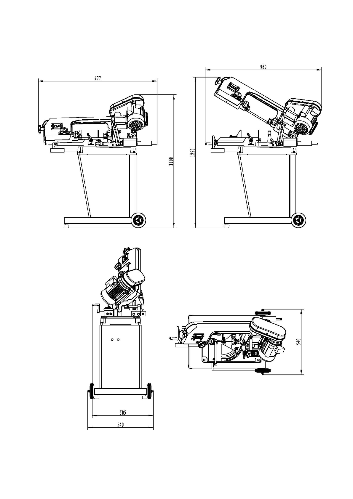
2.6 Dimensions
10
Page 15

Page 16

Page 17

Page 18

Page 19
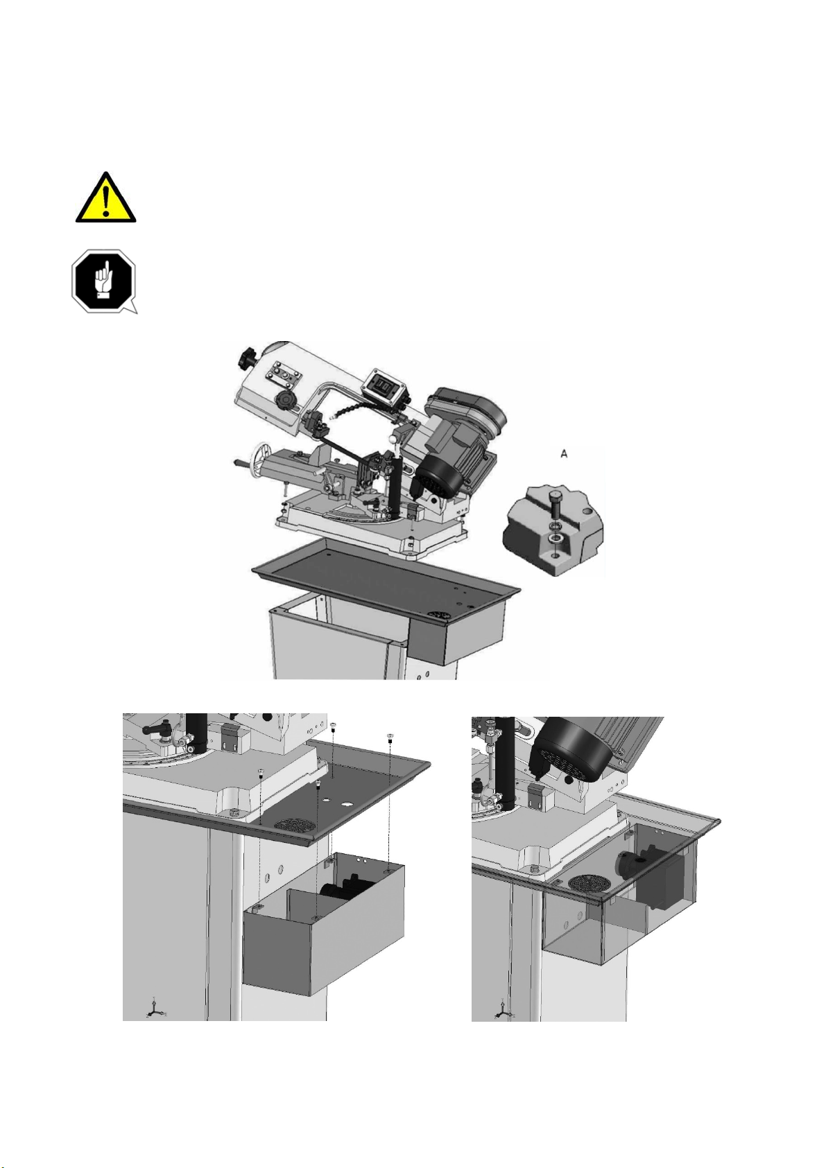
6. Place the oil drip tray, metal bandsaw on the machine substructure and bolt the three parts
together. (FOR MCB128SHD-B ONLY)
DANGER!
Danger of crushing and overturning. The metal belt saw must be fitted to the machine
substructure by at least 2 people. Weight 75 kg excluding the machine substructure.
CAUTION!
The acceptable load for individuals may be exceeded when the metal belt saw is fitted to
the machine substructure. Wear safety shoes.
7. Assemble the cooling pump system on the drip tray. (FOR MCB128SHD-B ONLY)
15
Page 20

Page 21

3.4.2 Position and direction of the saw blade
WARNING!
Danger of injury! The teeth of the saw blade are sharp. Wear protective gloves.
▲Check the position of the saw blade The saw blade must be seated on the shoulders of the saw
blade rollers and be located between the blade guide rollers.
▲Check the direction of the saw teeth. The saw teeth must point in the direction of the drive motor
looking from the operator's position.
▲You will need to remove the rear protective cover on the saw arch to be able to carry out the
checks.
saw blade saw blade roller shoulders
▲Turn the front saw blade rollers several times by hand. To do this, slacken the V-belt and remove
it from the V-belt washers. The saw blade must not move.
▲If the saw blade moves on the saw blade rollers or rubs too heavily on the shoulders of any of the
saw blade rollers, the position of the front saw belt roller must be altered.
3.4.3 Altering the position of the saw blade roller
D
Saw blade
B
A
Shaft fixing bolt
Adjusting screw
C
17
Page 22

Page 23

Page 24

Page 25

Page 26

Page 27
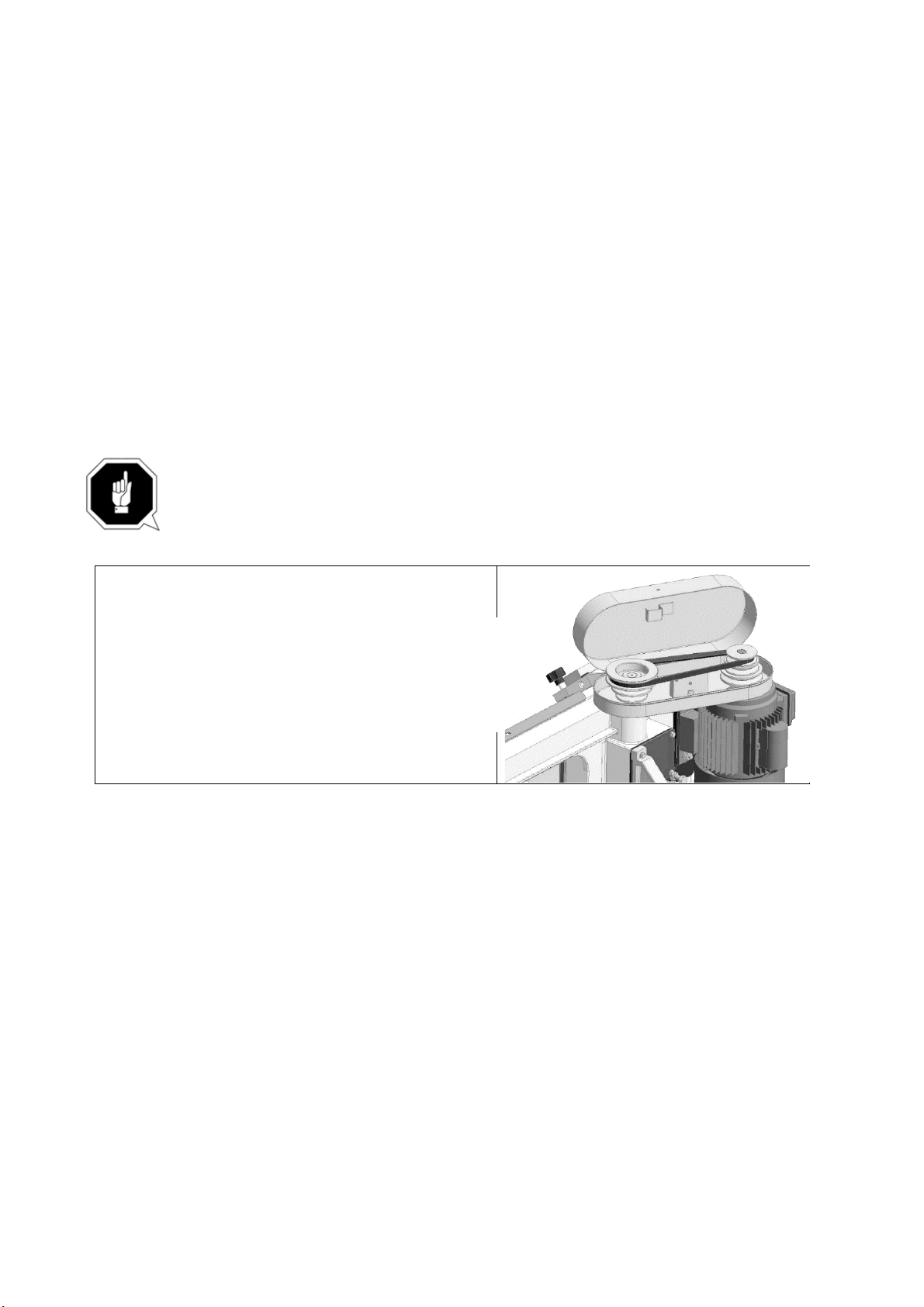
4.8 Setting the saw blade speed
WARNING!
Pull out the mains plug before you open the protective cover. Close and screw down the
protective cover after each change of speed.
▲ Disconnect the metal bandsaw from the power supply.
▲ Slacken the V-belt with the tensioning screw and Allen screw on the motor.
▲ Place the V-belt in the required position on the pulleys.
▲ Tighten the V-belt with the tensioning screw and Allen screw on the motor.
▲ Check the V-belt tension.
▲ Close and bolt down the protective cover.
INFORMATION
It is impossible to start the machine when the protective cover is not closed.
ATTENTION!
Ensure that the V-belt is tensioned correctly. Too high or too low tension of the V-belt can
cause damage.
23
Page 28

4.9 Blade Selection
The chart below is a basic starting point for choosing blade type based on teeth per inch (TPI) for
variable tooth pitch blades and for standard raker type bimetal blades/HSS blades. However, for
exact specifications of bandsaw blades, contact the blade manufacturer.
Here are some general rules of thumb with respect to bandsaw blade use.
▲ At least three teeth must contact the metal at any phase of the cut. Otherwise, the teeth can
load up with metal, fracture, and break off. If the TPI is too high, the teeth can load up with material
and overheat, damaging the blade.
▲ For a faster but rougher cut, use a blade with a lower TPI and a higher feed rate.
▲ For a slower but smoother cut, use a blade with more TPI and a lower feed rate.
To select the correct blade TPI:
1. Measure the material thickness. This measurement is the length of cut taken from
where the tooth enters the workpiece, sweeps through, and exits the workpiece.
2. Refer to the "Material Thickness" row of the blade selection chart in Figure 21, and
read across to find the workpiece thickness you need to cut.
3. Refer to the "Shape" of metal and "Material Type" columns, and find the shape and material to be
cut.
4. In the applicable row, read across to the right and find the box where the row and column
intersect. Listed in the box is the minimum TPI recommended for the variable tooth pitch blades,
and the TPI for bimetal raker blades in parentheses.
24
Page 29

4.10 Feed rate
The speed at which the saw blade will cut through a workpiece is controlled by blade type and feed
rate.
The feed rate is controlled by the valve lever and feed rate dial on the hydraulic cylinder.
Turning the valve lever in-line with the piping opens it up, which allows the fluid to circulate and
allows the head to move.Turning the valve lever sideways or perpendicular to the pipiing closes it,
which locks the headstock in place. The feed rate dial controls the amount of fluid that circulates
around the hydraulic cylinder, which in turn, controls the speed that it moves.
To set the feed rate:
1. Raise the headstock and turn the valve lever
sideways (horizontally).
2. Clamp the workpiece in the table vise.
3. Move the headstock and blade a few inches
above the workpiece.
4. With the correct saw blade installed and
blade speed selected, turn the saw ON.
5. Slowly rotate the feed rate dial to a
conservative feed rate until the saw begins to
cut the workpiece.
6. Observe the chips that exit the cut, and
increase or decrease the feed rate according to
the chip characteristics.
25
Page 30
5. Maintenance
This chapter contains important information about
▲ Inspection
▲ Maintenance
The diagram below shows you which tasks fall under these categories.
ATTENTION!
Properly performed regular maintenance is an essential prerequisite for operational
safety, failure-free operation, a long service life of the metal belt saw and the quality of
the products which you manufacture. Installations and equipment from other manufacturers must
also be in good condition.
ENVIRONMENTAL PROTECTION
Make sure that coolant, lubricants and oils are not spilt on the floor.
Clean up any spilt liquid or oils immediately using proper oil-absorption methods and dispose of
them in accordance with current environmental protection regulations.
Collecting leakages
Do not re-introduce liquids spilt outside the system during repair or as a result of
leakage into the reserve tank; collect them in a collecting container for disposal.
Disposal
Never dump oil or other environmentally hazardous substances which are harmful to
the environment in water inlets, rivers or canals. Waste oils must be taken to a
collection point. Please consult your supervisor for further information on your nearest
collection point.
5.1 Schedule
For optimum performance from your machine, follow this maintenance schedule and refer to any
specific instructions given in this section.
Daily Check Monthly Check Annual Check
• Loose mounting bolts.
• Damaged saw blade.
• Worn or damaged wires.
• Any other unsafe condition.
• Clean after each use.
• Proper blade tension.
• Lubricate vise screw.
• Check V-Belt for wear.
26
• Inspect gear lubrication
Page 31

Page 32
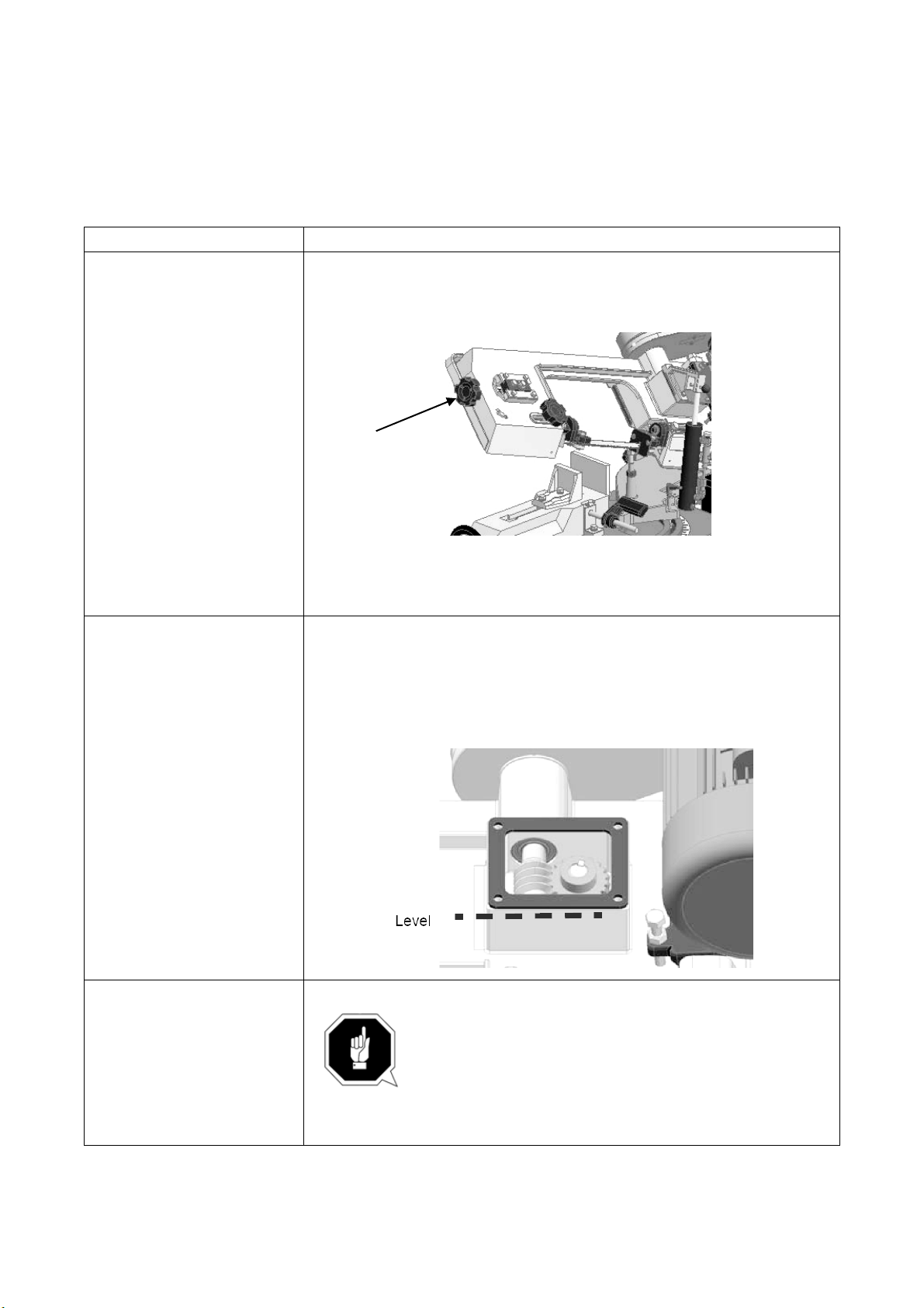
5.4 Inspection and maintenance
The type and level of wear depends to a large extent on specific usage and operating conditions.
Any indicated intervals are therefore only valid for the relevant approved conditions.
What? How?
Setting the saw blade
tension
Checking and top up the
oil in the gear box
Turn the handwheel clockwise to increase the saw blade tension.
The correct saw blade tension is achieved, when you can move the saw
blade with a force of about 50 N in the centre by 3mm.
Hand wheel
Do not tension the saw blade beyond the specified limits.
The saw belt could be overstretched and become warped.
▲ Lower the saw arch completely
▲ Disconnect the lowering cylinder from its mountingon the top.
▲ Remove the top mounting.
▲ Unscrew the gearbox cover.
If necessary, top up with Mobilgear 629 (ISO VG 150) or a comparable oil.
Replacing the blade guide
bearings
ATTENTION!
Always replace the belt guide bearings in pairs.
28
Page 33
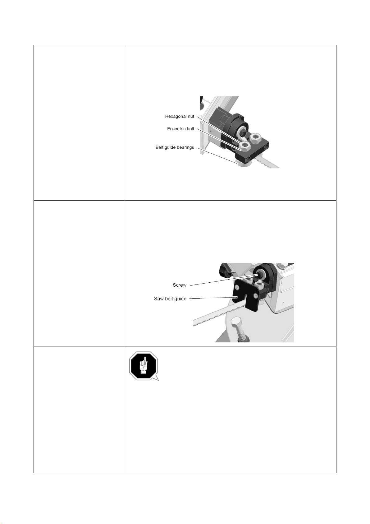
Adjusting the blade guide
bearings
Adjusting the saw blade
guide with respect to the
work table
▲ Place the saw arch in the uppermost position and check that it is safe.
▲ Loosen the hexagonal nut.
▲ Adjust the blade guide bearings with the eccentric bolt, so that the
saw blade can no longer be moved back and forth, but the blade guide
bearings can still be turned by hand.
INFORMATION
Only the belt guide bearings on the operator side have an
eccentric bolt with which you can perform the setting
▲ Place a 90° angular measure in the machine vice and compare the
position.
▲ Using the angular measure, check whether the saw belt is parallel to
the angle.
▲ Loosen the screws on the saw belt guide if the angle is incorrect and
adjust the saw belt guide accordingly.
Changing the saw blade ATTENTION!
The metal belt saw is designed for saw belts with
dimensions 1640 x 13 x 0.6 mm. The use of other saw
belts may result in inferior cutting results.
▲ Place the saw arch in the uppermost position andcheck that it is safe.
▲ Remove the protective covers on the saw blade guide.
▲ Remove the protective cover from the saw arch.
▲ Loosen the tension of the saw blade by turning the hand wheel anti-
clockwise.
▲ Carefully remove the old saw blade.
▲ Fit the new saw blade by inserting it first into the saw blade guide.
▲ Check the running direction and toothing.
▲ Place the saw blade on the two saw blade rollers so that it is as close
29
Page 34

Page 35

6. Malfunctions
6.1 Motor& Electrical
Symptom Possible Cause Possible Solution
Machine does not
start or a breaker
trips.
Machine stalls or is
underpowered.
Machine has
vibration or noisy
operation.
1. Plug/receptacle is at fault or wired
incorrectly.
2. Start capacitor is at fault.
3. Wall fuse/circuit breaker is
blown/tripped.
4. Motor connection wired incorrectly.
5. Power supply is at fault/switched OFF.
6. Motor ON/OFF switch is at fault.
7. Wiring is open/has high resistance.
8. Motor is at fault.
1. Wrong blade for the workpiece
material.
2. Wrong workpiece material.
3. Feed rate/cutting speed too fast for
task.
4. Blade is slipping on wheels.
5. Low power supply voltage.
6. Motor bearings are at fault.
7. Plug/receptacle is at fault.
8. Motor connection is wired incorrectly.
9. Motor has overheated.
10. Motor is at fault.
1. Motor fan is rubbing on fan cover.
2. Blade is at fault.
3. Gearbox is at fault.
4. Wrong blade & too slow of speed.10.
Motor is at fault.
1. Test for good contacts; correct the wiring.
2. Test/replace if faulty.
3. Ensure correct size for machine load; replace weak
breaker.
4. Correct motor wiring connections.
5. Ensure hot lines have correct voltage on all legs and
main power supply is switched ON.
6. Replace faulty ON/OFF switch.
7. Check for broken wires or disconnected/ corroded
connections, and repair/replace as necessary.
8. Test/repair/replace.
1. Use blade with correct properties for your type of
cutting.
2. Use metal with correct properties for your type of
cutting.
3. Decrease feed rate/cutting speed.
4. Adjust blade tracking and tension.
5. Ensure hot lines have correct voltage on all legs.
6. Test by rotating shaft; rotational grinding/loose shaft
requires bearing replacement.
7. Test for good contacts; correct the wiring.
8. Correct motor wiring connections.
9. Clean off motor, let cool, and reduce workload.
10. Test/repair/replace.
1. Replace dented fan cover; replace loose/ damaged
fan.
2. Replace/resharpen blade.
3. Rebuild gearbox for bad gear(s)/bearing(s).
4. Change blade and or speed.shaft requires bearing
replacement.
7. Test for good contacts; correct the wiring.
8. Correct motor wiring connections.
9. Clean off motor, let cool, and reduce workload.
10. Test/repair/replace.
31
Page 36

6.2 Bandsaw operations
Symptom Possible Cause Possible Solution
Machine is
loud when
cutting or
bogs down
in the cut.
Blades
break often.
Blade dulls
prematurely.
Blade wears
on one side.
Teeth are
ripping from
the blade.
The cuts are
crooked.
1. Excessive feed rate.
2. The blade TPI is too great, or the material is too
coarse.
1. Blade is not tensioned correctly.
2. The workpiece is loose in the vise.
3. The feed or cut speed is wrong.
4. The blade TPI is too great, or the material is too
coarse.
5. The blade is rubbing on the wheel flange.
6. The bandsaw is being started with the blade
resting on the workpiece.
7. The guide bearings are misaligned, or the blade
is rubbing on the wheel flange.
8. The blade is too thick, or the blades are of low
quality.
1. The cutting speed is too fast.
2. The blade TPI is too coarse.
3. The blade feed pressure is too light.
4. The workpiece has hard spots, welds, or scale is
on the material.
5. The blade is twisted.
6. The blade is slipping on the wheels.
1. The blade guides are worn or misadjusted.
2. The blade guide slide bracket is loose.
3. The wheels are out of alignment.
1. The feed pressure is too heavy and the blade
speed is too slow; or the blade TPI is too coarse for
the workpiece.
2. The workpiece is vibrating in the vise.
3. The blade gullets are loading up
with chips
1. The feed pressure is too high.
2. The guide bearings are out of adjustment, or too
far away from the workpiece.
3. The blade tension is low.
4. The blade is dull.
5. The blade speed is wrong.
1. Refer to Feed Rate or Changing Blade Speed and
adjust as required.
2. Refer to Blade Selection and adjust as required.
1. Check to see that blade is not excessively tight or
too loose.
2. Clamp the workpiece tighter, or use a jig to hold the
workpiece.
3. Refer to Feed Rate or Changing Blade Speed
and adjust as required.
4. Refer to Blade Selection and adjust as required.
5. Start bandsaw and then slowly lower the headstock
by setting the feed rate.
6. Refer to Blade Guides and adjust as required.
8. Use a higher quality blade.
1. Refer to Changing Blade Speed and adjust as
required.
2. Refer to Blade Selection and adjust as required.
3. Refer to Feed Rate and adjust as required.
4. Increase the feed pressure, and reduce the cutting
speed.
5. Replace the blade.
6. Refer to Blade Tension and adjust as required.
1. Refer to Blade Guides and replace or adjust.
2. Tighten the blade guide bracket.
1. Refer to Blade Selection and decrease the feed
pressure. Refer to Feed Rate and adjust as required.
2. Re-clamp the workpiece in the vise, and use a jig if
required.
3. Use a coarser-tooth blade.
1. Refer to Feed Rate and adjust as required.
2. Refer to Blade Guides and replace or adjust.
3. Refer to Changing the Blade and replace the
blade.
4. Refer to Changing Blade Speed and adjust as
required.
32
Page 37
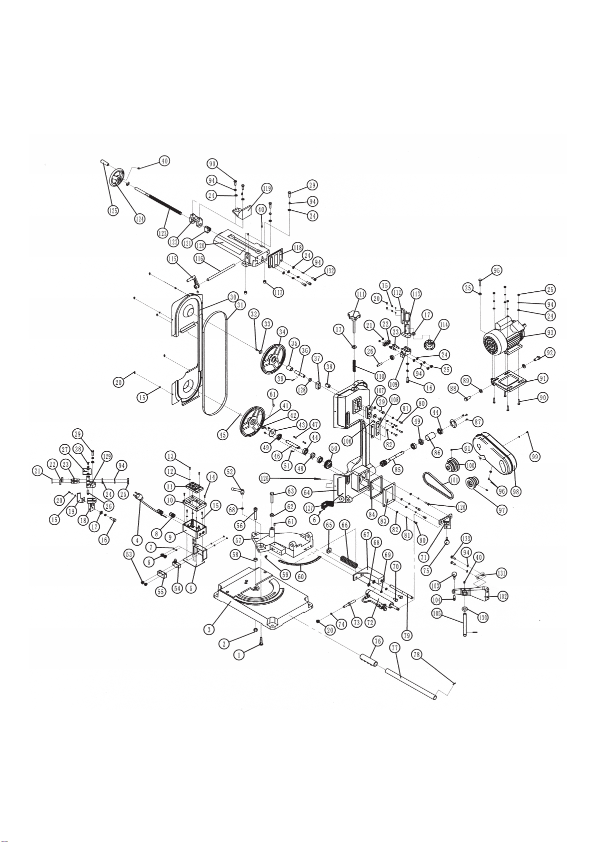
7. Diagram & Part list
7.1 Diagram and part list for MCB128SHD (Part 1)
33
Page 38
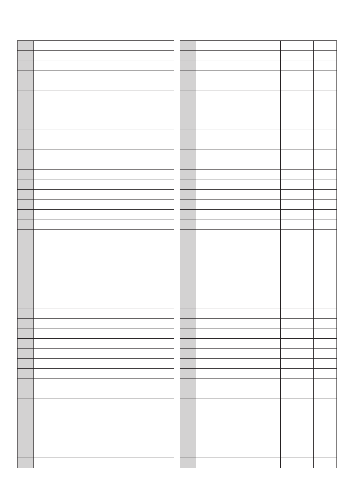
NO. DESCRIPTION SIZE QTY
1 Coach bolt 1
2 Lock nut 1
3 Work table 1
4 Cable and plug 1
5 Switch supporting bracket 1
6 Screw M5 x 10 2
7 Flat washer Φ5 3
8 Cable strain relievers M16 2
9 Lower switch box housing 1
10 Switch plate 1
11 Magnetic switch 1
12 Flat washer Φ4 18
13 screw 2
14 screw 4
15 Flat washer Φ4
16 Hex bolt M10 x 30 1
17 Flat washer Φ10 4
18 Lower adjustment guide 1
19 Lower guard cover 1
20 Screw M4 x 10 3
21 Retaining ring Φ9 4
22 Ball bearing 629ZZ 6
23 Eccentric shaft 4
24 Elastic washer Φ8 16
25 Nut (M8) M8 5
26 Pin 2
27 Blade guide plate 1
28 Screw M6 x 12 2
29 Bolt M8 x 30 7
30 Wheel cover 1
31 Saw blade 1
32 Bolt M5*16 1
33 Droven wheel retaining ring Φ5 1
34 Driven wheel 1
35 Driven wheel position sleeve 1
36 Driven wheel shaft 1
37 Adjustment block 1
38 Elevating block 1
39 Elastic pin M3 x 20 1
40 Screw M6 x 12 6
41 Drive wheel 1
42 Drive wheel position sleeve 1
43 Drive wheel flange 2
44 Ball bearing 4
45 Retaining ring Φ15 1
46 Drive wheel shaft 1
47 Spuare key C5*20 2
48 Worm shaft sleeve 1
49 Sealing gasket 15*35*7 2
50 Worm 1
51 Screw M4 x 24 2
52 lock level M10 1
53 Cylinder spring M4 x 30 2
54 Lock knob LXW5-11 1
55 Switch box 1
56 Screw M12 x 65 1
57 Angle adjustment base 1
58 Position sleeve 1
59 Angle pointer 1
60 Angle scale label 1
61 Screw(M6X16) M6 x 16 1
62 Nut M12 1
63 Bolt M12 x 60 1
64 Saw bed 1
65 Square nut 1
66 Spring 1
67 Spring holder 1
68 Flat washer Φ10 4
69 Elastic washer Φ10 4
70 Bolt (M 10x20) M10 x 18 2
71 Hydraulic cylinder holder 1
72 Hydraulic cylinder 1
73 Connecting rod 1
74 Big flat washer Φ4 1
75 Valve knob 1
76 Plastic sleeve 1
77 Bar 1
78 Pin M2.5 x 40 1
79 Adjustment rod 1
80 Bolt M6 x 15 6
81 Elastic washer Φ6 12
82 Flat washer Φ6 13
83 Gear box cover 1
84 Sealing gasket 1
85 Worm shaft 1
34
Page 39

86 Worm shaft sleeve 1
87 Screw M4 x 10 6
88 Bolt M12 x 30 1
89 Flat washer Φ12 2
90 Plastic cable fixing plate M8 x 25 8
91 Motor base 1
92 Bolt 1
93 Motor 550W 1
94 Flat washer Φ8 13
95 Bolt M8 x 40 1
96 Knob M6 x 30 1
97 Motor pulley 1
98 Pulley cover 1
99 Bolt M4 x 10 2
100 Gear box pulley 1
101 V-Belt O-500 1
102 Connecting block 1
103 Position knob 1
104 Position pin 1
105 Turning shaft 1
106 Screw M8 x 20 1
107 Sliding block 1
108 Pressing plate 2
109 Upper guard holder 1
110 Spring 1
111 Blade tebsion knob 1
112 Upper guard cover 1
113 Adjusting holder 1
114 Lock knob 1
115 Stock stop 1
116 Stock stop rod 1
117 Vise position sleeve 2
118 Rear vise jaw 1
119 Front vise jaw 1
120 Vise bed 1
121 Threaded rod nut 1
122 Front jaw holder 1
123 Threaded rod 1
124 Hand wheel 1
125 Turning handle 1
126 Bolt M6 x 30 1
127 Stop block 1
128 Position sleeve 1
129 Adjusting holder 1
130 Flat washer Φ16 1
131 Flat plate 1
132 Bolt M8 x 20 3
133 Bolt M8 x 30 2
35
Page 40
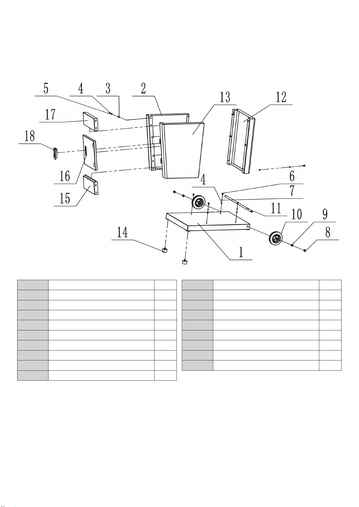
7. 3 Diagram and part list of cabinet for MCB128SHD
Cabinet Stand
NO. DESCRIPTION QTY
1 Base plate 1
2 Left plate 1
3 Coach bolt 14
4 Flat wahser 18
5 Nut 14
6 Bolt 4
7 Elastic washer 4
8 Lock nut 2
9 Flat washer 2
10 Wheel 2
11 Wheel shaft 1
12 Rear plate 1
13 Right plate 1
14 Feet 2
15 Front lower plate 1
16 Door 1
17 Front upper plate 1
18 Lock 1
36
Page 41
Page 42

The Axminster guarantee
Buy with confidence from Axminster!
So sure are we of the quality, we cover all parts and labour free of charge for three years!
For more information visit axminstertools.com/3years
The packaging is suitable for recycling.
Please dispose of it in a responsible manner.
EU Countries Only
Do not dispose of electric tools together with household waste material.
By law they must be collected and recycled separately.
Axminster Tools, Axminster Devon EX13 5PH
axminstertools.com
 Loading...