

Page 1
1998
700124
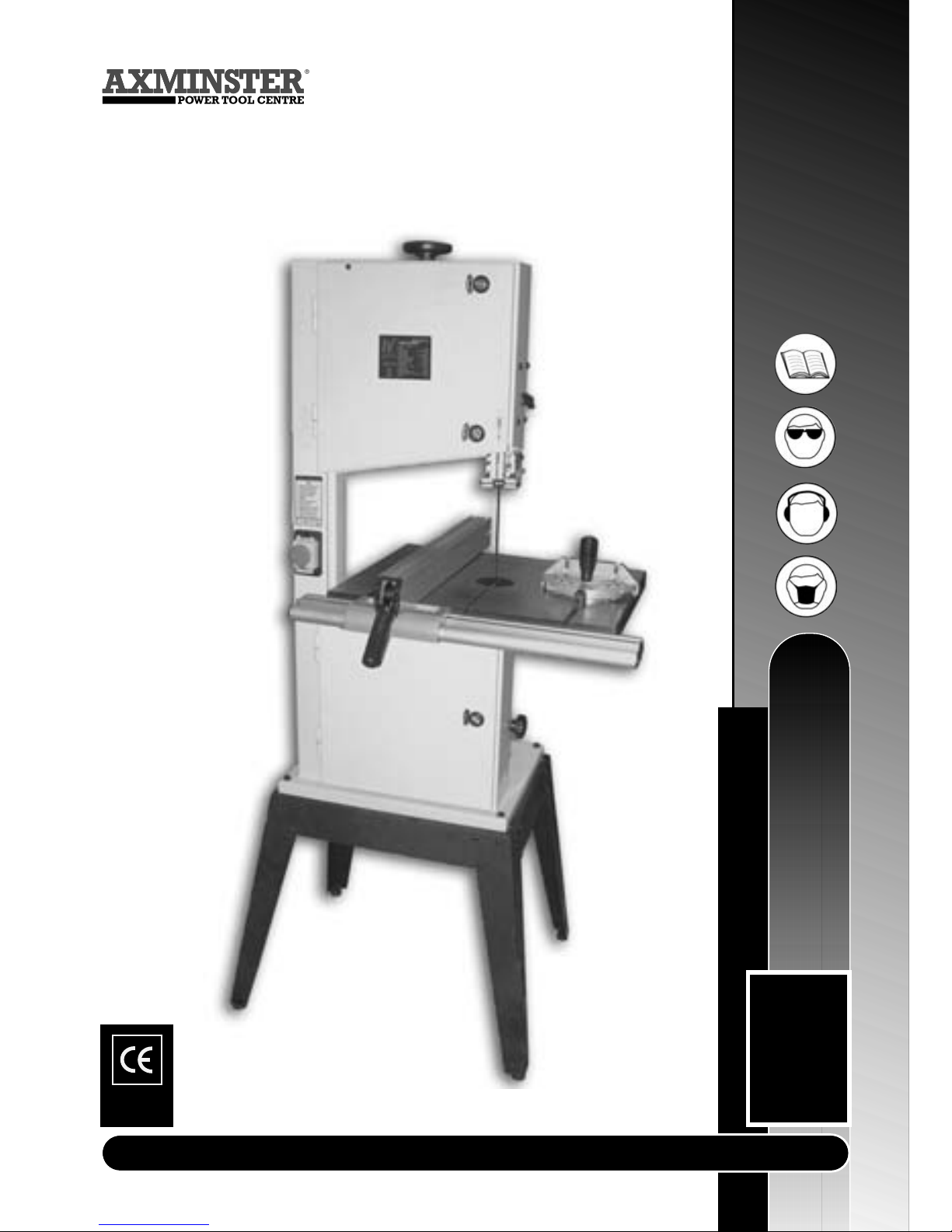
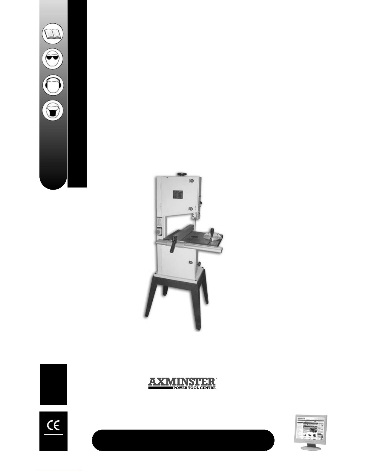
AWBB Bandsaw
Axminster Reference No:AWBB
User Manual
WHITE
AXMINSTER
W
www.axminster.co.uk
Page 2
Index of Contents...
Page No.
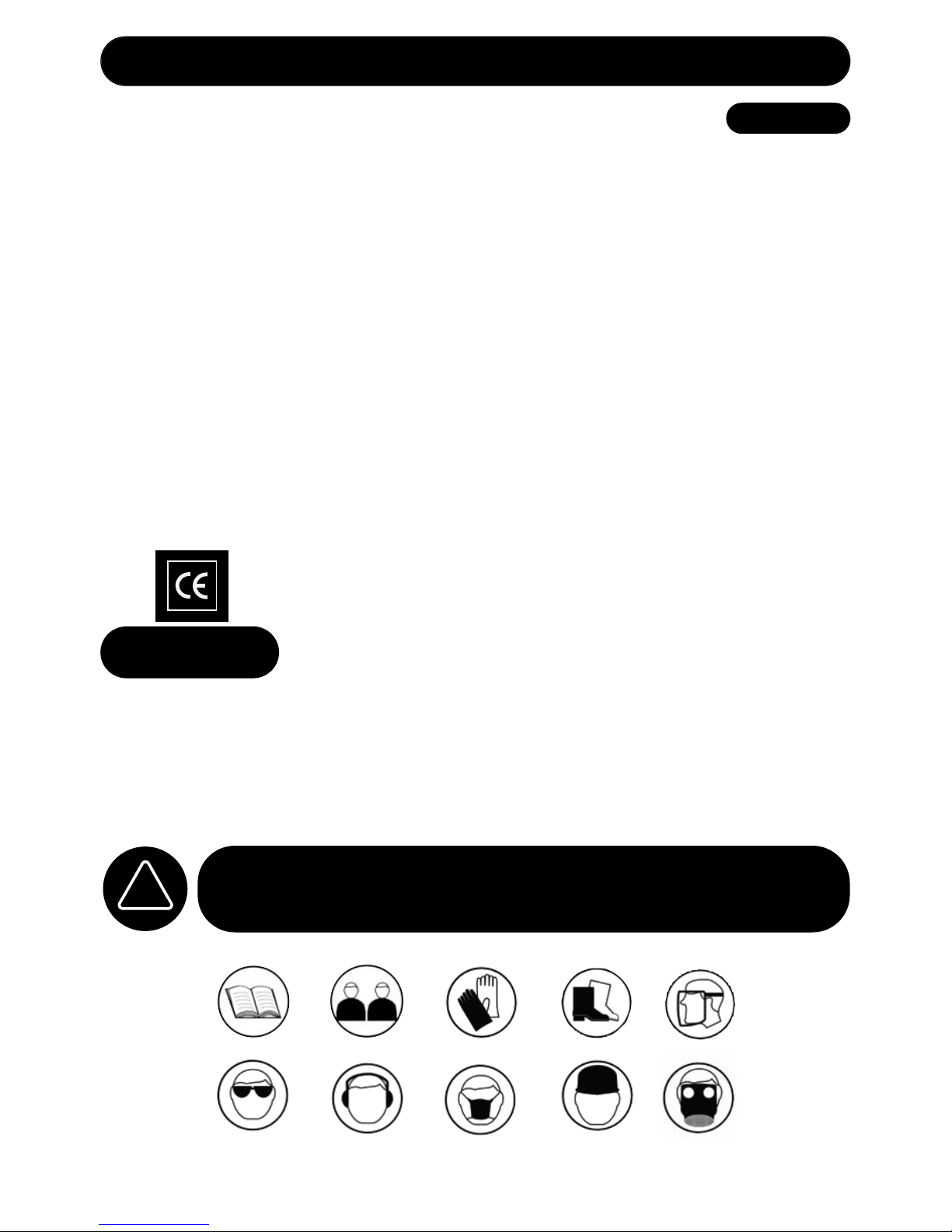
Safety Protection Symbols
SAFETY!!
!
The symbols shown on the cover of this
manual advise that you wear the correct
safety protection when using this machine.
E
y
e
P
r
o
t
e
c
t
i
o
n
S
a
f
e
t
y
H
e
l
m
e
t
P
r
o
t
e
c
t
i
v
e
G
l
o
v
e
s
S
a
f
e
t
y
F
o
o
t
w
e
a
r
R
e
s
p
i
r
a
t
o
r
S
a
f
e
t
y
V
i
s
o
r
R
e
a
d
M
a
n
u
a
l
T
w
o
M
a
n
A
s
s
e
m
b
l
y
E
a
r
D
e
f
e
n
d
e
r
s
D
u
s
t
M
a
s
k
The undersigned, K. Ehret authorised
by Shandong Laizhou Industrial Sewing Machine Factory No: 275 Wen Quan East
Road, Laizhou, Shandong 261400 P.R. China
declares that this product:
Wood Cutting BandSaw
MJ343B,MJ343C
( Serial no: FL23150919,FL23150919)
manufactured by Shandong Laizhou Industrial Sewing Machine Factory is in
compliance with the following standards or standardisation documents
EN 55 014:1993, EN 61000-3-2:1995
EN 61000-3-3:1995, EN 55 014-2:1997
in accordance with Council Directives, 98/37/EC
Copied from
CE Certificate
Index of Contents............................................................................................................................................ 2
Declaration of Conformity....………………………………………………...........................................................2
What’s in the Box.....................................…………......................................................................................... 3
General Instructions for 240v Machines
.....................……………………………………………............ 3-4
Initial
Assembly................….…….......……………………………........…………....…................................ 5-6-7
Specification...................................................................................................................................8
Identification and Parts Description....………….………………............................................................ 8-10-16
Illustration and Parts Description..................................................................…......................... 9-11-17-18-19
Parts Breakdown.....................................………...................................................................................... 12-13
Parts List 1 & 2......................................................................................................................................... 14-15
Setting up the Saw..................................................……….......................................................................20-21
Operating Instructions.....................................
……………………....................................................22-23
Changing the Saw Blade........................…………………………………….................................................... 23
Page 3
WHITE
AXMINSTER
W
03
What’s in the Box...
Having unpacked your accessories(see overleaf) please dispose of any unwanted packaging
properly. The cardboard packaging is biodegradable.
Please read the Instruction Manual prior to using your new machine; as well as
the operating procedures for your new machine, there are numerous hints and tips to
help you to use the machine safely and to maintain its efficiency and prolong its life.
Keep this Instruction Manual readily accessible for any others who may also be required
to use the machine.
Good Working Practices/ Safety
The following suggestions will enable you to observe good working practices, keep yourself and
fellow workers safe and maintain your tools and equipment in good working order.
WARNING!! KEEP TOOLS AND EQUIPMENT OUT OF THE REACH OF
YOUNG CHILDREN
Mains Powered Tools
Primary Precautions
These tools are supplied with a moulded 13 Amp. plug and 3 core power cable. Before
using the tool inspect the cable and the plug to make sure that neither are damaged. If
any damage is visible have the tool inspected/repaired by a suitably qualified person.
!
Model Number: MT343B
1 No. Bandsaw
1 No. Bandsaw blade
2240mm long 4 TPI Skip assembled in the Saw...(not tensioned)
1 No. Saw table
1 No. Fence Guide
1 No. Mitre Guide
1 No. Packet containing the On/Off Switch Safety Shroud
1 No. Table Insert
1 No. Floor Stand Kit comprising:-
4 No. Legs
4 No. X-Ties (2 long, 2 short)
1 No. Packet containing
4 No. M8*40mm Hexhead Bolts, Nuts and Washers
(to secure bandsaw to stand)
24 No. M8*15mm Roundhead bolts, Nuts & Washers
(to assemble floor stand)
1 No. Instruction Manual
1 No. Guarantee Card
!
General Instructions for 240v Machines...
Page 4
04
WHITE
AXMINSTER
W
General Instructions for 240v Machines...
Mains Powered Tools
Primary Precautions (Continued)
If it is necessary to replace the plug, it is preferable to use an ‘unbreakable’ type that will
resist damage on site. Only use a 13 Amp plug, and make sure the cable clamp is tightened
securely. Fuse as required. If extension leads are to be used, carry out the same safety
checks on them, and ensure that they are correctly rated to safely supply the current that is
required for your machine.
Work Place/Environment
Make sure when the machine is placed that it sits firmly on the floor, that it does not rock, that it is
sufficiently clear of adjacent obstacles so that cutting operations will not be impeded. Check you have
adequate clearance both in front of, and behind the machine when cutting long stuff. If you are liable
to be processing unwieldy or awkward work pieces, it is suggested that you consider fastening the
machine down to the floor.
The machine is not designed for sub-aqua operation, do not use when or where it is liable to get wet.
If the machine is set up in the open, and it starts to rain (unusual though this would be in U.K.), cover
it up or move it into the dry. If machine has got wet; dry it off as soon as possible, with a cloth or
paper towel. Do not use 230Va.c. powered machines anywhere within a site area that is flooded or
puddled, and do not trail extension cables across wet areas. Keep the machines clean; it will enable
you to more easily see any damage that may have occurred. Clean the machine with a damp soapy
cloth if needs be, do not use any solvents or cleaners, as these may cause damage to any plastic
parts or to the electrical components.
Keep the work area as uncluttered as is practical, this includes personnel as well as material.
(Under no circumstances should CHILDREN be allowed in work areas).
It is good practice to leave the machine unplugged until work is about to commence, also make sure
to unplug the machine when it is not in use, or unattended. Always disconnect by pulling on the plug
body and not the cable. Once you are ready to commence work, remove all tools used in the setting
operations (if any) and place safely out of the way. Re-connect the machine.
Carry out a final “tightness” check e.g. guide fence, table tilt, etc.., check that the ‘cutting path’ (in this
case; the path that the work piece will travel) is unobstructed.
Make sure you are comfortable before you start work, balanced, not reaching etc..
If the work you are carrying out is liable to generate flying grit, dust or chips, wear the appropriate
safety clothing, goggles, gloves, masks etc., and if the work operation appears to be excessively
noisy, wear ear-defenders. If you wear your hair in a long style, wearing a cap, safety helmet, hairnet,
even a sweatband, will minimise the possibility of your hair being caught up in the rotating parts of the
tool, likewise, consideration should be given to the removal of rings and wristwatches, if these are
liable to be a ‘snag’ hazard. Consideration should also be given to non-slip footwear, etc..
Do not work with cutting tools of any description if you are tired, your attention is wandering
or you are being subjected to distraction. A deep cut, a lost fingertip or worse; is not worth it!
Do not use this machine within the designated safety areas of flammable liquid stores or in
areas where there may be volatile gases. There are very expensive, very specialised
machines for working in these areas, THIS IS NOT ONE OF THEM.
Check that blades are the correct type and size, are undamaged and are kept clean and sharp, this
will maintain their operating performance and lessen the loading on the machine.
Above all, OBSERVE…. make sure you know what is happening around you, and USE YOUR
COMMON SENSE.
!
Page 5
WHITE
AXMINSTER
W
05
Initial Assembly...
Your saw is packed in the box partially assembled. Unfortunately this is more of an exercise to ensure that
the components are inserted in the correct positions than a shortening of the build time. e.g. the blade is
fitted, the securing bolt for the tilt mechanism is inserted in the tilt quadrant with the washer and the locking
butterfly nut threaded on to the bolt, etc..
Please make careful note of the positions of the various components if you have cause to
disassemble, whilst putting the machine together. (Now there’s an oxymoron)
Take all the easily removable items out of the box, tip the box up so that the base of the saw is to the
ground, remove all the polystyrene packaging from around the saw (open both sides of the box?) then
“corner walk” the saw out of the box. If this is still awkward, split the top of the box, fold the box material flat
on the floor, and “wriggle” the saw off the cardboard. (The best method of moving the saw is with a ‘hug’ lift
through the neck of the saw, holding the saw back against your body and lifting by straightening your legs).
Assemble the floor stand as follows:-
Remove the pre-assembled M8x15 bolts, nuts and washers from the packet, remove the nuts and the
washers, separate into different piles, put close to hand. Match the long and the short X-ties of the stand
and select either pair. Take one of the legs and bolt one of the X-ties to it, (the X-ties go on the inside of the
leg ), insert a bolt from the outside of the leg, through the X-tie, fit the washer and the nut, (at this stage do
not tighten any of the nuts and bolts),bolt another leg to the other end of the X-tie following the same
procedure. Fit the other X-tie with the other two legs, and then join these two assemblies together using the
other paired X-ties. When all is assembled, ensure the floor stand is on a flat surface and tighten up all the
nuts and bolts. (You will need a 13mm spanner and a large X-point screwdriver). Assemble the 4 rubber pad
feet to the bottoms of the legs.
Assemble the Table
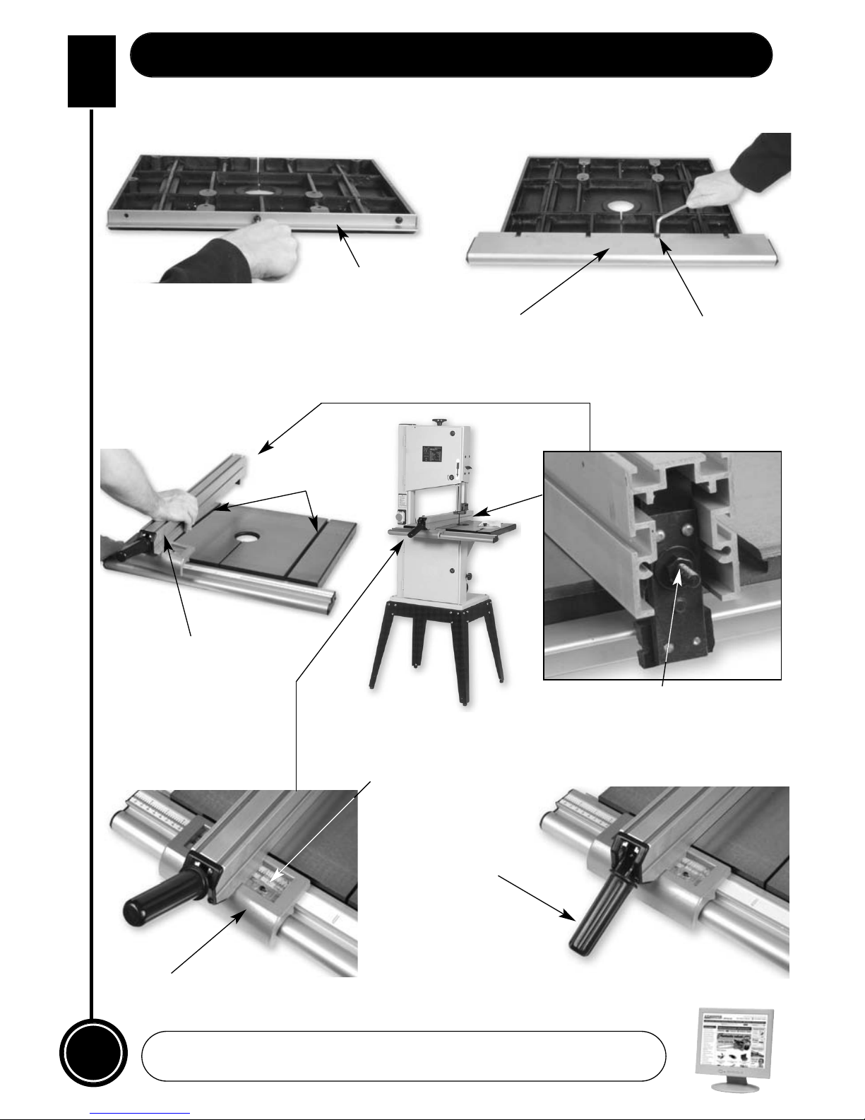
Assemble the back rail to the rear of the table by inserting the M6 bolts and washers, through the predrilled
holes in the extrusion. Because of the off-centre hole the back rail cannot be fitted the ‘wrong’ way.
(See fig 1)
Using the four hex bolts and washers supplied to mount the fence rail by sliding the tongue under the edge
of the table with the cut-outs about the bolts, above the washers. Introduce until fence rail body is against
the edge of the table. (See fig 1a) Tighten the 4 bolts securely.
(DO NOT OVERTIGHTEN, remember this is a casting, over-tightening could cause the threads to
strip).
Fit the guide fence by clipping the rear clamp over the back rail first and dropping the front clamp over the
fence rail. (See fig 2a) Push down on the lock lever, and ensure the fence clamps up correctly. (See fig 2d) If
not, adjust the clamping system by tightening or loosening the nut on the end of the torsion rod at the rear
end of the guide fence blade. (See fig 2b)
Check the guide fence is set parallel to the blade. Any slight discrepancy can be taken out by loosening the
4 No. caphead bolts that secure the blade of the guide fence to the clamping body, adjust and re-tighten.
Larger discrepancies may require that the fence rail is angled slightly.
The dimensioning scales have adjustable index plates set in the fence guide front clamp body to enable the
scales to be zero read. (See fig 2c)
Page 6
06
WHITE
AXMINSTER
W
Initial Assembly (Continued)...
www.axminster.co.uk
Fig 1
Fig 1a
Fig 2
Fig 2a Fig 2b
Fig 2c
Fig 2d
Back rail
Fence rail
‘T’ slots
Typ. 4 Hex bolts
Guide fence
Torsion rod
Lock lever
Guide fence
clamp body
Dimensioning scale
Page 7
Assembling the Saw
Lift the saw on to the completed floor stand, and secure using the 4 No. M8x40 bolts. ( Insert the bolts
through the base of the saw, through the floor stand and fit the washers and nuts on the underside).
The saw table can be fitted without removing the blade, however, if you would feel more comfortable
not having to manoeuvre the table around the blade (the table is quite heavy), remove the blade by
opening the top and bottom covers, release the tension on the blade by backing off the tensioning
wheel (See fig 3), and remove the blade, taking care as it is manoeuvred clear of the guides and the
safety guards.
Preparing the saw table for fitting:-
1.Remove the guide fence rail by loosening the 4 No. bolts holding it to the front of the table. Remove
the table insert.
2. Put a small pencil ‘X’ on the front of the tilt quadrant body. (It will save you working out which way
round it fits). Turn the table upside down, locate the 4 No. bolts securing the tilt quadrant to the table,
loosen and remove them and their washers, (you will need an 11mm spanner). Lift the tilt quadrant
away from the table. Note. There are normally spacing washers fitted between the table and the feet
of the tilt quadrant. Don’t loose them.
3. The securing bolt for the tilt mechanism (an M8x50 coach bolt) is pre-fitted into the tilt quadrant.
Remove the butterfly nut and the washer and fit the tilt quadrant into the tilt housing. Ensure that the
bolt is correctly inserted through the slot and that the little rib cast on the tilt housing corresponds to
the groove in the tilt quadrant. Check that the square under the bolt head is correctly located in its
recess in the casting and refit the washer and the butterfly nut. Before tightening, check that the tilt
mechanism functions correctly. If it doesn’t, something is probably slightly mis-aligned, slacken off the
butterfly nut, re-position the quadrant and try again. When everything is satisfactory, set the tilt
quadrant so that the mounting feet are horizontal and tighten.
4. Place the 4 spacing washers over the holes in the tilt quadrant feet and lift the table into position.
Insert the washered bolts through the feet, the spacing washers, and screw into the table. (As you
insert each bolt and establish a turn or turn and a half into the table I would suggest you leave the
bolts as slack as possible to enable you to manoeuvre the table around to achieve the fitting of the
other bolts). Make sure that you don’t displace the spacing washers during this manoeuvring. When
all the bolts are inserted, tighten firmly. DO NOT OVER -TIGHTEN. Remember this is a casting, if you
drastically over-tighten you could strip the threads.
5. Replace the blade, slipping it through the slot in the table, through the guards and the guides and
over the wheels; apply some tension to the blade to hold it in place. Replace the guide fence rail.
6. If you wish to be able to isolate the saw physically, to prevent unauthorised or unsupervised usage,
a switch shroud is provided. The shroud and the integral dust cover are fitted over the On/Off switch
and secured with two small screws through holes in the outer bezel of the switch plate. It is
suggested that you mount the shroud so that the cover hinge is at the top, i.e. the cover pivots
upward. Although when the hinge becomes more flexible, this sometimes requires the cover to be
lifted out of the way to operate the ON button; in an emergency, a quick slap of the hand will close the
cover and switch the machine Off. With the cover closed a small padlock can be fitted to prevent the
cover being lifted and access to the ON button is denied.
WHITE
AXMINSTER
W
07
Initial Assembly (Continued)
Page 8
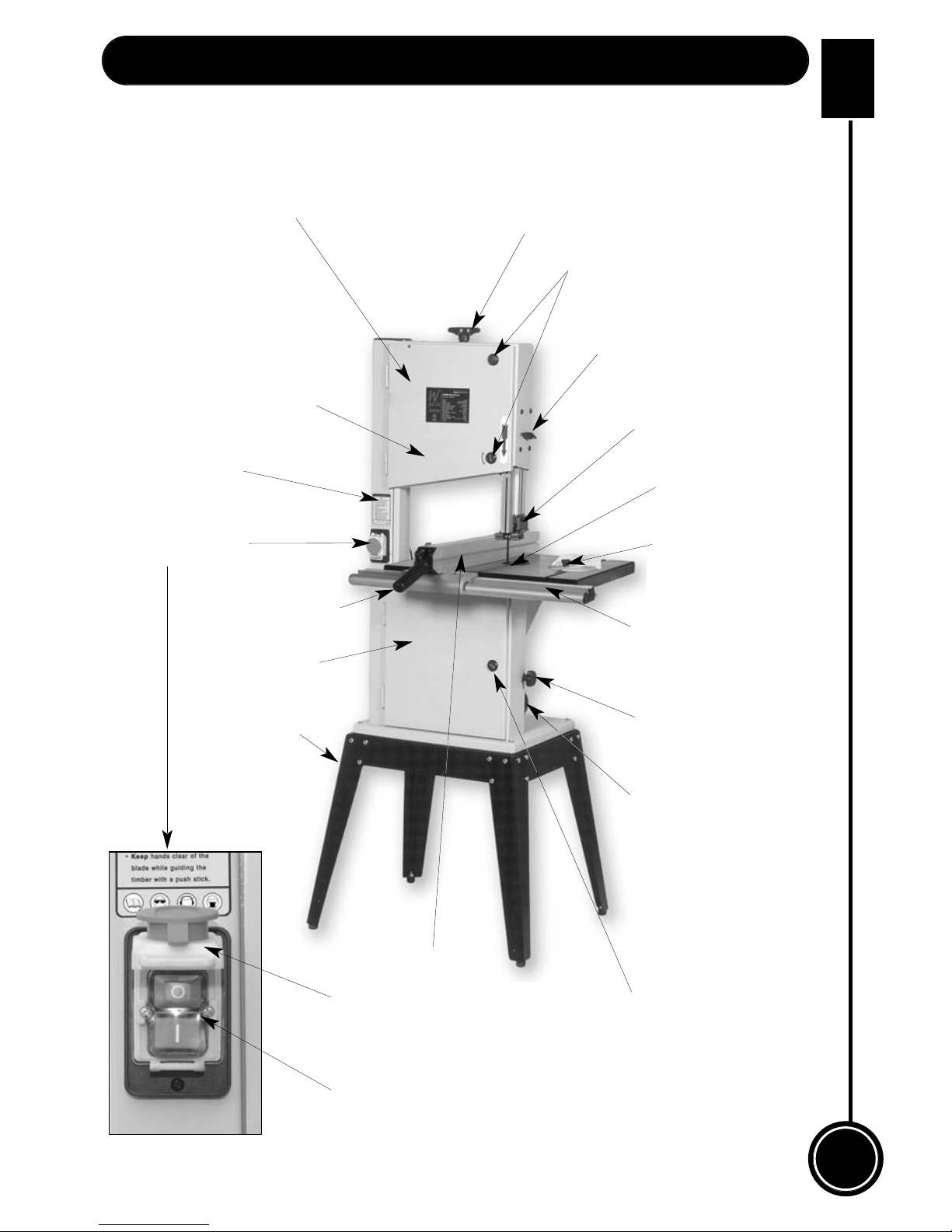
Main saw frame The main body of the machine that all the other parts are mounted upon.
(See fig 3)
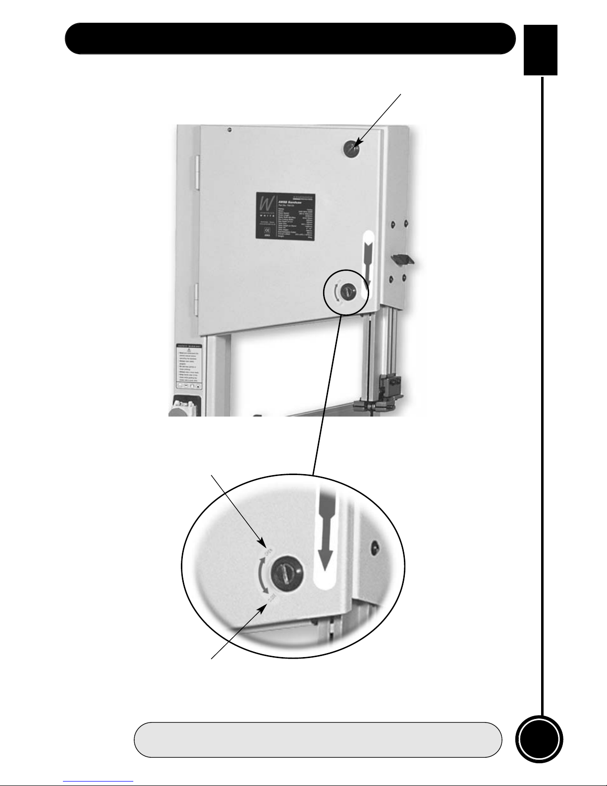
Upper and lower The two doors that cover the upper and lower saw wheel compartments.
cover doors There are interlocks fitted to both doors so that the machine cannot operate
(See fig 3) if either door is left open.
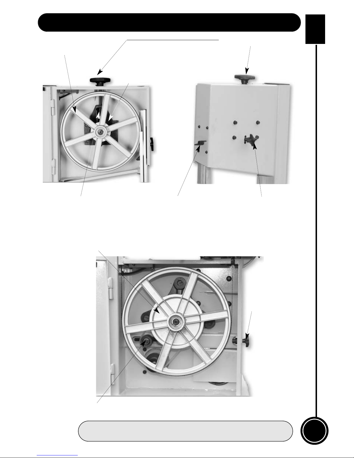
Upper saw The upper saw wheel is mounted on double bearings on an axle that is
wheel mounted to a tilting plate. (To provide the fore and aft tilt movement that
(See fig 4) controls the blade tracking). The tilting plate is hinged to a base plate that is
mounted in slides in the upper saw wheel compartment. (The base plate
slides up and down allowing increasing or decreasing of the blade tension).
The saw wheel is fitted with a rubber tyre to give better grip to the saw blade,
and smoother running. It also allows the blade to be tracked in the centre of
the wheel; unlike the bad old days when the blade had to be tracked off the
front edge of the wheel to safeguard the teeth.
Blade tensioning The blade tensioning wheel, at the top of the machine, is connected
wheel to a threaded rod that is engaged in the base plate of the upper saw wheel
(See fig 4a) axle assembly. The threaded rod is anchored in the top of the saw frame
which allows the base frame to be driven up and down in its mounting slides
and tension or de-tension the blade.
Upper blade The upper blade guide assembly mounts the two side bearings and the rear
guide and thrust bearing that keep the blade stable (straight and untwisted) above the
guard table during the sawing operation. The guard is an integral part of the guide
(See fig 3) mounting leg to which the guide assembly is bolted so it is always in place
when the guide is raised or lowered to its working position.
08
WHITE
AXMINSTER
W
Specification...
Axminster No. 700124 (AWBB)
Motor Input 240V a.c, 50Hz, 1448 rpm, 750W
Motor Output: 550W
Wheel Diameter: 315mm
Blade Speeds: (Off Load) 360 & 720 m/min
Blade Length: 2240mm
Max Depth of Cut:(Throat) (Upright) 160mm
Max Max Cutting Width: (Table Flat) 300mm
Blade Width Min/Max: 6mm (1/4") 16mm 5/8"
Table Tilt: 0-45˚ degrees
Dust Extraction Outlet: 96mm
Overall Size L x W x H: 710mm x 675mm x 1075mm
Supplied Cable Length 2 Metres
Weight 80 kg
Identification and Parts Description...
Page 9
WHITE
AXMINSTER
W
09
Illustration and Parts Description...
Fig 3
Fig 3a
Main saw frame
Upper blade guard
Fence guide rail
Mitre fence
Table insert
Floor stand
Dust Extraction outlet
On/Off button and
switch shroud
On/Off buttons
switch shroud
Upper saw wheel
(inside cover door see fig 4)
Blade tensioning wheel
Upper cover door
Lower cover door
Lower cover door
Latch
Saw guard clamp
Upper cover door latches
Idler wheel adjusting
knob
Lock lever
Guide fence
Page 10
10
WHITE
AXMINSTER
W
Identification and Parts Description...
Upper blade The upper blade guide height clamp is a butterfly nut and coach bolt
guide height arrangement that clamp through the guide mounting leg and the main saw
clamp frame. So, loose it will allow the mounting guide leg to be moved up and
(See fig 4a) down, tightened it will clamp the leg in position against the frame.
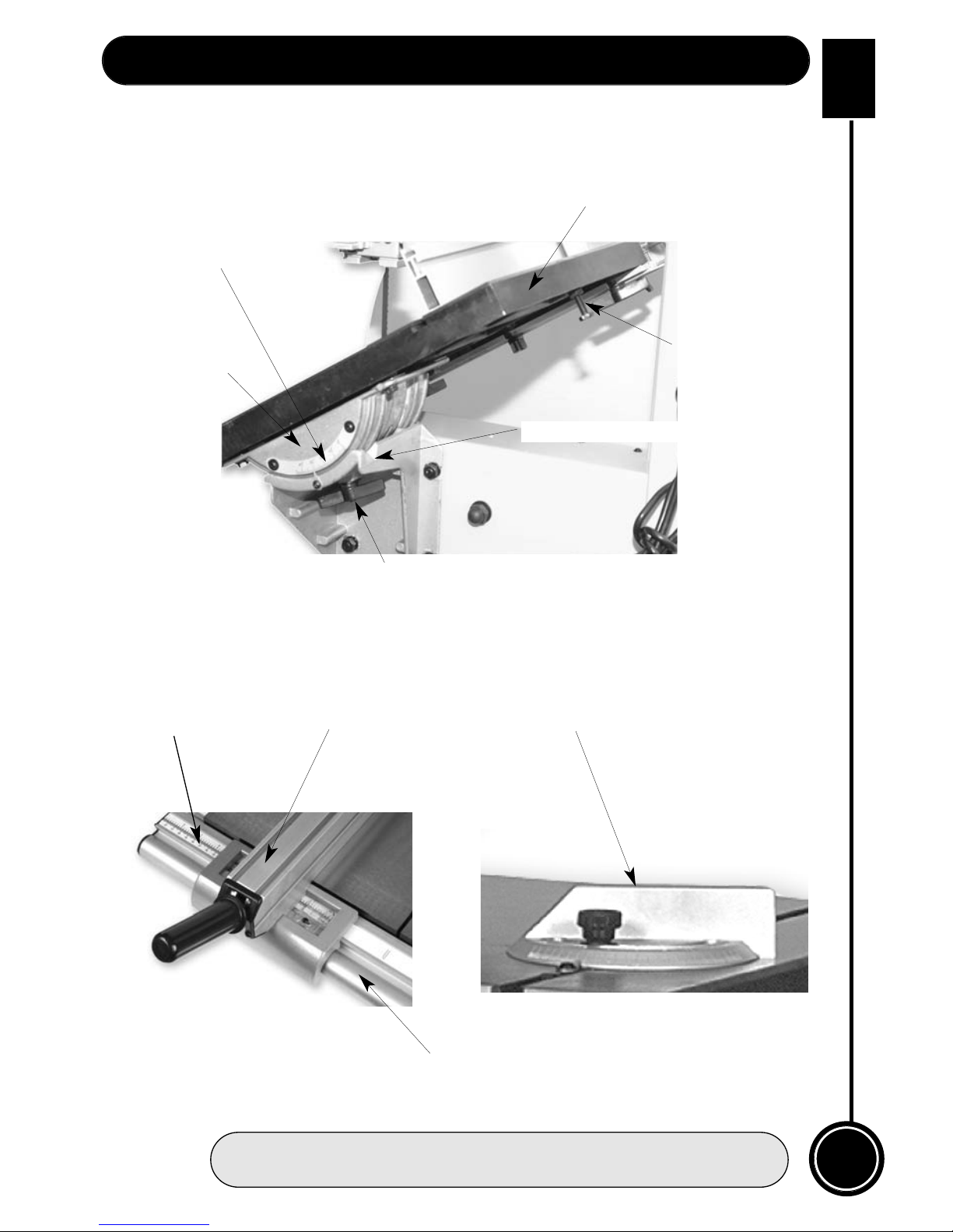
Saw table, tilt The saw table is mounted on the tilt quadrant, which is, in turn mounted in the
assembly quadrant housing and secured via a coach bolt and butterfly nut arrangement.
and scale Loosening the butterfly nut allows the table to be tilted up to 45 degrees
(See fig 6) clockwise. There is an adjustable bolt with a lock nut, screwed into the
underside of the table, which acts as a pre-set stop when bringing the table
back to the level position. There is a scale and pointer attached to the rear of
the quadrant and the housing to measure the angle to which the table has
been tilted. There are two slots machined in the table to accept the slide of
the mitre fence.
Saw table insert The saw table insert fits into the round recessed groove in the centre of the
(See fig 9) table. It not only fills the round void, it also supports the workpiece below the
saw in order to minimise ‘breakout’ from the sawcut. The table insert that is
supplied is for general work, and as such has a fairly wide slot, to allow the
fibre strands from general redwoods and whitewoods to be carried through
by the saw blade. Alternative table inserts should be made when carrying out
very fine work, where the breakout must be kept to a minimum.
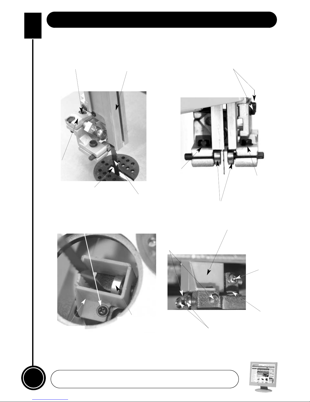
Lower blade The lower blade guide assembly is mounted on the main saw frame below the
guide and table, it mounts the rear thrust bearing and two side guide rods that keep the
guard blade stable (straight and untwisted) below the table during the sawing
(See figs 10 & 11) operation. The lower guard is a red plastic enclosure that screws to the guide
assembly, and shields the blade between the underside of the table and the
top of the lower saw wheel compartment.
Fence guide rail The fence guide rail is a metal extrusion that is bolted onto the saw table with
(See figs 1a & 7) 4 hex bolts and washers. The fixing locations in the guide rail are slots, which
allow the angle of incidence between the table and the guide rail to be
adjusted; to enable the guide fence to be set square to the table. There is a
ruler scale set in the guide rail to aid the setting of the guide fence.
NOTE. The guide fence rail should always be fitted and securely
fastened to the saw table, even if it is not properly set up for the fence.
This is to help maintain the stability of the saw table in the area of the
slot which is cut through the table to allow the blades to be fitted.
Guide fence An extruded aluminium assembly primarily consisting of the main mounting
(See fig 2a) body and the blade. The blade is bolted to the top of the main body. The main
body is shaped to fit over the fence rail and mounts the clamping handle. The
clamping handle is attached to a torsion bar which is fed through the blade of
the guide and acts on the rear clamp, pulling it tight against the back rail
through the lever action of the clamp handle. There is a fixed measurement
scale mounted on the fence rail. On each side of the main body is an aperture
through which this scale can be read. Mounted in each aperture is an
adjustable index, to enable the measurements to be zeroed.
Page 11
WHITE
AXMINSTER
W
11
Illustration and Parts Description...
FREEPHONE 0800 371822
Fig 4
Fig 4a
Fig 5
Tracking control
star knob
Saw guard clamp
Idler Wheel
adjusting knob
Upper saw wheel
Upper wheel mounting
assembly
Threaded rod
Lower saw wheel
Drive belt tensioning idler wheel
Blade tensioning wheel
Page 12
12
WHITE
AXMINSTER
W
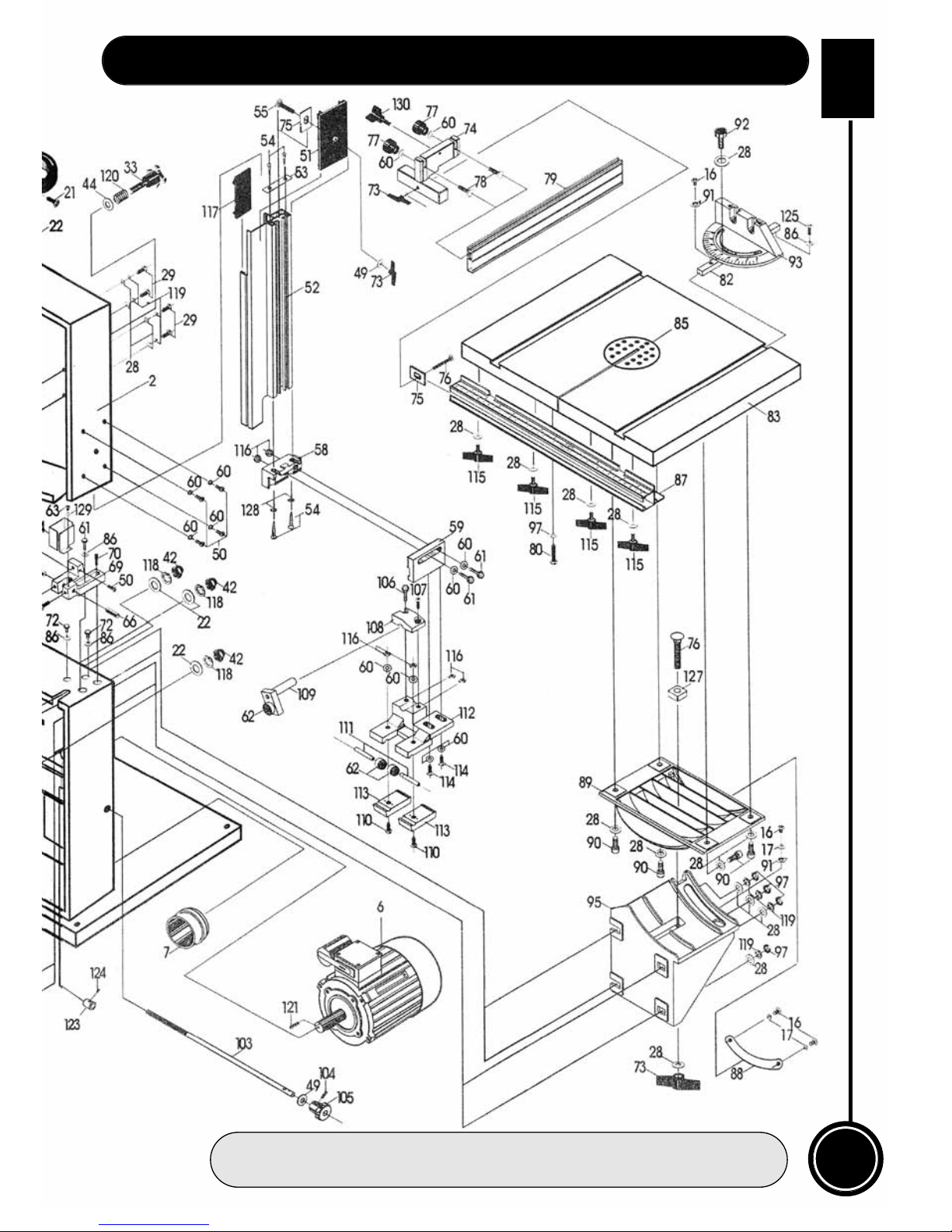
Parts Breakdown...
www.axminster.co.uk
Page 13
WHITE
AXMINSTER
W
13
Parts Breakdown...
FREEPHONE 0800 371822
Page 14
14
WHITE
AXMINSTER
W
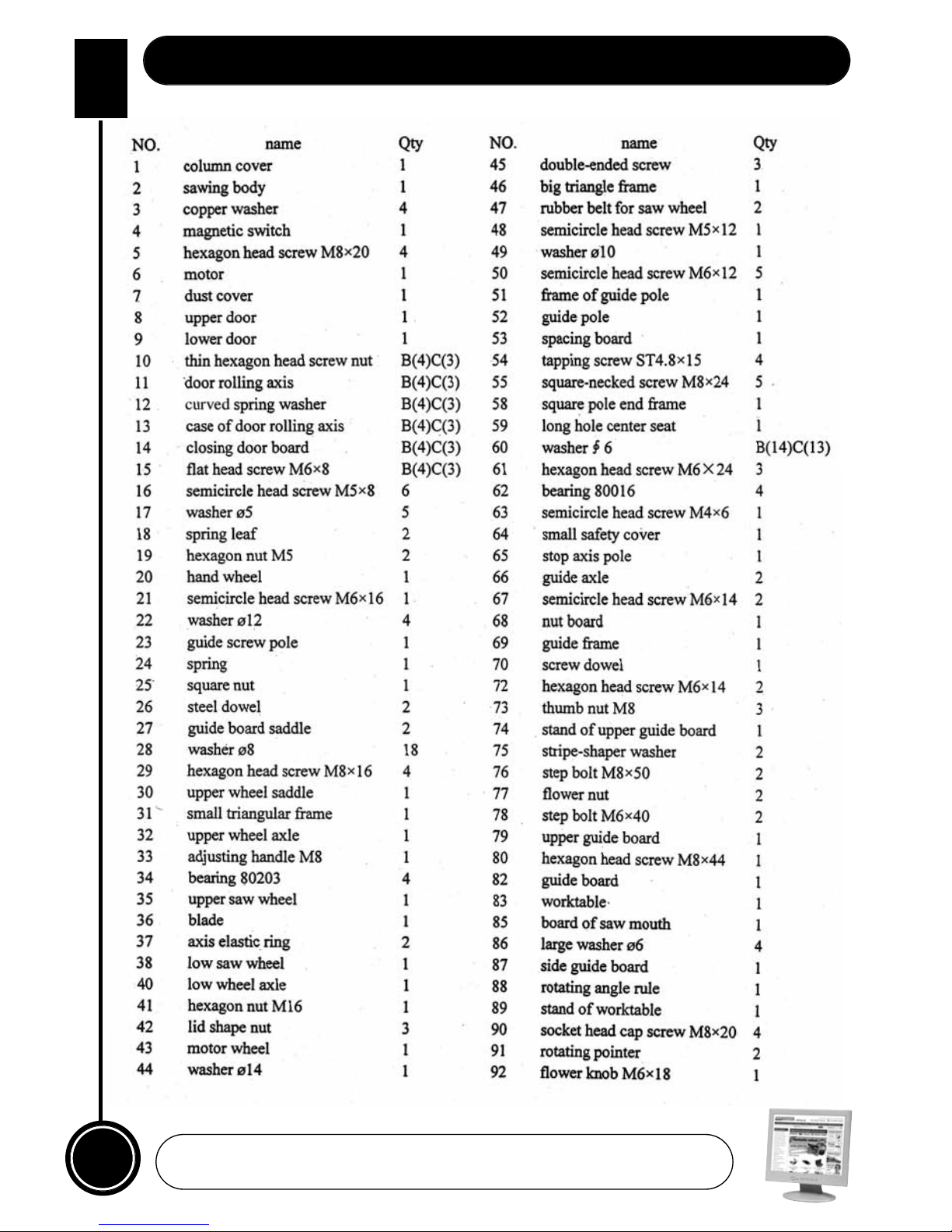
Parts List 1...
www.axminster.co.uk
Page 15
WHITE
AXMINSTER
W
15
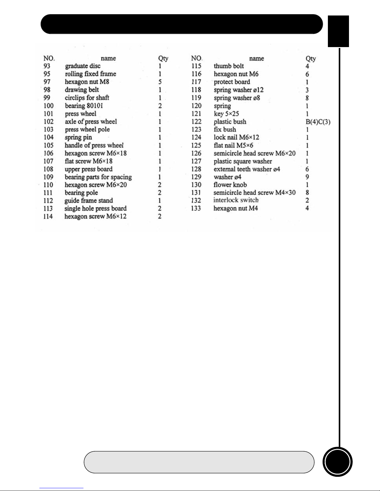
Parts List 2...
FREEPHONE 0800 371822
Page 16
16
WHITE
AXMINSTER
W
Identification and Parts Description...
Mitre fence The mitre fence slide can be engaged in either of the slots in the saw table,
(See fig 8) and acts as an X-feed device, which will enable any angle from 0 to 45
degrees left or right to be cut with the saw.
Back Rail An aluminium extrusion bolted to the rear of the saw table, that is used as
(See fig 1) the rear clamp bracket for the guide fence.
Tracking control The tracking control star knob, at the rear of the top compartment, is
star knob connected to a threaded rod that is engaged in a threaded hole in the base
(See fig 4a) plate of the upper saw wheel axle assembly. The end of the rod pushes
against the lower end of the hinged tilting plate that carries the upper saw
wheel axle. Driving the rod in or out will cause the plate to tilt, and by
association, the upper saw wheel, thus enabling the blade to be ‘tracked’. The
tilting plate is kept in contact with the end of the threaded rod by the tension
on the saw blade, (the downward ‘pull’). It should be self - evident therefore,
that the blade can only be ‘tracked’ whilst it is in tension.
Lower saw The lower saw wheel and integral pulley wheel is likewise mounted on double
wheel bearings, onto an axle that is mounted to a fixed base plate. The base plate,
(See fig 5) triangular in shape, is bolted to the rear face of the lower saw wheel
compartment. There are no adjustment mechanisms for the lower saw wheel.
Mounted on a fixed shaft on a fixed base it is the base parameter that the rest
of the saw is set against.
Drive belt The drive belt tensioning idler wheel (the idler), is mounted on a stub axle
tensioning assembly that is captive in a slotted base plate. The Idler Wheel
idler wheel adjusting knob, on the side of the lower saw wheel compartment, is
(See figs 4 &4a) connected to a threaded rod which is engaged in the stub axle assembly. The
rod is anchored in the side of the main saw frame, so that turning the knob
will drive the stub axle assembly back and forth along the slot in the base
plate. This allows the drive belt to be tensioned, or the tension removed to
allow the belt to be changed or moved to the alternate groove to change the
speed. Remember; the belt is tensioned by ‘pushing’ the idler forward against
the belt, not ‘pulling’ the idler back against the belt.
Dust extraction A 96mm diameter dust extraction outlet.
outlet
(See fig 3)
On/Off Button The On/Off buttons, fitted with the optional shroud, (see the initial assembly
and switch instructions).
shroud
(See fig 3a)
Page 17
WHITE
AXMINSTER
W
17
Illustration and Parts Description...
FREEPHONE 0800 371822
Fig 6
Fig 7
Fig 8
Fence guide rail
Guide fenceRuler scale Mitre Fence
Tilt scale and
pointer
Tilt Quadrant
Saw table
Table preset
level stop
Tilt mechanism clamp
Quadrant housing
Page 18
18
WHITE
AXMINSTER
W
Illustration and Parts Description...
www.axminster.co.uk
Fig 9 Fig 10
Fig 11 Fig 12
Side guides
Saw table
insert
Saw
blade
Saw guardCross point screw
Bolt “B”
Bolt “B”
Bolts “A”
Rear bearing
clamp
Side guide
Plastic safety box
Screw ‘D’
Clamping screws ‘E’
Bolt ‘C’
Rear thrust
bearing
Lower guard
Safety box
Holding screw
Page 19
WHITE
AXMINSTER
W
19
Illustration and Parts Description...
FREEPHONE 0800 371822
Upper cover door latches
Open
Close
Fig 13
Fig 13a
Page 20
20
WHITE
AXMINSTER
W
Setting Up the Saw...
Tensioning and tracking the blade
Make sure both top and bottom blade guides are well clear of the blade.
Open the front covers fully, giving good access to the top compartment of the saw
(see fig 4) and good visibility into the bottom compartment (see fig 5). Check that the blade
is sitting approximately in the middle of the wheels. Apply some tension to the blade by
turning the tensioning wheel clockwise, spin the top wheel and check that the blade
remains centrally on the tyre, if it does not, adjust the tracking by turning the tracking
control at the rear of the head box (see fig 4). (Viewed directly onto the tracking control
wheel, turning clockwise should cause the blade to track to the rear of the tyre,
anti-clockwise to the front, DO NOT make large adjustments). Spin the top wheel again,
check again. Continue until the blade tracks in the centre of the tyres with no appreciable to
and fro movement. Tension the blade fully. (A side ways push of about 7-8 lbs(3+kgs) in the
middle of the blade should allow a
1
/
4
”,(6.5mm) distension). Check the tracking again,
adjust if necessary. Check that the drive belt is tensioned correctly, if it is slack, apply ‘take
up’ pressure to the belt by adjusting the ‘idler’ pulley, using the knob at the side of the
machine.(See fig 5). Connect the power to the machine. Stand clear and start the saw,
check that the saw is running smoothly, (no thumps, bumps, knockings or excessive
vibration) and the blade appears to be tracking correctly (in one place). You can check this
by holding a marker, e.g. a pencil, close to the back of the blade (approach from the back
of the blade only) and check that the gap remains constant. If it doesn’t, adjust the tracking
until it does. (If you adjust the tracking with the saw running, make very small adjustments
and wait for the saw to react before you adjust again, sometimes the reaction is not
instantaneous). Once you are satisfied that the tracking is correct switch the machine off
and allow it to run to a stop.
!
DISCONNECT THE MACHINE FROM THE MAINS SUPPLY
!
DISCONNECT THE MACHINE FROM THE MAINS SUPPLY
Checking the table is square
Loosen the butterfly nut clamping the tilt mechanism, and turn the table hard against its
stop. (This is a bolt with a lock nut screwed into the underside of the table, (see fig 6), the
head of the bolt acts as a stop when it strikes the machine frame). Tighten the butterfly nut.
Make sure the upper blade guide is raised as high as possible. Place a square on the table
and move it up against the blade (behind the teeth). Check that the blade is perpendicular
to the table. If it is not, try resetting the table. If it is still not correct, loosen the locking nut
and adjust the bolt until perpendicularity is achieved, tighten the lock nut and then re-check.
When you are satisfied that the table is set correctly, check that the pointer of the tilt gauge
reads zero, if not, adjust it.
Setting the fence
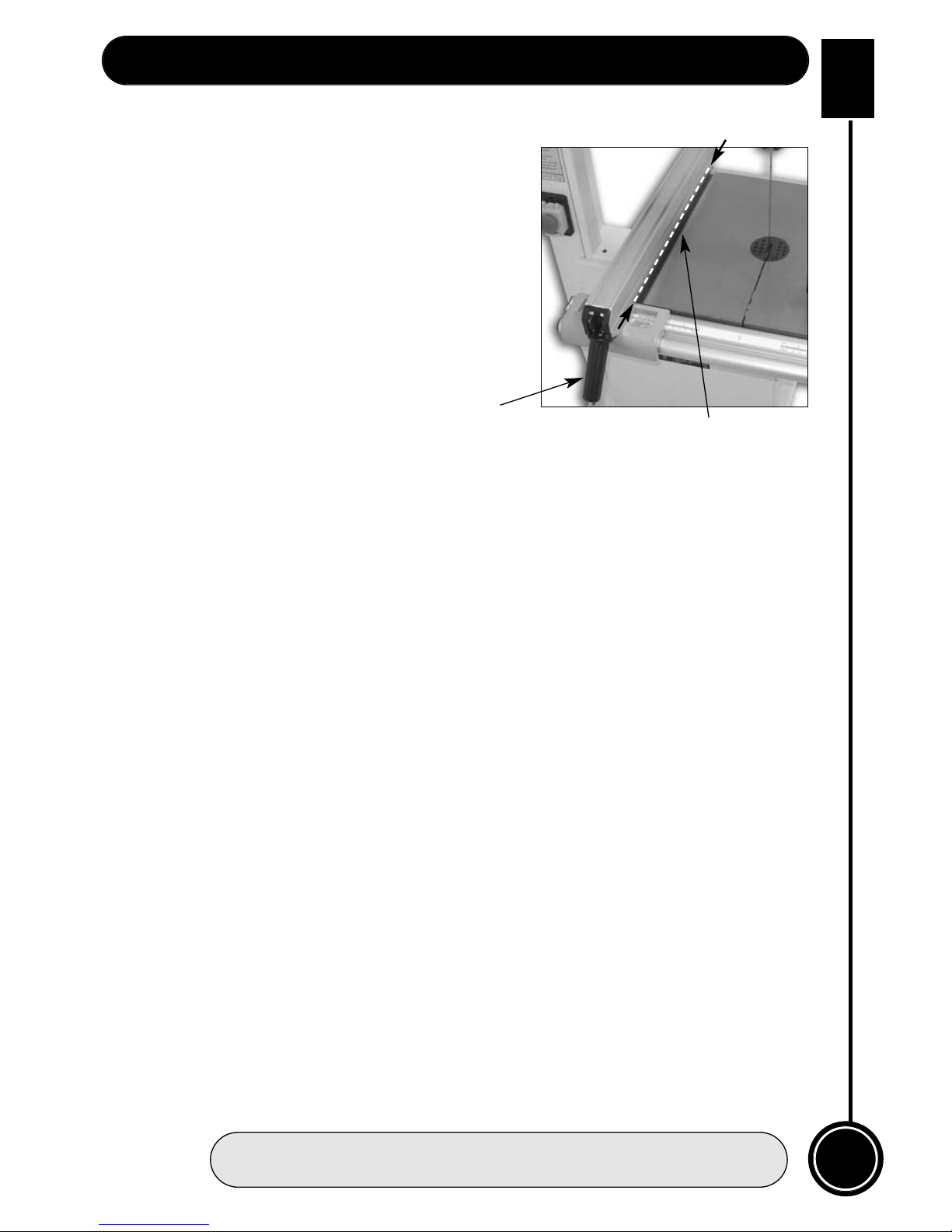
To make sure the fence is at 90°, line up the guide fence with the edge of the table slot ‘T’
(See fig 14). If you find the fence is out of alignment follow the steps on the opposite page.
Page 21
WHITE
AXMINSTER
W
21
Setting Up the Saw...
FREEPHONE 0800 371822
Setting the fence
1. Clamp down the fence by pushing the locking
lever down.
2. Loosen the fence rail by undoing
the four hex bolts. (See fig 1a)
3. Adjust the fence rail until the guide fence rail is
in line with the table slot. (See fig 14) Re-tighten
the hex bolts. (Do Not overtighten) then unlock
the fence by lifting the locking lever up.
Setting the blade guides
Lower the upper blade guide to approximately 1
1
/2
”(38mm) above the table. Clamp in place.
Loosen the two bolts marked ‘A’ (see fig 10) holding the guide assembly in place and adjust
the back to front position so that the leading edges of the side guide bearings are
approximately 1.5 mm behind the gullets of the saw blade. Re-tighten the bolts. Loosen the
cross point screw (see fig 9) in the rear bearing clamp and adjust the thrust bearing to
approximately 1mm behind the blade, tighten the screw.
(Note that the rear thrust bearing is mounted on a ‘cranked’ arm which can pivot; ensure
that when you clamp the arm in position, the blade is running approximately midway
between the centre and the outside edge of the bearing). (Check the symmetry with the
bottom thrust bearing).? Loosen the two bolts (marked ‘B’ fig 10) holding the guide
bearings (10mm spanner) and move to approximately 0.5 mm from each side of the blade.
Tighten the bolts. Gently push the blade back against the thrust bearing (use a scrap of
wood, et al,) and check that the side bearings are still behind the teeth of the blade. Loosen
the bolt (bolt ‘C’ fig 12) holding the lower blade guide assembly in place and position
similarly to the upper guide assembly. Tighten the bolt. Loosen the clamping screw (screw
‘D’ see fig12) of the rear thrust bearing (cross point screwdriver). Move it forward until it
touches the back of the blade; gently push the blade back against the upper thrust bearing,
this should move the lower thrust bearing back in line with upper bearing; tighten the
clamping screw. Adjust the lower side blade guides, and set them similarly to the upper
guides, using a cross point screwdriver to release and tighten the clamping screws
(marked ‘E’ fig 12). (You may find it easier to adjust the lower guide assembly if you remove
the plastic safety box that is screwed to the lower guide mounting. Remove by unfastening
the screw shown in (fig.11). Replace after all adjustments have been made. When all
adjustments have been made, recheck that when the blade is pressed back against the
thrust bearings, both the upper and lower side guides are still behind the teeth of the saw.
(This is imperative in the case of the lower guides as these are steel rods, and if they
impact with the saw teeth…………. I leave it to your imagination.).
When all adjustments are complete replace the table insert. Re-connect the power, switch
the saw on, allow to run for several minutes, check that the blade is still tracking correctly,
there is no excessive vibration, etc., etc. Switch off. The saw is ready to be used. Now
please read the Instruction Manual.
Fig 14
Table ‘T’ slot
Locking lever
Page 22
22
WHITE
AXMINSTER
W
Operating Instructions...
www.axminster.co.uk
!
DISCONNECT THE MACHINE FROM THE MAINS SUPPLY
1. Make sure you have read and fully understood the General instructions and safety precautions
that are printed in the preceding pages of this manual.
2. Before connecting the machine to the supply; check the tool for obvious signs of damage, paying
particular attention to the plug and the power cable. Rectify or have rectified any damage you discover.
Check that the blade you are using is the correct one for the job in hand. Change the blade if necessary.
Check the blade is not damaged; is clean, sharp, tracks properly and is correctly tensioned.
3. Set the upper blade guide to approximately 12mm (1/2”) above the height of the workpiece.
4. Check (especially on site), that there are no foreign objects e.g. old nails, screws, small stones etc
embedded in the material you are about to cut.
5. Check that all accessories, tools etc., that have been used to set the machine up, are removed and set
carefully aside or stowed away correctly.
6. Ensure the machine is switched off. Plug the power cable into a correctly rated switched socket outlet.
If extension leads are being used, check these for damage, do not use if damaged; if you are working
outside, check that any extension cables in use are rated for outside work. Switch on. Allow the saw to
run up to speed.
7. Make sure that the material you are about to cut is within the machine capacity, and the cut you are
about to make is within the blades’ capabilities, e.g. don’t try and cut a 1” radius curve using a 5/8” blade.
8. Make sure the blade is not in contact with the material when you start the saw. Start the cutting
operation. Do not try to cut too quickly; the correct cutting speed, if one could be so precise, would
never see the blade pushed back against the thrust bearing, the saw would cut and clear the saw line at
the rate the workpiece was fed into it. If you notice that you require more and more pressure to effect the
cut, and the blade is in continual contact with the thrust bearing, the chances are the blade is becoming
blunt. Check and change if necessary. Do not let go of the workpiece, if you have to change your grip,
make sure one hand is holding the material at all times.
9. If you are cutting long pieces of material think about sawing cutouts (i.e. a saw cut from the edge of the
material to the saw line) along the saw line so that you can discard the offcuts as you progress down the
saw line.
10. Observe the old woodworkers’ adage of never allowing your hand/fingers within one handbreadth of
the blade.
11. If you have to cut very small pieces of material, arrange or manufacture some form of ‘shoe’ to carry
the timber. If the workpiece is exceptionally small, find something to use as a sacrificial carrier and mount
the workpiece on it with double sided tape, or similar.
12. Remember to check the blade tension after a new blade has been ‘working’ for 30-60 mins. The blade
will ‘stretch’ slightly when new.
Page 23
WHITE
AXMINSTER
W
23
Operating Instructions (Continued)...
FREEPHONE 0800 371822
MAKE SURE THE SAW IS DISCONNECTED FROM THE SUPPLY.
Put the table back to the level position if it has been tilted. Set the upper blade guide assembly
approximately midway in the throat. Open the top and bottom covering doors. Remove the table insert.
Loosen the 4 butterfly bolts that hold the fence guide rail to the table, and remove the rail. Slacken the
blade tension by turning the blade tensioning wheel anti-clockwise, until the blade can be easily
slipped off the wheels. Remove the blade carefully, “wriggling” it clear of the upper blade guard and
through the red plastic lower blade guard and out through the slot in the table. NOW is an excellent
time to clean out the interior of the machine, remove the impacted ‘crud’ from the tyres, apply a little
light oil to the screw threads of the blade and drive belt tensioners, and the tracking control. The
pivots and the slides of the top wheel mounting assembly and the captive stub axle of the drive belt
tensioner in its slot could likewise be lightly oiled. If you are fitting a new blade; it will have been
supplied to you “folded”, bound together in this configuration with tape or tie wrap. Be very cautious
when you “unfold” the blade; it tends to ‘spring’ open, blade and teeth going everywhere.
Also check that the blade did not “unfold” inside out. i.e. looking at the right side front of the loop, the
teeth should be on the front of the blade, and pointing down. If you can’t arrive at this view, turn the
blade inside out from its current position and look again. Hold the blade approximately midway on
either side of the loop and feed it into the table slot, when you get to the table insert cutout void, work
the left side of the loop into the slot in the guard in the neck of the main saw frame. “Wriggle” the
righthand side of the blade through the slot in the red plastic lower guard and through the guard on
the upper blade guide assembly. Ease the blade over the wheels, and locate the blade in the blade
guides. Apply some tension to the blade. Turn the top wheel by hand to ensure the blade will not skip
off the wheels and the blade is travelling in the blade guides. Apply a little more tension and check
again by once again spinning the upper saw wheel by hand. When you are sure that the blade is “ON”
and stable, re-fit the fence guide rail, re-fit the table insert and carry out the procedures as detailed in
Setting up the saw.
13. Do not release the tension on the saw blade when work is complete. The blades and the main saw
frame do not respond kindly to constant changes in stress and tension. Only release the tension to
change the blade or if the blade is to be removed because the machine is to be ‘mothballed’ for a
lengthy time period. (The blade in tension over a long period of non-use will cause the tyres to develop
‘flat’ spots).
N.B. IF THE SAW JAMS! Switch off immediately. Open the saw cut, either by pulling
apart or driving a wedge in close to the back of the blade. Try to wriggle the blade free of the
saw, if this is not possible; check that the saw is free in the cut, start the saw, allow it to run
up to speed and ‘cut out’ as quickly as possible. (The removal of the ‘offcut’ may well prevent
the saw jamming again if you resume the original cut).
!
!
Changing the Saw Blade...
Page 24
WHITE
AXMINSTER
W
1998
700124
www.axminster.co.uk
Axminster Devon EX13 5PH UK
FREEPHONE 0800 371822
Axminster Reference No:AWBB
AWBB Bandsaw
 Loading...