

Page 1
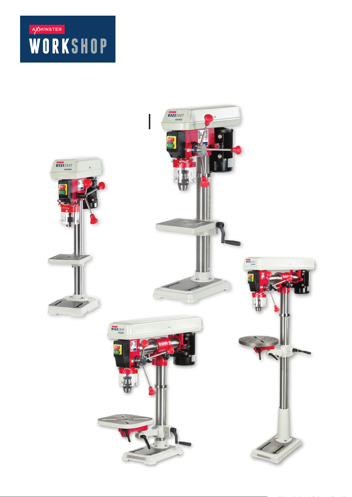
Pillar Drills
User manual
AW285PD Code 107690
AW315PD Code 107691
AW220RD Code 107692
AW680RD Code 107693
Original Instructions
AW285PD
AW315PD
AW220RD
AW680RD
AT: 12/08/2025
BOOK VERSION: 06
Page 2
INDEX OF CONTENTS
What’s Included
03-06
General Safety Instructions for 230V Machines 07
General Safety Instructions for Drilling Machines 07
Specification 08
Assembly
Illustration and Parts Description
09-13
14 - 17
Changing the Speed 18
Removing Keyless Chuck 19
Maintenance 20
Speed Select Tables 21
Drill Speed Material Table 22
Troubleshooting 23
Exploded Diagrams/Lists
24 - 31
Wiring Diagram 32
Notes
CE/UKCA Declaration of Conformity
33
34-35
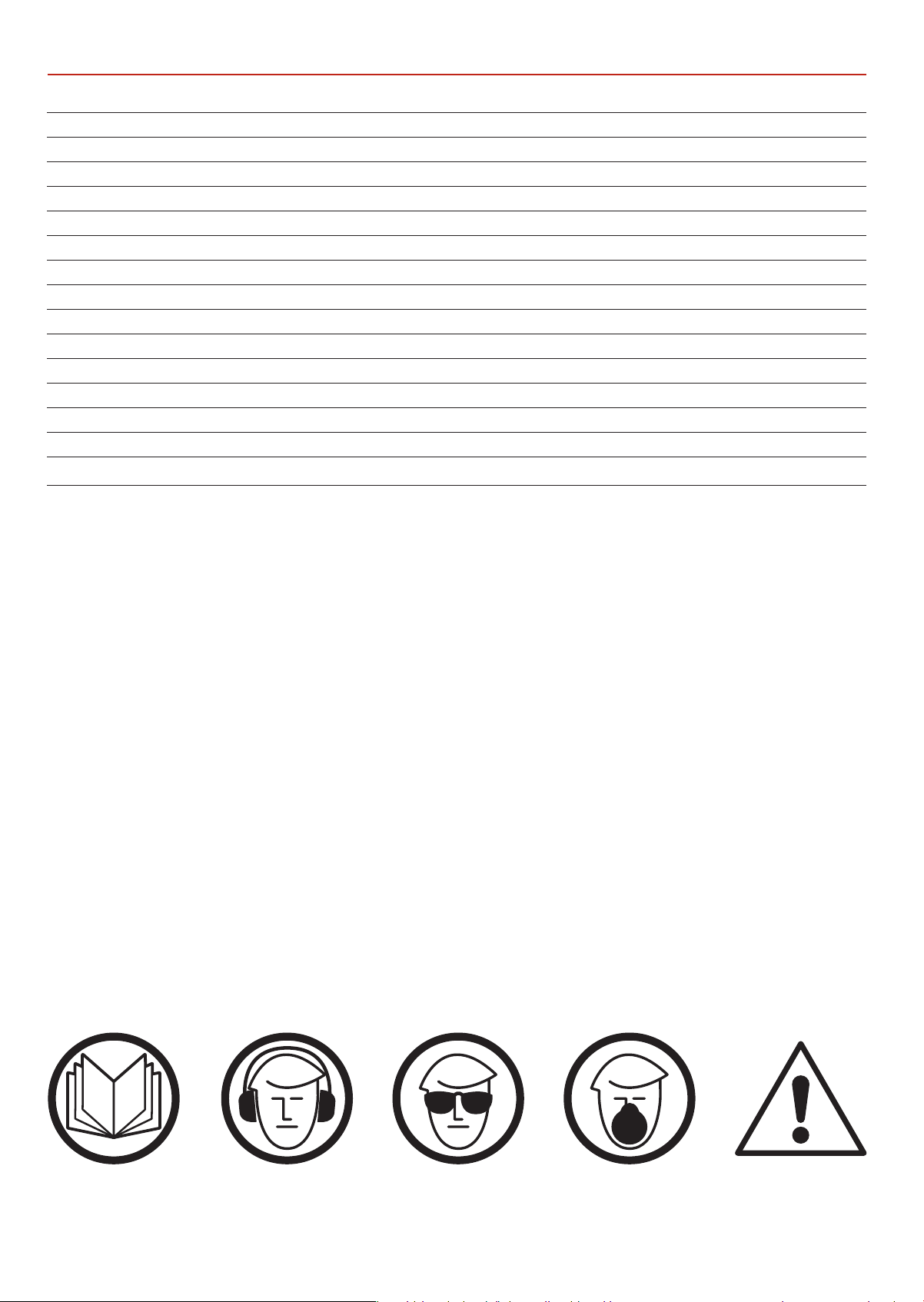
The symbols below advise the correct safety procedures when using this machine.
Fully read manual
and safety instructions
before use
Ear protection
should be worn
Eye protection
should be worn
2
Dust mask
should be worn
HAZARD
Page 3
WHAT’S INCLUDED
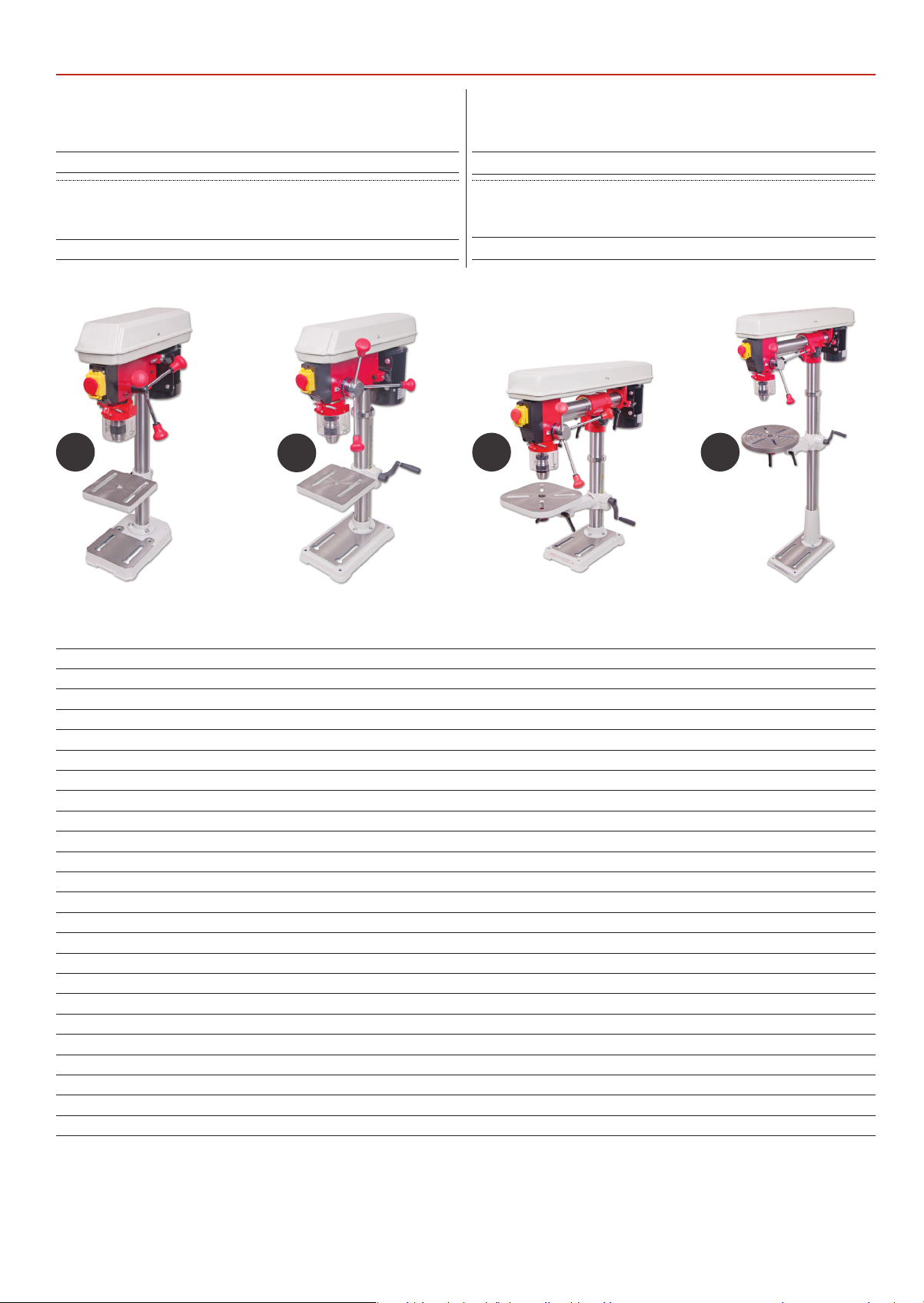
Model Number AW285PD (ZQJ4113A)
Quantity Item Part
1 Small Bench Pillar Drill A
Model Number AW220RD (ZQJ3116)
Quantity Item Part
1 Bench Radial Drill C
A
B
Model Number AW315PD (ZQJ4116Q)
Quantity Item Part
1 Medium Bench Pillar Drill B
Model Number AW680RD (ZQJ3116A)
Quantity Item Part
1 Floor Radial Drill D
C D
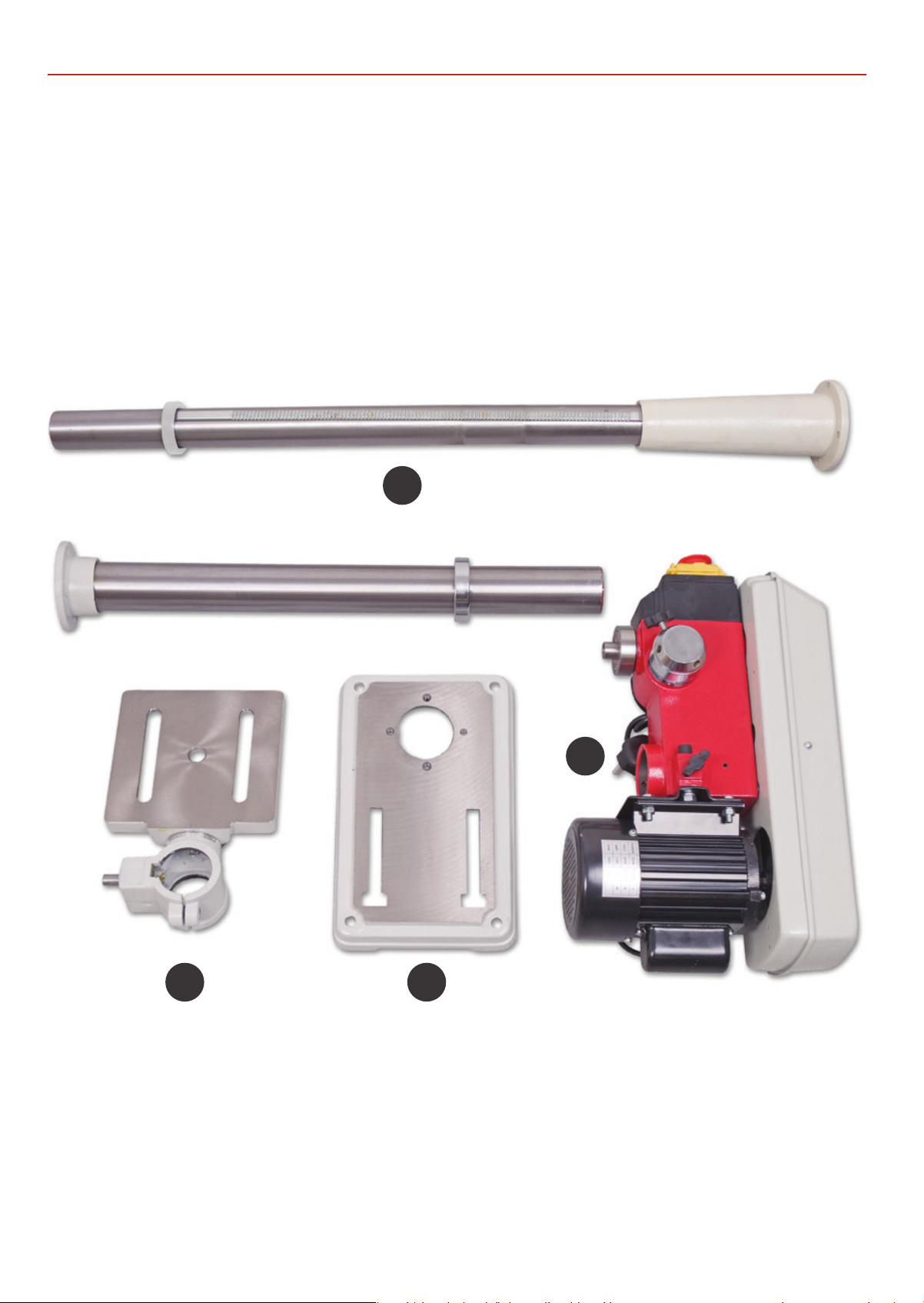
Box Containing:
1 Pillar for drill head complete with mounting
flange, rise and fall rack and retaining ring 1
1 Drill table with mounting flange 2 (107691 ONLY)
2a (107690 ONLY)
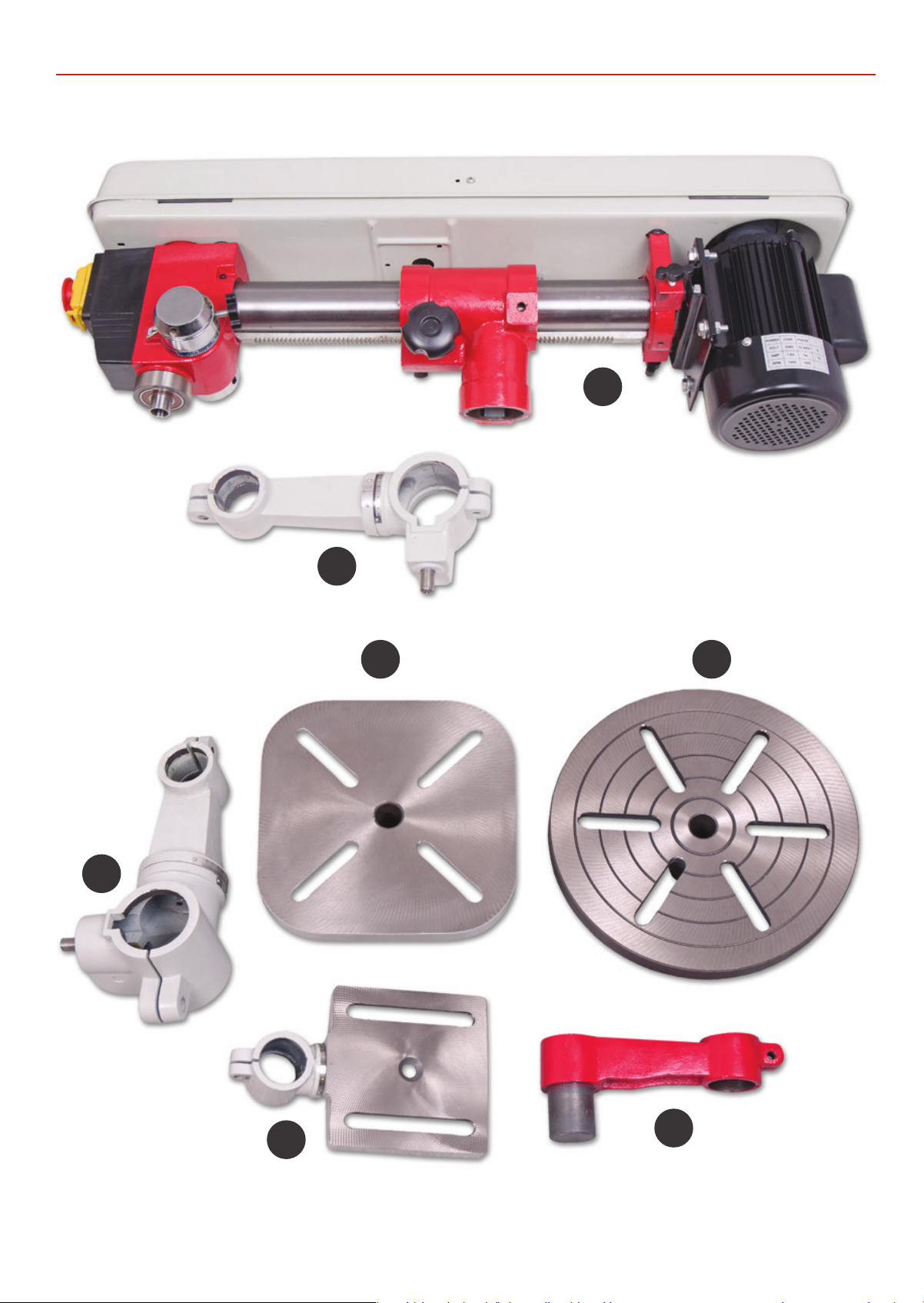
1 Drill table extension bracket arm 2b (107693 ONLY)
2c (107692 ONLY)
1 Extension bracket arm 2d (107692 and 107693 ONLY)
1 Drill table square 2e (107692 ONLY)
Drill table round 2f (107693 ONLY)
1 Base 3
1 Pillar drill head 4
1 Radial drill head with spacer block 4a (107692 and 107693 ONLY)
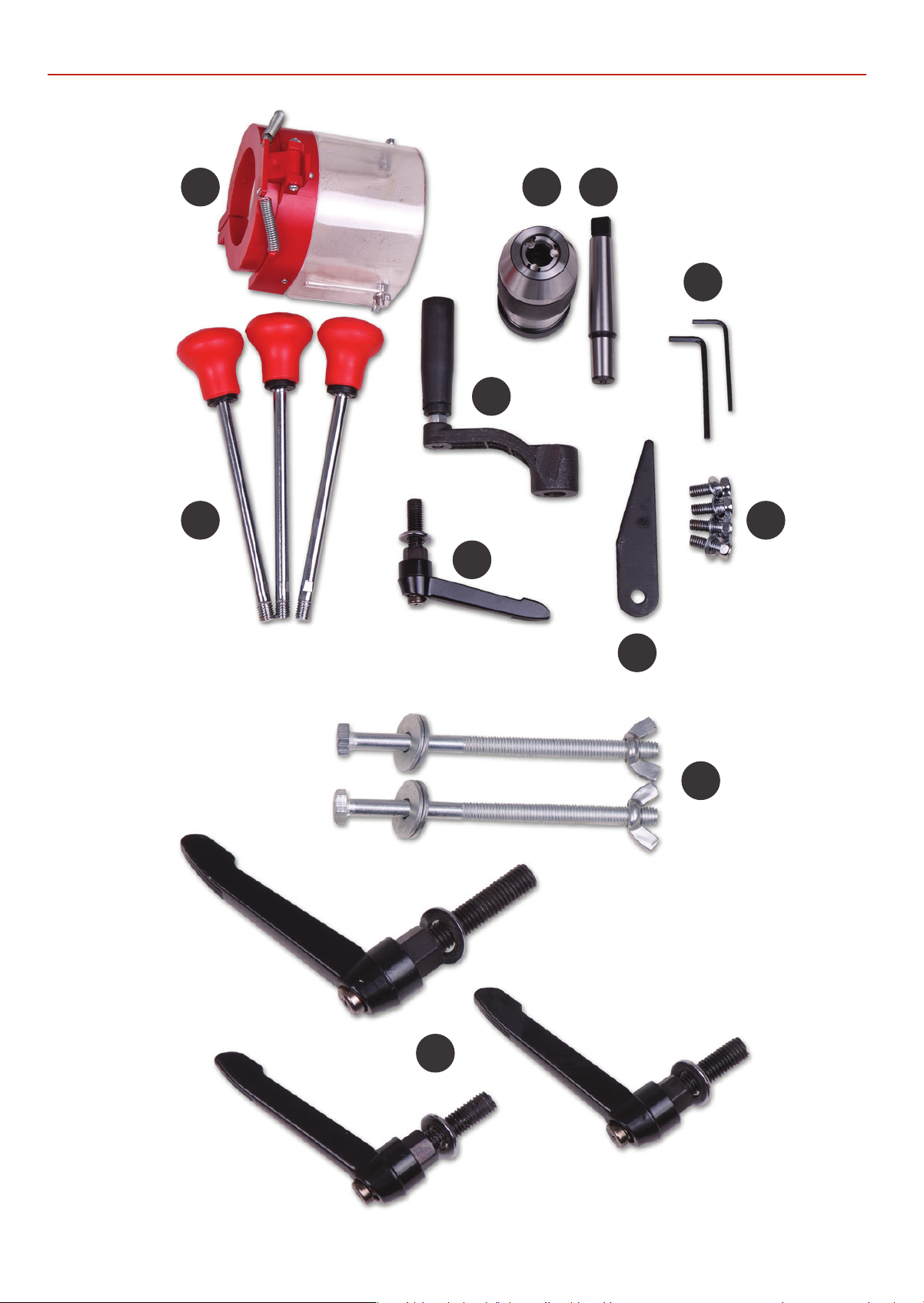
1 Drill guard assembly 5
3 Lever feed handles 6
1 Keyless chuck 7
1 Morse taper arbor for chuck assembly 8
1 Crank handle for table rise and fall mechanism 9
Lift and shift handle clamps for the rise and fall mechanism,
drill table and radial drill head column clamps 10
1 Morse taper drift 11
4 M8 x 20mm + washers 12 (107691 and 107692 ONLY)
4 M8 x 35mm +washers 12 (107693 ONLY)
3 M8 x 20mm + washers 12 (107690 ONLY)
2 Hex Keys 3-4mm 13
2 Table clamping threaded bolts washers and wing nuts 14 (107693 ONLY)
3
Page 4
WHAT’S INCLUDED
1
2 3
4
4
Page 5
WHAT’S INCLUDED
4a
2b
2c
2e
2f
2a
2d
5
Page 6
WHAT’S INCLUDED
5
6
7 8
13
9
12
10
10
11
14
6
Page 7

GENERAL SAFETY INSTRUCTIONS FOR 230V MACHINES
The following will enable you to observe good working
practices, keep yourself and fellow workers safe and maintain
your tools and equipment in good working order.
WARNING!! KEEP TOOLS AND EQUIPMENT
OUT OF REACH OF YOUNG CHILDREN
KEEP WORK AREA AS UNCLUTTERED AS IS
PRACTICAL. UNDER NO CIRCUMSTANCES SHOULD
CHILDREN BE ALLOWED IN WORK AREAS.
Mains Powered Tools
• Tools are supplied with an attached 13 Amp UK 3 pin plug,
fitted with 13 amp fuse.
•
Inspect the cable and plug to ensuree that neither are
damaged. Repair if necessary by a suitably qualified person.
• Do not use when or wher
Workplace
• Do not use 230V a.c. powered tools anywhere
within a site area that is flooded.
• Keep machine clean.
Leave machine unplugged until work is about to commence.
•
• Always disconnect by pulling on the plug body and not the
cable.
e it is liable to get wet.
• Carry out a final check e.g. check the cutting tool
is securely tightened in the machine and the correct
speed and function set.
• Ensure you are comfortable before you start work,
balanced, not reaching etc.
• Wear appropriate safety clothing, goggles, gloves,
masks etc. Wear ear defenders at all times.
• If you have long hair wear a hair net or helmet to prevent it
being caught up in the rotating parts of the machine.
•
Consideration should be given to the removal of rings and
wristwatches.
• Consideration should also be given to non-slip footwear etc.
• If another person is to use the machine, ensure they are
suitably qualified to use it.
• Do not use the machine if you are tired or distracted
• Do not use this machine within the designated safety areas
of flammable liquid stores or in areas where there may be
tile gases.
vola
• Check cutters are correct type and size, are undamaged
and are kept clean and sharp, this will maintain their
operating performance and lessen the loading on the
machine
OBSERVE…. make sure you know what is happening
•
around you and USE YOUR COMMON SENSE.
.
GENERAL SAFETY INSTRUCTIONS FOR DRILLING MACHINES
1. DO NOT operate the machine without a preliminary
inspection.
2. CHECK that the speed is correct for the operation, and
upper drive belt cover is closed and fastened.
3. CHECK the drill bit is the correct size and type, is correctly
fitted and tightened in the chuck.
4. Make sure that the drillhead, the table bracket arm, the table
tilt and the table swivel clamps are all locked before any drilling.
5. DO NOT attempt to carry out any drilling operation on
material that has not been secured to the drill table, either by
vice or clamp.
6. Remove any tools (chuck key, spanners etc), that may have
been used in setting up operations and put them away.
7. Arrange the drilling operation so that the drill tip does not
come in contact with the table.
8. ALWAY S allow the drill to stop before removing drills or
swarf from around the job or the table.
9. NEVER remove ‘flying’ swarf strands from the drill whilst it is
turning.
10. It is a good precaution to wear eye protection when drilling,
especially using small drills, or very hard material.
11. Avoid wearing gloves when operating a drill press.
12. After the job is completed, remove all tool accessories,
check that drill bits are still sharp and re-use able.
13. Clean the machine thoroughly, including removing coolant
cutting compound.
14. Lightly coat all metal surfaces with a light oil.
15. Disconnect the machine from the supply. Secure the cable/
plug clear of the floor.
7
Page 8
SPECIFICATION
Code 107690
Model AW285PD
Rating Workshop
Power 350W 50Hz (230V 1ph)
Speed Range (5) 600 - 2,500 rpm
Swing 210 mm
Chuck Size / Type 1-13 mm / Keyless
Chuck Travel 50 mm
Diameter of Column 46 mm
Max Chuck to Table 285 mm
Max Chuck to Base 380 mm
Table Tilt -45˚ to +45˚
Base Size 285 x 185 mm
Collar Diameter 40 mm
Quill Diameter 45 mm
Table Size 165 x 165 mm
Overall L x W x H 500 x 280 x 735 mm
Weight 26 kg
Code 107692
Model AW220RD
Rating Workshop
Power 550W 50Hz (230V 1ph)
Speed Range (5) 500-2,450 rpm
Swing 840 mm
Chuck Size / Type 1-16 mm / Keyless
Throat 420 mm
Taper 2 MT
Chuck Travel 80 mm
Horizontal Arm Travel 320 mm
Diameter of Column 60 mm
Max Chuck to Table 220 mm
Max Chuck to Base 375 mm
Table Tilt -45˚ to +45˚
Base Size 215 x 340 mm
Quill Diameter 40 mm
Table Size 230 x 210 mm
Overall L x W x H 840 x 320 x 790 mm
Weight 37 kg
Code 107691
Model AW315PD
Rating Workshop
Power 550W 50Hz (230V 1ph)
Speed Range (12) 210-2,580rpm
Swing 254mm
Chuck Size / Type 1-16 mm / Keyless
Throat 127 mm
Taper 2 MT
Chuck Travel 60 mm
Diameter of Column 60 mm
Collar Diameter 60 mm
Max Chuck to Table 315 mm
Max Chuck to Base 430 mm
Table Tilt -45˚ to +45˚
Base Size 340 x 210 mm
Quill Diameter 40 mm
Table Size 240 x 240 mm
Overall L x W x H 530 x 280 x 840 mm
Weight 37 kg
Code 107693
Model AW680RD
Rating Workshop
Power 550W 50Hz (230V 1ph)
Speed Range (5) 500-2,450 rpm
Swing 840 mm
Chuck Size / Type 1-16 mm / Keyless
Throat 420 mm
Taper 2 MT
Chuck Travel 80 mm
Horizontal Arm Travel 320 mm
Diameter of Column 70 mm
Max Chuck to Table 680 mm
Max Chuck to Base 1,180 mm
Table Tilt -45˚ to +45˚
Base Size 450 x 270 mm
Quill Diameter 40 mm
Table Size 310 mm diameter
Overall L x W x H 820 x 320 x 1,630 mm
Weight 61 kg
8
Page 9
ASSEMBLY
Having unpacked your machine and accessories, check the
contents against the equipment list ”What’s Included”, if there
are any discrepancies, please contact Axminster Tool Centre
using the guide on our website.
PLEASE DISPOSE OF THE PACKAGING RESPONSIBLY;
MUCH OF THE MATERIAL IS RECYCLABLE
The machine and its accessories arrive coated with heavy
corrosion preventative grease and wax paper or plastic
wrapping. These will need to be cleaned from the machine,
its components and accessories prior to it being set up and
commissioned. Use water soluble degreaser to remove. Be
warned, it will stain if you splash clothing etc. After cleaning,
lightly coat exposed metal.
WARNING! WEAR OVERALLS AND EYE PROTECTION!
surfaces of the machine with a thin layer of light machine oil.
N.B If you used water soluble de greaser make sure you apply
this thin film swiftly.
Please read the Instruction Manual prior to using your new
machine; as well as the installation procedure, there are
daily and periodic maintenance recommendations to help
you keep your machine in good condition and prolong life.
Keep this instruction manual accessible for others who may
also be required to use the machine.
Fig 02
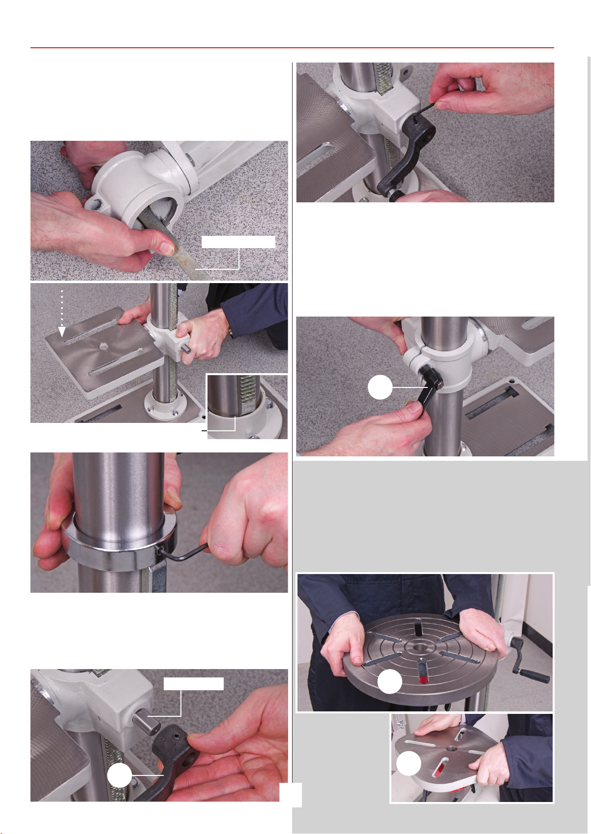
2. Take the drill table mounting bracket arm (2,2a,2b,2c) and
twist the worm drive shaft with your fingers so that the whole
shaft protrudes from the casting and the worm gear
itself is clear of the square recess in the main body of the
casting (see fig 3).
Fig 03-04
Pinion
Worm gear
Please read through the section entitled Illustration and
parts description, to identify the parts easily.
WARNING! THE DRILL HEAD IS A HEAVY PIECE OF
MACHINERY, YOU ARE ADVISED TO HAVE HELP TO
LIFT IT CLEAR OF THE BOX AND TO FIT.
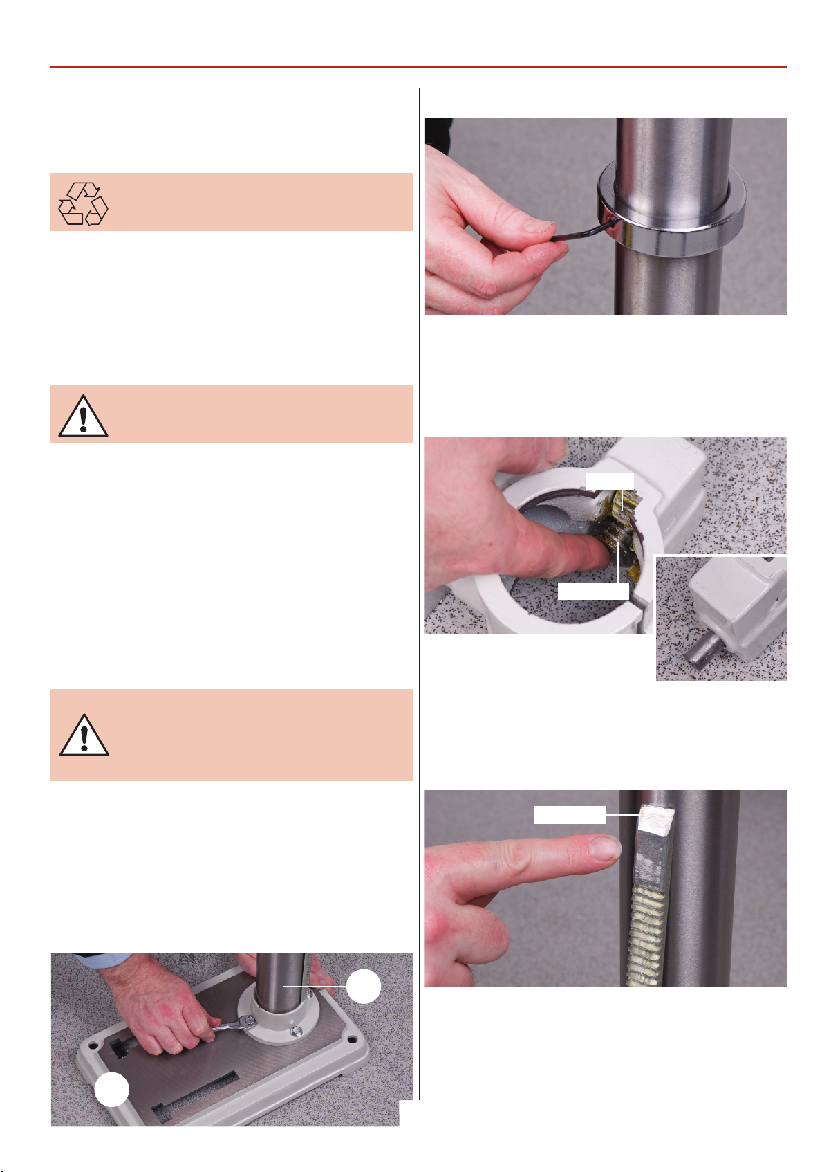
1. Place the base (3) on the bench or floor and place the
mounting flange of the column (1) onto the seating flange of
the base, align the holes. Use the four Hex bolts and secure the
column to the base, see fig 1. Loosen the grub screw holding
the chamfered retaining collar on the column with the supplied
Hex key, place it and the rise and fall rack assembly aside,
see fig 2.
Fig 01
1
3
9
3. Pick up the rise and fall gear rack,
identify the top and the bottom, (the
rack gearing is cut asymmetrically, with
the gear cut extending closer to the bottom), make sure you
have the rack the right way up, as it will allow you to drive the
drill table up and down over its full range, see fig 5.
Worm gear shaft
Fig 05
Top of rack
4. Fit the rise and fall rack into the square recess in the
mounting body casting, ensure that it is engaged with the
pinion, see figs 6 and lower the combined mechanism over the
column (1). Allow it to slide down the column until the rise and
fall rack is located in the cup chamfer in the top of the mounting flange, see figs 7. Replace the cup chamfered retaining
Continues Over....
Page 10
ASSEMBLY
collar over the column and slide it down onto the top of the
rack. Lock it in place with the grub screw, ensuring that it has
captured the upper end of the rack securely, but not too tight
that the rack cannot be swivelled around the pillar see fig 8 .
Fig 06-07
Rise and fall rack
6. Check that the bracket can be driven up and down the
column and can swivel around the pillar. Locate the lift and shift
clamping handle (10) and scr
rear of the mounting bracket arm (2) and tighten, see fig 11.
Check it has ‘pinched’ up on the column and the bracket is
immobile; both in its up and down travel and swivel movement.
ew it into the threaded hole to the
Fig 11
cup chamfer
Fig 08
5. Locate and fit the crank handle (9) to the shaft, ensuring that
you tighten the grub screw onto the machined flat on the shaft,
this will keep the worm gear in position, see figs 9-10.
Fig 09
10
Radial Standing Drill Only
7. Slot the drill table (2e or 2f) into the machined hole to the
front of the mounting arm (2b and 2c) and screw a lift and shift
clamping handle (10) into to the threaded hole beneath the
table and tighten, see figs 12-13. Check it has ‘pinched’ up on
the drill table spigot and the drill table is immobile.
Fig 12-13-14
9
Machined flat
2f
2e
10
Page 11
10
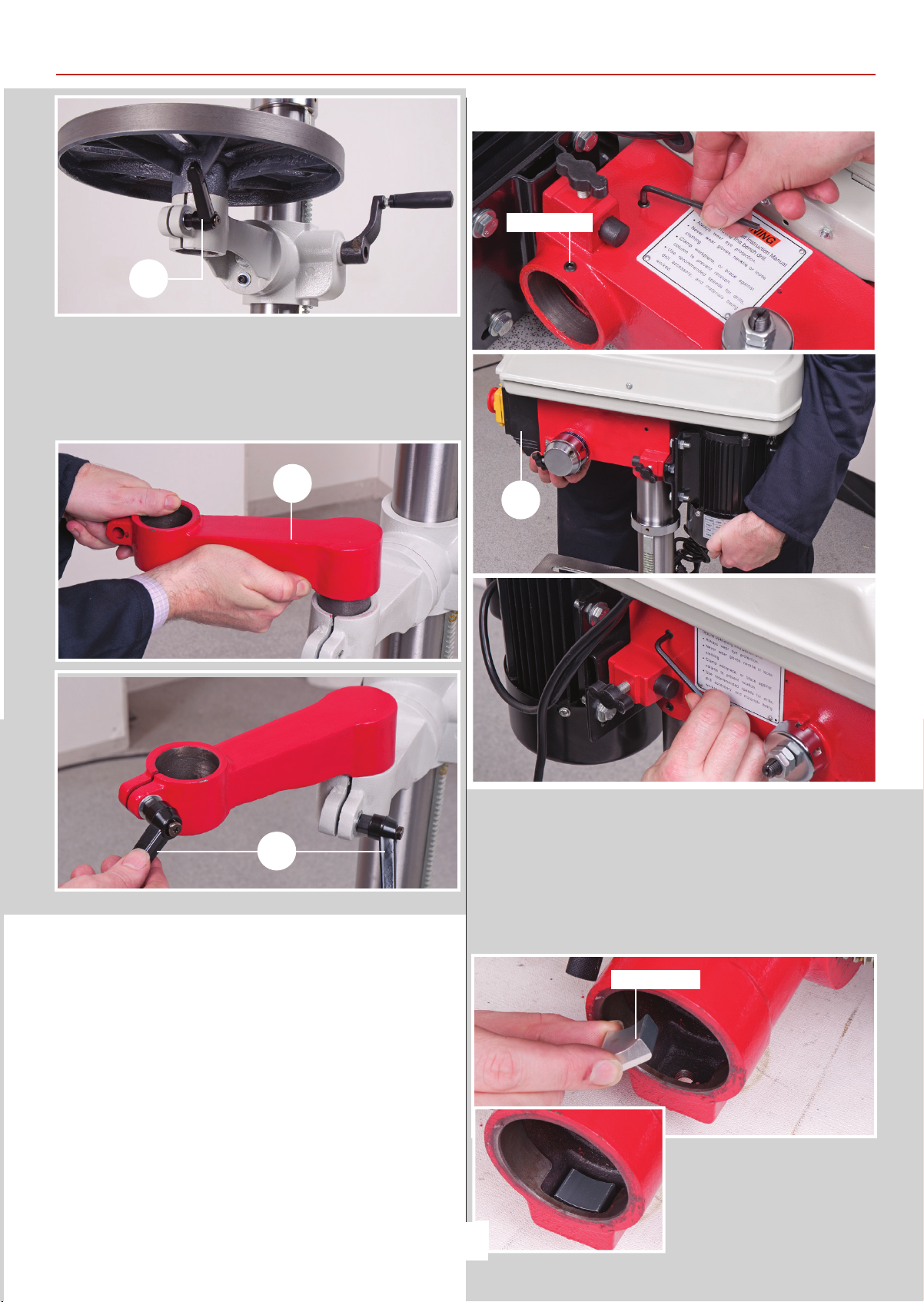
Note: On the two radial drills fit the extension arm (2d)
into the mounting arm (2b and 2c) then the tables, see figs
14-15-16.
Fig 15-16
2d
ASSEMBLY
Fig 17-18-19
Grub screw
4
10
Mounting the Drill Head
1. Ensure that the two hex socket grub screws that lock the
head in place on the column are withdrawn and will not foul
the column (1) when the head is fitted, see fig 17. Put the lower
assembly (you have just been working on) in the designated
position, make sure it is stable and lift the drillhead (4) over the
column (1) and let it drop into place, see fig 18. Set the drill head
approximately fore and aft and lock in position using the two
cap head grub screws mentioned earlier, see fig 19. Check that
the drillhead is immobile. Everything on the drilling machine is
now secured.
Radial Pillar Drill Head Only
2. Lay the drill head on its side, locate the column
spacer block and insert it into machined recess inside the base
of the drill head, see fig 20. Lift the drill head onto the column
as described above and secure using a lift and shift handle (10),
see figs 21.
Fig 20
Spacer block
Continues Over....
11
Page 12
ASSEMBLY
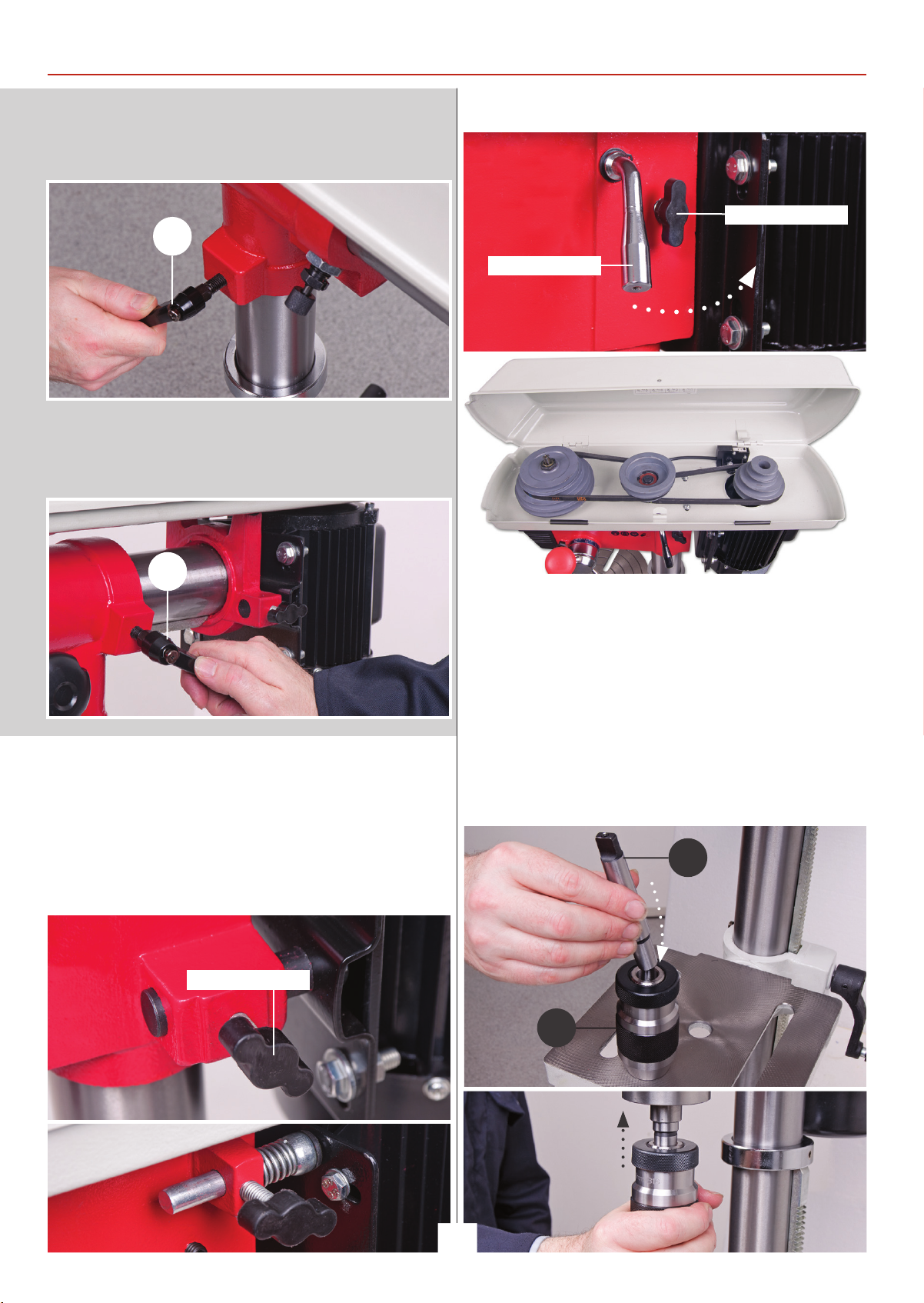
NOTE: Make sure the spacer block does not come out when
lifting the drill head onto the column!
Fig 21
10
3. Locate another lift and shift handle (10) and screw it into the
threaded hole for the Horizontal clamp assembly, see fig 22.
Fig 22
Fig 25-26
Motor yoke clamp
Tensioning lever
10
4. Open the pulley cover and check to see if the belt has been
tensioned. If not, loosen the two motor yoke locks and push the
motor back to tension the belt, see fig 23-24-25. For the floor
standing pillar drill head, move the tensioning lever back then
re-tighten the motor yoke locks to lock the motor in place, see
fig 25-26.
Fig 23-24
Motor yoke clamp
1-13mm Keyless Chuck AW285PD Only
Locate the chuck (7) and insert up over the morse taper arbor,
using a high faced mallet, lightly tap home.
3-16mm Keyless Chuck
Locate the morse taper arbor (8), insert the arbor into the
keyless chuck (7) then slot the assembly up into the quill.
Using a high faced mallet, lightly tap home, see fig 27-28.
Fig 27-28
8
12
7
Page 13
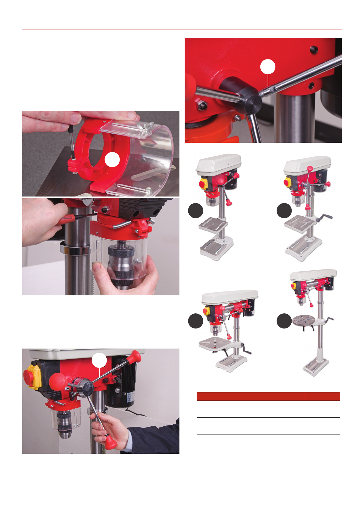
Drill Guard
Locate the drill guard assembly (5), loosen the Phillips screw
and nut to the rear of the guard, see fig 29 insert the assembly
up over the lower bearing flange of the quill until the assembly
is up against the drill casting, re-tighten the screw and nut to
lock the guard assembly in place, see fig 30.
Fig 29-30
5
ASSEMBLY
6
Lever Feed Handles
Locate the three lever feed handles (6) and screw them into the
threaded holes on the depth stop ring, see fig 31-32.
Fig 31-32
6
A B
D
E
13
Model Letter
AW285PD A
AW315PD B
AW220RD C
AW680RD D
Page 14
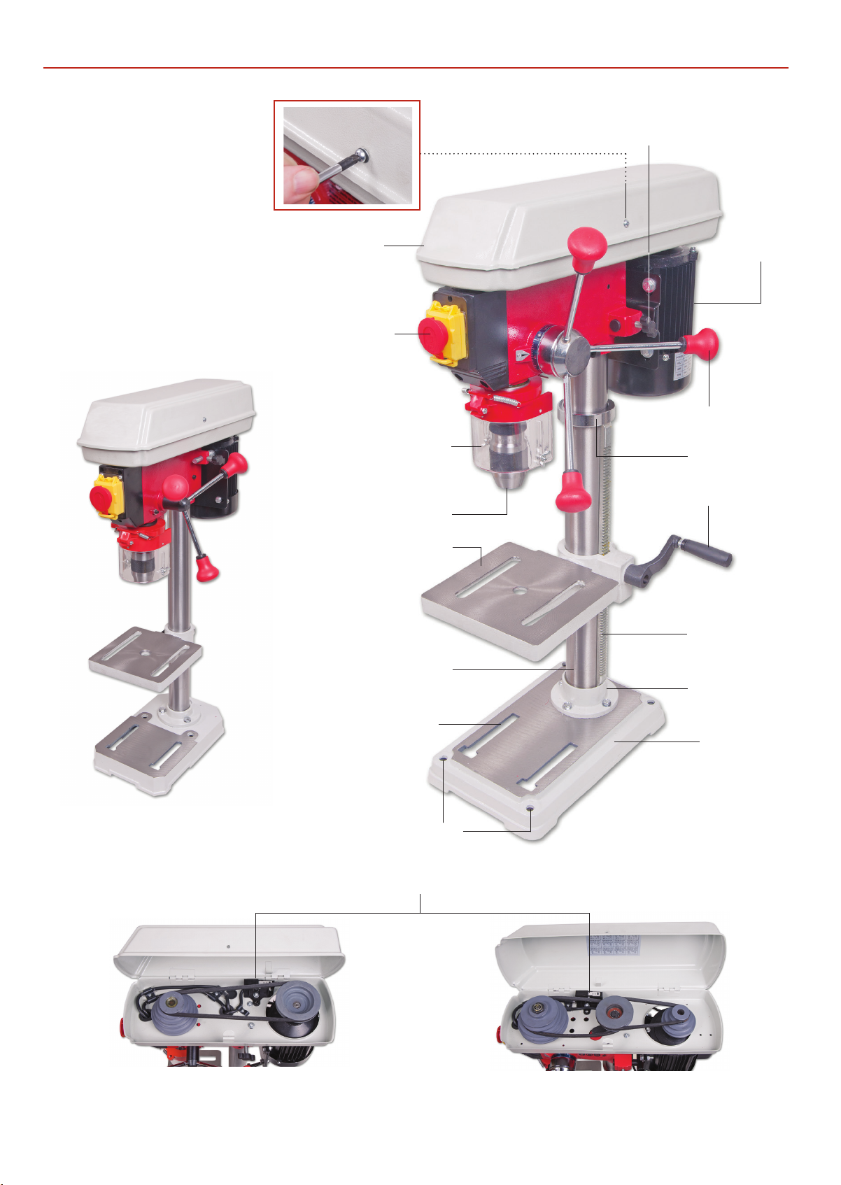
ILLUSTRATION AND PARTS DESCRIPTION
Belt cover securing screw
Motor yoke locking knob
Pulley drive belt cover
ON/OFF switch shroud
Chuck guard
Keyless chuck
Drill table
Motor
Lever feed handle
Retaining collar
Crank handle
Rise and fall rack
107690 AW285PD
Drill column
Base casting ‘T’ slot
Pillar drill securing holes
Micro switch
Mounting flange
Base casting
107691 AW315PD
107690 Drive Pulley
107691 Drive Pulley
14
Page 15
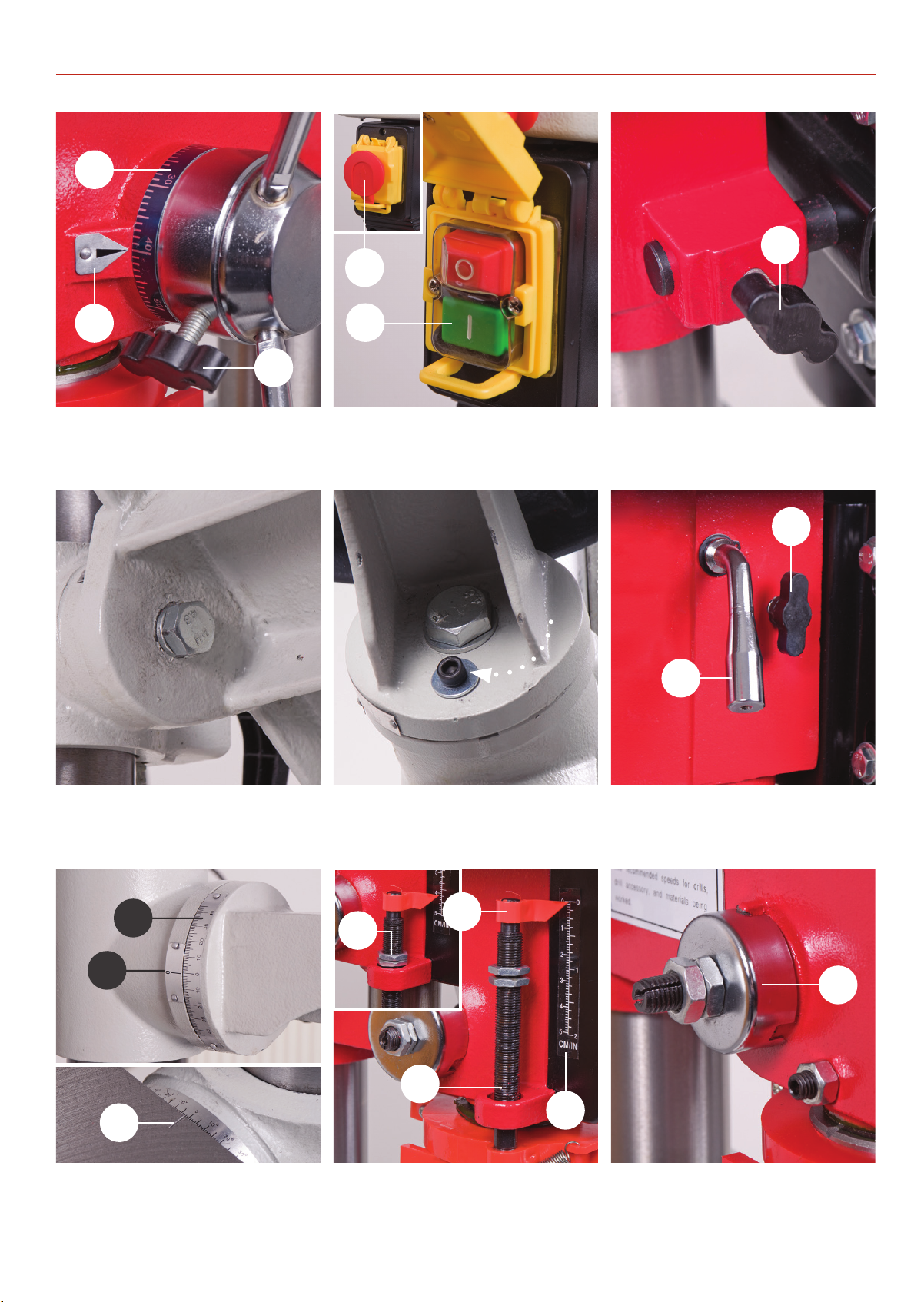
B
ILLUSTRATION AND PARTS DESCRIPTION
A
B
C
A
Depth stop clamp (A)
Depth scale (B), Depth scale pointer (C)
A
ON/OFF switch (A)
Emergency stop button (B)
Motor yoke clamp (A)
A
B
Table tilt locking bolt 90˚ Locking bolt Motor yoke clamp (A)
Drive belt tensioning lever (B)
A
D
C
B
A
B
B
Table tilt scale (A)
Table tilt pointer (B)
Depth stop assembly (A)
Depth stop scale (B), Depth stop nuts (C)
Pointer (D)
15
Quill rise and full return spring (A)
A
Page 16
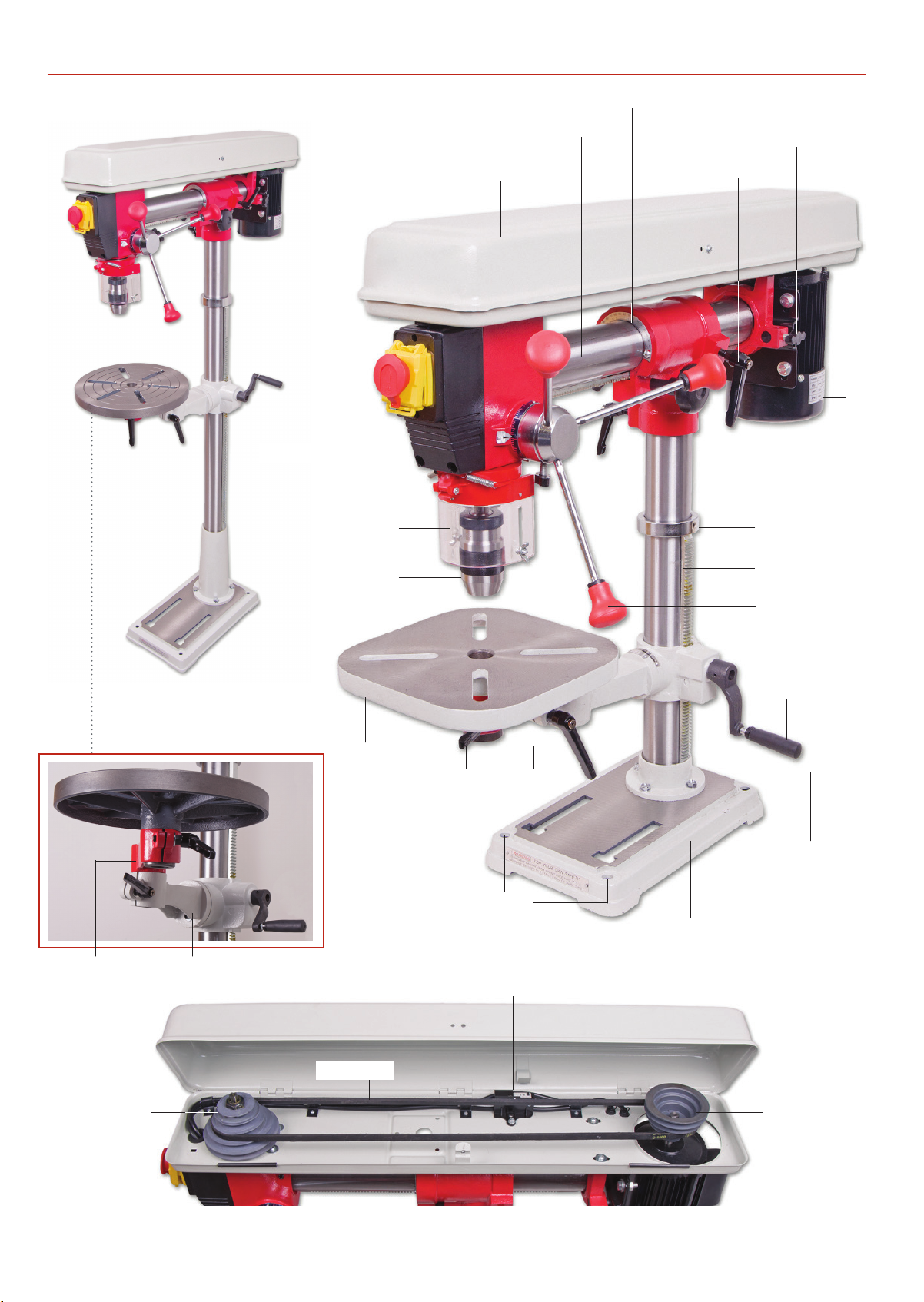
ILLUSTRATION AND PARTS DESCRIPTION
Vertical scale
ON/OFF switch shroud
Chuck guard
Keyless chuck
Horizontal column
Pulley drive belt cover
Motor yoke locking knob
Horizontal column lock
Motor
Drill column
Retaining collar
Rise and fall rack
107693 AW680RD
Extension arm Extension bracket arm
Lever feed handle
Crank handle
Drill table
Lift and shift handles
Base casting ‘T’ slot
Mounting flange
Pillar drill securing holes
Base casting
107692 AW220RD
Micro switch
Quill pulley
Pulley belt
Motor pulley
16
Page 17
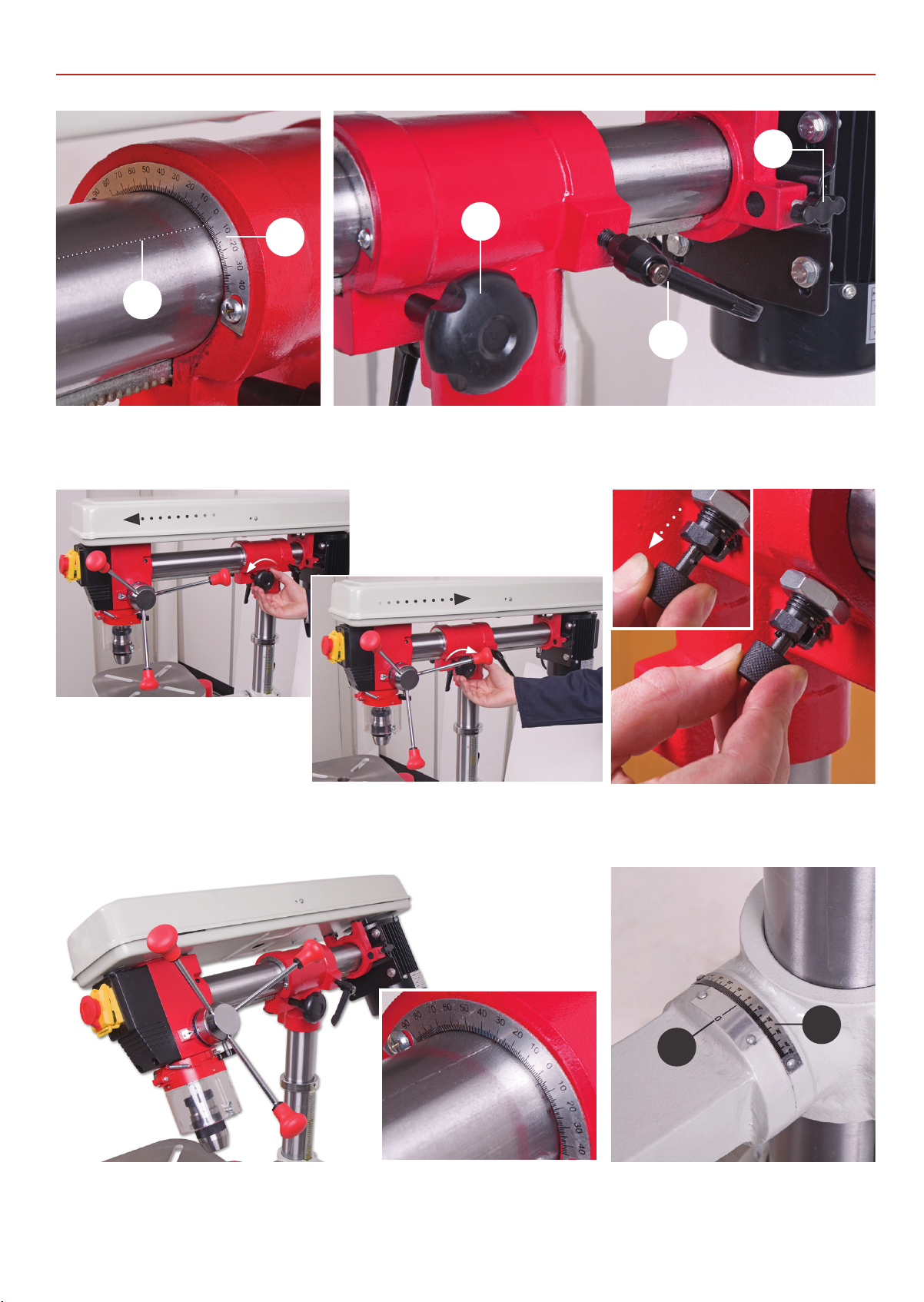
B
ILLUSTRATION AND PARTS DESCRIPTION
C
A
A
B
Vertical scale (A)
Column pointer (B)
Turn the horizontal adjusting knob
anti-clockwise to move the column forward
Horizontal column adjusting knob (A)
Horizontal column clamping handle (B), Motor yoke clamp (C)
Turn the horizontal adjusting knob
clockwise to move the column back
Vertical locking pin
Loosen the horizontal column clamping handle (B). Pull out the vertical locking pin to
un-lock the drill head column. Rotate + or - to the appropriate angle using the tilt pointer on
the column then retighten the horizontal clamping handle to lock the head in position.
17
A
B
Table tilt scale (A)
Table tilt pointer (B)
Page 18
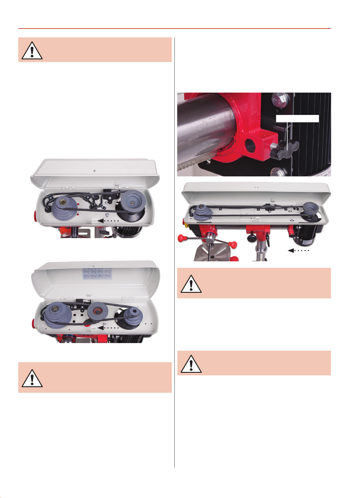
CHANGING THE SPEED
WARNING! DISCONNECT THE PILLAR DRILL FROM
THE MAINS SUPPLY BEFORE CONTINUING!
To release the tension, loosen the two motor yoke locks on
either side of drilll head, push the motor assembly up against
the drill head casting, thus releasing the tension on the pulleys,
see figs 33-34.
Refer to the (speed select table on page 21) and ascertain the
belt positions for speed required.
Fig 33-34
Radial Drills
To release the tension, loosen the motor yoke tensioning locks,
push the motor up against the drillhead casting, thus releasing
the tension on the pulleys, see fig 35-36.
Fig 35-36
Motor yoke lock
AW285PD Drive Pulley
AW315PD Drive Pulley
WARNING! TAKE CARE NOT TO TRAP YOUR FINGERS
WHEN REPOSITIONING THE BELT ON THE PULLEYS!
WARNING! TAKE CARE NOT TO TRAP YOUR FINGERS
WHEN REPOSITIONING THE BELT ON THE PULLEYS!
Turn the pulleys to check the belts move freely. Tension the
pulleys by pushing the motor assembly out and securing the
motor yoke butterfly knob to lock the motor assembly in
position. Lower the belt and pulley cover carefully, (remember
the micro switch).
RE-CONNECT THE SUPPLY AND SWITCH ON. CHECK
THE DRILL RUNS SMOOTHLY, NO HARD VIBRATION.
If all seems satisfactory, recommence drilling operations.
18
Page 19
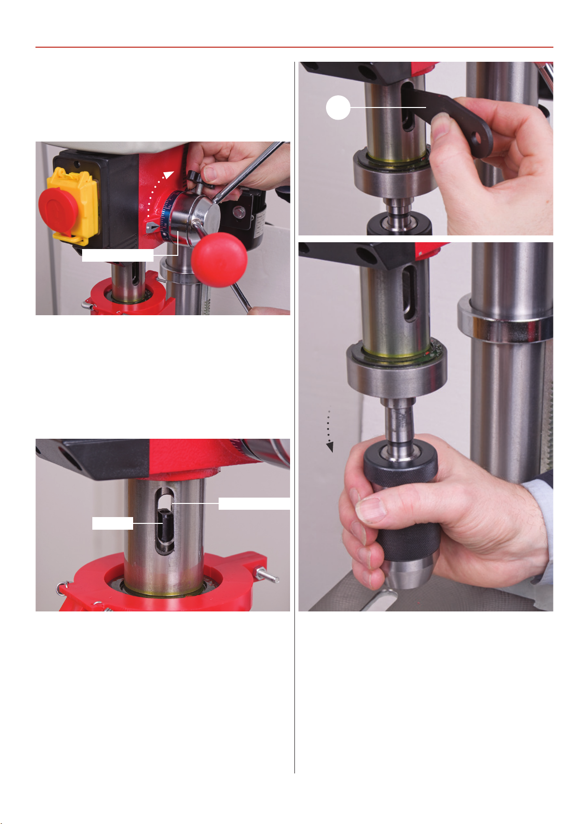
1. Lower the quill to its maximum depth by turning the lever
feed handle. While holding the handle turn the depth scale ring
(A) fully round and then tighten the butterfly depth stop clamp
(B) to lock the quill in position, see fig 37.
Fig 37
Depth scale ring
REMOVING KEYLESS CHUCK
11
2. Place a piece of timber on the drill table to prevent the chuck
from being damaged.
3.While holding the handle in place turn the chuck to line up
the morse taper arbor in the quill’s machined slot, see fig 38.
Insert the morse taper drift (11) in the quill’s slot, thus pushing
the morse taper down and releasing the chuck, see fig 39-40.
Fig 38-39-40
Morse taper arbor
Quill slot
19
Page 20
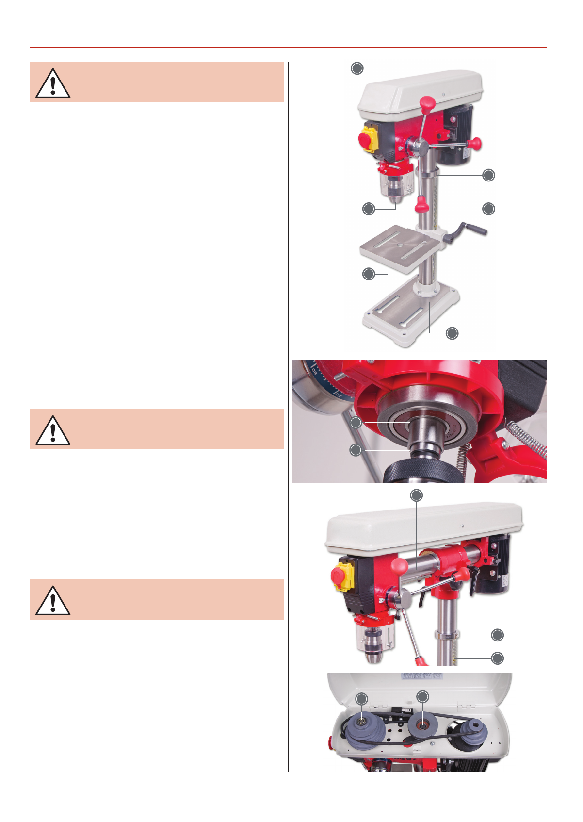
MAINTENANCE
WARNING! DISCONNECT THE MACHINE FROM THE
MAINS SUPPLY BEFORE CONTINUING!
Cleaning
Excessive dust in the motor can cause heat to develop.
Every effort should be made to prevent foreign material
from entering the motor.
Where you may find accumulations of dust, dirt or waste,
a visual inspection should be made at frequent intervals.
Accumulations of dry dust can usually be blown out.
Caution: To avoid eye injury or adverse reaction to dust,
high pressure hoses should not be used especially in
poorly ventilated areas.
After cleaning apply a light coat of machine oil on the quill
and chuck.
If the machine is going to stand idle for any length of time, a
light coat of spray or machine oil over the column and table
will prevent rusting. Place a dust sheet over the drill.
Oil Points
Electric
WARNING! DO NOT USE THE MACHINE IF THE
POWER CABLE HAS BECOME DAMAGED
If any servicing (other than the cleaning above) becomes
necessary, the unit should be returned to Axminster Tool Centre
f
or repair by one of our qualified electricians. Contact our
customer sales department for further assisance on:
Call: 03332 406406
(+441297 33666)
Email: [email protected]
WARNING! DO NOT ATTEMPED TO REPAIR IT
YOURSELF CONTACT OUR TECHNICAL SALES TEAM
FOR ASSISTANCE!
Motor speed
The speed of the motor cannot be regulated or changed - no
adjustment is necessary.
20
Page 21
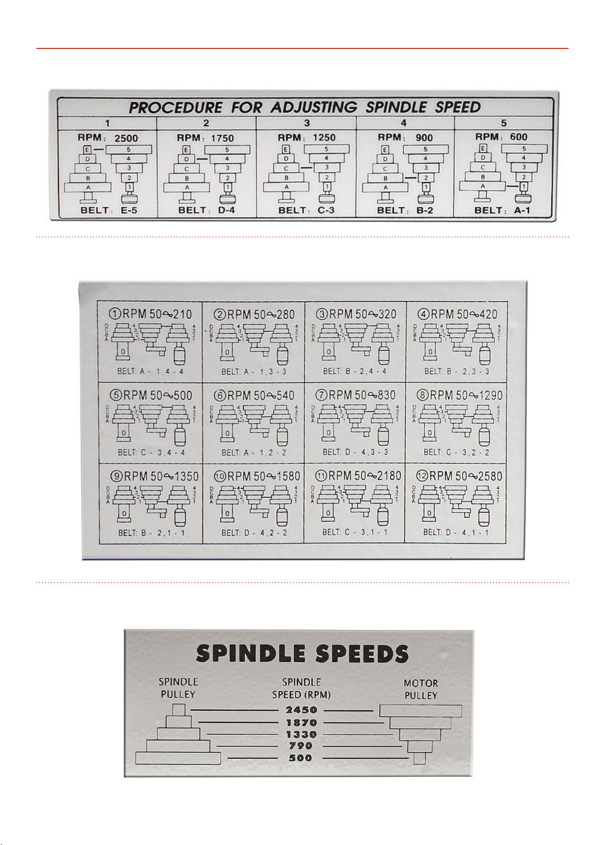
(5 Speed) 107690 AW285PD Bench Pillar Drill
(12 Speed) 107691 AW315PD Bench Pillar Drill
SPEED SELECT TABLES
(5 Speed) 107692AW220RD Bench Radial Pillar Drill 107693 AW680RD Floor Radial Pillar Drill
21
Page 22
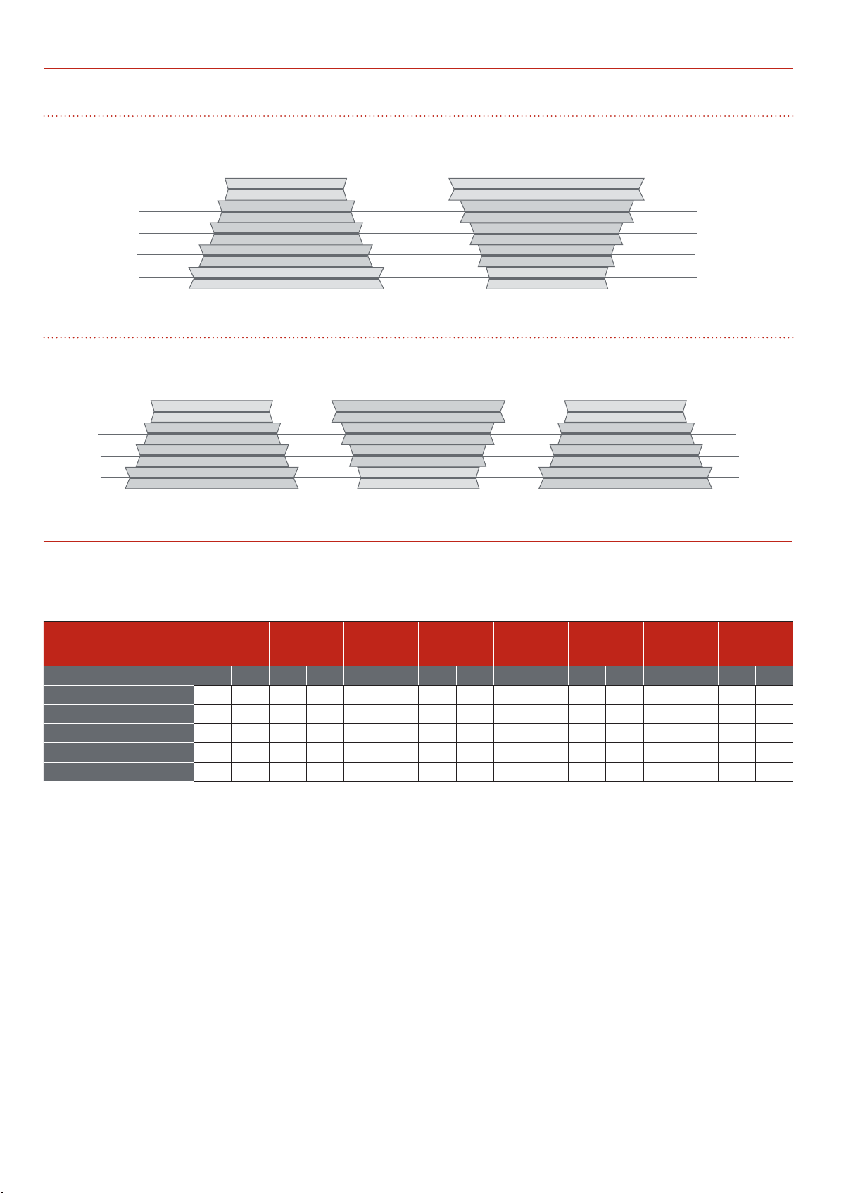
DRILL SPEED MATERIAL TABLE
5 Speed
Spindle Motor
E
D
C
B
A
12 Speed
Spindle MotorJockey Pulley
D
C
B
A
Recommended Drill Size per Material
5
4
3
2
1
4
3
2
1
Average Guide
Speed
50Hz inches mm inches mm inches mm inches mm inches mm inches mm inches mm inches mm
2450-2500-2580 rpm 5/16” 7.9 3/16 4.8 11/64 4.4 5/32 4.0 7/16 2.8 3/32 2.4 1/16 1.6 1/32 0.8
1580-1750-1870 rpm 3/8 9.5 1/4 6.4 7/32 5.6 3/16 4.8 1/8 3.2 3/32 2.4 1/16 1.6 3/64 1.2
1250-1290-1330 rpm 5/8 15.9 3/8 9.5 11/32 8.7 5/16 7.9 1/4 6.4 5/32 4.0 1/8 3.2 1/16 1.6
790-830-900 rpm 7/8 22.2 1/2 12.7 15/32 11.9 7/16 11.1 11/32 8.7 1/4 6.4 3/16 4.8 1/8 3.2
500-540-600 rpm 1
Wood
1
/4 31.8 3/4 19 11/16 17.5 5/8 15.9 1/2 12.7 3/8 9.5 5/16 7.9 1/4 6.4
Zinc
Diecast
Aluminium
or Brass
Plastic
Cast Iron
and Bronze
Steel
Mild and
Malleable
Steel Cast
and
Carbon
Steel
Stanless and
Too l
22
Page 23

TROUBLESHOOTING
TROUBLE PROBABLE CAUSE REMEDY
Noisy Operation
Drill bit burns
Drill bit leads off hole not round
Wood splinters on underside
1. Incorrect belt tension
2. Dry spindle
3. Loose spindle pulley
4. Loose motor pulley
1. Incorrect speed
2. Chips not coming out of hole
3.
Dull drill bit
4. Feeding too slow
5. Not lubricated
1. Hard grain in wood or lengths of
cutting tips and/or angles not equal
2. Bent drill bit
1. No “back-up material” under
workpiece
1. Adjust the tension
2. Lubricate spindle
3. Checking tightness of
retaining nut on pulley,
and tighten if necessary
Tighten set screws in pulleys
4.
1. Change speed
2. Retract drill bit frequently
to clear chips
3. Resharpen drill bit
4. Feed fast enough-allow drill
bit to cut.
5. Lubricate drill bit
1.
Resharpen drill bit correctly
2. Replace drill bit
1. Use “back-up material”
Workpiece torn loose from hand
Drill bit binds in workpiece
Excessive drill bit runout or wobble
Quill returns too slow or too fast
Chuck will not stay attached to
spindle it falls off when trying to
install it
1. Not supported or clamped
properly
1. Workpiece pinching drill bit
or excessive feed pressure
2. Improper belt tension
1. Bent drill bit
2. Worn spindle bearings
3. Drill bit not properly
installed in chuck
4. Chuck not properly installed
1. Spring has improper tension 1. Adjust spring tension
1. Dirty, grease or oil on the tapered
inside surface of chuck or on the
spindles tapered surface
Support workpiece or clamp it
1.
1.
Support workpiece or clamp it
2. Adjust tension
1. Use a straight drill bit
2. Replace bearings
3.
Install drill bit properly
4. Install chuck properly
1. Make sure all surfaces are free of dust
and grease
23
Page 24
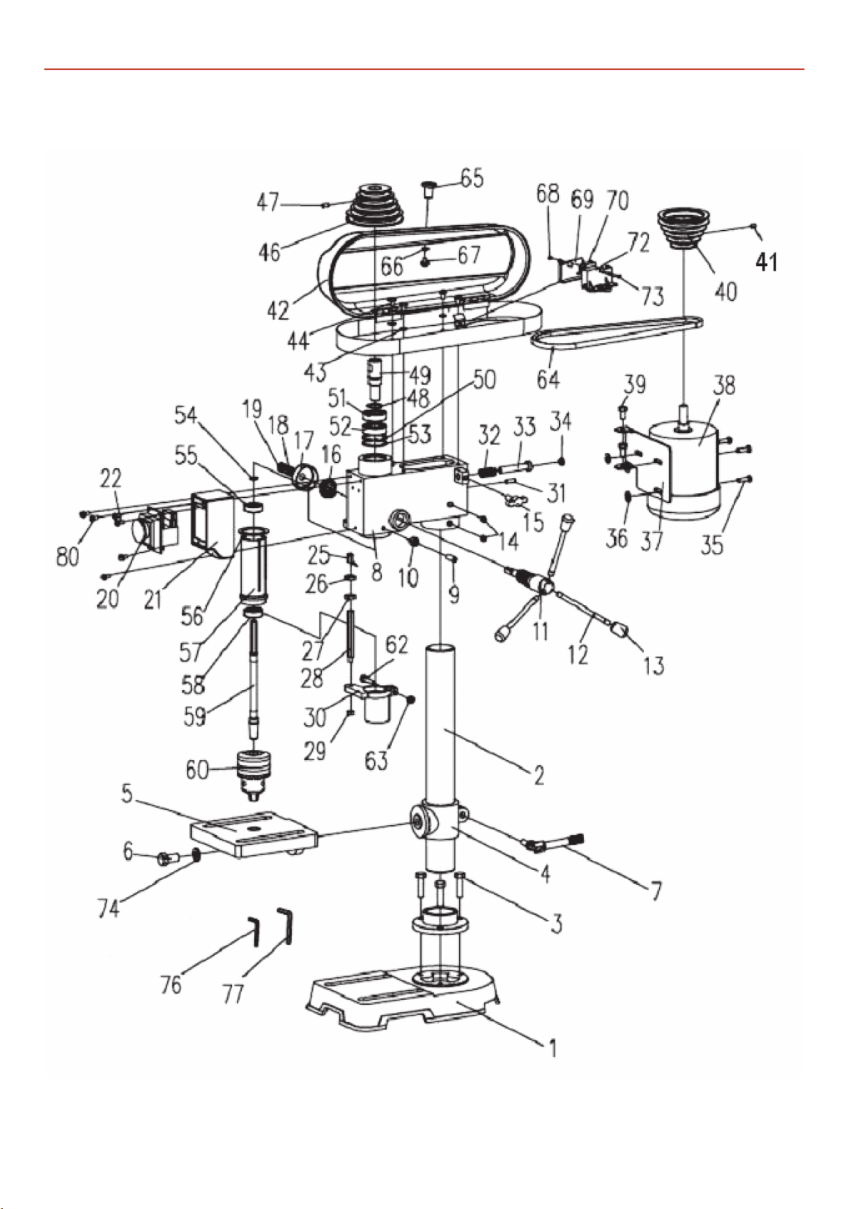
EXPLODED DIAGRAMS/LISTS
AW285PD Bench Pillar Drill (ZQJ4113A)
24
Page 25

AW285PD Bench Pillar Drill (ZQJ4113A)
EXPLODED DIAGRAMS/LISTS
NO DESCRIPTION QTY
1 BASE 1
2 COLUMN 1
3 BOLT M8X20 3
4 TABLE BRACKET 1
5 SQUARE TABLE 1
6 BOLT M12x25 1
7 CLAMPING LEVER 1
8 BODY 1
9 SCREW M6x18 1
10 NUT M6 1
11 FEED SHAFT 1
12 HANDLE BAR 3
13 KNOB 3
14 HEADLESS SET SCREW 2
15 SHIFTER BAR 1
16 SPRING SEAT 1
17 SPRING CAP 1
18 NUT 1
19 NUT 1
20 SWITCH 1
21 SWITCH BOX 1
22 SCREW 3
25 POINTER 1
26 NUT 1
27 NUT 1
28 LIMIT BOLT 1
29 NUT 1
30 CHUCK GUARD 1
31 PINS 1
32 SPRING 1
33 ADJUSTING BAR 1
34 RUBBER PAD 1
35 BOLT 3
36 WASHER 3
37 MOTOR MOUNTING PLATE 1
38 MOTOR 1
39 BOLT M8x16 2
40 MOTOR PULLEY 1
41 HEADLESS SET SCREW 1
42 PULLEY COVER 1
43 WASHER 4
44 SCREW M6X10 4
46 SPINDLE PULLEY 1
47 HEADLESS SET SCREW 1
48 RETAIN RING 1
49 INTERNAL SPLINE SLEEVE 1
50 RETAIN RING 1
51 BALL BEARING 6203-2RZ/Z1 1
52 BALL BEARING 6203-2RZ/Z1 1
53 RETAIN RING 1
54 RETAIN RING 1
55 BALL BEARING 6201-2RZ-Z1 1
56 WASHER 1
57 SPINDLE SLEEVE 1
58 BALL BEARING 6201-2RZ-Z1 1
59 SPINDLE 1
60 DRILL CHUCK 1
62 BOLT M6X25 1
63 NUT 1
64 V-BELT 1
65 HANDLE 1
66 WASHER 1
67 SCREW 1
68 NUT M3 OPTIONAL 2
69 PLATE OPTIONAL 1
70 MICRO SWITCH OPTIONAL 1
72 SUPPORT PLATE OPTIONAL 1
73 SCREW M3X18 OPTIONAL 2
74 SPRING WASHER 1
1
76 HEX KEY 3 mm 1
77 HEX KEY 4 mm 1
80 SCREW M4x10 4
25
Page 26
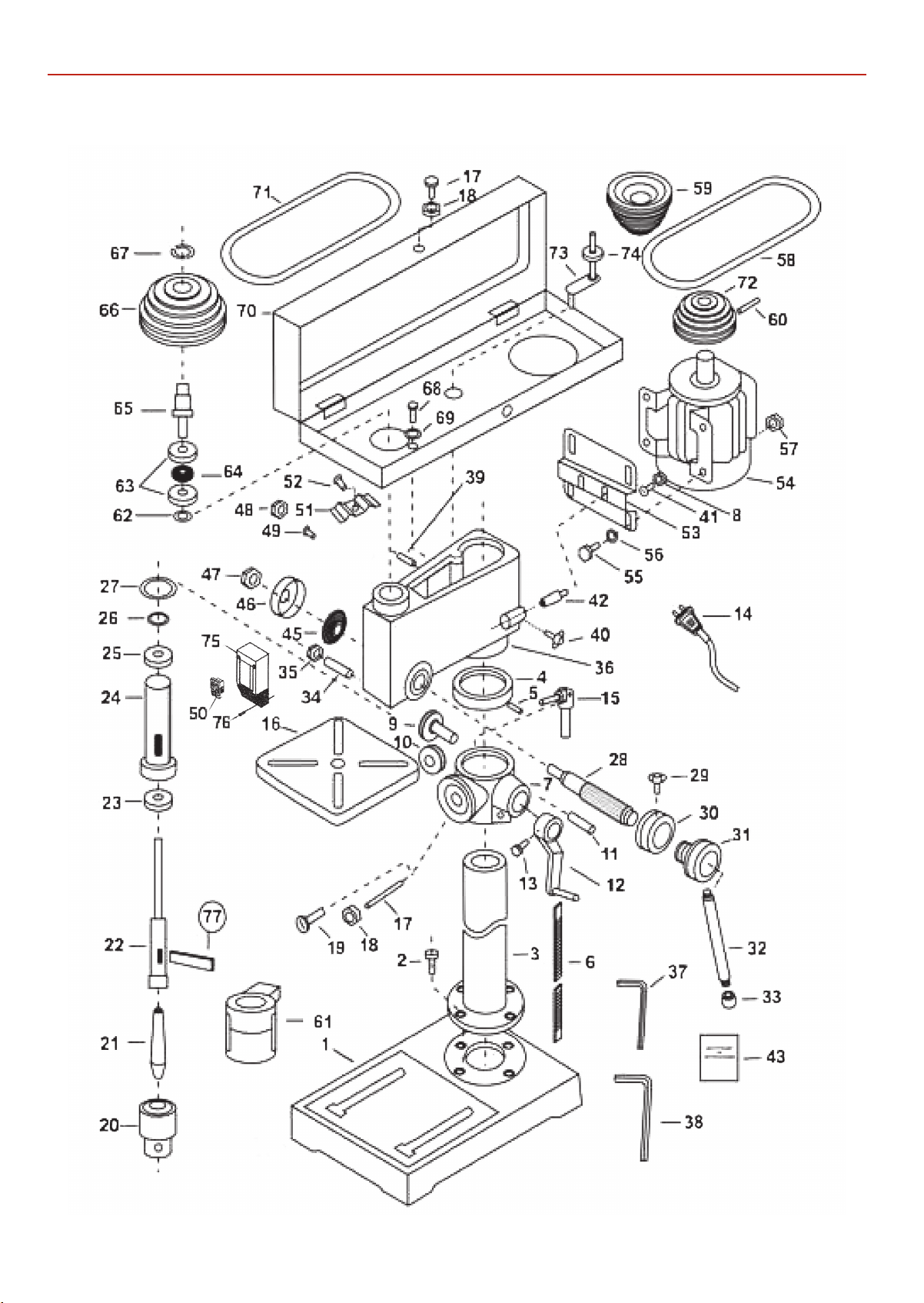
EXPLODED DIAGRAMS/LISTS
AW315PD Bench Pillar Drill (ZQJ4116Q)
26
Page 27
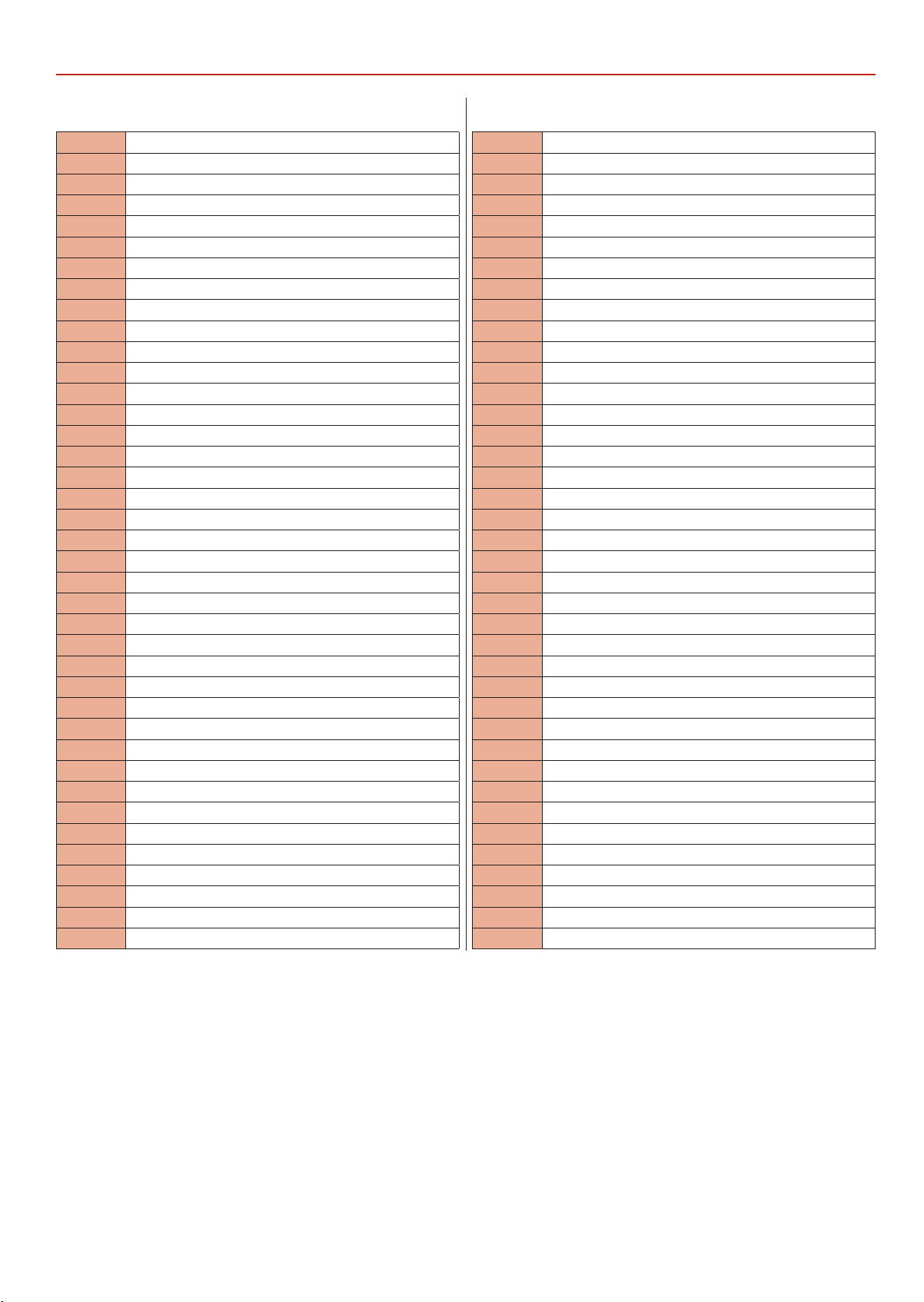
AW315PD Bench Pillar Drill (ZQJ4116Q)
EXPLODED DIAGRAMS/LISTS
NO DESCRIPTION
1 BASE
2 BOLT
3 COLUMN
4 RACK RING
5 HEADLESS SET SCREW
6 RACK
7 MOUNTING ARM BRACKET
8 NUT
9 WORM GEAR
10 GEAR
11 SHAFT
12 HANDLE
13 SET BOLT
14 PLUG
15 CLAMP BOLT
16 TABLE
17 PIN
18 NUT
19 SET SCREW
20 CHUCK
21 ARBOR
22 SPINDLE
23 BALL BEARING
24 SPINDLE SLEEVE
25 BALL BEARING
26 RETAIN RING
27 RUBBER WASHER
28 FEED SHAFT
29 CLAMP BOLT
30 SCALE RING
31 HANDLE BODY
32 HANDLE
33 KNOB
34 HEADLESS SET SCREW
35 NUT
36 BODY
37 HEX. KEY
38 HEX. KEY
39 HEADLESS SET SCREW
40 SLIDE BAR BOLT
41 SCREW
42 SLIDE BAR
43 INSTRUCTION MANUAL
44 CHUCK KEY
45 SPRING
46 SPRING SEAT
47 NUT
48 PLASTIC JAM NUT
49 SCREW
50 SWITCH
51 WIRE CLAMP
52 SCREW
53 MOTOR MOUNTING PLATE
54 MOTOR
55 BOLT
56 WASHER
57 NUT
58 V-BELT
59 CENTRE PULLEY
60 HEADLESS SET SCREW
61 CHUCK GUARD
62 RETAIN RING
63 BALL BEARING
64 COLLAR
65 DRIVE SLEEVE
66 SPINDLE PULLEY
67 PULLEY NUT
68 SCREW
69 WASHER
70 PULLEY COVER
71 V-BELT
72 MOTOR PULLEY
73 CENTER SHAFT
74 BALL BEARING
75 SWITCH BOX
76 SCREW M5 X 12
77 WEDGE
27
Page 28
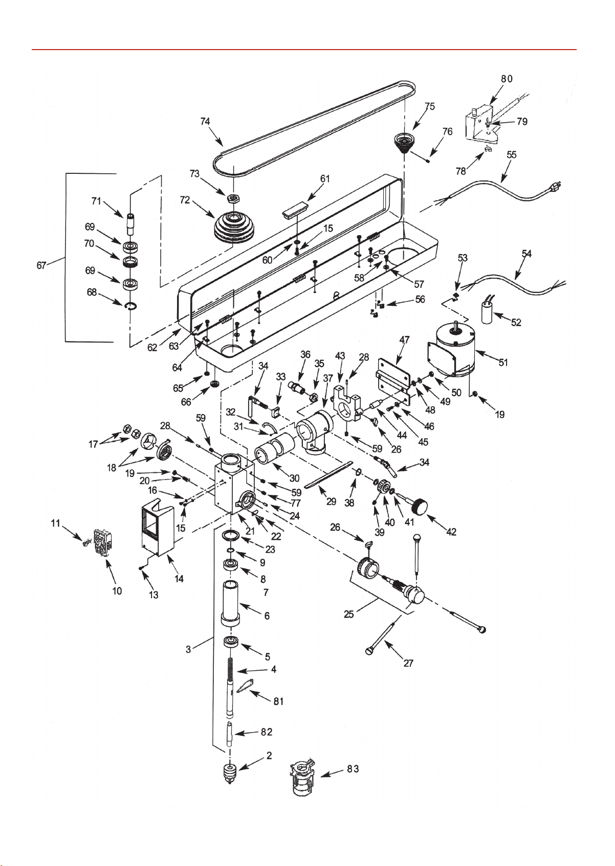
EXPLODED DIAGRAMS/LISTS
AW220RD Bench Radial Drill (ZQJ3116)
AW680RD Floor Radial Drill (ZQJ3116A)
28
Page 29
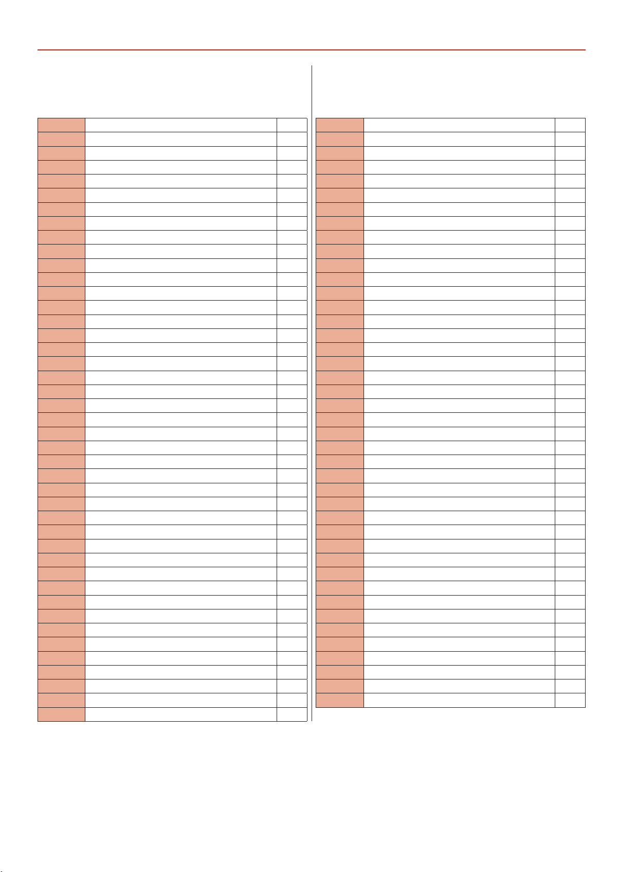
AW220RD Bench Radial Drill (ZQJ3116)
AW680RD Floor Radial Drill (ZQJ3116A)
EXPLODED DIAGRAMS/LISTS
NO DESCRIPTION QTY
2 CHUCK 1
3 LOWER SPINDLE ASSEMBLY 1
4 SPINDLE 1
5 6202LL BALL BEARING 1
6 QUILL 1
7 6201LL BALL BEARING 1
8 RETAINING RING 1
9 RUBBER BUMPER 1
10 SWITCH 1
11 THREADFORMING SCREW 2
13 PAN HEAD SCREW 4
14 COVER 1
15 PAN HEAD SCREW 3
16 5MM SERRATED WASHER 2
17 HEX NUT 2
18 CAP COVER AND SPRING 1
19 HEX NUT 5
20 CONE POINT SET SCREW 1
21 DRILL PRESS HEAD 1
22 POINTER 1
23 RIVET 1
24 SPRING PIN 1
25 QUILL FEED ASSEMBLY 1
(INCL. REF. NOS. 26 AND 27)
26 KNOB 3
27 HANDLE WITH GRIP 3
28 SPRING PIN 2
29 RADIAL RACK 1
30 RAM 1
31 PAN HEAD SCREW 2
32 SCALE 1
33 LOCKING SHOE 1
34 HANDLE 2
35 HEX NUT 1
36 GUIDE PIN ASSEMBLY 1
37 RAM BRACKET (MODE:ZQJ3116) 1
37 RAM BRACKET (MODE:ZQJ3116A) 1
38 RETAINING RING 1
39 SET SCREW 1
40 GEAR 1
41 SPACER 2
42 KNOB 1
43 BRACKET 1
44 TENSION ADJUSTMENT BAR 2
45 HEX HEAD BOLT 4
46 8MM FLAT WASHER 4
47 MOTOR MOUNT PLATE 1
48 10MM FLAT WASHER 2
49 10MM LOCK WASHER 2
50 HEX NUT 2
51 MOTOR (INCL. REF. NOS. 52-54) 1
52 CAPACITOR 1
53 STRAIN RELIEF 1
54 MOTOR CORD 1
55 LINE CORD 1
56 STRAIN RELIEF 2
57 6MM FLAT WASHER 4
58 PAN HEAD SCREW 4
59 SET SCREW 3
60 5MM FLAT WASHER 1
61 KNOB 1
62 PULLEY HOUSING 1
63 PAN HEAD SCREW 4
64 CORD CLAMP 4
65 HEX NUT 4
66 GROMMET 1
67 UPPER SPINDLE ASSEMBLY 1
(INCL. REF. NOS. 68-71)
68 RETAINING RING 1
69 6203LL BALL BEARING 2
70 SPACER 1
71 UPPER SPINDLE SLEEVE 1
72 SPINDLE PULLEY 1
73 PULLEY NUT 1
74 V-BELT 1
75 MOTOR PULLEY 1
76 SET SCREW 1
77 CONE POINT SET SCREW 1
78 NUT 1
79 SCREW 1
80 SWITCH 1
81 WEDGE 1
82 LIVE AXLE 1
83 GUARD 1
29
Continues Over....
Page 30
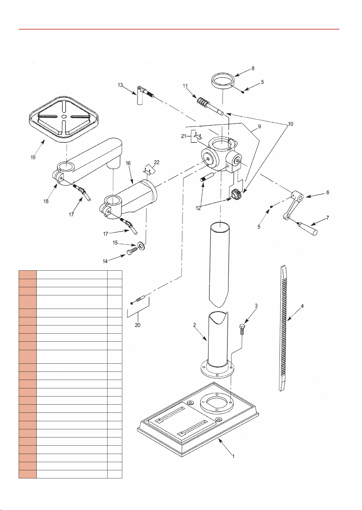
EXPLODED DIAGRAMS/LISTS
AW220RD Bench Radial Drill (ZQJ3116)
NO DESCRIPTION QTY
1 BASE 1
2 COLUMN ASSEMBLY 1
3 8-1.25 X 20MM SOCKET HEAD
BOLT
4 RACK 1
5 6-1.0 X 10MM SET SCREW 2
6 CRANK 1
7 HANDLE 1
8 RACK RETAINING RING 1
9 TABLE BRACKET ASSEMBLY (INCL.
REF. NOS. 12 AND 21)
10 WORM AND PINION GEAR SET 1
11 WORM GEAR 1
12 PINION GEAR AND SHAFT 1
13 LOCKING HANDLE 1
14 12-1.75 X 25MM HEX HEAD BOLT 1
15 12MM FLAT WASHER 1
16 ARM 1
17 LOCKING HANDLE 2
18 EXTENSION ARM 1
19 SQUARE TABLE 260 X 260MM 1
20 INDEX PIN AND NUT 1
21 6-1.0MM HEX NUT 1
22 SCALE WITH RIVETS 1
22 INDICATOR WITH RIVETS 1
4
1
30
Page 31
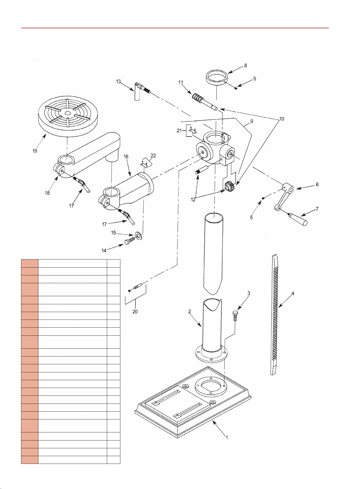
AW680RD Floor Radial Drill (ZQJ3116A)
EXPLODED DIAGRAMS/LISTS
NO DESCRIPTION QT Y
1 BASE 1
2 COLUMN ASSEMBLY 1
3 8-1.25 X 20MM SOCKET HEAD
BOLT
4 RACK 1
5 6-1.0 X 10MM SET SCREW 2
6 CRANK 1
7 HANDLE 1
8 RACK RETAINING RING 1
9 TABLE BRACKET ASSEMBLY (INCL.
REF. NOS. 12 AND 21)
10 WORM AND PINION GEAR SET 1
11 WORM GEAR 1
12 PINION GEAR AND SHAFT 1
13 LOCKING HANDLE 1
14 12-1.75 X 25MM HEX HEAD BOLT 1
15 12MM FLAT WASHER 1
16 ARM 1
17 LOCKING HANDLE 2
18 EXTENSION ARM 1
19 ROUND TABLE 310MM DIAM-
ETER
20 INDEX PIN AND NUT 1
21 6-1.0MM HEX NUT 1
22 SCALE WITH RIVETS 1
22 INDICATOR WITH RIVETS 1
4
1
1
31
Page 32
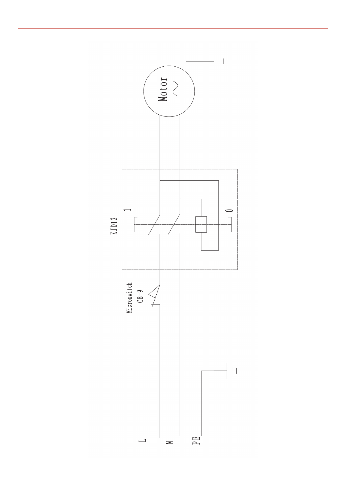
WIRING DIAGRAM
32
Page 33

NOTES
33
Page 34
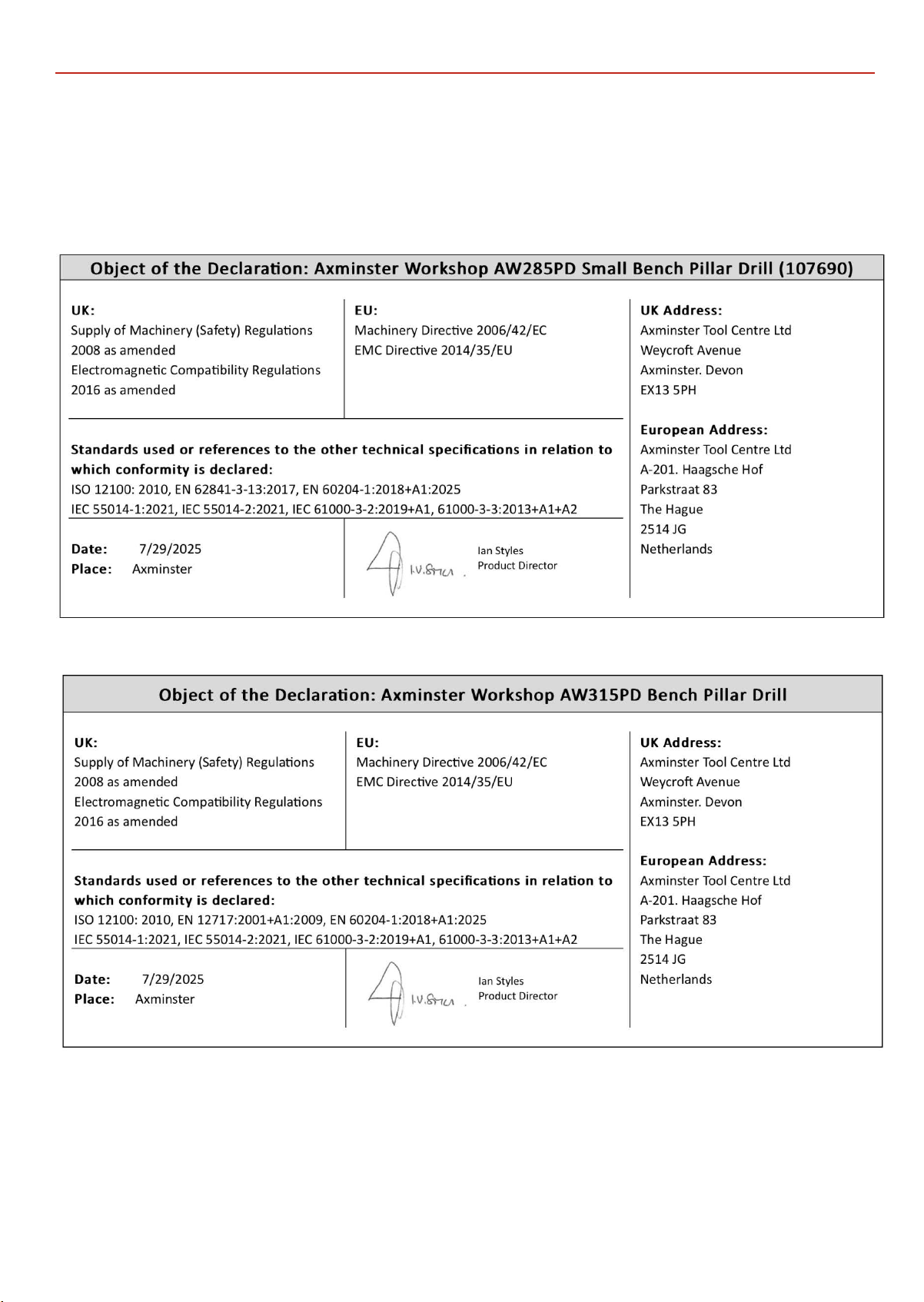
/UKCA DECLARATION OF CONFORMITY
EU
34
Page 35
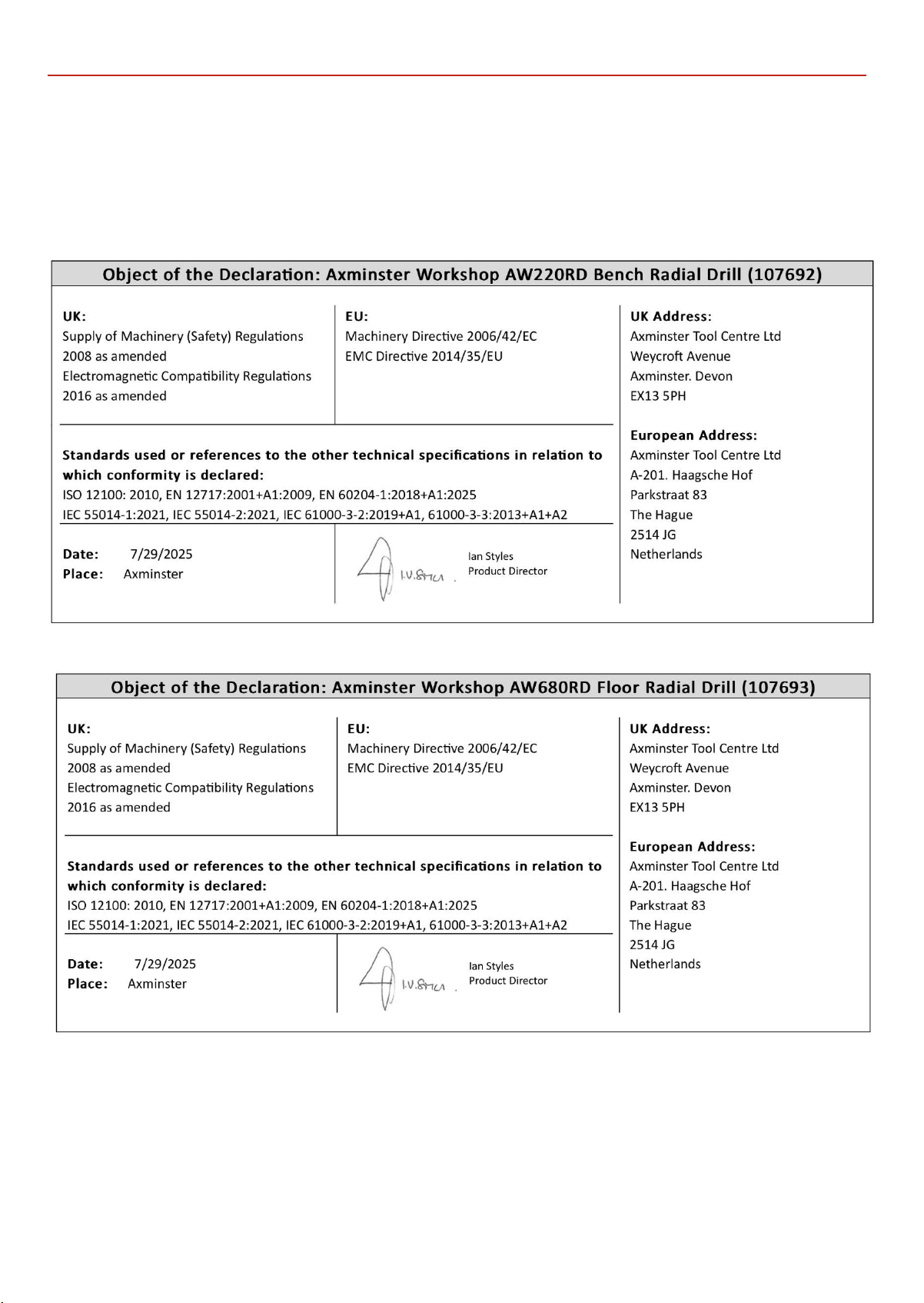
EU/UKCA DECLARATION OF CONFORMITY
35
Page 36

Axminster Tools, Axminster Devon EX13 5PH
axminstertools.com
The packaging is suitable for recycling.
Please dispose of it in a responsible manner.
Do not dispose of electric tools together with household waste material.
By law they must be collected and recycled separately.
EU Countries Only
 Loading...