

Page 1
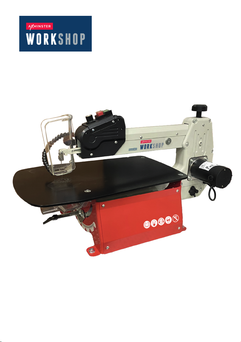
AW457S S
Scroll Saw
Code 111916
Original Instructions
AT20/12/2024
BOOK VERSION: 1
Page 2
Read all safety warnings and all instructions. Failure to follow the warnings
and instructions may result in electric shock, fire and/or serious injury.
WORK AREA SAFETY
1. Keep work area clean and well lit. Cluttered or dark areas invite accidents.
2. Do not operate power tools in explosive atmospheres, such as in the
presence of flammable liquids, gases or dust. Power tools create sparks which
may ignite the dust or fumes.
3. Keep children and bystanders away while operating a power tool. Distractions
can cause you to lose control.
ELECTRICAL SAFETY
1. Power tool plugs must match the outlet. Never modify the plug in any way.
Do not use any adapter plugs with earthed (grounded) power tools. Unmodified
plugs and matching outlets will reduce risk of electric shock.
2. Avoid body contact with earthed or grounded surfaces such as pipes, radiators,
ranges and refrigerators. There is an increased risk of electric shock if your body
is earthed or grounded.
3. Do not expose power tools to rain or wet conditions. Water entering a power
tool will increase the risk of electric shock.
4. Do not abuse the cord. Never use the cord for carrying, pulling or unplugging
the power tool. Keep cord away from heat, oil, sharp edges or moving parts.
Damaged or entangled cords increase the risk of electric shock.
5. When operating a power tool outdoors, use an extension cord suitable for
outdoor use. Use of a cord suitable for outdoor use reduces the risk of electric
shock.
6. If operating a power tool in a damp location is unavoidable, use a ground fault
circuit interrupter (GFCI) protected supply. Use of a GFCI reduces the risk of
electric shock.
PERSONAL SAFETY
1. Stay alert, watch what you are doing and use common sense when operating
a power tool. Do not use a power tool while you are tired or under the influence
of drugs, alcohol or medication. A moment of inattention while operating power
tools may result in serious personal injury.
2. Use personal protective equipment. Always wear eye protection. Protective
equipment such as a respiratory mask, non-skid safety shoes and hearing
protection used for appropriate conditions will reduce the risk of personal injury.
3. Prevent unintentional starting. Ensure the switch is in the off-position before
connecting to power source and/or battery pack, picking up or carrying the tool.
Carrying power tools with your finger on the switch or energizing power tools
that have the switch on invites accidents.
4. Remove any adjusting key or wrench before turning the power tool on. A
WARNING
!
3
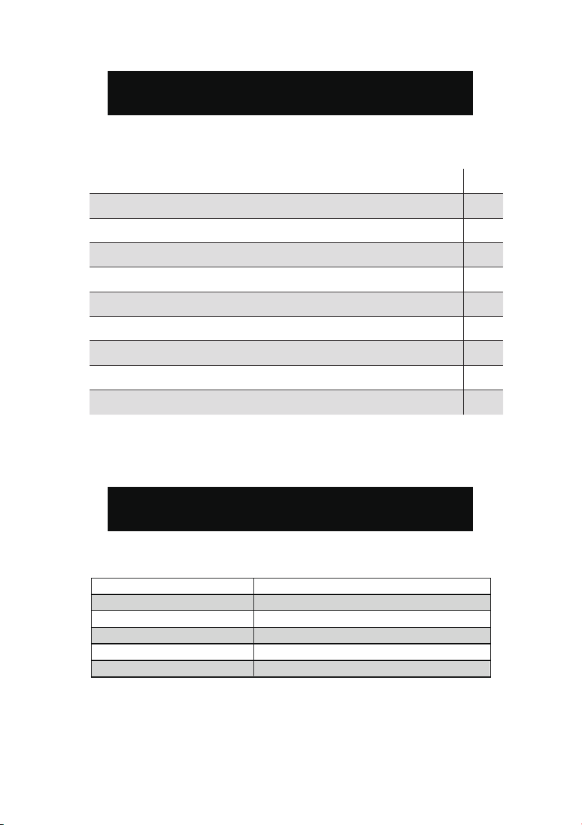
TABLE OF CONTENTS
TABLE OF CONTENTS
Specifications 2
Specifications 2
Safety Guidelines 3
Safety guidelines 3
Key Parts Diagram 7
Key parts diagram
Attachment Parts Diagram 8
Attachment parts diagram
Assembly/Operating 9
Assembly/Operating
Maintenance 12
Maintenance
Troubleshooting 14
Troubleshooting
Exploded View 15
Exploded view
Parts List 16
Parts list
Conformity certificates 17
SPECIFICATIONS
7
8
9
12
14
15
16
SPECIFICATIONS
Input 230-240V/50Hz
No Load Speed
Table Size
Table tilting
Max cutting size
Max cutting depth
550-1550 RPM
540x350mm
Left 0°- 45°,Right 0°- 45°
457mm
50mm at 0°, 20mm at 45°
2
Page 3

WARNING
!
Read all safety warnings and all instructions. Failure to follow the warnings
and instructions may result in electric shock, fire and/or serious injury.
WORK AREA SAFETY
1. Keep work area clean and well lit. Cluttered or dark areas invite accidents.
2. Do not operate power tools in explosive atmospheres, such as in the
presence of flammable liquids, gases or dust. Power tools create sparks which
may ignite the dust or fumes.
3. Keep children and bystanders away while operating a power tool. Distractions
can cause you to lose control.
ELECTRICAL SAFETY
1. Power tool plugs must match the outlet. Never modify the plug in any way.
Do not use any adapter plugs with earthed (grounded) power tools. Unmodified
plugs and matching outlets will reduce risk of electric shock.
2. Avoid body contact with earthed or grounded surfaces such as pipes, radiators,
ranges and refrigerators. There is an increased risk of electric shock if your body
is earthed or grounded.
3. Do not expose power tools to rain or wet conditions. Water entering a power
tool will increase the risk of electric shock.
4. Do not abuse the cord. Never use the cord for carrying, pulling or unplugging
the power tool. Keep cord away from heat, oil, sharp edges or moving parts.
Damaged or entangled cords increase the risk of electric shock.
5. When operating a power tool outdoors, use an extension cord suitable for
outdoor use. Use of a cord suitable for outdoor use reduces the risk of electric
shock.
6. If operating a power tool in a damp location is unavoidable, use a ground fault
circuit interrupter (GFCI) protected supply. Use of a GFCI reduces the risk of
electric shock.
PERSONAL SAFETY
1. Stay alert, watch what you are doing and use common sense when operating
a power tool. Do not use a power tool while you are tired or under the influence
of drugs, alcohol or medication. A moment of inattention while operating power
tools may result in serious personal injury.
2. Use personal protective equipment. Always wear eye protection. Protective
equipment such as a respiratory mask, non-skid safety shoes and hearing
protection used for appropriate conditions will reduce the risk of personal injury.
3. Prevent unintentional starting. Ensure the switch is in the off-position before
connecting to power source and/or battery pack, picking up or carrying the tool.
Carrying power tools with your finger on the switch or energizing power tools
that have the switch on invites accidents.
4. Remove any adjusting key or wrench before turning the power tool on. A
3
Page 4

wrench or a key left attached to a rotating part of the power tool may result in
• Lead from lead-based paints.
• Crystalline silica from bricks, cement, and other masonry products.
• Arsenic and chromium from chemically treated lumber.
Your risk from these exposures varies depending on how often you do this type
of work. To reduce your exposure to these chemicals, work in a well-ventilated
area with approved safety equipment such as dust masks specially designed to
filter out microscopic particles.
BEFORE OPERATION
1. Check for both proper assembly and proper alignment of moving parts.
2. Understand the proper use of the ON / OFF switch.
3. Know the condition of the scroll saw. If any part is missing, bent, or does not
operate properly, replace the component before attempting to operate the scroll
saw.
4. Determine the type of work you are going to be doing. Properly protect your
body including your eyes, hands, face, and ears.
5. To avoid injury caused by pieces thrown from accessories, use only
recommended accessories designed for this saw. Follow the instructions supplied
with the accessory. The use of improper accessories may cause
risk of injury.
6. To avoid contact with rotating equipment:
- Do not put your fingers in a position where they risk contacting the blade if the
workpiece unexpectedly shifts or your hand unexpectedly slips.
- Do not cut a workpiece too small to be held safely.
- Do not reach under the scroll saw table when the motor is running.
- Do not wear loose clothing or jewelry. Roll long sleeves above the elbow. Tie
back long hair.
7. To avoid injury from accidental startups of the scroll saw:
- Make sure to turn OFF the switch and unplug the power cord from the electric
outlet before changing the blade, performing maintenance or making adjustments.
- Make sure the switch is OFF before plugging in the power cord to an electric outlet.
8. To avoid injury from a fire hazard, do not operate the scroll saw near flammable
liquids, vapors or gases.
9. To avoid back injury:
- Obtain help when raising the scroll saw more than 10 inches (25.4 cm). Bend
your knees when lifting the scroll saw.
- Carry the scroll saw by its base. Do not move the scroll saw by pulling on the
power cord. Pulling on the power cord could cause damage to the insulation or
the wire connections resulting in electric shock or fire.
5
SCROLL SAW SAFETY
1. To avoid injury from unexpected saw movement:
- Use the scroll saw on a firm level surface with adequate space for handling
and supporting the workpiece.
- Be sure the scroll saw cannot move when operated. Secure the scroll saw to a
workbench or table with wood screws or bolts, washers and nuts.
personal injury.
5. Do not overreach. Keep proper footing and balance at all times. This enables
better control of the power tool in unexpected situations.
6. Dress properly. Do not wear loose clothing or jewelry. Keep your hair and
clothing away from moving parts. Loose clothes, jewelry or long hair can be
caughtin moving parts.
7. If devices are provided for the connection of dust extraction and collection
facilities, ensure these are connected and properly used. Use of dust collection
can reduce dust-related hazards.
POWER TOOL USE AND CARE
1. Do not force the power tool. Use the correct power tool for your application.
The correct power tool will do the job better and safer at the rate for which it was
designed.
2. Do not use the power tool if the switch does not turn it on and off. Any power
tool that cannot be controlled with the switch is dangerous and must be repaired.
3. Disconnect the plug from the power source and/or the battery pack from the
power tool before making any adjustments, changing accessories, or storing
power tools. Such preventive safety measures reduce the risk of starting the
power tool accidentally.
4. Store idle power tools out of the reach of children and do not allow persons
unfamiliar with the power tool or these instructions to operate the power tool.
Power tools are dangerous in the hands of untrained users.
5. Maintain power tools. Check for misalignment or binding of moving parts,
breakage of parts and any other condition that may affect the power tool’s
operation. If damaged, have the power tool repaired before use. Many accidents
are caused by poorly maintained power tools.
6. Keep cutting tools sharp and clean. Properly maintained cutting tools with
sharp cutting edges are less likely to bind and are easier to control.
7. Use the power tool, accessories and tool bits, etc. in accordance with these
instructions, taking into account the working conditions and the work to be
performed. Use of the power tool for operations different from those intended
could result in a hazardous situation.
8. Use clamps to secure your workpiece to a stable surface. Holding a workpiece
by hand or using your body to support it may lead to loss of control.
9. KEEP GUARDS IN PLACE and in working order.
SERVICE
1. Have your power tool serviced by a qualified repair person using only identical
replacement parts. This will ensure that the safety of the power tool is maintained.
CALIFORNIA PROPOSITION 65 WARNING
Some dust created by power sanding, sawing, grinding, drilling, and other
construction activities may contain chemicals, including lead, known to the State
of California to cause cancer, birth defects, or other reproductive harm. Wash
hands after handling. Some examples of these chemicals are:
4
Page 5

• Lead from lead-based paints.
• Crystalline silica from bricks, cement, and other masonry products.
• Arsenic and chromium from chemically treated lumber.
Your risk from these exposures varies depending on how often you do this type
of work. To reduce your exposure to these chemicals, work in a well-ventilated
area with approved safety equipment such as dust masks specially designed to
filter out microscopic particles.
BEFORE OPERATION
1. Check for both proper assembly and proper alignment of moving parts.
2. Understand the proper use of the ON / OFF switch.
3. Know the condition of the scroll saw. If any part is missing, bent, or does not
operate properly, replace the component before attempting to operate the scroll
saw.
4. Determine the type of work you are going to be doing. Properly protect your
body including your eyes, hands, face, and ears.
5. To avoid injury caused by pieces thrown from accessories, use only
recommended accessories designed for this saw. Follow the instructions supplied
with the accessory. The use of improper accessories may cause
risk of injury.
6. To avoid contact with rotating equipment:
- Do not put your fingers in a position where they risk contacting the blade if the
workpiece unexpectedly shifts or your hand unexpectedly slips.
- Do not cut a workpiece too small to be held safely.
- Do not reach under the scroll saw table when the motor is running.
- Do not wear loose clothing or jewelry. Roll long sleeves above the elbow. Tie
back long hair.
7. To avoid injury from accidental startups of the scroll saw:
- Make sure to turn OFF the switch and unplug the power cord from the electric
outlet before changing the blade, performing maintenance or making adjustments.
- Make sure the switch is OFF before plugging in the power cord to an electric outlet.
8. To avoid injury from a fire hazard, do not operate the scroll saw near flammable
liquids, vapors or gases.
9. To avoid back injury:
- Obtain help when raising the scroll saw more than 10 inches (25.4 cm). Bend
your knees when lifting the scroll saw.
- Carry the scroll saw by its base. Do not move the scroll saw by pulling on the
power cord. Pulling on the power cord could cause damage to the insulation or
the wire connections resulting in electric shock or fire.
SCROLL SAW SAFETY
1. To avoid injury from unexpected saw movement:
- Use the scroll saw on a firm level surface with adequate space for handling
and supporting the workpiece.
- Be sure the scroll saw cannot move when operated. Secure the scroll saw to a
workbench or table with wood screws or bolts, washers and nuts.
5
Page 6

2. Before moving the scroll saw, unplug the power cord from the electrical outlet.
KEY PARTS DIAGRAM
1
2
3
5
4
10
6
7
8
9
7
No. Description Qty.
1 Blade tension knob
1
2
Power switch 1
3
Variable speed control knob 1
4
2
5
Sawdust blower
1
6
1
7
Hexagon socket fixing bolt
1
8
1
Work table
Wide saw blade
Motor
Table locking handle
9
1
1
Fender bracket
10
3. To avoid injury from kickback:
- Hold the workpiece firmly against the tabletop.
- Do not feed the workpiece too fast while cutting. Only feed the workpiece at
the rate the saw will cut.
- Install the blade with the teeth pointing downward.
- Do not start the saw with the workpiece pressing against the blade. Slowly feed
the workpiece into the moving blade.
- Use caution when cutting round or irregularly shaped workpieces. Round items
will roll and irregularly shaped workpieces can pinch the blade.
4. To avoid injury when operating the scroll saw:
- Obtain advice from a qualified person if you’re not thoroughly familiar with the
operation of scroll saws.
- Before starting the saw, make sure the blade tension is correct. Recheck and
adjust tension as needed.
- Make sure the table is locked into position before starting the saw.
- Do not use dull or bent blades.
- When cutting a large workpiece, make sure the material is supported at the
table height.
- Turn the saw OFF and unplug the power cord if the blade jams in the workpiece.
This condition is usually caused by sawdust clogging the line you are cutting.
Wedge open the workpiece and back out the blade after turning off and unplugging
the machine.
GROUNDING INSTRUCTIONS
In the event of a malfunction or breakdown, grounding provides the path of least
resistance for an electric current and reduces the risk of electric shock. This tool
is equipped with an electric cord that has an equipment grounding conductor and
a grounding plug. The plug MUST be plugged into a matching outlet that is properly
installed and grounded in accordance with ALL local codes and ordinances.
1. Do not modify the plug provided. If it will not fit the outlet, have the proper outlet
installed by a licensed electrician.
2. Improper connection of the equipment grounding conductor can result in electric
shock. The conductor with the green insulation (with or without yellow stripes) is the
equipment grounding conductor. If repair or replacement of the electric cord or plug is
necessary, DO NOT connect the equipment grounding conductorto a live terminal.
3. Check with a licensed electrician or service personnel if you do not completely
understand the grounding instructions or whether the tool is properly grounded.
4. Use only three-wire extension cords that have three-pronged plugs and outlets
that accept the tool’s plug. Repair or replace a damaged or worn cord immediately.
CAUTION! In all cases, make certain the outlet in question is properly grounded. If
you are not sure, have a licensed electrician check the outlet.
6
Page 7
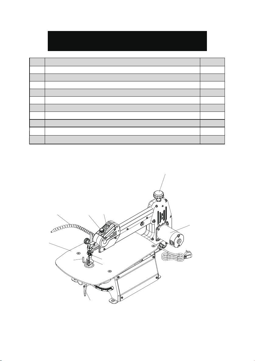
KEY PARTS DIAGRAM
No. Description Qty.
1 Blade tension knob
Power switch 1
2
Variable speed control knob 1
3
4
Hexagon socket fixing bolt
Fender bracket
5
6
Sawdust blower
Work table
7
Table locking handle
8
Motor
9
10
Wide saw blade
1
1
2
1
1
1
1
1
1
6
2
3
9
7
5
4
10
8
7
Page 8
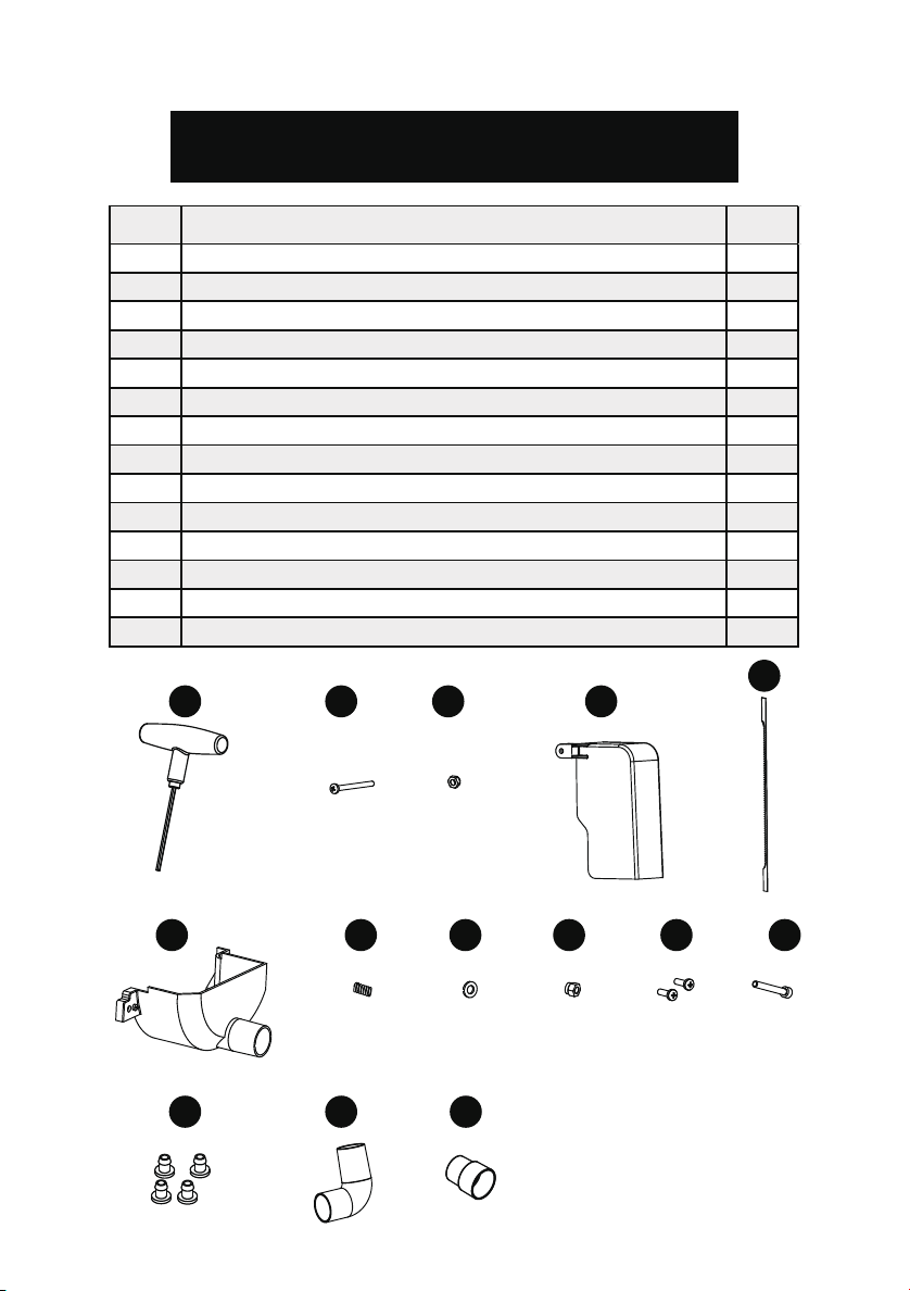
No. Description Qty.
SSA22
ASSEMBLY/OPERATING
The machine is designed to operate in closed rooms and must be placed stable on
firm and levelled s urfa ce . The machine can be bolted down if required.
If you notice any transport damage while unpacking, notify your supplier immediately.
Do not operate the machine!
Dispose of the packing in an environmentally friendly manner. Clean all rust protected
surfaces with a mild solvent.
WARNING
!
TO REDUCE RISK OF INJURY:
• When carrying the saw, hold it close to your body to avoid injury to your back. Bend
your knees when lifting the saw.
• Carry the saw by the base, table, housing, or motor. Do not carry the saw by the
power cord or upper arm.
• Secure the saw in a position where people cannot stand, sit, or walk behind it. Debris
thrown from the saw could injure people standing, sitting, or walking behind it.
Securethe saw on a firm, level surface where the saw cannot rock. Make sure there
is adequate room for handling and properly supporting the workpiece
INSTALLATION OF GUARDS
9
1
2
3
4
As shown in the photo, pass the Blade safety
guard (1) from the top through the Drop foot
pole (2) aligning the hole in the center, and
pass the Phillips screw M5X30 (3) through the
hole with the Locking nut (4) to secure it.
INSTALLATION OF RUBBER FOOT
Take the four rubber foot (1) and insert them
into the holes in the base.
1
ATTACHMENT PARTS DIAGRAM
1 T special spanner 1
2 Phillips screw M5X30 1
3 Locking nut 1
4 Blade safety guard 1
5 Blade without pin 1
6 Lower safety guard 1
7 Probe compression spring 1
8 Flat washer D5 1
9 Type I Non-metal insert hexagon lock nut -M5 1
10 Phillips screw M4X10 2
11 Hexagon flat round head screw M5X20 1
12 Rubber foot 4
13 Elbow 1
14 Dust port nozzle 1
5
1 2 3
4
6 7 8 9 10 11
12 13 14
8
Page 9
SSA22
ASSEMBLY/OPERATING
The machine is designed to operate in closed rooms and must be placed stable on
firm and levelled s urfa ce . The machine can be bolted down if required.
WARNING
!
If you notice any transport damage while unpacking, notify your supplier immediately.
Do not operate the machine!
Dispose of the packing in an environmentally friendly manner. Clean all rust protected
surfaces with a mild solvent.
TO REDUCE RISK OF INJURY:
• When carrying the saw, hold it close to your body to avoid injury to your back. Bend
your knees when lifting the saw.
• Carry the saw by the base, table, housing, or motor. Do not carry the saw by the
power cord or upper arm.
• Secure the saw in a position where people cannot stand, sit, or walk behind it. Debris
thrown from the saw could injure people standing, sitting, or walking behind it.
Securethe saw on a firm, level surface where the saw cannot rock. Make sure there
is adequate room for handling and properly supporting the workpiece
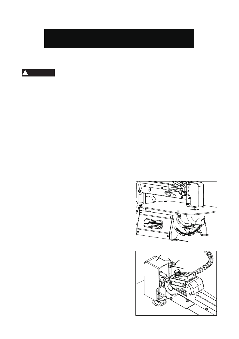
INSTALLATION OF RUBBER FOOT
Take the four rubber foot (1) and insert them
into the holes in the base.
INSTALLATION OF GUARDS
As shown in the photo, pass the Blade safety
guard (1) from the top through the Drop foot
pole (2) aligning the hole in the center, and
pass the Phillips screw M5X30 (3) through the
hole with the Locking nut (4) to secure it.
9
1
1
2
3
4
Page 10
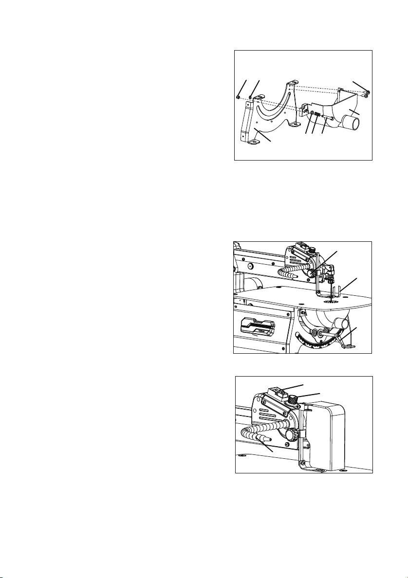
INSTALLATION OF LOWER GUARDS
1. Lay out desired design, or secure design to the workpiece.
2. Raise the blade guard foot by loosening the height adjustment knob.
3. Position the workpiece against the blade and place the blade guard foot just above
the top surface of the workpiece.
4. Secure the blade guard foot by tightening the height adjustment knob.
5. Remove the workpiece from the blade prior to turning the scroll saw ON.
6. Slowly feed the workpiece into the blade while holding the workpiece securely
against the table.
7. When cutting is complete, move trailing edge of the workpiece beyond the blade
guard foot. Turn the switch OFF.
FREEHAND CUTTING
To avoid injury from accidental start-ups, always turn the switch OFF and unplug the scroll
saw before moving the saw, replacing the blade, or making adjustments.
WARNING
!
11
1. Layout or secure design to workpiece.
2. Loosen the drop foot rod handle (2), move the drop foot (1) to the highest position,
and retighten the knob.
3. Tilt the table to the desired angle by turning the level lock handle (3).
ANGLE CUTTING (BEVELING)
1
2
3
TIP: The table has positive stops at 0, 22.5, 30,
and 45 degrees.
4. Tighten the table locking handle (3).
5. Loosen the blade guard screw, and tilt the
drop foot (1) to the same angle as the table.
Retighten the blade guard screw.
6. Position the workpiece on the right side of
the blade. Lower the drop foot against the
surface by loosening the height adjustment
knob. Retighten.
7. Follow steps 5 to 7 under Freehand cutting.
INTERIOR CUTTING & FRETWORK
3
1
2
1. Lay out the design on the workpiece. Drill a
1/4” pilot hole in the workpiece.
2. Release the Tension knob(1) and remove
the blade from the upper blade clamp.
NOTE: If using a pinless saw blade, loosen
the hex socket screw with cylindrical head (3)
and remove the blade from the upper blade.
1. Pass hexagon flat round head screw M5X20
(1) through the holes on the left side of probe
compression spring (2), flat washer D5 (3) and
lower safety guard (4) one at a time and fix
lower safety guard (4) to the attach Lower
safety guard (4) to plate (5) and lock with type I
Non-metal insert hexagon lock nut -M5 (6),
Attach (8) to the plate (5) as shown..
2. Insert phillips screw M4X10 (7) through the
hole on the right side of the plate (5) and
tighten.
Warning: When using the machine,the lower guard must be installed and bolted in
place. The magnet has a certain adsorption capacity,but only auxiliary functions. When
using the machine ,it must be bolted according to above instructions to to prevent
injury.
8
6
7
4
1
2
3
5
ALIGN THE BEVEL INDICATOR
The bevel indicator has been adjusted at the
factory, but should be rechecked prior to use for
best operation.
1. Loosen the drop foot rod handle (1) and move
the drop foot (2) all the way up.
2. Check if the pointer is on the 0 scale. If not,
turn the table locking handle (3) bevel the
upper arm until it is approximately at a right
angle to the blade.
ADJUSTING THE DUST BLOWER
For best results, the Pipe (3) should be adjusted
to direct air at both the blade and the workpiece.
POWER SWITCH & SPEED CONTROL
KNOB
1. To turn the saw on, flip the I/O switch (1)
to I. When first starting the saw, it is best to move the speed control knob (2) to the
middle speed position.
2. Turning the control knob. Turning it towards H increases speed; turning it towards L
reduces speed.
3. To turn the saw off, flip the I/O switch back to O.
10
1
3
1
2
3
2
Page 11
WARNING!
To avoid injury from accidental start-ups, always turn the switch OFF and unplug the scroll
saw before moving the saw, replacing the blade, or making adjustments.
FREEHAND CUTTING
1. Lay out desired design, or secure design to the workpiece.
2. Raise the blade guard foot by loosening the height adjustment knob.
3. Position the workpiece against the blade and place the blade guard foot just above
the top surface of the workpiece.
4. Secure the blade guard foot by tightening the height adjustment knob.
5. Remove the workpiece from the blade prior to turning the scroll saw ON.
6. Slowly feed the workpiece into the blade while holding the workpiece securely
against the table.
7. When cutting is complete, move trailing edge of the workpiece beyond the blade
guard foot. Turn the switch OFF.
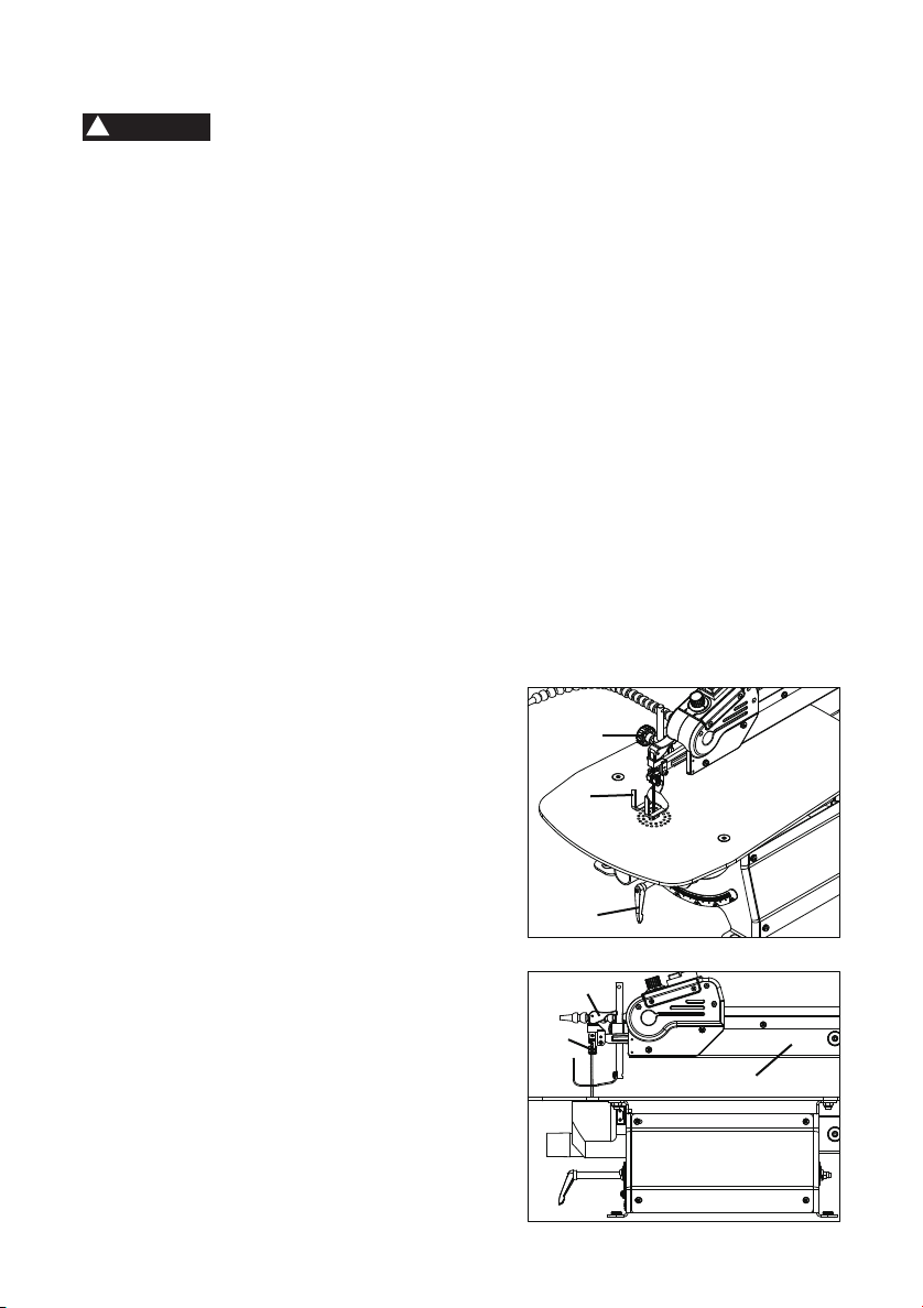
ANGLE CUTTING (BEVELING)
1. Layout or secure design to workpiece.
2. Loosen the drop foot rod handle (2), move the drop foot (1) to the highest position,
and retighten the knob.
3. Tilt the table to the desired angle by turning the level lock handle (3).
TIP: The table has positive stops at 0, 22.5, 30,
and 45 degrees.
4. Tighten the table locking handle (3).
5. Loosen the blade guard screw, and tilt the
drop foot (1) to the same angle as the table.
Retighten the blade guard screw.
6. Position the workpiece on the right side of
the blade. Lower the drop foot against the
surface by loosening the height adjustment
knob. Retighten.
7. Follow steps 5 to 7 under Freehand cutting.
2
1
3
1
INTERIOR CUTTING & FRETWORK
1. Lay out the design on the workpiece. Drill a
1/4” pilot hole in the workpiece.
2. Release the Tension knob(1) and remove
the blade from the upper blade clamp.
NOTE: If using a pinless saw blade, loosen
the hex socket screw with cylindrical head (3)
and remove the blade from the upper blade.
11
3
2
Page 12
3. Gently lift the upper arm (2) of the saw.
13
CARBON BRUSH REPLACEMENT
1
1. Clean your saw after each use. Wipe it down with a soft cloth. Clean any accumulated
sawdust out of the base. Use low-pressure compressed air (not to exceed 25 PSI) to
blow any sawdust out of the blade holders, blade bevel rails, etc.
2. If desired, apply a light coat of dry lubricant (such as PTFE) to the inside of the blade
bevel rails. This will help the table bevel smoothly.
3. The motor bearings, interior bearings, and table bevel rail bearings are all sealed and
require no additional lubrication.
GENERAL MAINTENANCE
19/32"
or less
The wear on the carbon brushes depends on how
frequently and how heavily the tool is used. To
maintain maximum efficiency of the motor, we
recommend inspecting the two carbon brushes
every 60 hours of operation or when the tool stops
working.
1. Unplug the saw. To access the carbon
brushes, remove the carbon brush cover (1)
with a flat-head screwdriver (not included).
2. Carefully remove the old carbon brush-
es.Keep track of which orientation the old
carbon brushes were in to prevent unneces-
sary wear if they will be reinstalled.
3. Measure the length of the brushes. Install the
new set of carbon brushes if either carbon
brush length is worn down to 19/32” or less.
Reinstall the old carbon brushes (in their
original orientation) if your brushes are not
worn down to 19/32” or less. Both carbon
brushes should be replaced at the same time.
4. Replace the carbon brush cover.
4. Place the workpiece on the saw table, threading the blade through the hole in the
workpiece.
5. Lower the upper arm.
6. Secure the blade in the upper blade clamp, as directed in “ Replace the saw blade ”
(see page 13)
7. Follow steps 4 - 7 under “Freehand cutting” .
8. When finished making the interior cuts, turn the scroll saw OFF and unplug it.
Relieve blade tension and remove the blade from the upper blade clamp. Raise the
upper arm and remove the workpiece. Lower the upper arm and lock it in place.
WARNING
!
Make sure the saw is turned OFF and unplugged before making any adjustments to
the blade.
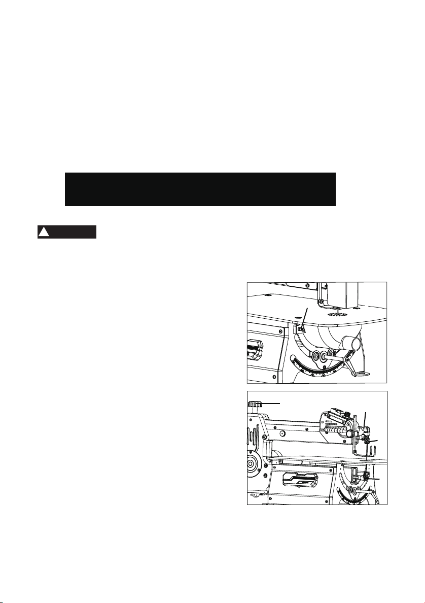
REPLACE THE SAW BLADE
1.Loosen the hexagon flat round head screw(1)
and then open the dust cover.
2. Release the tension knob(2) upwards then
loosen the bottom hexagon socket fixing bolt
(3). Remove the blade.
NOTE: When using a pinless saw blade you will
need to remove the blade by first loosening hex
socket screw with cylindrical head(4), loosen
the bottom hexagon socket fixing bolt (3).
3. With the blade’s teeth facing toward you and
pointing down, thread the new blade through
the table slot so that its bottom rests in the
bottom clamp.
5. Tighten the bottom hexagon socket fixing bolt
(3). This locks the blade in place.
6. Insert the top of the blade into the top clamp.
7. Lock the tension knob (2) downward to raise
the saw blade.
NOTE: When using pinless saw blades, tighten
the hexagon socket fixing bolt (2) to Lock up.
8. Fine-tune the Blade tension knob(5).
MAINTENANCE
1
5
2
4
3
TIP: A properly-tensioned blade will make a high-C sound (C6, 1047 Hz) when
plucked with a finger.
12
Page 13
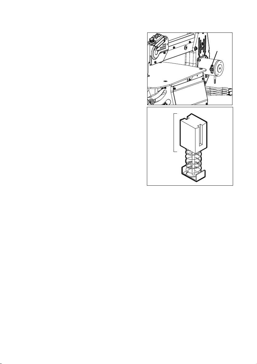
CARBON BRUSH REPLACEMENT
The wear on the carbon brushes depends on how
frequently and how heavily the tool is used. To
maintain maximum efficiency of the motor, we
recommend inspecting the two carbon brushes
every 60 hours of operation or when the tool stops
working.
1. Unplug the saw. To access the carbon
brushes, remove the carbon brush cover (1)
with a flat-head screwdriver (not included).
2. Carefully remove the old carbon brushes.Keep track of which orientation the old
carbon brushes were in to prevent unnecessary wear if they will be reinstalled.
3. Measure the length of the brushes. Install the
new set of carbon brushes if either carbon
brush length is worn down to 19/32” or less.
Reinstall the old carbon brushes (in their
original orientation) if your brushes are not
worn down to 19/32” or less. Both carbon
brushes should be replaced at the same time.
4. Replace the carbon brush cover.
1
19/32"
or less
GENERAL MAINTENANCE
1. Clean your saw after each use. Wipe it down with a soft cloth. Clean any accumulated
sawdust out of the base. Use low-pressure compressed air (not to exceed 25 PSI) to
blow any sawdust out of the blade holders, blade bevel rails, etc.
2. If desired, apply a light coat of dry lubricant (such as PTFE) to the inside of the blade
bevel rails. This will help the table bevel smoothly.
3. The motor bearings, interior bearings, and table bevel rail bearings are all sealed and
require no additional lubrication.
13
Page 14
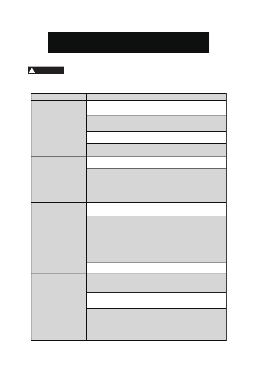
TROUBLESHOOTING GUIDE
EXPLODED VIEW
15
TROUBLE SHOOTING
WARNING
!
In the interests of operational safety, always switch off the saw and remove
the mains plug before carrying out maintenance work.
SYMPTOM PROBABLE CAUSE CORRECTIVE ACTION
Tension incorrectly set
Set the correct tension
Saw blades break
Motor does not
function
Vibration
The saw
NOTE:
vibrates slightly when
the motor is running in
normal operation
Saw blade s wings
out Holder not
aligned straight
Load to great
Incorrect saw blade variety Use the correct saw blades
Work piece not fed straight
Power extension cable faulty
Motor fault y
Saw
incorrectly inst alled
Unsuitable underlay
Motor control board failure Change a new control board
The work bench is not
screwed down or is on
the m otor
The mot or is not secured
Holders not aligned
14
Feed the work piece more
slowly
Avoid exerting side pressure
Change faulty cable
Call customer service . Do
not a ttemp t to repair the
motor yourself as this should
be carried out by trained
personnel.
Refer t o the instructions
in this manual
The heavier the work bench is
the less the vibration. A bench
made f rom plywood always
vibrate s more than one made
from solid wood.Select the
work bench best suited to your
working conditions .
Tighten t he locking lever
Securely screw the motor
in place
Loosen the screws with which
the holders are fastened to the
arm. Align the holders to that
they are perpendicular to each
other and retighten the screws.
Page 15
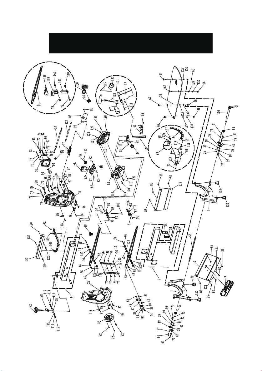
EXPLODED VIEW
15
Page 16

Cross recessed countersunk head tapping screw-ST2.9x8
Axminster Tool Centre Ltd
UK DECLARATION OF CONFORMITY
‘original’
Product model: Axminster Workshop AW457SS Scrollsaw
Name and address of the manufacturer: Axminster Tool Centre Ltd, Unit 10 Weycroft Avenue,
Axminster, Devon EX13 5PH, United Kingdom
This declaration of conformity is issued under the sole responsibility of the manufacturer.
Object of the declaration:
The object of the declaration described above is in conf ormity with the relevant GB legislation:
Supply of Machinery (Safety) Regulations 2008 as amended.
Electromagnetic Compatibility Regulations 2016 as amended.
References to the relevant harmonised standards used or references to the other technical
specifications in relation to which conformity is declared:
ISO 12100:2010 Safety of machinery - General principles for design - Risk assessment and
risk reduction
EN 50370-1:2005 Electromagnetic compatibility (EMC) - Product family standard for machine
tools - Part 1: Emission
EN 50370-2:2003 Electromagnetic compatibility (EMC) - Product family standard for machine
tools - Part 2: Immunity
Additional information:
Name and address of person authorised to compile the technical file: Axminster Tool Centre
Ltd, Unit 10 Weycroft Avenue, Axminster, Devon EX13 5PH, United Kingdom
The machinery fulfils all relevant provisions of Supply of Machinery (Safety) Regulations 2008
as amended.
Signed for and behalf of: Axminster Tool Centre Ltd;
(place and date of issue): Axminster, Devon, United Kingdom, 13/1/25
(name, function): Andrew Parkhouse, Supply Chain Director
Signature:
No. Des cript ion QTY N o. Desc riptio n QTY
1 Plate 2 73 Type 1 Non-metal insert hexa gon lock nut -M6 5
2 Left side p late 1 74 Hex socket c ylindrical head screws -M5×40 2
3 To ol box 1 75 Flat washer D8 1
4 Direction scale sticker 1 76 Flat washer D6 8
5 Right support 1 77 Spring washer D6 12
6 Upper bracke t 1 78
9 Lower bracke t 1 79 Hex soc ket screw with cylindrical head M4×20 8
13 thread bushing 2 81 Hexagon so cket fixing bolt 1
14 Sha ft sleeve 2 82 Cross head t apping screw -ST4.2 x 8 4
15 Left switch box 1 83 Phillips screw M4X10 3
16 Right switch box 1 84 Cross head t apping screw ST4.2 X 10 -F 1
17 Switch plate 1 85 Phillips screw with sp ring and flat washer M5X8 14
18 Bellow 1 86 Phillips screw M5 ×20 2
19 Drop foot support bloc k 1 87 Phillips sc
20 Up per arm guard plate 1 88 Phillips screw M6×35 4
21 Spee d adjusting knob 1 89 Spring washer D5 4
22 Potentiometer c onnection cable 1 90 Hexagon sock et set screw M8×8-8. 8 1
23 Left bra cket 1 9 1 Hexagon flat roun d head screw -M6×25 4
24 Drop foot rod h andle 1 93 Hex socke t cylindrical head screws -M6×2 0 4
25 Tighten the thre ad 1 94 Hex soc ket cylindrical head screws -M5×20 2
26 PC board box 1 95
27 Right bracket cover 1 96 Type I Non -metal insert hexagon loc k nut -M4 8
28 Left brac ket cover 1 97 Circuit board Y1 1
31 DC motor 1 98 Co rd clip 1
32 Tension k nob 1 100 Power c ord 1
34 Bracket t ube blocked 2 101 Pipe 1
35 NVR switch 1 102 Blade with pin 1
36 Cable pressing plate 1 103 Type T wrench S=3 1
38 Work table 1 105 Blade without p in 1
39 Bearing cus hion 8 106 Table locking handle 1
40 Bearin
41 Bearing Pointer bowl 1 111 Phillips screw M 5X30 1
42 Bearing pressure bowl 2 112 Phillips screw M4X10 2
43 Lower rock er arm lever 1 1 13 Hex sock et screw with flat head lock s crew M4×8 1
44 Upper rock er arm lever 1 1 14 Spring washe r D4 2
45 Tension p late 2 115 Flat washer D4 2
46 Bearing bush 4 116 Phillips screw M8X65 1
47 Bearing 625-2Z 2 117 Right sice plate 1
48 Ec centric prssing plate 1 118 Probe comp ressi
49 Eccentric corn er 1 119 Flat washer D5 1
50 Eccentric pulley 1 120 Phillips screw with flat washer M5 X8 4
51 Small cushion 2 1 21 Type I h ex. nut M4 5
52 Oil bearing 4 122 Hold-bac k washer 4
53 Tenison ro d 1 12 4 hexagon sock et cap screws M 5x8 2
54 Locking bowl 2 125 Plastic ga sket 2
55 Bearing HK0609 2 12 7 Four core switch cable 1
56 He x socket umbre lla head screw 2 1 28 Wire stop plate 1
57 Saw blade clip - right thread 2 129 Extra-large
58 Holder liner 2 13 0 Spring washer D8 4
59 Drop fo ot pole 1 131 Lock ing nut 1
60 Phillips screw M4×8 2 132 Rubber foot 4
61 Drop foot 1 133 Dust port noz zle 1
62 Te nsion spring 1 1 34 Elbow 1
63 Blade safety guard 1 135 Magnet 1
64 Lower s afety guard 1 136 female plug 1
65 Hexagon flat rou nd head screw M5 X20 1 137 Phillips screw M 4X10 2
66 Type I Non-m etal insert hexagon lock nut -M8 5 1 38 Tension k nob 1
67 Hex socket coun tersunk head
68 Hinge 1 140 Locking nut M4 2
71 Type I Non-m etal insert hexagon lock nut -M5 2 1 41 Squire shaft 1
72 Cross rec essed counters unk head screws -M5×10 5
g 606 4 110 Phillips screw M4X50 4
PARTS LIST
2
rew with spring and flat was her M6X20 8
Phillips screw with spring and flat wash er M5X10 1
on spring 1
flat washer D8 4
screws -M8X2 0 4 139 Moveable rocker 1
16
Page 17

Axminster Tool Centre Ltd
UK DECLARATION OF CONFORMITY
‘original’
Product model: Axminster Workshop AW457SS Scrollsaw
Name and address of the manufacturer: Axminster Tool Centre Ltd, Unit 10 Weycroft Avenue,
Axminster, Devon EX13 5PH, United Kingdom
This declaration of conformity is issued under the sole responsibility of the manufacturer.
Object of the declaration:
The object of the declaration described above is in conf ormity with the relevant GB legislation:
Supply of Machinery (Safety) Regulations 2008 as amended.
Electromagnetic Compatibility Regulations 2016 as amended.
References to the relevant harmonised standards used or references to the other technical
specifications in relation to which conformity is declared:
ISO 12100:2010 Safety of machinery - General principles for design - Risk assessment and
risk reduction
EN 50370-1:2005 Electromagnetic compatibility (EMC) - Product family standard for machine
tools - Part 1: Emission
EN 50370-2:2003 Electromagnetic compatibility (EMC) - Product family standard for machine
tools - Part 2: Immunity
Additional information:
Name and address of person authorised to compile the technical file: Axminster Tool Centre
Ltd, Unit 10 Weycroft Avenue, Axminster, Devon EX13 5PH, United Kingdom
The machinery fulfils all relevant provisions of Supply of Machinery (Safety) Regulations 2008
as amended.
Signed for and behalf of: Axminster Tool Centre Ltd;
(place and date of issue): Axminster, Devon, United Kingdom, 13/1/25
(name, function): Andrew Parkhouse, Supply Chain Director
Signature:
17
Page 18

Axminster Tool Centre Ltd
EC DECLARATION OF CONFORMITY
‘original’
Product model: Axminster Workshop AW457SS Scrollsaw
Name and address of the manufacturer: Axminster Tool Centre Ltd, A-201, Haagsche Hof,
Parkstraat 83, The Hague, 2514 JG, Netherlands
This declaration of conformity is issued under the sole responsibility of the manufacturer.
Object of the declaration:
The object of the declaration described above is in conf ormity with the relevant EU legislation:
The object of the declaration described above is in conf ormity with the relevant GB legislation:
Supply of Machinery (Safety) Regulations 2008 as amended.
Electromagnetic Compatibility Regulations 2016 as amended.
References to the relevant harmonised standards used or references to the other technical
specifications in relation to which conformity is declared:
ISO 12100:2010 Safety of machinery - General principles for design - Risk assessment and
risk reduction
EN 50370-1:2005 Electromagnetic compatibility (EMC) - Product family standard for machine
tools - Part 1: Emission
EN 50370-2:2003 Electromagnetic compatibility (EMC) - Product family standard for machine
tools - Part 2: Immunity
Additional information:
Name and address of person authorised to compile the technical file: Axminster Tool Centre
Ltd, A-201, Haagsche Hof, Parkstraat 83, The Hague, 2514 JG, Netherlands
The machinery fulfils all relevant provisions of Supply of Machinery (Safety) Regulations 2008
as amended.
Signed for and behalf of: Axminster Tool Centre Ltd;
(place and date of issue): Axminster, Devon, United Kingdom Kingdom, 13/1/25
(name, function): Andrew Parkhouse, Supply Chain Director
Signature:
18
Page 19

19
Page 20

The packaging is suitable for recycling.
Please dispose of it in a responsible manner.
EU Countries Only
Do not dispose of electric tools together with household waste material.
By law they must be collected and recycled separately.
Axminster Tools, Axminster Devon EX13 5PH
axminstertools.com
 Loading...