

Page 1
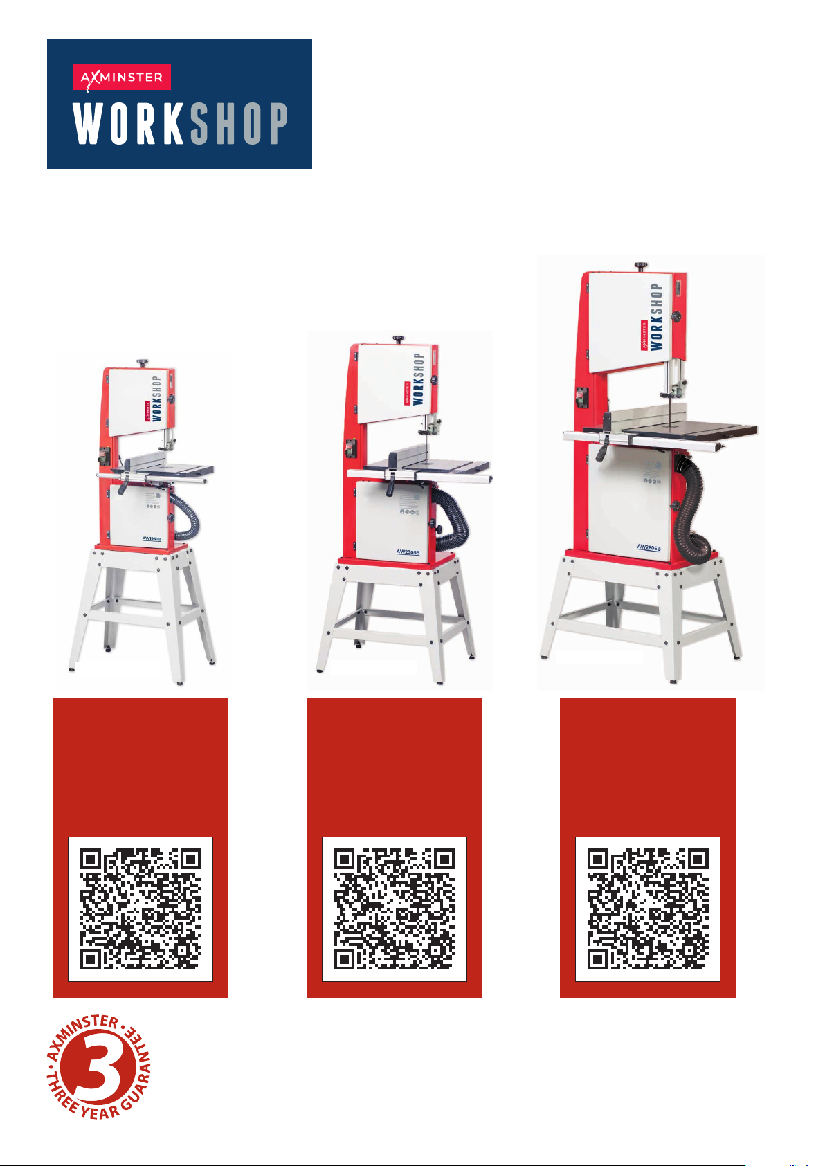
Bandsaws
10", 12" & 14" Inch
AW1950B Code 107711
AW2305B Code 107999
AW2606B Code 108000
Original Instructions
AW1950B
Watch
The Set Up
Guide
Here!
AW2305B
Watch
The Set Up
Guide
Here!
AW2606B
Watch
The Set Up
Guide
Here!
AT: 22/03/2023
BOOK VERSION:
08
Page 2
INDEX OF CONTENTS
EU Declaration of Conformity 02
What’s Included 03-04-05
Optional Accessories 03-05
General Instructions for 230V Machines 05
Specification 06
Assembly 06-07-08-09-10-11-12-13-14
Illustration and Parts Description 15-16-17-18-19-20
Setting Up the Saw 21-22-23
Operating Instructions 24
Changing the Saw Blade 25-26-27
Changing the Blade Speed 26
Maintenance 28
Bandsaw Blade Information 29-30
Bandsaw Trouble Shooting 31
UJK Bandsaw Buddy 32
Wiring Diagram 33
Exploded Diagrams/Lists 34-35-36-37-38-39-40-41-42-43
Cert No: MJ3420, MJ3425,
EU Declaration of Conformity
MJ343C, MJ343B
Axminster Tool Centre Ltd
Axminster Devon
EX13 5PH UK
axminstertools.com
declares that the machinery described:-
Type Bandsaw
Model AW1950B, AW2606B
Signed
Andrew Parkhouse
Operations Director
Da te: 05/11/2018
This machine complies with the following directives:
2006/42/EC
EN 1807-1:2013
EN 60204-1:2006+A1+AC
06/42/EC - Annex I/05.2006
and conforms to the machinery example for which the
EC Type-Examination Certificate No BM 50421300
has been issued by Laizhou Fulin Machinery Co., Ltd.
at: Wenchang Road Street Nanwuli Industry Yard Laizhou, Shandong261400
China
and complies with the relevant essential health and safety requirements.
The symbols below advise the correct safety procedures when using this machine.
Fully read manual
and safety instructions
before use
Ear protection
should be worn
Eye protection
should be worn
2
Dust mask
should be worn
HAZARD
Page 3
WHAT’S INCLUDED
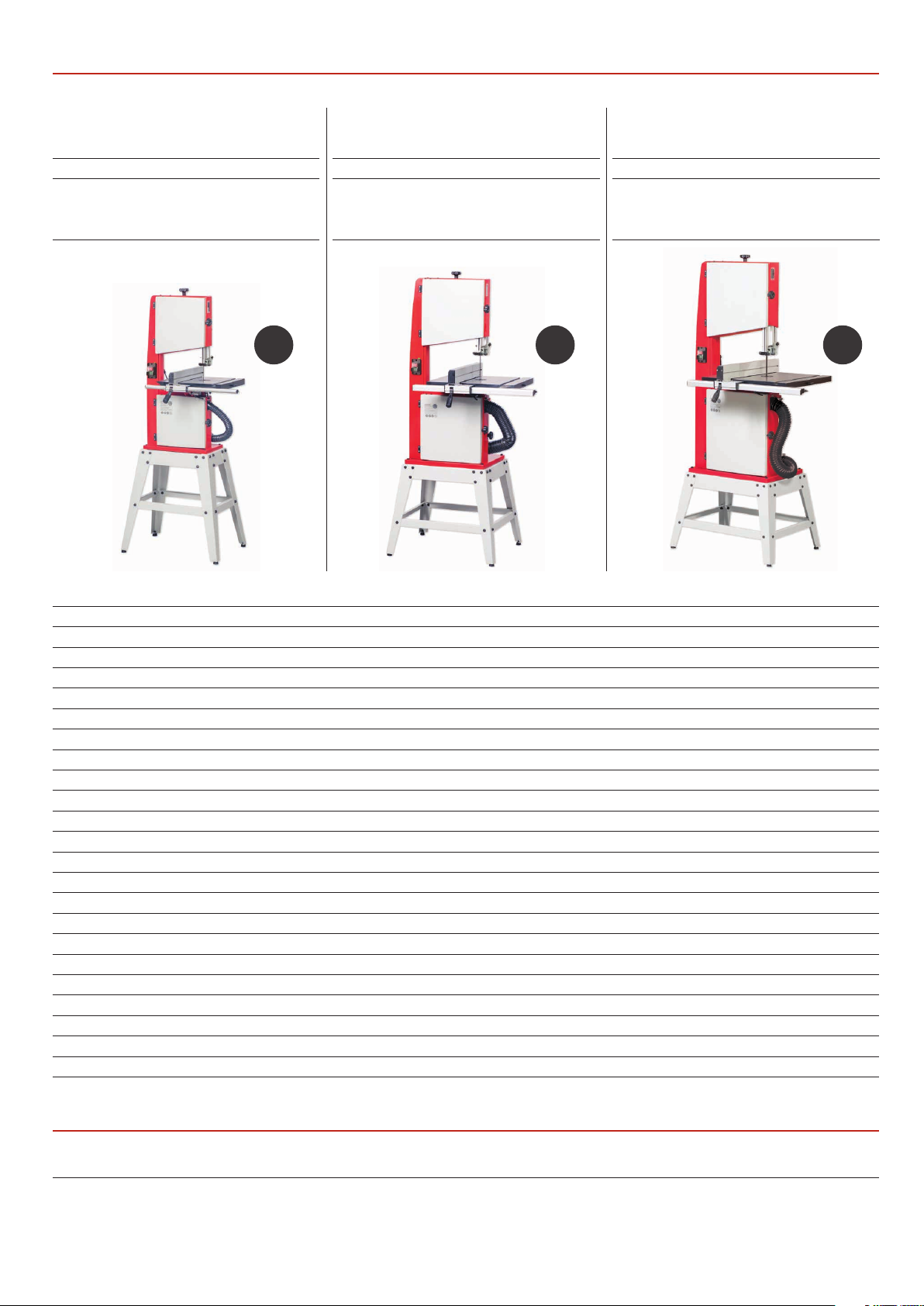
Model Number AW1950B Model Number AW2305B Model Number AW2606B
Quantity Item Part
1 107711 Bandsaw A
Blade 1,950mm long,
mounted on saw but not
tensioned
Quantity Item Part
1 107999 Bandsaw B
Blade 2,305mm long,
mounted on saw but not
tensioned
Quantity Item Part
1 108000 Bandsaw C
Blade 2,606mm long,
mounted on saw but not
tensioned
A B C
Quantity Item Part
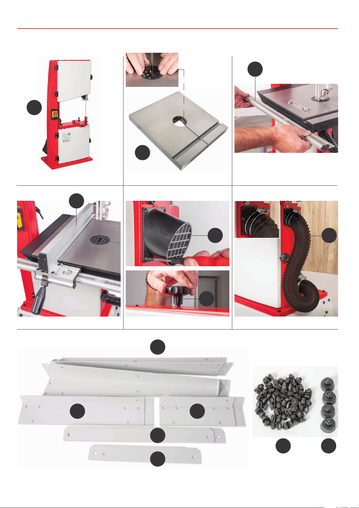
1 Craft Bandsaw Unit 1
1 Cast Iron Saw Table with Table Insert 2
1 Fence Guide Rail 3
1 Guide Fence Assembly 4
1 Extraction Port 5
1 Blade Tensioning Knob 6
1 Flexible Extraction Hose with Retaining Clips 7
1 Angled Pin and Nut 8
1 Push Stick 9
4 Long Bolts Washers & Nut 10
3 Hex Keys 11
2 Fence Rail Scale Strips (see pages 22-23 for mounting instructions)
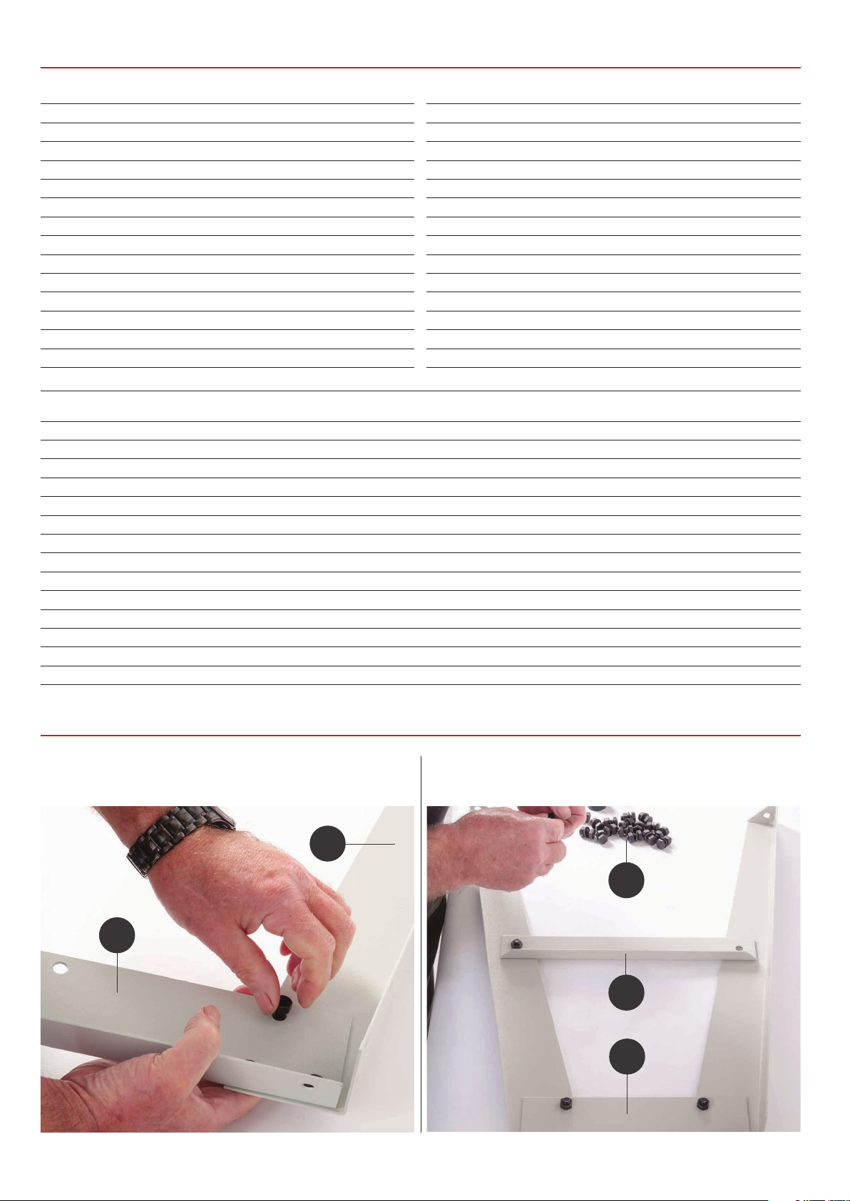
Floor Stand Comprising
4 Leg Brackets 12
2 Long Upper Support Struts 13
2 Short Upper Support Struts 14
2 Long Lower Support Struts 15
2 Short Lower Support Struts 16
4 Threaded Rubber Feet 17
1 Floor Stand Bag of fixings 18
OPTIONAL ACCESSORIES
Axminster Craft Mitre Fence (Code 104928) 19
3
Continues over...
Page 4
WHAT’S INCLUDED
1
3
2
4
12
6
5
7
13 14
15
16
4
18 17
Page 5
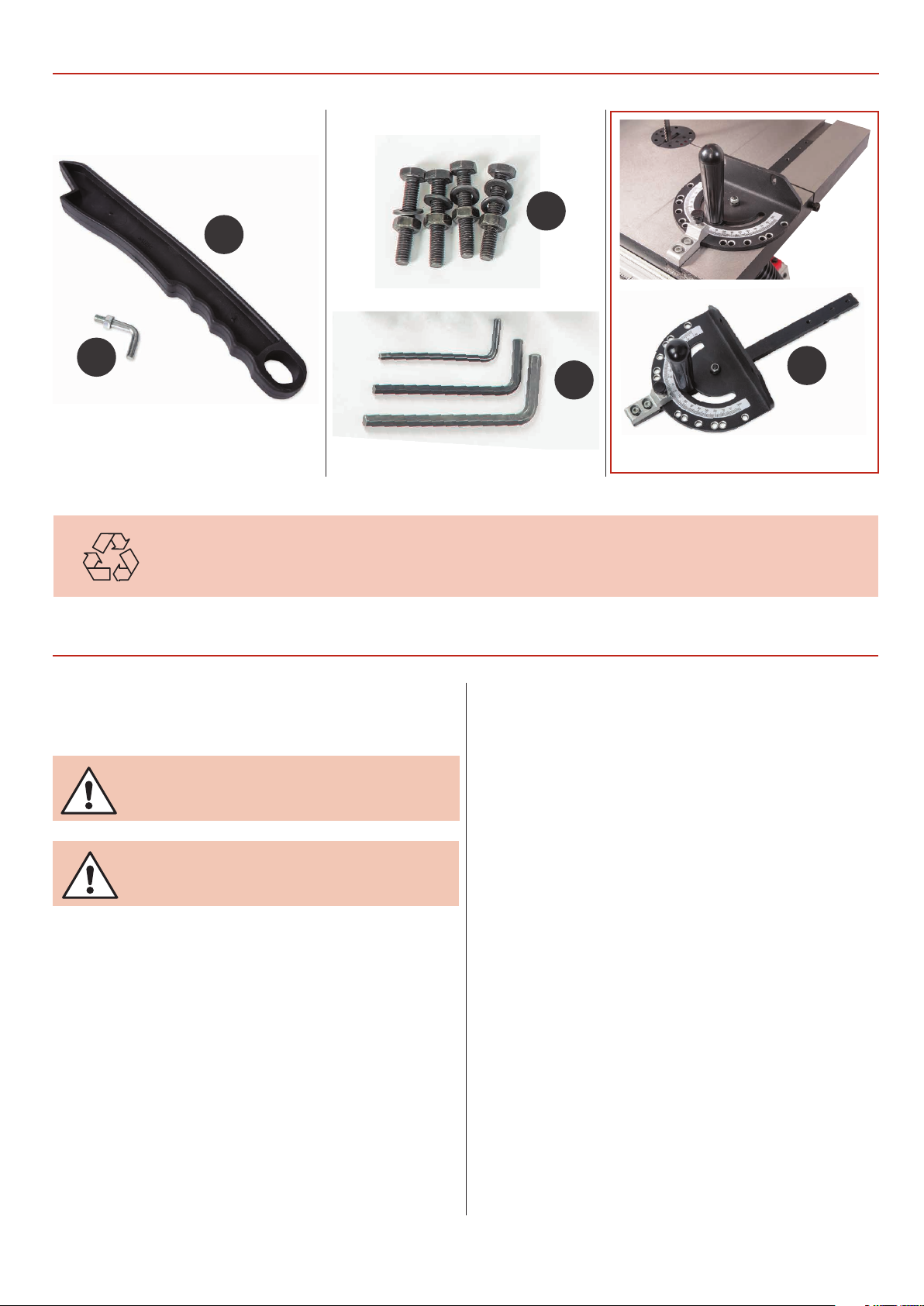
9
WHAT’S INCLUDED OPTIONAL ACCESSORIES
10
8
HAVING UNPACKED YOUR SAW (SEE BELOW) AND ITS ACCESSORIES PLEASE DISPOSE OF ANY
UNWANTED PACKAGING PROPERLY. THE CARDBOARD PACKAGING IS BIODEGRADABLE.
GENERAL INSTRUCTIONS FOR 230V MACHINES
The following will enable you to observe good working
practices, keep yourself and fellow workers safe and maintain
your tools and equipment in good working order.
WARNING!! KEEP TOOLS AND EQUIPMENT
OUT OF REACH OF YOUNG CHILDREN
KEEP WORK AREA AS UNCLUTTERED AS IS
PRACTICAL. UNDER NO CIRCUMSTANCES SHOULD
CHILDREN BE ALLOWED IN THE WORK AREA.
Mains Powered Tools
• Tools are supplied with an attached UK 13 Amp plug.
• Inspect the cable and plug to ensure that neither are
damaged. Repair if necessary by a suitably qualified person.
• Do not use when or where it is liable to get wet.
Workplace
• Do not use 230V a.c. powered tools anywhere
within a site area that is flooded.
• Keep machine clean.
• Leave machine unplugged until work is about to commence.
• Always disconnect by pulling on the plug body and not the
cable.
11
19
Optional Mitre Fence
• Carry out a final check e.g. check the cutting tool
is securely tightened in the machine and the correct
speed and function set.
• Ensure you are comfortable before you start work,
balanced, not reaching etc.
• Wear appropriate safety clothing, goggles, gloves,
masks etc. Wear ear defenders at all times.
• If you have long hair wear a hair net or helmet to prevent it
being caught up in the rotating parts of the machine.
• Consideration should be given to the removal of rings and
wristwatches.
• Consideration should also be given to non-slip footwear etc.
• If another person is to use the machine, ensure they are
suitably qualified to use it.
• Do not use the machine if you are tired or distracted
• Do not use this machine within the designated safety areas
of flammable liquid stores or in areas where there may be
volatile gases.
• Check blades are correct type and size, are undamaged
and are kept clean and sharp, this will maintain their
operating performance and lessen the loading on the
machine.
• OBSERVE…. make sure you know what is happening
around you and USE YOUR COMMON SENSE.
5
Page 6
SPECIFICATION
Code 107711
Model AW1950B
Rating Home Workshop
Power (Output) 550 W
Blade Speed 660 & 840 m/min
Blade Length 1,950mm
Blade Width Min/Max 6 mm to 13 mm
Max Width of Cut 260 mm
Max Width of Cut with Fence 185 mm
Table Size 350 x 330 mm
Table Height on Stand 1,035 mm
Table Tilt 0° - 45°
Dust Extraction Outlet 63 mm
Overall L x W x H 790 x 620 x 1,570 mm
Weight 39 kg
Code 108000
Model AW2606B
Rating Home Workshop
Power (Output) 1.1 kW
Blade Speed 600 & 840 m/min
Blade Length 2,606mm
Blade Width Min/Max 6 mm to 19 mm
Max Width of Cut 360 mm
Max Width of Cut with Fence 260 mm
Table Size 485 x 550 mm
Table Height on Stand 1,060 mm
Table Tilt 0° - 45°
Dust Extraction Outlet 100 mm
Overall L x W x H 980 x 760 x 1,740 mm
Weight 85 kg
Code 107999
Model AW2305B
Rating Home Workshop
Power (Output) 750 W
Blade Speed 360 & 720 m/min
Blade Length 2,305mm
Blade Width Min/Max 6 mm to 16 mm
Max Width of Cut 315 mm
Max Width of Cut with Fence 208.5 mm
Table Size 400 x 500mm
Table Height on Stand 1,035 mm
Table Tilt 0° - 45°
Dust Extraction Outlet 100 mm
Overall L x W x H 700 x 890 x 1,623mm
Weight 66kg
ASSEMBLY
Stand Assembly
Step 1 Step 2
12
18
14
16
14
6
Page 7
ASSEMBLY
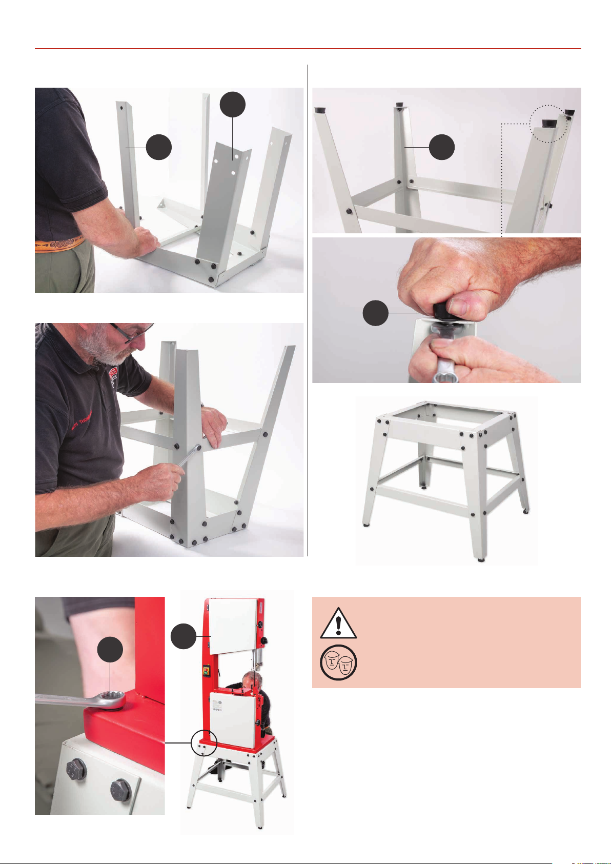
Step 3
Step 4
15
Step 5
13
12
17
Mounting the Bandsaw to the Stand
1
10
Step 6
WHEN MOUNTING THE UNIT, WE
STRONGLY ADVISE YOU GET THE
ASSISTANCE OF ANOTHER PERSON
AS THE BANDSAW IS HEAVY.
Lift the saw on to the stand, secure using four long bolts, nuts
and washers (10). Insert the bolts through the pre-drilled holes
in each corner of the base and through the floor stand. Fit the
washers and nuts on the underside and tighten to secure the
assembly.
7
Page 8
ASSEMBLY
Tensioning and tracking the blade
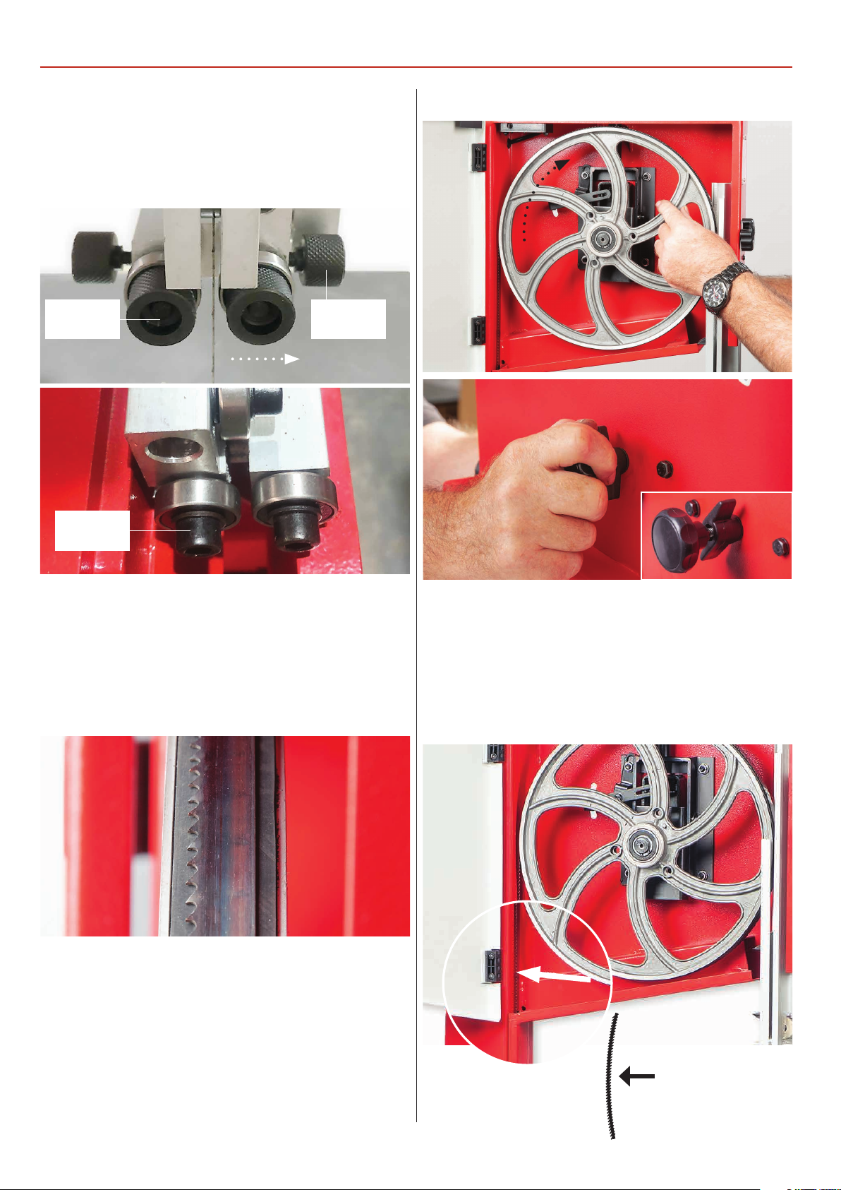
Make sure both top and bottom blade guides and thrust
bearing are well clear of the blade, see fig 01
Fig 01
Adjusting
knob
Clamping
knob
Fig 03-04
Clamping
bolt
1) Open the front covers fully, giving good access to the top
compartment of the saw and good visibility into the bottom
compartment, see page 14. For tracking the blade first adjust
all bearing guides so that they are well clear of the blade.
Check that the blade is sitting approximately in the middle
of the wheels, see fig 02.
Fig 02
3) Spin the top wheel again, check again. Continue until the
blade tracks in the centre of the tyres with no appreciable to
and fro movement. Tension the blade fully. A sideways push
on the blade should allow a maximum of 1 centimetre of
movement with moderate pressure on the blade, see fig 05.
Check the tracking again, adjust if necessary.
Fig 05
2) Apply some tension to the blade by turning the tensioning
wheel clockwise, spin the top wheel by hand and check that
the blade remains centrally on the tyre, see fig 03. If it does not,
adjust the tracking by turning the tracking control at the rear
of the head box, see fig 04. Viewed directly onto the tracking
control wheel, turning clockwise should cause the blade to
track to the rear of the tyre; anti-clockwise to the front, Note:
DO NOT make large adjustments otherwise you will over
correct yourself.
Sideways push on the
blade, max 1 centimetre
of movement
8
Page 9
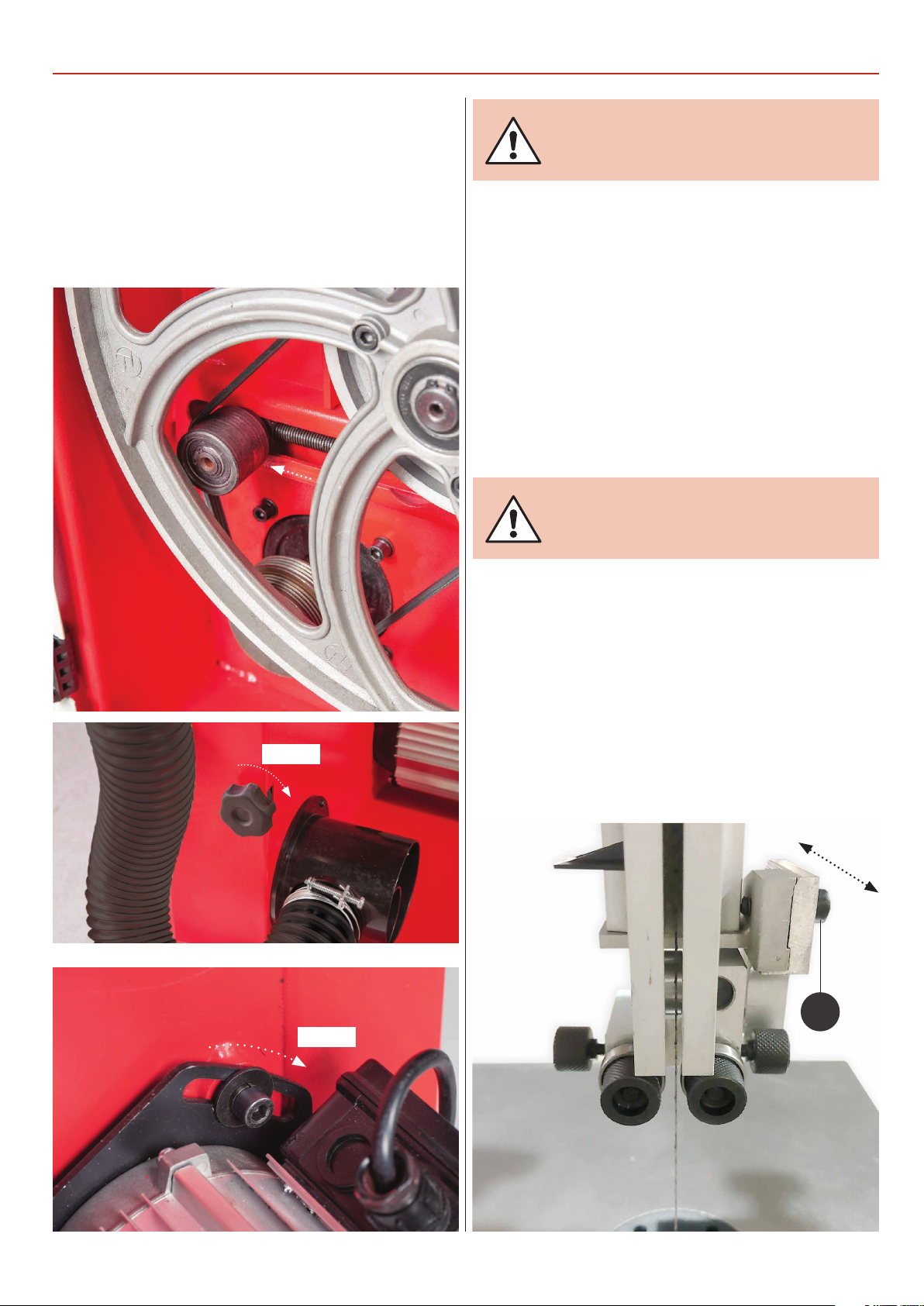
4) Check that the drive belt is tensioned correctly. If it is slack,
apply ‘take up’ pressure to the belt by adjusting the ‘Idler’ pulley,
using the knob at the side of the machine, see fig 06-07. Note
this applies only for model number AW2305B & AW2606B
bandsaw. To tension the drive belt on model AW1950B loosen
the motors clamping Hex bolt and press the assembly down.
While holding motor in place retighten the Hex bolt, see fig 08.
Fig 06-07-08
ASSEMBLY
CONNECT THE SAW TO THE
MAINS SUPPLY!
5) Stand clear and start the saw. Check that the saw is running
smoothly, (no thumps, bumps, knocking or excessive vibration)
and the blade appears to be tracking correctly (in one place).
You can check this by holding a marker, e.g. a pencil, close to
the back of the blade (approach from the back of the blade
only) and check that the gap remains constant.
If it doesn’t, adjust the tracking until it does, see fig 04.
Make very small adjustments and wait for the saw to react
before you adjust again, sometimes the reaction is not
instantaneous. Once you are satisfied that the tracking is
correct, switch the machine off and allow it to run to a stop.
DISCONNECT THE SAW FROM
THE MAINS SUPPLY!
Tighten
Tension
Setting the Blade Guides
1) Loosen the blade guide clamp and lower the upper blade
guide to approximately 1 1/2”(38mm) above the table, secure
in place.
2) Loosen the grub screw (A) holding the guide assembly in
place, adjust the fore and aft position so that the leading edge
of the guide bearing are approximately 2mm behind the gullets
of the saw blade. Re-tighten the grub screw, see fig 09-10-11.
Fig 09-10-11
A
9
Continues over...
Page 10
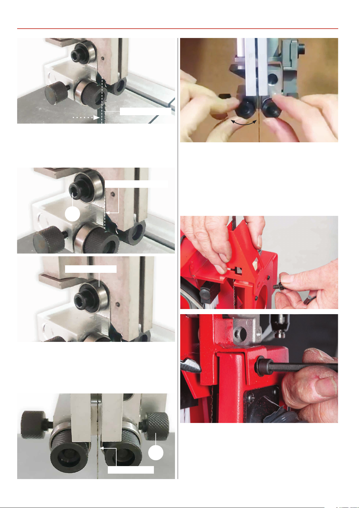
ASSEMBLY
2mm behind blade
3) Loosen the caphead bolt (B) that clamps the rear thrust
bearing, position the bearing so it’s 1mm behind the blade,
retighten the grub screw, see fig 12-13.
Fig 12-13
1mm behind the blade
5) Remove the lower blade guide guard and place safely
aside, see fig 16-17.
6) To set the fore and aft position on the lower guide
assembly, loosen the two cap head bolts (B) for models
AW2305B, AW2606B, see fig 18. For model AW1950B loosen
B
Rear thrust bearing
4) Loosen the two clamping knobs (A) holding the blade guides.
Adjust the guide bearings to approximately 0.5mm clearance
on either side of the blade. Re-tighten the clamping knobs (A),
see fig 14-15.
Fig 16-17
Fig 14-15
0.5mm clearance
A
the bolt to the under side of the bottom wheel housing, see fig
19. Note you may need to remove the lower wheel brush to
gain access to the bolt, see fig 20. Once complete secure the
assembly.
10
Page 11
ASSEMBLY
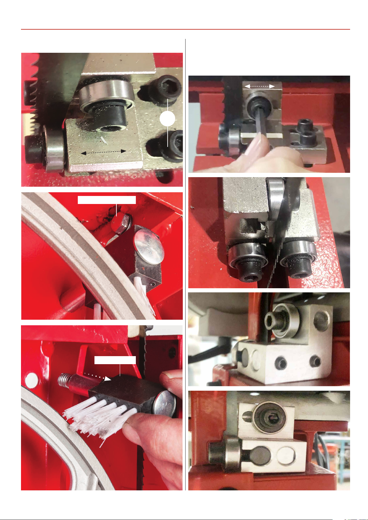
Fig 18-19-20
7) Repeat steps 3 and 4 on page 10 for setting the thrust
bearing and blade guides, see figs 21-22-23-24.
Fig 21-22-23-24
B
Guide assembly bolt
Wheel brush
11
Continues over...
Page 12
ASSEMBLY
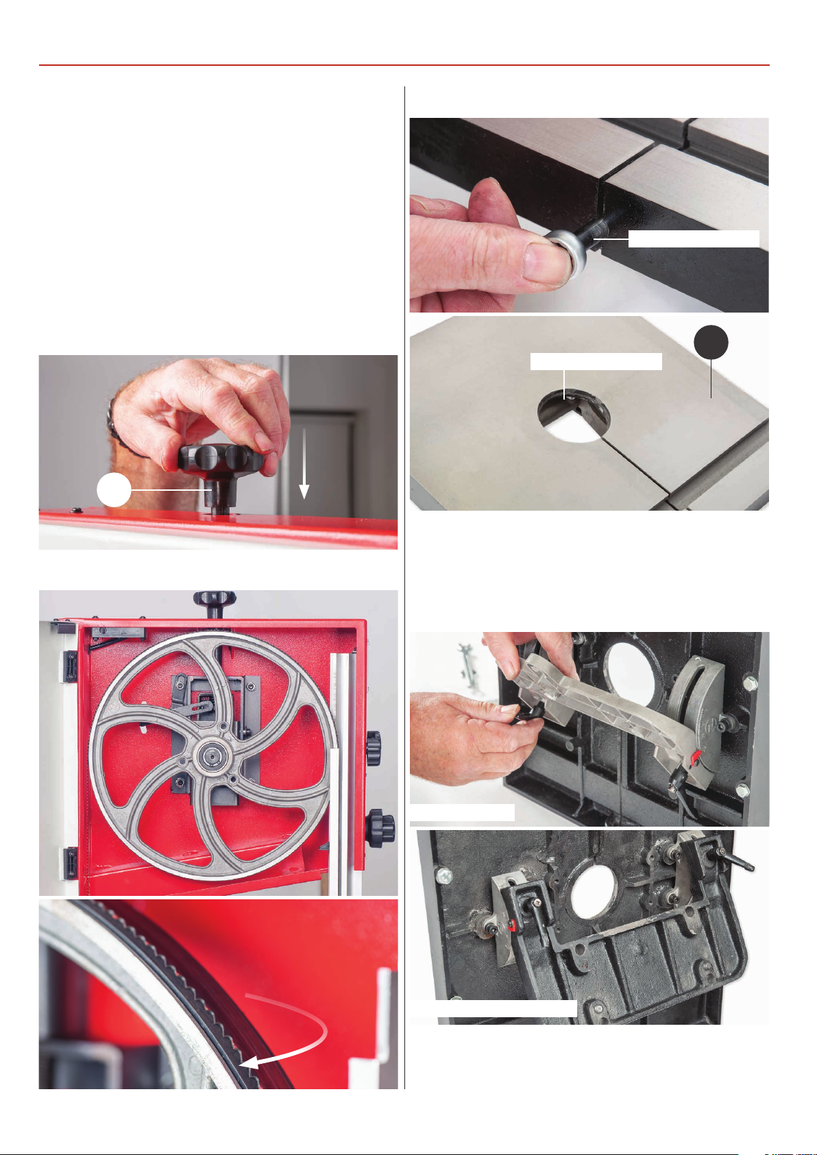
Mounting the Table
Locate the blade tensioning knob (6) and insert it down over
the control shaft ,on top of the bandsaw housing, see fig 25.
1) The saw table can be fitted without removing the blade.
However, if you would feel more comfortable not having to
manoeuvre the table around the blade, remove the blade by
opening the top and bottom covers, release the tension on
the blade by backing off the tensioning wheel, see fig 26-27.
NOTE: You will need to refer back to pages 8-11 for
tracking and setting the blade guides.
Fig 25
6
Fig 28-29
Table stabilising bolt
2
Table insert removed
Fig 26-27
2) Locate the cast iron table (2), remove the table stabilising
bolt and the table insert, see fig 28-29. Angle the tilt quadrant
assemblies base by loosening the two lift and shift handles
beneath the table in readiness for mounting, see fig 30-31.
Fig 30-31
Model AW1950B
Model AW2305B, AC2606B
3) Remove the bolts, washers/spring washers from the
bandsaws mounting plate and place safely aside, see fig 32-33.
Lift the table (2), slide the blade through the table’s slot and
12
Page 13
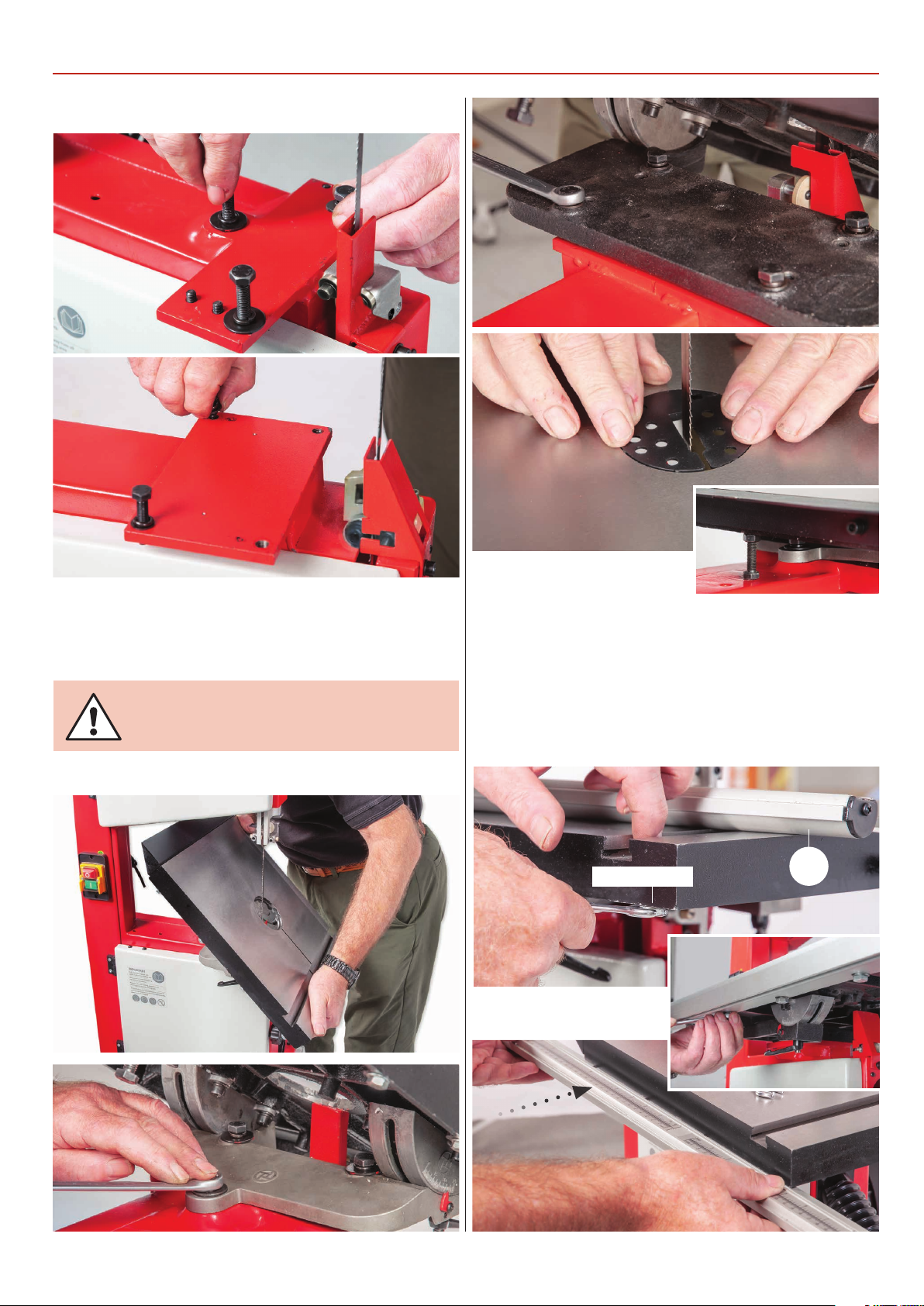
Fig 32-33
ASSEMBLY
lower onto the mounting plate, see fig 34. Line up the holes in
the tilt quadrant with the ones in the mounting plate, replace
the bolts/washers and tighten. Lower the table down on its
stop, replace table insert and stabilising bolt, see fig 35-36-37.
DO NOT OVERTIGHTEN!
Fig 34-35-36-37
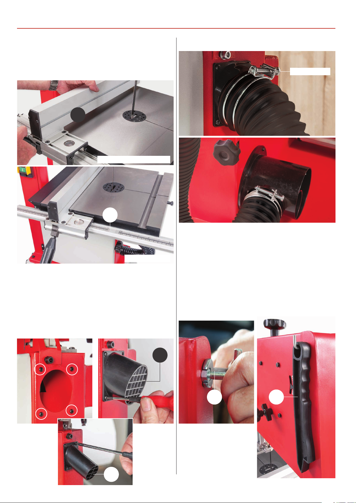
Fence Assembly
1) Locate the guide fence rail (3) and guide fence assembly (4).
Loosen the bolts beneath the table (2), giving enough
clearance between the table and bolts. Line up machined
slots in the fence rail (3) and slide the rail up against the table.
Nip up the bolts to secure the rail, see fig 38-39-40.
Fig 38-39-40
Loosen bolts
3
13
Continues over...
Page 14
ASSEMBLY
2) Locate the guide fence assembly (4), lowering the fence
down over the fence rail (3) and press down the locking lever
to secure the fence in position, see fig 41-42.
Fig 41-42
4
Model AW2305B, AW2606B
Fig 46-47
Retaining clip
3
Model AW1950B
Extraction Port & Hose Assembly
1) Find the extraction port (5), flexible hose and retaining clips
(7). Remove the four Phillips screws around the extraction
outlet beneath the table. Line up the holes in the extraction
port (5) and secure with the Phillips screws, see fig 43-44-45.
Fig 43-44-45
5
2) Place a retaining clip over the end of the hose (7), slide the
hose over the port (5) and tighten the clip. Repeat for the lower
extraction port, see fig 46-47.
3) Locate the angled pin and nut (8) and push stick (9). Screw
the nut onto the threaded pin then screw the pin into the
threaded hole to the rear of bandsaw and tighten with a
spanner. Slot the push stick (9) over the pin, see fig 48-49.
Fig 48-49
5
8 9
14
Page 15
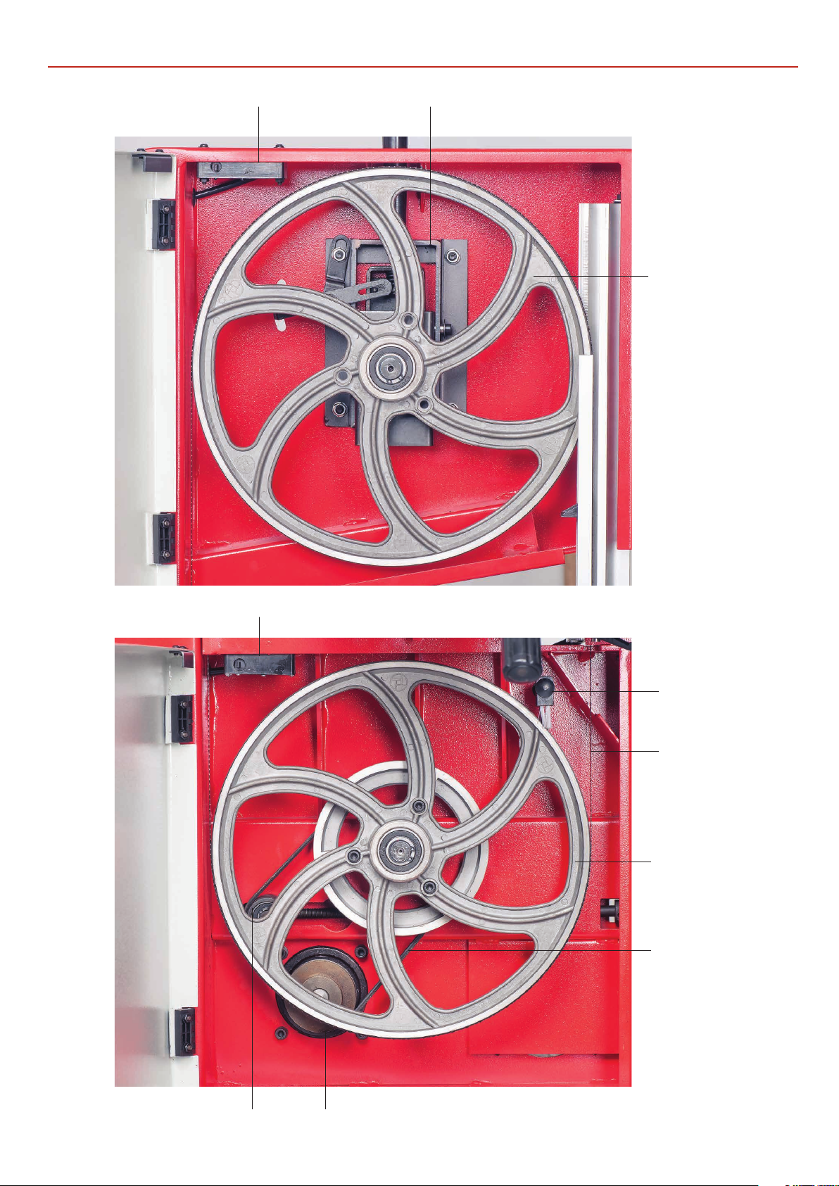
ILLUSTRATION AND PARTS DESCRIPTION
Upper wheel tracking and tensioning assemblyMicro switch
Upper saw wheel
Micro switch
Wheel brush
Bandsaw blade
Lower saw wheel
Drive belt
(AW2305B, AW2606B ONLY)
Drive pulleyTensioning idler wheel
15
Continues over...
Page 16
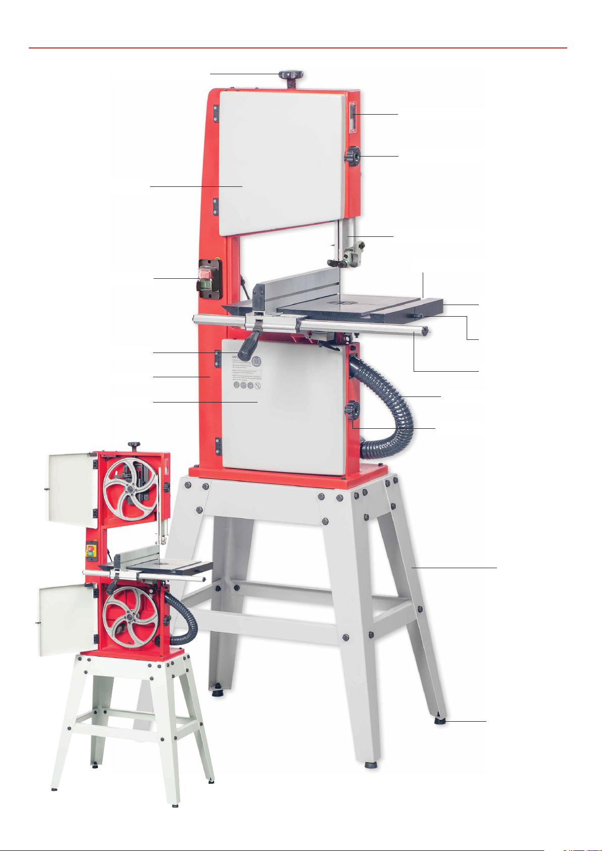
ILLUSTRATION AND PARTS DESCRIPTION
Blade tensioning knob
Upper door wheel
NVR On/Off switch
Blade observation window
Upper door locking knob
Upper blade guide & guard
‘T’ slot for mitre fence
Cast iron table
Fence locking lever
Saw frame
Lower door wheel
Stabilising bolt
Fence guide rail
Flexible extraction hose
Lower door locking knob
Floor stand
AW1950B Bandsaw
16
Rubber foot
Page 17
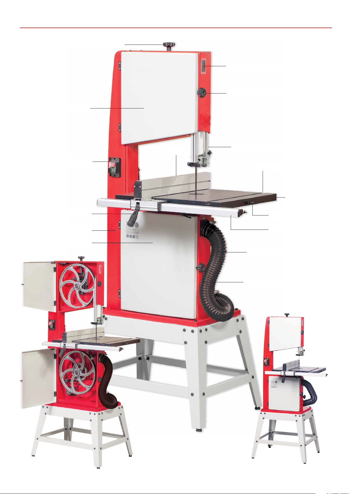
Blade tensioning knob
Upper door wheel
ILLUSTRATION AND PARTS DESCRIPTION
Blade observation window
Upper door locking knob
NVR On/Off switch
Fence locking lever
Saw frame
Lower door wheel
Fence
Upper blade guide & guard
‘T’ slot for mitre fence
Cast iron table
Stabilising bolt
Fence guide rail
Flexible extraction hose
Lower door locking knob
AW2606B Bandsaw
17
AW2305B Bandsaw
Page 18
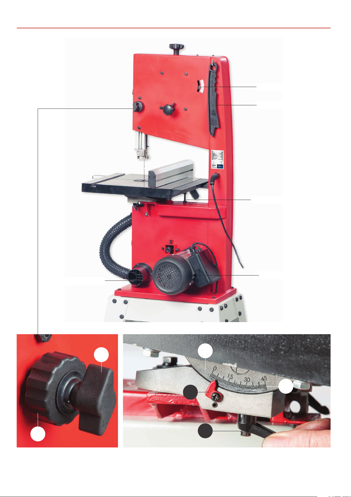
ILLUSTRATION AND PARTS DESCRIPTION
AW1950B Bandsaw
Blade tensioning scale
Push stick
Dust extraction outlet
A
Table levelling stop bolt
Motor assembly
C
B
Blade guide clamp (A)
Blade guide adjusting knob (B)
D
E
F
Tilt quadrant (C), Tilt scale (D)
Tilt scale pointer and adjusting screw (E), Lift and shift handle (F)
18
Page 19
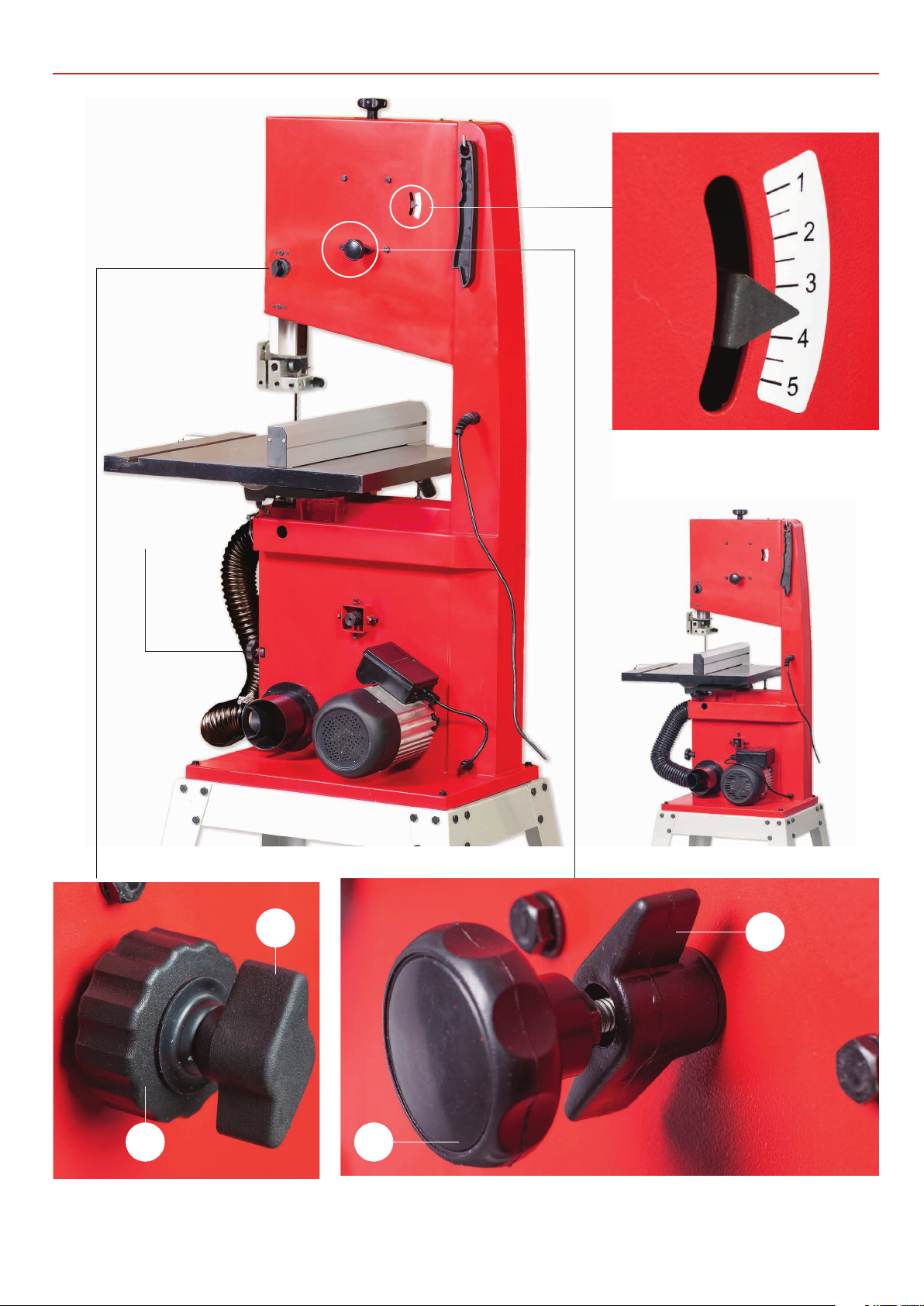
AW2305B Bandsaw
AW2606B Bandsaw
ILLUSTRATION AND PARTS DESCRIPTION
Blade tensioning scale
Idler wheel
adjusting knob
G
J
H
Blade guide clamp (G)
Blade guide adjusting knob (H)
I
Tracking control knob (I)
Tracking butterfly lock (J)
19
Page 20
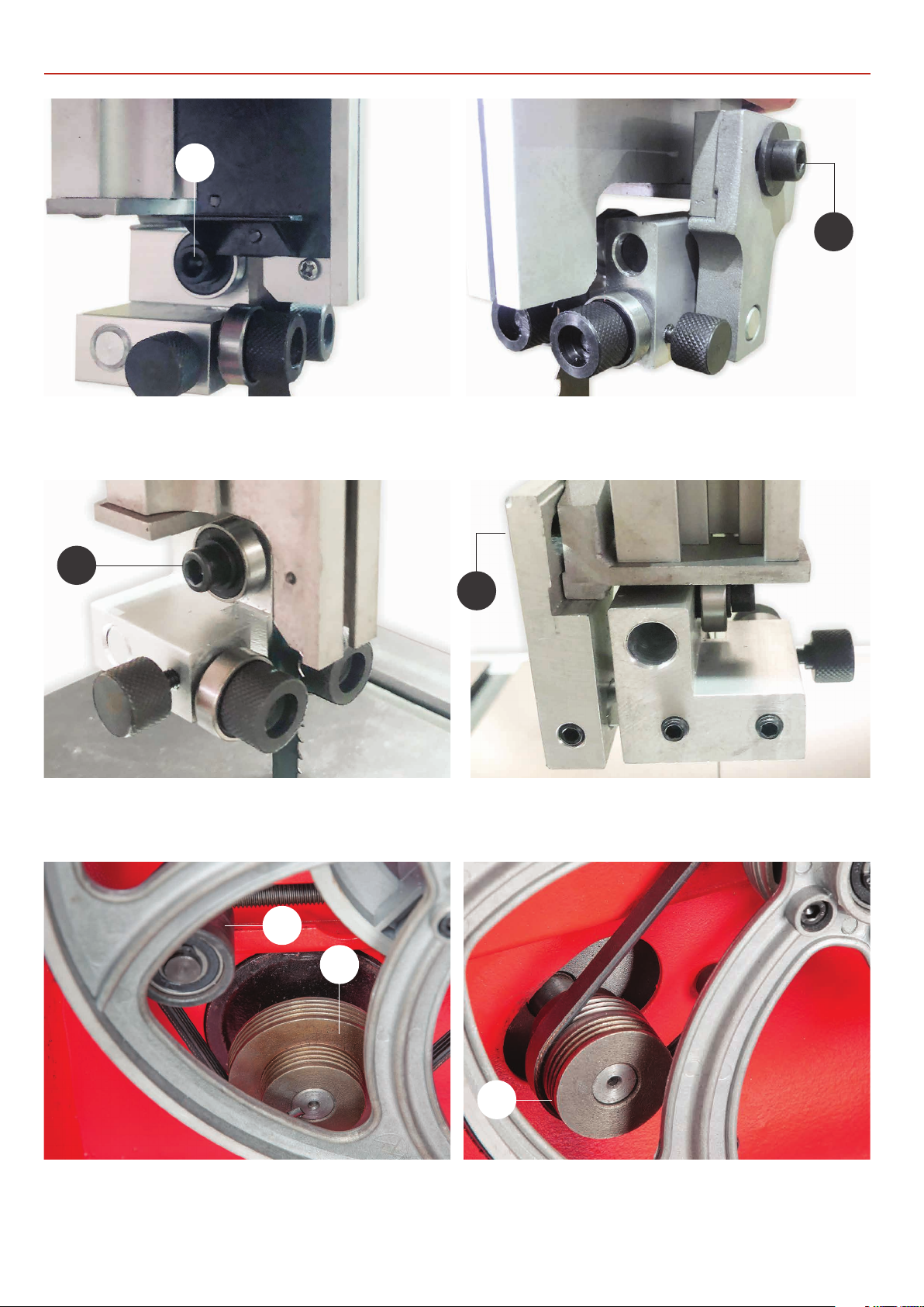
ILLUSTRATION AND PARTS DESCRIPTION
A
Upper blade guide assembly for AW2305B and AW2606B Bandsaw
Rear thrust bearing and clamping cap head bolt (A) Fore and aft clamping cap head bolt (B)
B
C
D
Upper blade guide assembly for AW1950B Bandsaw
Rear thrust bearing and clamping cap head bolt (C) Fore and aft clamping cap head bolt (D)
F
E
Drive assembly for AW2305B and AW2606B Bandsaw
Drive pulley (E) and Tensioning idler wheel (F)
G
Drive assembly for AW1950B Bandsaw
Two speed drive pulley (G)
20
Page 21
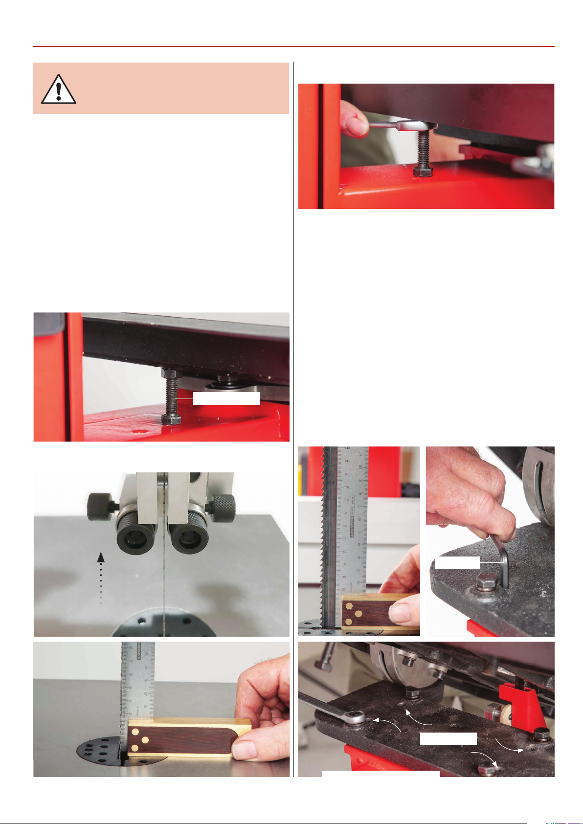
DISCONNECT THE SAW FROM
THE MAINS SUPPLY!
Checking the Table is Square
1) Loosen the clamping handle beneath the table, lower the
table until it rests against its stop. This is a bolt with a lock nut
screwed into the underside of the table, see fig 50. The head
of the bolt acts as a stop when it strikes the machine frame.
Tighten the clamping handles.
SETTING UP THE SAW
Fig 53
2) Loosen the blade guide clamp and raise the upper blade
guide assembly as high as possible, see fig 51. Place a
90˚square on the table and move it up against the blade
(behind the teeth), see fig 52.
Fig 50
Table stop bolt
Fig 51-52
3) Check that the blade is perpendicular to the table. If it is not,
try resetting the table by loosening the lift & shift handles and
adjusting the table stop nut until perpendicularity is achieved,
see fig 53.
4) Move the square up against the back of the blade and check
it’s square against the table, see fig 54. If adjustment is required
loosen the locking handles, pivot the table and lock in place.
Loosen the bolts holding the tilt quadrant, using a Hex key
adjust the four grub screws in the quadrant, see fig 55-56. For
model AW1950B, adjust the grub screws beneath the mounting
plate, see fig 57. Make small adjustments, lower the table and
postion the square as before. Continue until the blade is square
to the table. Tighten the tables bolts to secure in place. Note:
check the blade is still square against the table as shown in
fig 54 and make adjustments to the table stop if required.
Fig 54-55-56
21
Hex key
Grub screws
Model AW2305B, AW2606B
Continues over...
Page 22
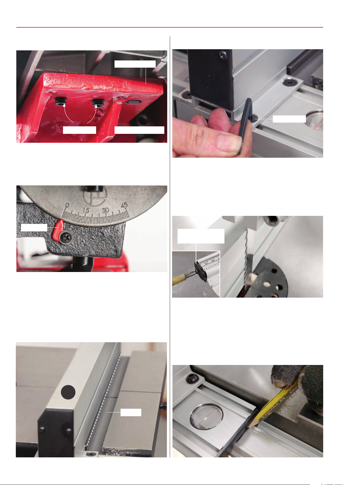
SETTING UP THE SAW
Mounting plate
Model AW1950BGrub screws
5) Lower the table down and check that the pointer of the tilt
scale reads zero, if not, loosen the screw and reposition the
pointer, see fig 58.
Fig 58
Fig 60Fig 57
Hex screw
1) Line up the fence (4) with the edge of the tables ‘T’ slot and
press down the locking handle., see fig 59. If the fence is out of
alignment, loosen the two Hex screws either side of the fence
clamping assembly. Adjust the fence until its in alignment with
the ‘T’ slot, retighten the Hex screws, see fig 60.
Pointer
Setting the Fence & Scale
The fence scale does not come pre-mounted to the fence rail
and needs to be stuck in place. NOTE: Before sticking the
scale down make sure the table and fence assembly is
square to the blade. Follow the instruction below.
Fig 59
Fig 61
Remove the fence
rail end cap
2) Position the fence against the blade and lock in place &
remove the fence rail end cap, see fig 61. Find a pencil and
draw a line on the fence rail to mark the position of the fence
assembly. Using a rule or vernier caliper, measure the distance
between the magnifying glass pointer and pencil line, see fig
62-63.
Fig 62-63
4
‘T’ Slot
22
Page 23
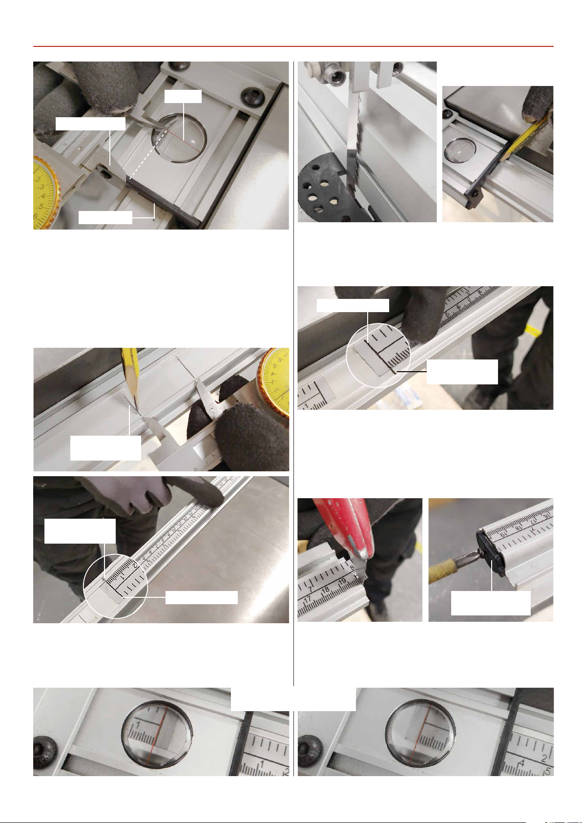
Vernier Caliper
Pencil line
SETTING UP THE SAW
Fig 67
Pointer
3) Remove the fence assembly and mark the position of the
magnifying glass pointer on the fence rail see fig 64.
4) Find the scale strips, peal off the backing from the long strip,
line-up the ‘Zero’ line on the scale with the pencil line and stick
it down onto the fence rail, see fig 65.
Fig 64-65
Pointer position
pencil mark
6) Position the fence to the opposite side of the blade and lock
in place, mark the position with a pencil as before, see fig 67.
Fig 68-69
Scale ‘Zero’ line
Pointer position
pencil mark
7) Repeat step 3, peal the backing from the short scale. Line-up
the ‘Zero’ line on the scale with the pencil line and stick it down
onto the fence rail, see fig 68. Trim any excess material from the
end of the fence rail and replace the rail end cap, see fig 69.
Fig 69
Pointer position
pencil mark
Scale ‘Zero’ line
5) Re-place the fence and slide it against the blade, the pointer
should read ‘ZERO’ on the scale, see fig 66.
8) Re-place the fence and slide it against the blade, the pointer
should read ‘ZERO’ on the scale, see fig 70.
Replace the fence
rail end cap
Fig 66 Fig 70
Magnifying Glass Pointer
set to ‘ZERO’
23
Page 24
OPERATING INSTRUCTIONS
1) Make sure you have read and fully understood the general
instructions and safety precautions that are printed in the
preceding pages of this manual.
2) Before connecting the machine to the supply; check the tool
for obvious signs of damage, paying particular attention to the
plug and the power cable. Rectify or have rectified any damage
you discover. Check that the blade you are using is the correct
one for the job in hand. Change the blade if necessary. Check
the blade is not damaged; is clean, sharp, tracks properly and is
correctly tensioned.
3) Set the upper blade guide to approximately 12mm (1/2”)
above the height of the work piece.
4) Check especially on site, that there are no foreign objects e.g.
old nails, screws, small stones etc embedded in the material you
are about to cut.
5) Check that all accessories, tools etc., that have been used
to set the machine up, are removed and set carefully aside or
stowed away correctly.
cut too quickly; the correct cutting speed, if one could be so
precise, would never see the blade pushed back against the
thrust bearing, the saw would cut and clear the saw line at the
rate the work piece was fed into it. If you notice that you require
more and more pressure to effect the cut, and the blade is in
continual contact with the thrust bearing, the chances are the
blade is becoming blunt. Check and change if necessary.
Do not let go of the work piece, if you have to change your grip,
make sure one hand is holding the material at all times.
9) If you are cutting long pieces of material think about sawing
cutouts (i.e. a saw cut from the edge of the material to the saw
line) along the saw line so that you can discard the off cuts as
you progress down the saw line.
10) Observe the old woodworkers’ adage of never allowing your
hand/fingers within one handbreadth of the blade.
USE THE SUPPLIED PUSH STICK
WHEN CUTTING SMALL PIECES.
UNDER NO CIRCUMSTANCES SHOULD
CHILDREN BE ALLOWED IN THE WORK AREA
AND KEEP TOOLS AND EQUIPMENT OUT OF
REACH OF YOUNG CHILDREN!
CONNECT A DUST EXTRACTION
MACHINE TO THE SAW.
Note: For the AC1950B we recommend a vacuum style extractor,
such as the AC50E, code 105251. For the AC2305B and AC2606B
we recommend a 1-1 ½ hp high volume extractor, such as the
AC 82E, code 105184.
6) Ensure the machine is switched off. Plug the power cable
into a correctly rated switched socket outlet. If extension leads
are being used, check these for damage, do not use if damaged;
if you are working outside, check that any extension cables in
use are rated for outside work. Switch on. Allow the saw to run
up to speed.
7) Make sure that the material you are about to cut is within the
machine is capacity, and the cut you are about to make is within
the blades’ capabilities, e.g. do not try to cut a 1” radius curve
using a 5/8” blade.
8) Make sure the blade is not in contact with the material when
you start the saw. Start the cutting operation. Do not try to
11) If you have to cut very small pieces of material, arrange
or manufacture some form of ‘shoe’ to carry the timber. If the
work piece is exceptionally small, find something to use as a
sacrificial carrier and mount the work piece on it with double
sided tape, or similar.
12) Remember to check the blade tension after a new blade
has been ‘working’ for 30-60 mins. The blade will ‘stretch’ slightly
when new.
13) Do not release the tension on the saw blade when work is
complete. The blades and the main saw frame do not respond
kindly to constant changes in stress and tension. Only release
the tension to change the blade or if the blade is to be removed
because the machine is to be ‘mothballed’ for a lengthy time
period. The blade in tension over a long period of non-use will
cause the tyres to develop ‘flat’ spot.
WARNING! IF THE SAW JAMS!
SWITCH OFF IMMEDIATELY.
14) Open the saw cut, either by pulling apart or driving a wedge
in close to the back of the blade. Try to wriggle the blade free of
the saw. If this is not possible; check that the saw is free in the
cut, start the saw, allow it to run up to speed and ‘cut out’ as
quickly as possible. The removal of the ‘off cut’ may well prevent
the saw jamming again if you resume the original cut).
24
Page 25
DISCONNECT THE SAW FROM
THE MAINS SUPPLY!
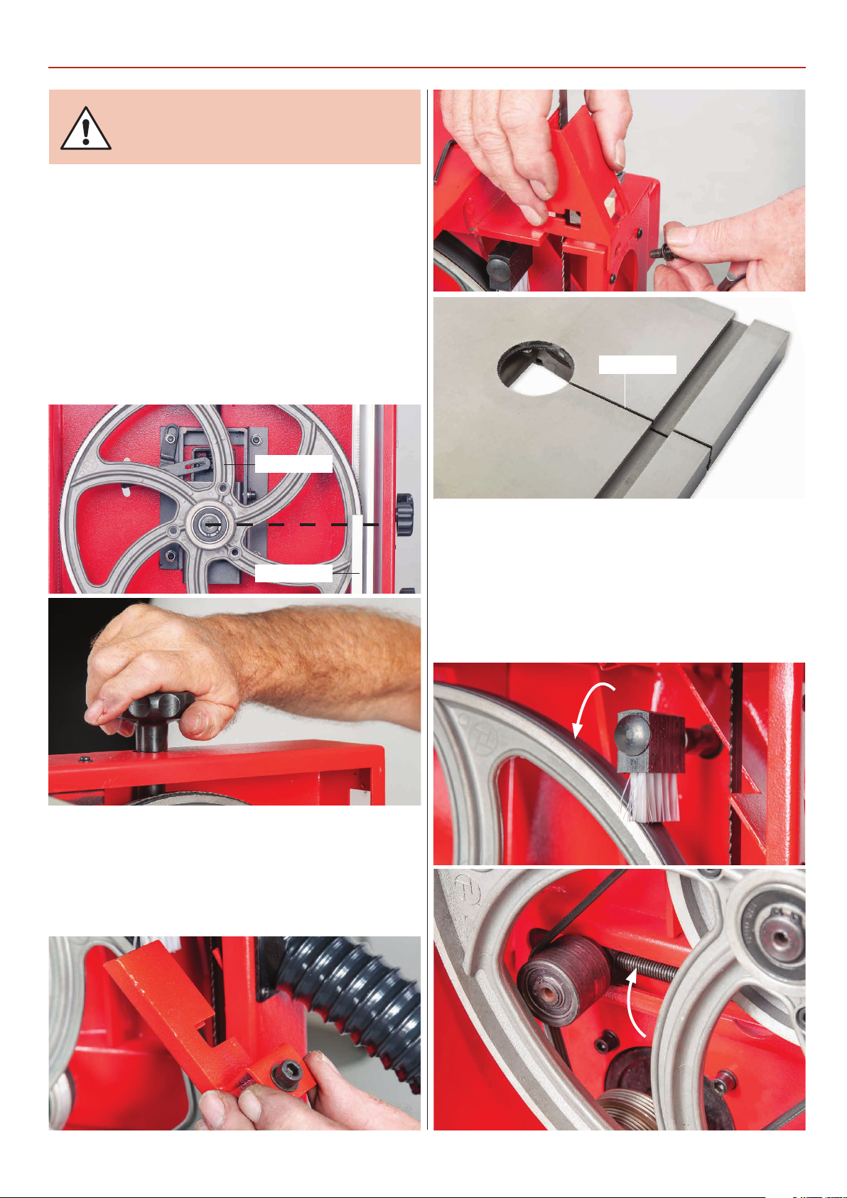
1) Put the table back to the level position if it has been tilted.
Open up all blade guides so that they are clear of the blade
and open the wheel doors. Set the upper blade guide assembly
approximately midway in the throat so the top of the blade
guide is level with the centre of the top drive wheel, see fig 71.
Remove the table insert.
2) Remove the table stabilising bolt, slacken the blade tension
by turning the blade tensioning wheel anti-clockwise, until the
blade can be easily slipped off the wheels, see fig 72.
Fig 71-72
Top wheel
CHANGING THE SAW BLADE
Table slot
Blade guide
3) Remove the upper and lower blade guide guards and place
safely aside, see fig 73-74. Remove the blade carefully, “wiggling”
it clear of the upper blade guard and out through the slot in
the table, 75.
Fig 73-74-75
4) This is a good time to clean out the interior of the machine;
remove the impacted ‘crud’ from the tyres, apply a little light oil
to the screw threads of the blade and drive belt tensioners and
the tracking control. The pivots and the slides of the top wheel
mounting assembly and the captive stub axle of the drive belt
tensioner in its slot could likewise be lightly oiled, see fig 7677-78.
Fig 76-77-78
25
Continues over...
Page 26
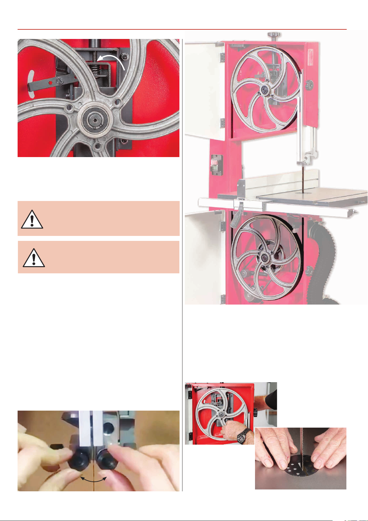
CHANGING THE SAW BLADE
Drive belt tensioner & tracking control assembly
5) If you are fitting a new blade, it will have been supplied to
you “folded”, bound together in this configuration with tape or
tie wrap.
WARNING! BE VERY CAUTIOUS WHEN
YOU “UNFOLD” THE BLADE; IT TENDS TO
‘SPRING’ OPEN, BLADE AND TEETH GOING
EVERYWHERE.
MAKE SURE THE BLADE
TEETH ARE POINTING DOWN!
6) Also check that the blade did not “unfold” inside out. i.e.
looking at the right side front of the loop, the teeth should be
on the front of the blade and pointing down. If you can’t arrive
at this view, turn the blade inside out from its current position
and look again.
7) Open up all blade guides so that they are clear of the blade.
Hold the blade approximately midway on either side of the
loop and feed it into the table slot. When you get to the table
insert cut out void, work the left side of the loop into the slot in
the guard in the neck of the main saw frame. “Wriggle” the right
hand side of the blade through the slot in the upper blade
guide assembly. Ease the blade over the wheels and locate the
blade in the lower/upper blade guides, see fig 79-80.
8) Apply some tension to the blade. Turn the top wheel by
hand, to ensure the blade will not skip off the wheels and the
blade is travelling in the blade guides. Apply a little more
tension and check by once again spinning the upper saw wheel
by hand, see fig 81. When you are sure that the blade is “ON”
and stable, re-fit the table stabilising bolt and re-fit the table
insert, see fig 82. Now adjust the blade guides as described in
‘Setting up the saw’on page 21.
Fig 79-80
26
Fig 81-82
Continues over...
Page 27
DISCONNECT THE SAW FROM
THE MAINS SUPPLY!
Bandsaw Speed Table
Model Min (Small Pulley) Max (Large Pulley)
AW1950B 660m/min 840m/min
AW2305B 360m/min 720m/min
AW2606B 600m/min 840m/min
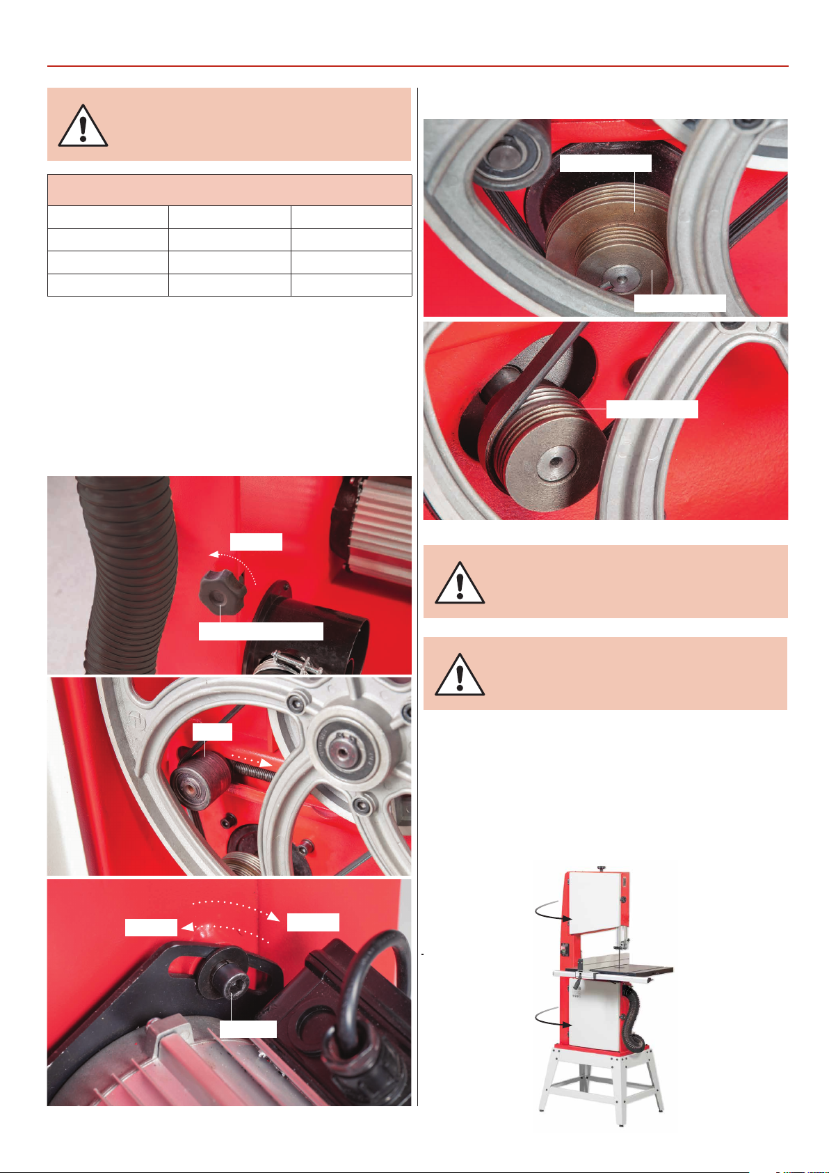
1) The bandsaw drive pulley has two speed positions. To
change the speed, follow the instructions below. Open the
bandsaw wheel doors and release the tension on the drive belt
by turning the idler wheel adjusting knob anti-clockwise, see
fig 83-84. Note: to release the belt tension on the AW1950B
bandsaw, loosen the motor Hex bolt, see fig 85 and pull the
motor up.
Fig 83-84-85
CHANGING THE SAW BLADE
Fig 86-87
Large pulley
Small pulley
Pulley grooves
Loosen
Loosen
Idler adjusting knob
Idler
Tension
WARNING! BE VERY CAREFUL WHEN
REMOVING THE BELT NOT TO TRAP
YOUR FINGERS!
NOTE: MAKE SURE THE BELT IS NOT
TENSIONED TO TIGHTLY TO CAUSE IT
TO GET HOT.
2) With the drive belt loose, carefully reposition the drive belt,
see fig 86-87. NOTE: Make sure the belt is seated correctly in
one of the drive pulley grooves. With the belt repositioned,
turn the Idler wheel adjusting knob clockwise to re-tension.
Push the motor down on the ‘AW1950B’ and tighten the bolt
to retention. Close the wheel doors.
Hex bolt
27
Page 28
MAINTENANCE
DISCONNECT THE SAW FROM
THE MAINS SUPPLY!
Daily
• Keep the machine clean.
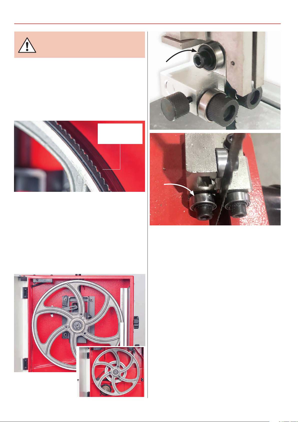
• Check the saw blade for missing teeth and cracks, see fig 88.
• Spray Axcaliber Dry Lubricant on the bare metal surfaces.
Fig 88
Check for missing
teeth and cracks in
the blade
Weekly
• Open the wheel doors and clean out all saw dust and
impacted ‘crud’ from the wheels and compartment area, see
fig 89-90. Note: using a vaccum cleaner, clean the motor vents
and casing.
• Check the condition of the upper/lower blade guide bearings
and thrust bearing. Clean any impacted ‘crud’ from the bearing,
see fig 91-92.
Fig 89-90-91-92
Monthly
• Open the lower and upper door and check the condition
of the tyres and the drive belt. Clean out all saw dust and
impacted ‘crud’ from the wheels and compartment area.
• Apply a little oil to the screw threads of the blade and
drive belt tensioners. DO NOT TO GET ANY OIL ON THE
TYRES AND DRIVE BELT.
• Check the condition of the tyres
• Check the blade for missing teeth and cracks
• Over time the drive belt can slacken, refer to the previous
page for tensioning the drive belt.
28
Page 29
BANDSAW BLADE INFORMATION
About Axcaliber Bandsaw Blades
Axcaliber bandsaw blades are manufactured at Axminster using
advanced CNC machining, high precision digital measuring
equipment and specialised heat treatment facilities. Detailed
quality checks are performed at each stage of manufacture
using the most modern inspection equipment. The result is a
blade which consistently cuts straighter, has harder, longer-life
teeth and which gives a superior finish to the work. The final
step in the manufacturing process is one of the most important;
the weld. We have invested heavily in this area through the
purchase of precision welding and grinding equipment and are,
as a result, one of the few companies worldwide able to offer a
fully guaranteed weld. Blades are cut accurately to length then,
using an IDEAL bandsaw blade welder, a high voltage current is
passed through the blade to achieve a precision butt weld.
The weld is annealed to remove any brittleness and danger of
fatigue and then hand dressed to produce a perfectly smooth
joint.
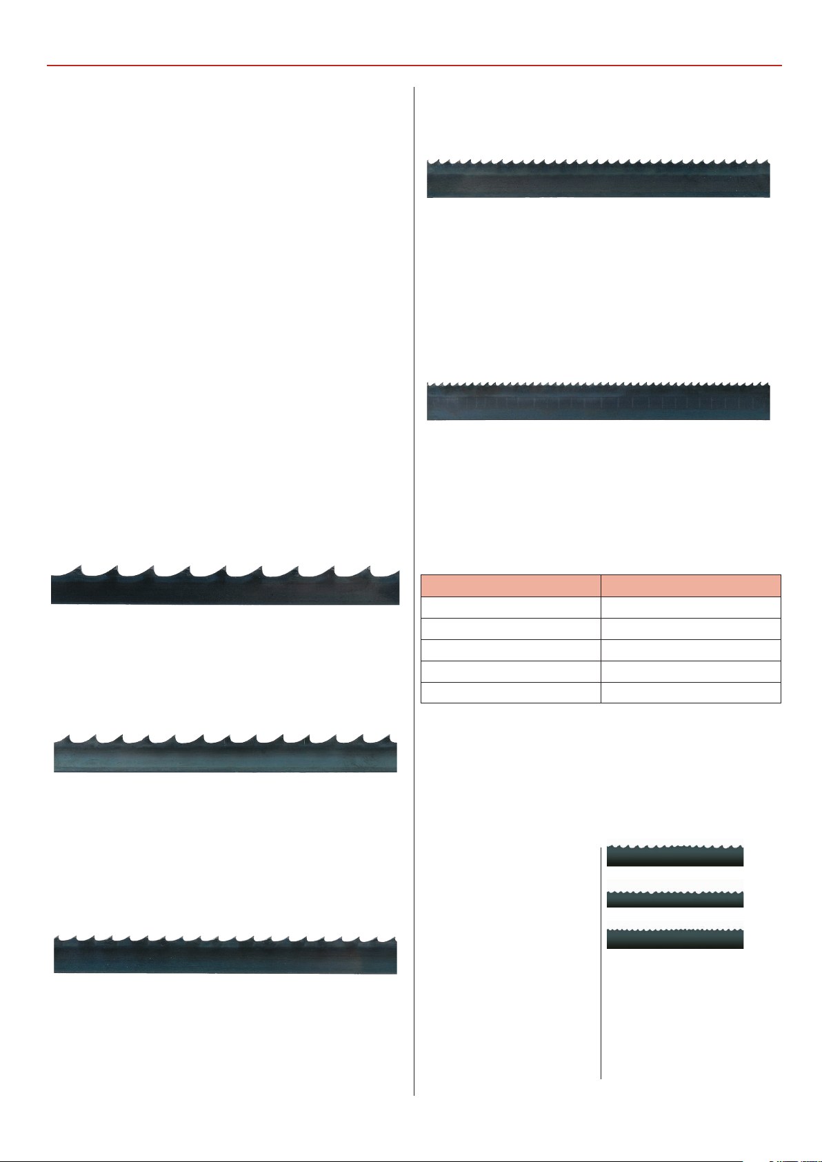
Choosing the Right Tooth Pitch (tpi)
3 tpi (skip form)
Used for deep cutting especially rip cuts, this blade will leave a
rough sawn finish although slow feed rate and high tension will
improve the finish of the cut.
of cut should not exceed 50mm. When cutting metals reduce
the speed as much as possible especially when cutting ferrous
metals or cast iron.
14 tpi (regular)
A very clean cutting blade for plywood, plastics and MDF
although too fine for natural timbers unless they are very thin
sections (sub 25mm thick). The 14tpi blade is very good to use
on slow speeds when cutting non-ferrous metals. A slow feed
speed should be used at all times with a blade tooth pitch this
fine.
Blade Width
Always use the widest saw blade possible; it is stronger and will
withstand greater feed pressures without flexing. Consult your
machine manual for the maximum and minimum blade widths
that it will accept. The minimum radius of curve for each blade
width is as follows:
4 tpi (skip form)
Good for general-purpose use with a degree of cutting across
the grain and with the grain, a reasonable finish can be
achieved with slower feed rates and good tension.
6 tpi (skip form)
The ideal general purpose blade suitable for cross cutting up
to 150mm and ripping in sections up to 50mm thick although
thicker sections can be cut using slow feed rates. This tooth
form will give a clean finish and is very well suited to natural
timbers.
10 tpi (regular)
Good for cutting plywood and MDF as well as non-ferrous
metals and plastics. The finish is good when cutting natural
timbers but the feed rate should be slow and maximum depth
Blade width Minimum radius
13mm (1/2”) 63mm (2 1/2”)
10mm (3/8”) 27mm (1 1/16”)
6mm (1/4”) 19mm (3/4”)
5mm (3/16”) 13mm (1/2”)
3mm (1/8”) 10mm (3/8”)
Blade Length
This is determined by your machine model. A list of the most
popular machines and their blade lengths is found in the
catalogue.
Blade Tooth Form
Standard Blade Tooth Forms:
4-6tpi
We supply bandsaw blades
with one of two tooth forms,
6-10tpi
skip or regular:
10-tpi
The skip tooth is provided on
coarse tooth blades, those
with 3, 4 and 6 teeth per inch;
it has a wide shallow gullet
with plenty of space for waste
to collect. Please note that
the quality of the cut can be
adversely affected by sawdust
packing between the teeth.
The regular, or triangular, tooth
form is provided on blades
with 10 or more teeth per inch
where, because of the reduced
material removal, there is less
need for waste storage.
29
Page 30
BANDSAW BLADE INFORMATION
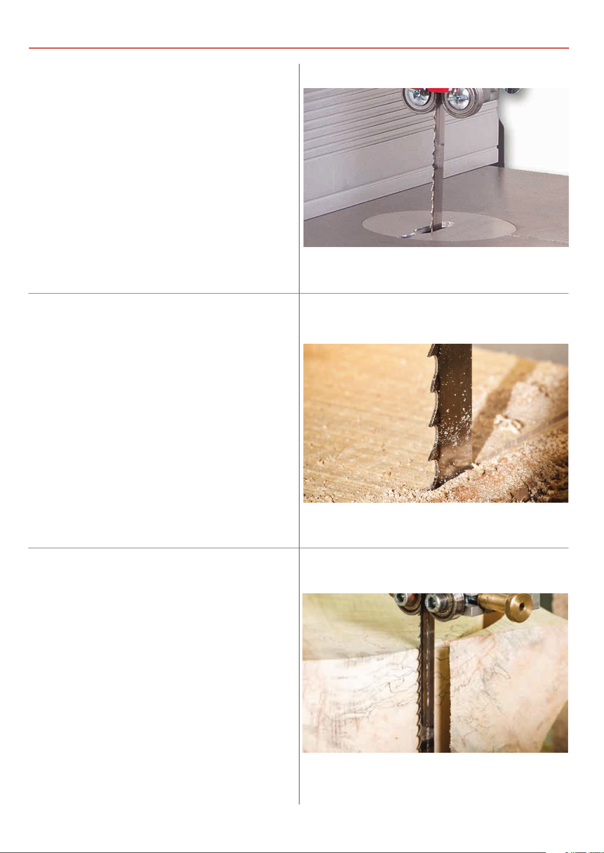
Premium Bandsaw Blades
•Premium blades made from M42 with 8% cobalt.
• Long life with high resistance to heat, abrasion and vibration.
• Variable pitch teeth for wider ranging applications.
• Also used for cutting metal on horizontal bandsaws. Blades
are available in three variable pitch forms 4-6tpi, 6-10tpi and
10-14tpi.
High Carbon Bandsaw Blades
• General purpose range of blades for wood and metal cutting.
• Comprehensive range of lengths widths and tooth
configuration.
• Hardened and long lasting teeth.
Ground Tooth Bandsaw Blades
• Diamond ground teeth staying sharper for at least 30% longer.
• Smoother cut over general purpose milled tooth blades.
• Comprehensive range of lengths, widths and tooth
configuration.
Back Tooth Bandsaw Blades
• Specifically designed for curve cutting so ideal for wood
turners.
• Back tooth design allows better clearance and tighter curves.
• Available in one width of 5/16” (8mm) x 4 tpi.
30
Page 31
BANDSAW TROUBLE SHOOTING
Trouble Shooting
Bandsaws are relatively simple machines and with all
machinery regular servicing (preventative maintenance) is
essential to get the best from your saw.
• This is the most common question
that you will get from bandsaw
users. Usually the answer lies within
‘My bandsaw
won’t cut
Straight”
“My bandasw
slows down
when cutting”
the blade; poor quality blades with
uneven set, the blade is blunt or
damaged often only on one side, the
tooth count is far too high for the
material being cut -remember 2 teeth
minimum and 10 teeth maximum in
the work piece.
• The fence is out of line with the blade.
• Check drive belt is tensioned
correctly.
• If cutting hard or wet material slow
your feed rate down.
• Check blade is sharp and not too fine.
• Make sure that when curve cutting a
narrow blade is used- see unit 5 blade
and cutter types.
Accessories
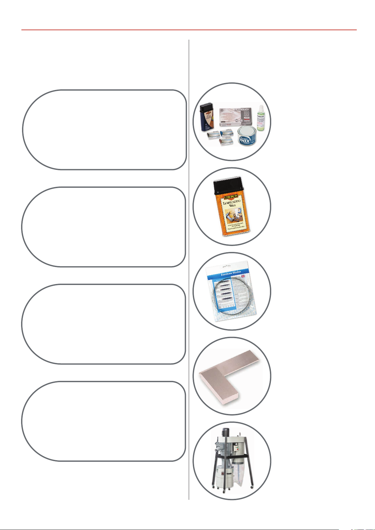
Below is the list of top recommended accessories and
up-sell items for the bandsaw. Please visit our website at
axminstertools.com
Axminster
Machine
Maintenance
Kit
Lubricants and
Maintenance
Tools
“My bandsaw
vibrates”
“Can I cut steel
on my
bandsaw?”
• Clean machine wheels.
• Check blade is running correctly on
wheels.
• Check blade weld – is it in line?
• Check machine is not on an uneven
floor.
• No , most woodcutting bandsaws run
far too fast to cut steel even if a metal
cutting blade is fitted.
Bandsaw
Blades
Squares
Cyclone
31
Extractors
Page 32
UJK BANDSAW BUDDY
Code: 101807
INTRODUCTION KEY FEATURES
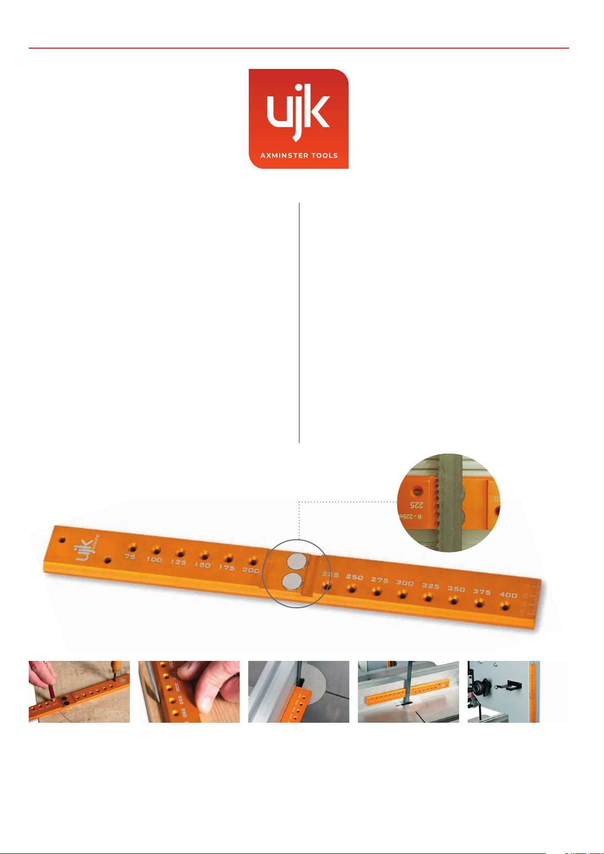
• Bandsaw Buddy is a unique bandsaw blade aligning tool.
Bandsaw Buddy allows you to check the alignment of the
bandsaw blade to the face of the fence. Most other checks
only require the use of a combination or engineer’s square.
Truing the fence to the blade is tricky. Bandsaw Buddy has
two rare earth magnets which hold it firmly on the blade. At
250mm long it is easy to spot any discrepancy and then make
necessary adjustments. The magnets will keep it safely stored
on the bandsaw’s frame when not in use.
• A scale on the tip helps set the bandsaw fence for cutting
veneers or thin boards. Holes along the Buddy’s length at
12.5mm intervals allow you to draw arcs or circles in 25mm
steps from 75mm to 400mm, a useful feature for marking
curves or when cutting bowl blanks. Accurately machined
from anodised aluminium, it also makes a handy straight edge.
• Designed and made in Axminster
• Unique bandsaw blade aligning tool
• Checks the alignment of blade to the face of the fence
• Rare earth magnets hold it firmly on the blade
• 250mm long makes it easy to spot any discrepancy
• Scale on the tip helps set fence for cutting veneers or thin
boards
• Holes for drawing circles in 25mm steps from 75 to 400mm
• Accurately machined from anodised aluminium
Marking Gauge Accurate Marking Thickness Gauge Perfect Alignment Keep your buddy on hand
An easy to use circle marking
gauge for bowl blanks from
75mm to 400mm radius in
increments of 25mm.
The bandsaw buddy can be used
as a straight edge for accurate
marking.
A convenient and accurate
metric thickness gauge, great
for veneering.
Rare earth magnets securely
hold the rule to the blade. This
enables you to align your rip
fence and table perfectly parallel
with the blade.
Once you’ve used your Bandsaw
Buddy the integrated magnets
allow simple storage on your
bandsaw
32
Page 33
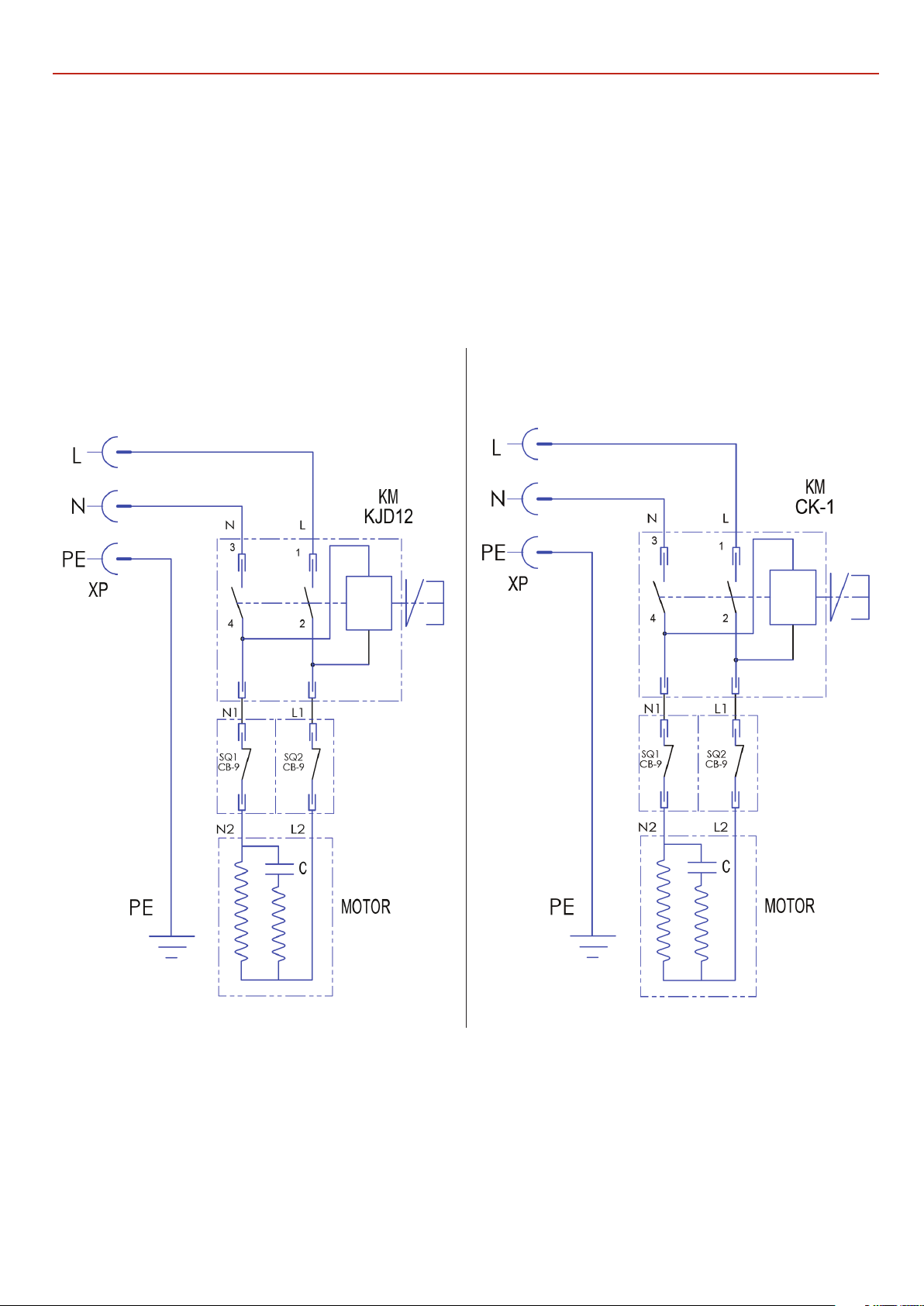
WIRING DIAGRAM
Model AW1950B Model AW2305B, AW2606B
33
Page 34
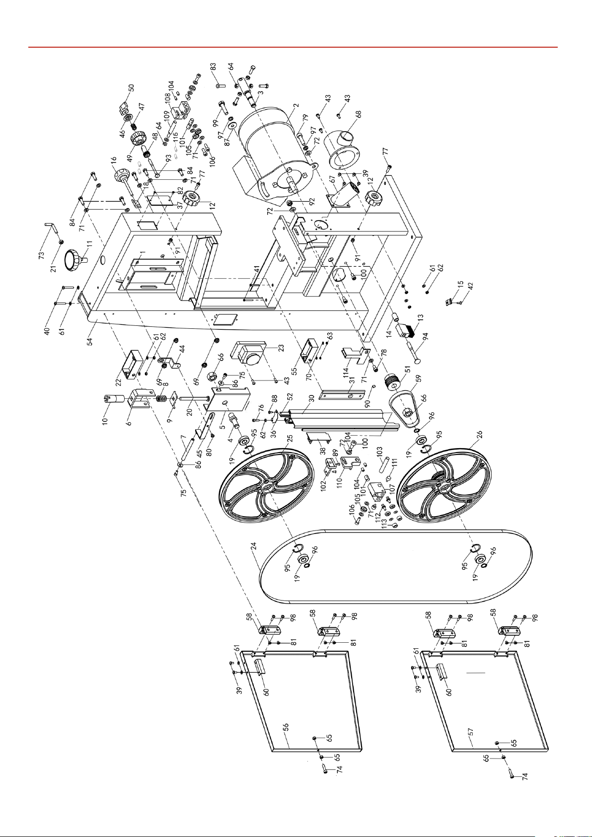
EXPLODED DIAGRAMSLISTS
AW1950B 10inch (Diagram A)
(3425-A)
34
Page 35
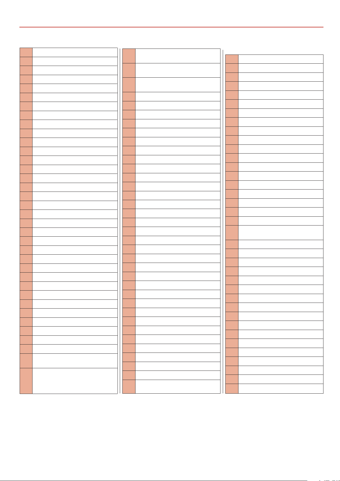
AC1950B 10inch (Parts List A)
EXPLODED DIAGRAMSLISTS
No. Description
1 Guide bracket
2 Motor
3 Lower wheel shaft
4 Upper wheel shaft
5 Upper wheel shaft seat
6 Sliding axle bracket
7 Upper wheel sliding axle
8 Spring
9 Strip washer
10 Adjusting nut
11 Adjusting knob
12 Door lock knob
13 Brush
14 Spacer bushing for brush
15 Cover clip
16 Setting knob
18 Wing nut
19 Bearing 80101
20 Step bolt
21 Hex.nut M6
22 Micro switch box
23 Switch
24 Blade
25 upper wheel
26 Lower wheel
27 Upper guide housing
28 Connection seat,upper guide
29 Connection shaft,upper guide
30 Upper guide guard
31 Upper guide guard base
36 Cover plate,upper guide guard
37 Sight glass
38 Protection board
39 Cross recessed pan head screw
M4X6
40 Cross recessed pan head screw
M4X30
41 Cross recessed pan head screw
M3X25
42 Cross recessed pan head screw
M5X8
43 Cross recessed pan head screw
M4X10
44 Pointer bending plate
45 Pointer
46 Dishing cover
47 Spring
48 Adjusting gear wheel,upper guide
49 Adjusting knob,upper guide
50 Wing nut
51 Motor pulley
52 Adjusting rack,upper guide
54 Saw frame
55 Micro switch box
56 Upper door
57 Lower door
58 Hinge
59 Drive belt
60 Touching plate,micro switch
61 Washer 4
62 Hex.nut M4
63 Hex.nut M3
64 Hex.nut M6
65 Hex.nut M5
66 Hex.nut M14x1.5
67 Side extraction adaptor
68 Bottom extraction adaptor
69 Anti-loosening nut M6
70 Washer 3
71 Washer 6
72 Washer 8
73 Push stick hook
74 Hex. socket cap head bolt M5X20
75 Hex. socket cap head bolt M5X10
76 Hex. socket cap head bolt M4X16
77 Hex. socket cap head bolt M5X16
78 Hex. socket cap head bolt M6X12
79 Hex. socket cap head bolt M8X20
80 Pointer screw
81 Cross recessed socket screw M4X14
82 Cross recessed socket screw M3X10
83 Hex.bolt M6X20
84 Hex.bolt M6X16
86 Washer 5
87 Washer 8
88 Taping screw ST3.5X10
89 Taping screw ST3.5X13
90 Hex.socket set screw M6X6
91 Self-locking nut M5
92 Self-locking nut M8
93 Step bolt M6X65
94 Step bolt M8X70
95 Circlips for holes 28
96 Circlips for shafts 12
97 Spring washer 8
98 Cross recessed pan head screw
M4X16
99 Hex.bolt M8X20
100 Hex. socket cap head bolt M8X16
101 Bearing nut
102 Connection seat,upper guide
103 Connection shaft,upper guide
104 Hex.socket set screw M6X10
105 Bearing 80026
106 Hex. socket cap head bolt M6X18
107 Bearing seat,upper guide
108 Bearing seat,lower guide
109 Connection shaft,lower guide
110 Connection board,upper guide
111 Locking nut
112 Eccentric shaft,upper guide
113 Bearing spacer,upper guide
114 Blade guard,lower guide
115 Hex.socket set screw M6X10
35
Continues over...
Page 36
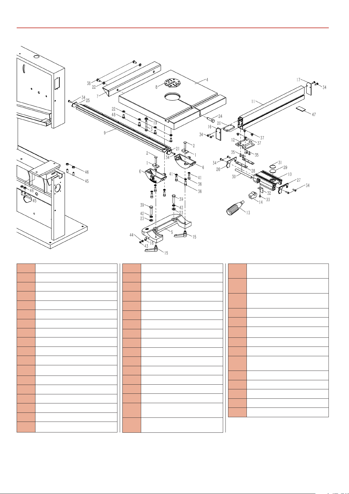
EXPLODED DIAGRAMSLISTS
AW1950B 10inch (Diagram & Parts List B)
(3425-B)
No. Description
1 Guide piece
2 Square neck bolt M6X25
3 Hex.bolt M8X45
4 Worktable
5 Mounting base,worktable
6 Rotating base,worktable
7 Extension table
8 Table insert
9 Front rail
10 Fence carrier
11 Rip fence
12 Fence plate
13 Lock handle,fence
14 Eccentric shaft
15 Ratchet lever
16 Front cap,fence
17 End cap,fence
18 Pointer
19 Hex.nut
20 Screw guide
21 Left cap,front rail
22 Washer 6
23 Washer 8
24 Table pin
25 Right cap,front rail
26 Left cap,fence carrier
27 Right cap,fence carrier
28 Screw guide
29 Pointer
30 Locking shaft,fence carrier
31 Circle ring
32 Lock plate
33 Cross recessed countersunk
screw M4X8
34 Cross recessed pan head
tapping screw ST4X16
35 Hex.socket cap head screw
M4X10
36 Hex.socket cap head screw
M6X16
37 Hex.socket pan head screw
M6X10
38 Hex.bolt M6X12
39 Hex.bolt M8X35
40 Hex.bolt M8X25
41 Spring washer 6
42 Spring washer 8
43 Cross recessed countersunk
screw M4X6
44 Washer 4
45 Hex.socket set screw M6X20
46 Hex.nut M6
47 Gasket board,rip fence
48 Hex.bolt M6X16
36
Page 37
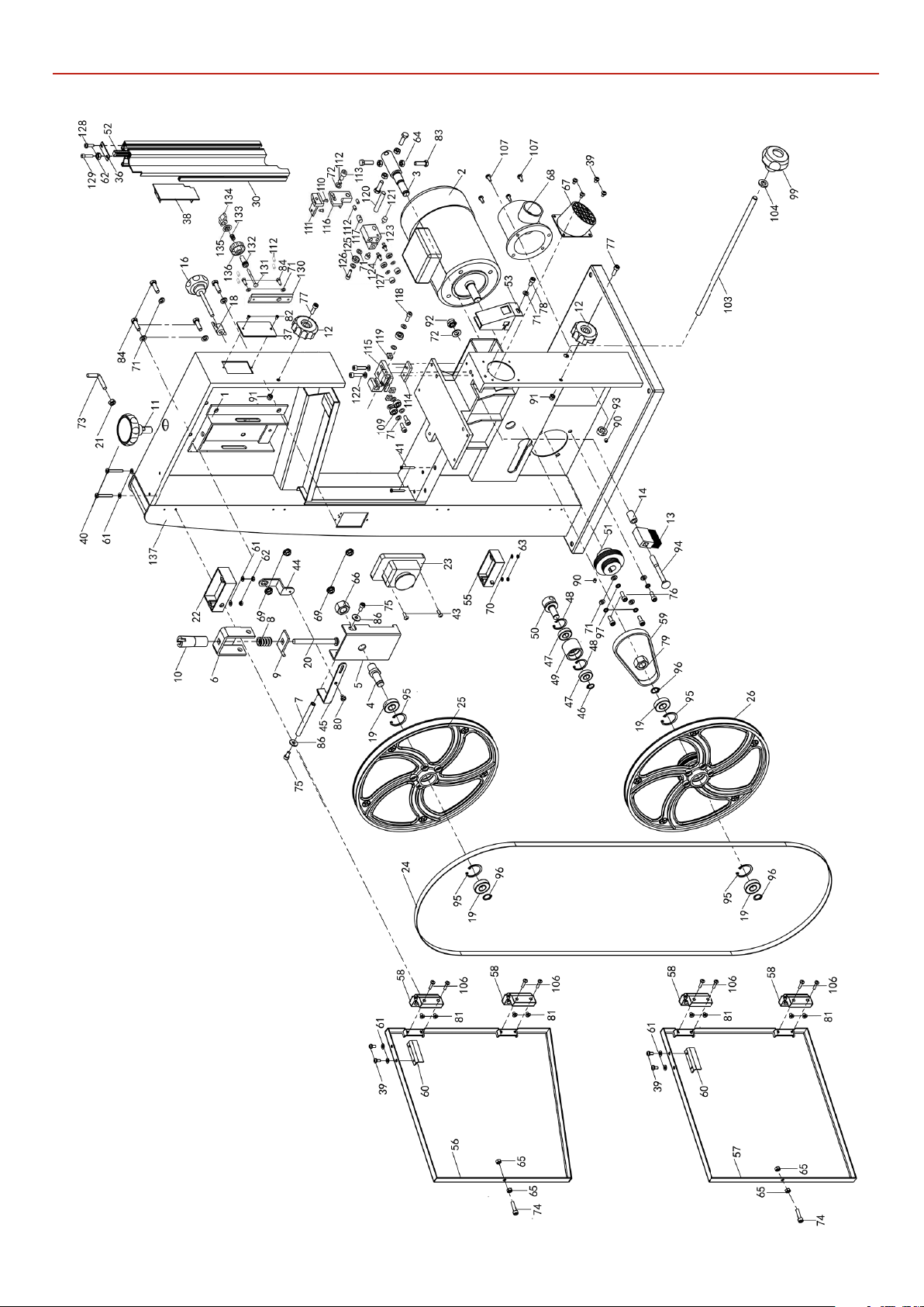
AW2305B 12inch (Diagram A)
EXPLODED DIAGRAMSLISTS
(343C-A)
37
Continues over...
Page 38
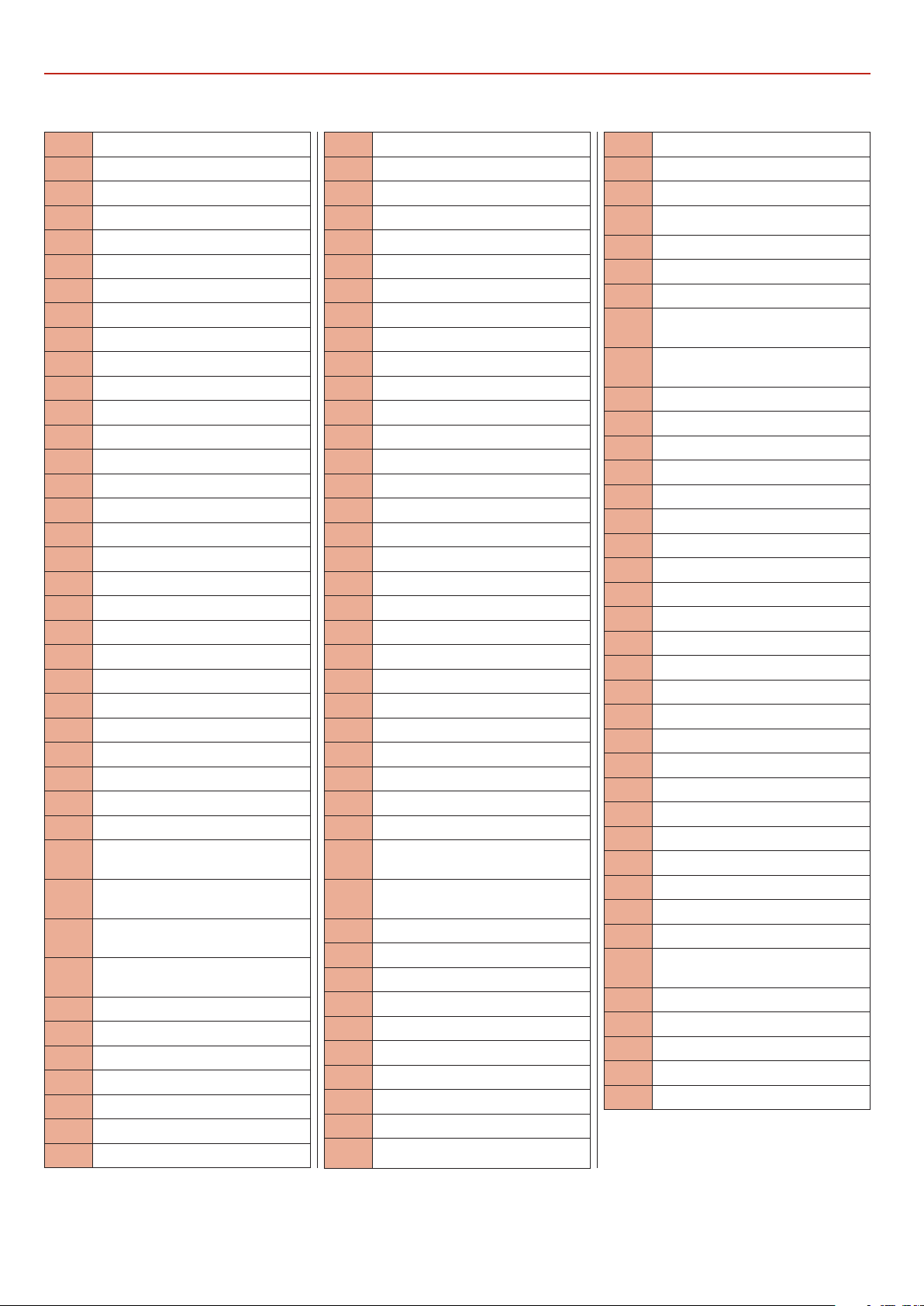
EXPLODED DIAGRAMSLISTS
AW2305B 12inch (Parts List A)
No. Description
1 Guide bracket
2 Motor
3 Lower wheel shaft
4 Upper wheel shaft
5 Upper wheel shaft seat
6 Sliding axle bracket
7 Upper wheel sliding axle
8 Spring
9 Strip washer
10 Adjusting nut
11 Adjusting knob
12 Door lock knob
13 Brush
14 Spacer bushing for brush
16 Setting knob
18 Wing nut
19 Bearing 80203
20 Step bolt M8X105
21 Hex.nut M6
22 Micro switch assembly
23 Power Switch
24 Saw blade
25 upper wheel
26 Lower wheel
30 Upper guide guard
36 Cover plate,upper guide guard
37 Sight glass
38 Protection board
39 Cross recessed pan head screw
M4X6
40 Cross recessed pan head screw
M4X30
41 Cross recessed pan head screw
M3X25
43 Cross recessed pan head screw
M4X10
44 Pointer bending plate
45 Pointer
46 Circlips for shafts 12
47 Bearing 80101
48 Circlips for holes 28
49 Tension pulley
50 Shaft for tension pulley
51 Motor pulley
52 Adjusting rack,upper guide
53 Lower guide guard
55 Micro switch ass’y
56 Upper door
57 Lower door
58 Hinge
59 Drive belt
60 Touching plate,micro switch
61 Washer 4
62 Hex.nut M4
63 Hex.nut M3
64 Hex.nut M6
65 Hex.nut M5
66 Hex.nut M14x1.5
67 Side dust port
68 Bottom dust port
69 Anti-loosening nut M6
70 Washer 3
71 Washer 6
72 Washer 8
73 Push stick hook
74 Hex. socket cap head bolt M5X20
75 Hex. socket cap head bolt M5X10
76 Hex. socket cap head bolt M6X16
77 Hex. socket cap head bolt M5X16
78 Hex. socket cap head bolt M6X12
79 Thin hex.nut M20X1.5
80 Pointer screw
81 Cross recessed socket screw
M4X14
82 Cross recessed socket screw
M3X6
83 Hex.bolt M6X20
84 Hex.bolt M6X16
86 Washer 5
88 Taping screw ST5X20
90 Hex.socket set screw M6X6
91 Self-locking nut M5
92 Self-locking nut M8
94 Step bolt M8X90
95 Circlips for holes 40
96 Circlips for shafts 17
97 Spring washer 6
99 Adjusting knob
100 Gear shaft
101 Gear wheel,upper guide
103 Belt tension shaft
104 Washer 10
105 Stop collar,belt tension shaft
106 Cross recessed pan head screw
M4X16
107 Cross recessed pan head screw
M5X10
109 Bearing 80101
110 Taping screw ST3.5X13
111 Connection seat,upper guide
112 Hex.socket set screw M6X10
113 Hex. socket cap head bolt M8X16
114 Nut board
115 Lower guide seat
116 Connection seat,upper guide
117 Bearing nut B
118 Hex. socket cap head bolt M6X16
119 Square nut
120 Connection shaft,upper guide
121 Locking nut
122 Hex. socket cap head bolt M6X25
123 Bearing seat,upper guide
124 Eccentric shaft,upper guide
125 Bearing 80026
126 Hex. socket cap head bolt M6X18
127 Bearing spacer,upper guide
128 Taping screw ST3.5X10
129 Hex. socket cap head bolt M4X16
130 Upper guide guard base
131 Step bolt M6X65
132 Adjusting gear wheel,upper
guide
133 Spring
134 Wing nut
135 Dishing cover
136 Adjusting knob,upper guide
137 Saw frame
38
Page 39
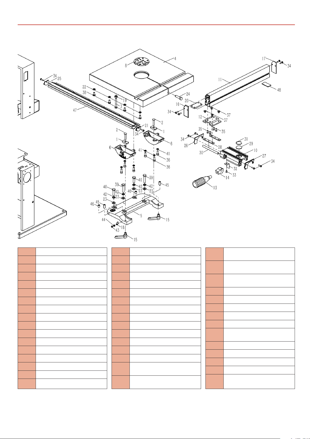
AC2305B 12inch (Diagram & Parts List B)
EXPLODED DIAGRAMSLISTS
(343C-B)
No. Description
1 Guide piece
2 Step bolt M6X25
3 Hex.bolt M8X45
4 Worktable
5 Mounting base,worktable
6 Rotating base,worktable
8 Table insert
10 Fence carrier
11 Rip fence
12 Fence plate
13 Lock handle,fence
14 Eccentric shaft
15 Ratchet lever M6
16 Front cap,fence
17 End cap,fence
18 Pointer
19 Hex.nut M8
20 Screw guide
21 Right cap,front rail
22 Washer 8
23 Washer 8
24 Table pin
25 Left cap,front rail
26 Left cap,fence carrier
27 Right cap,fence carrier
28 Screw guide
29 Pointer
30 Locking shaft,fence carrier
31 Circle ring
32 Lock plate
33 Cross recessed countersunk
screw M4X8
34 Cross recessed pan head tap-
ping screw ST4X16
35 Hex.socket cap head screw
M6X10
36 Hex.socket cap head screw
M6X16
37 Hex.socket pan head screw
M6X12
38 Hex.bolt M8X16
39 Hex.bolt M8X35
40 Hex.bolt M8X30
41 Spring washer 6
42 Spring washer 8
43 Cross recessed pan head screw
M4X6
44 Washer 4
45 Hex.socket set screw M10X20
46 Hex.socket set screw M10X12
47 Front rail
48 Gasket board,rip fence
39
Continues over...
Page 40
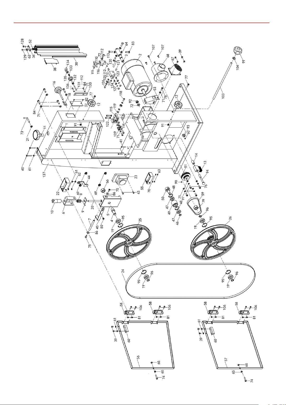
EXPLODED DIAGRAMSLISTS
AW2606B 14inch (Diagram A)
(343B-A)
40
Page 41
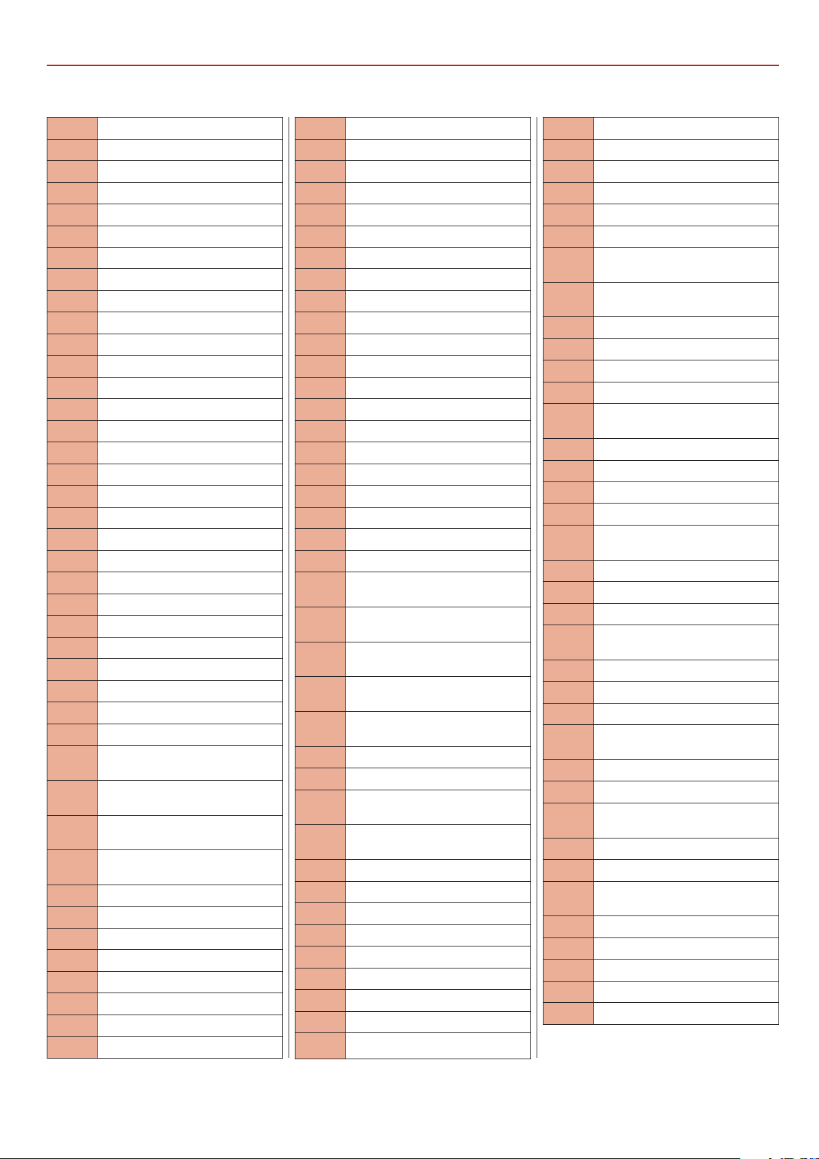
AW2606B 14inch (Parts List A)
EXPLODED DIAGRAMSLISTS
No. Description
1 Guide bracket
2 Motor
3 Lower wheel shaft
4 Upper wheel shaft
5 Upper wheel shaft seat
6 Sliding axle bracket
7 Upper wheel sliding axle
8 Spring
9 Strip washer
10 Adjusting nut
11 Adjusting knob
12 Door lock knob
13 Brush
14 Spacer bushing for brush
16 Setting knob
18 Wing nut
19 Bearing 80203
20 Step bolt M8X105
21 Hex.nut M6
22 Micro switch assembly
23 Power Switch
24 Saw blade
25 upper wheel
26 Lower wheel
30 Upper guide guard
36 Cover plate,upper guide guard
37 Sight glass
38 Protection board
39 Cross recessed pan head screw
M4X6
40 Cross recessed pan head screw
M4X30
41 Cross recessed pan head screw
M3X25
43 Cross recessed pan head screw
M4X10
44 Pointer bending plate
45 Pointer
46 Circlips for shafts 12
47 Bearing 80101
48 Circlips for holes 28
49 Tension pulley
50 Shaft for tension pulley
51 Motor pulley
52 Adjusting rack,upper guide
53 Lower guide guard
55 Micro switch ass’y
56 Upper door
57 Lower door
58 Hinge
59 Drive belt
60 Touching plate,micro switch
61 Washer 4
62 Hex.nut M4
63 Hex.nut M3
64 Hex.nut M6
65 Hex.nut M5
66 Hex.nut M14x1.5
67 Side dust port
68 Bottom dust port
69 Anti-loosening nut M6
70 Washer 3
71 Washer 6
72 Washer 8
73 Push stick hook
74 Hex. socket cap head bolt
M5X20
75 Hex. socket cap head bolt
M5X10
76 Hex. socket cap head bolt
M6X16
77 Hex. socket cap head bolt
M5X16
78 Hex. socket cap head bolt
M6X12
79 Thin hex.nut M20X1.5
80 Pointer screw
81 Cross recessed socket screw
M4X14
82 Cross recessed socket screw
M3X6
83 Hex.bolt M6X20
84 Hex.bolt M6X16
86 Washer 5
88 Taping screw ST5X20
90 Hex.socket set screw M6X6
91 Self-locking nut M5
92 Self-locking nut M8
94 Step bolt M8X100
95 Circlips for holes 40
96 Circlips for shafts 17
97 Spring washer 6
99 Adjusting knob
103 Belt tension shaft
104 Washer 10
105 Stop collar,belt tension shaft
106 Cross recessed pan head screw
M4X16
107 Cross recessed pan head screw
M5X10
109 Bearing 80101
110 Taping screw ST3.5X13
111 Connection seat,upper guide
112 Hex.socket set screw M6X10
113 Hex. socket cap head bolt
M8X16
114 Nut board
115 Lower guide seat
116 Connection seat,upper guide
117 Bearing nut B
118 Hex. socket cap head bolt
M6X16
119 Square nut
120 Connection shaft,upper guide
121 Locking nut
122 Hex. socket cap head bolt
M6X25
123 Bearing seat,upper guide
124 Eccentric shaft,upper guide
125 Bearing 80026
126 Hex. socket cap head bolt
M6X18
127 Bearing spacer,upper guide
128 Taping screw ST3.5X10
129 Hex. socket cap head bolt
M4X16
130 Upper guide guard base
131 Step bolt M6X65
132 Adjusting gear wheel,upper
guide
133 Spring
134 Wing nut M6
135 Dishing cover
136 Adjusting knob,upper guide
137 Saw frame
41
Page 42
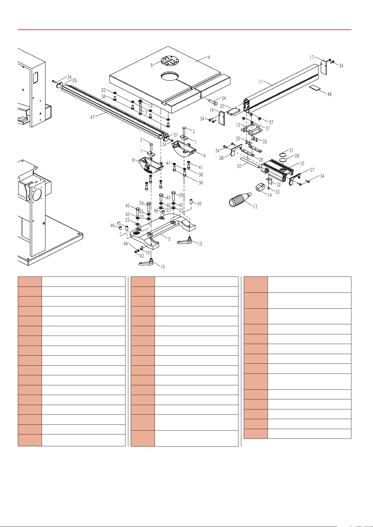
EXPLODED DIAGRAMSLISTS
AW2606B 14inch (Diagram & Parts List B)
(343B-B)
No. Description
1 Guide piece
2 Square neck bolt M6X25
3 Hex.bolt M8X45
4 Worktable
5 Mounting base,worktable
6 Rotating base,worktable
8 Table insert
10 Fence carrier
11 Rip fence
12 Fence plate
13 Lock handle,fence
14 Eccentric shaft
15 Ratchet lever M6
16 Front cap,fence
17 End cap,fence
18 Pointer
19 Hex.nut M8
20 Screw guide
21 Right cap,front rail
22 Washer 8
23 Washer 8
24 Table pin
25 Left cap,front rail
26 Left cap,fence carrier
27 Right cap,fence carrier
28 Screw guide
29 Pointer
30 Locking shaft,fence carrier
31 Circle ring
32 Lock plate
33 Cross recessed countersunk
screw M4X8
34 Cross recessed pan head
tapping screw ST4X16
35 Hex.socket cap head screw
M6X10
36 Hex.socket cap head screw
M6X16
37 Hex.socket pan head screw
M6X12
38 Hex.bolt M8X16
39 Hex.bolt M8X35
40 Hex.bolt M8X30
41 Spring washer 6
42 Spring washer 8
43 Cross recessed pan head screw
M4X6
44 Washer 4
45 Hex.socket set screw M10X20
46 Hex.socket set screw M10X12
47 Front rail
48 Gasket board,rip fence
42
Page 43
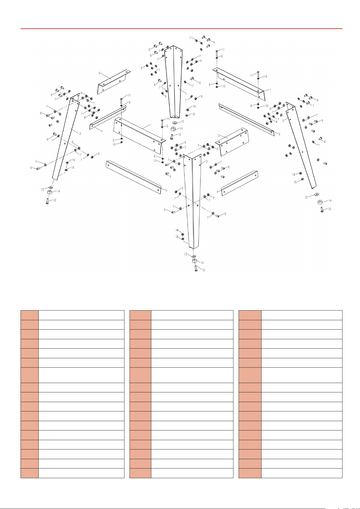
Stand (Diagram C)
EXPLODED DIAGRAMSLISTS
AC1950B 10inch
No. Description
1 Upper long bracket
2 Stand leg
3 Upper short bracket
4 Lower short bracket
5 Lower long bracket
6 Hex.socket pan head screw
M6X16
7 Washer 8
8 Washer 6
9 Hex.nut M8
10 Hex.nut M6
11 Hex.bolt M6X35
12 Hex.bolt M8X30
13 Gasket nut
14 Rubber mat
15 Washer 8
16 Hex.nut M8
(343C-C)
AC2305B 12inch
No. Description
1 Upper long bracket
2 Stand leg
3 Upper short bracket
4 Lower short bracket
5 Lower long bracket
6 Hex.socket pan head screw
M8X16
7 Washer 8
8 Hex.nut M8
9 Hex.nut M8
10 Washer 8
11 Hex.bolt M8X40
12 Hex.bolt M8X30
13 Gasket nut
14 Rubber mat
15 Washer 8
16 Hex.nut M8
(343B-C) (3425-C)
AC2606B 14inch
No. Description
1 Upper long bracket
2 Stand leg
3 Upper short bracket
4 Lower short bracket
5 Lower long bracket
6 Hex.socket pan head screw
M8X16
7 Washer 8
8 Hex.nut M8
9 Hex.nut M8
10 Washer 8
11 Hex.bolt M8X40
12 Hex.bolt M8X30
13 Gasket nut
14 Rubber mat
15 Washer 8
16 Hex.nut M8
43
Page 44
The Axminster guarantee
Buy with confidence from Axminster!
So sure are we of the quality, we cover all parts and labour free of charge for three years!
For more information visit axminstertools.com/3years
The packaging is suitable for recycling.
Please dispose of it in a responsible manner.
EU Countries Only
Do not dispose of electric tools together with household waste material.
By law they must be collected and recycled separately.
Axminster Tools, Axminster Devon EX13 5PH
axminstertools.com
 Loading...