

Page 1
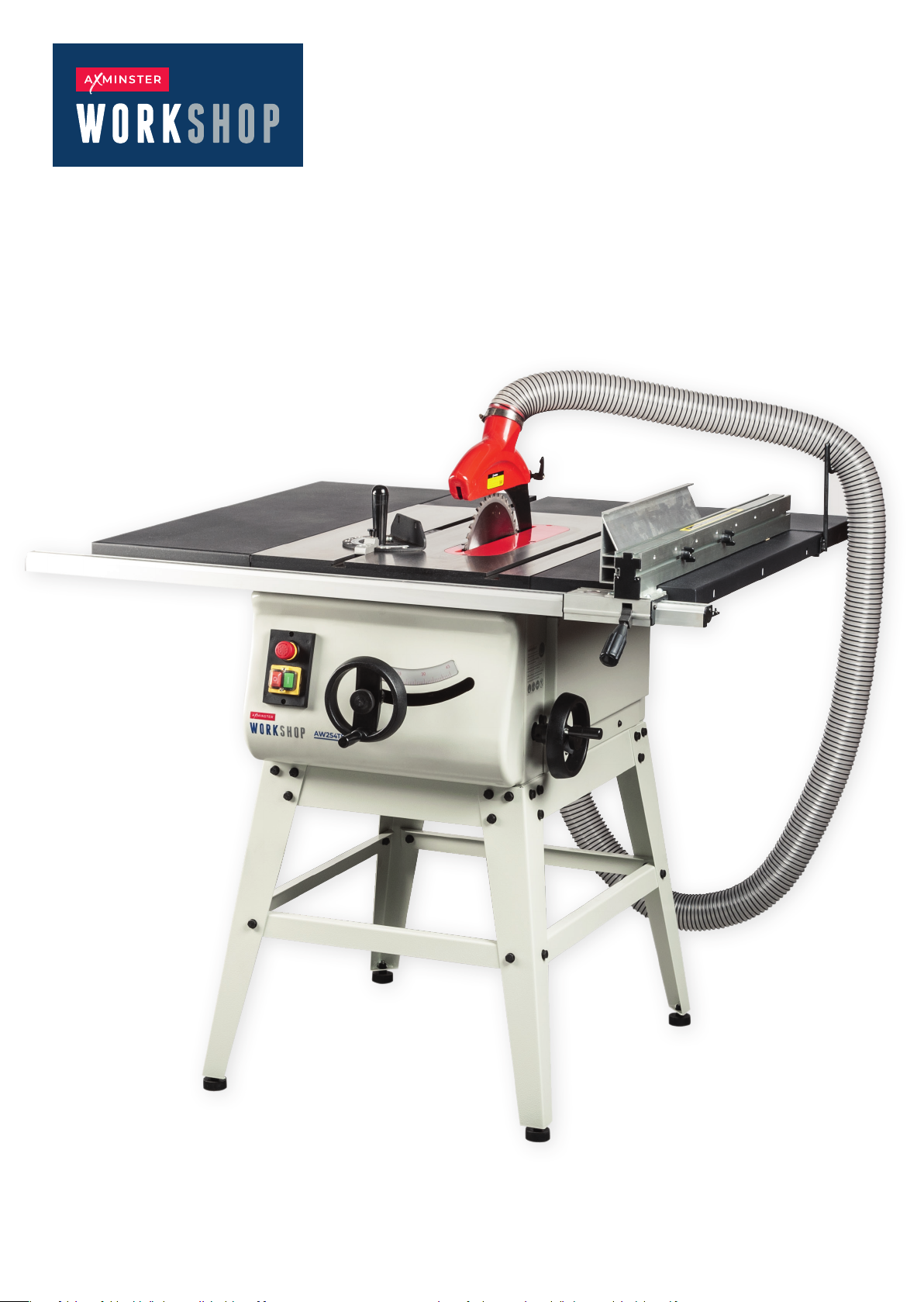
AW254TS
Table Saw
Code 111810
Original Instructions
AT: 31/07/2025
BOOK VERSION: 2
Page 2
INDEX OF CONTENTS
EU Declaration of Conformity 2
What’s Included 3
General Instructions for 230V Machines 4
Specic Instructions for Table Saws 5
Specication 6
Assembly 6
Assembly Floor Stand 10
Illustration and Parts Description 11
Set Up and Adjustment 14
Operating Instructions 18
Changing the Saw Blade 19
Maintenance 20
Exploded Diagrams/Lists 22
Wiring Diagram 25
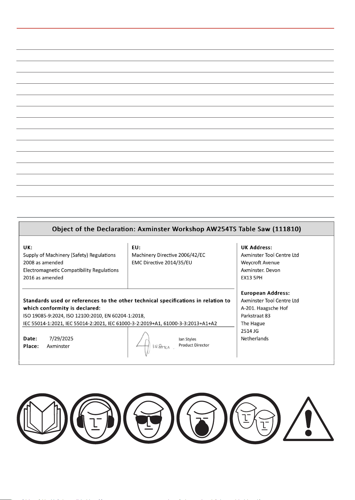
EU DECLARATION OF CONFORMITY
The symbols below advise the correct safety procedures when using this machine.
Fully read manual
and safety instructions
before use
Ear protection
should be worn
Eye protection
should be worn
2
Dust mask
should be worn
Two Man
Assembly
HAZARD
Page 3
WHAT’S INCLUDED
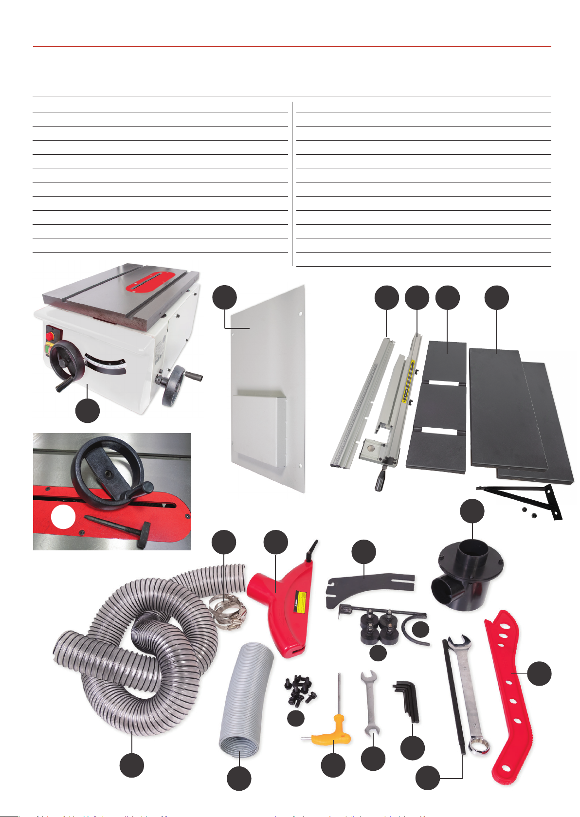
Quantity Item Part Model Number
AW254TS
1 Basic Table Saw A
2 Side Extension Tables plus supports B
1 Rear Extension Table C
2 Operating Wheels with Clamping Knobs D
1 Rip Fence Assembly E
1 Rip Fence Extension F
1 Rip Fence Rail with Scale G
1 Riving Knife H
1 Hose Support Bracket I
1 Dust Extraction Moulding J
1 Crown Guard with Clamping Handle K
1 Outer Flexible Hose L
4 Hose Clips M
1 Push Stick N
1 Blade Locking Bar O
1 24mm Spanner P
1 13-15mm Spanner Q
4 Hex Keys 6,5,3,2mm R
1 Handle Hex Key S
4 M8 Threaded Feet with nut/washer T
9 M8 Bolts, washers & one nut U
1 Inner Flexible Hose V
1 Base Plate W
D
A
W
M
K
H
EG
C B
J
L
V
3
U
S
I
T
N
R
Q
O
Page 4
GENERAL INSTRUCTIONS FOR 230V MACHINES
The following will enable you to observe good working
practices, keep yourself and fellow workers safe and maintain
your tools and equipment in good working order.
WARNING!! KEEP TOOLS AND EQUIPMENT
OUT OF REACH OF YOUNG CHILDREN
KEEP WORK AREA AS UNCLUTTERED AS IS PRACTICAL.
UNDER NO CIRCUMSTANCES SHOULD CHILDREN BE
ALLOWED IN WORK AREAS.
Mains Powered Tools
• Tools are supplied with an attached 13 Amp plug.
• Inspect the cable and plug to ensure that neither are
damaged. Repair if necessary by a suitably qualied person.
• D
o not use when or where it is liable to get wet.
Workplace
• Do not use 230V a.c. powered tools anywhere
within a site area that is ooded.
• Keep machine clean.
•
Leave machine unplugged until work is about to commence.
• Always disconnect by pulling on the plug body and not the
cable.
• Carry out a nal check e.g. check the cutting tool
is securely tightened in the machine and the correct
speed and function set.
• Ensure you are comfortable before you start work,
balanced, not reaching etc.
• Wear appropriate safety clothing, goggles, gloves,
masks etc. Wear ear defenders at all times.
• If you have long hair wear a hair net or helmet to prevent it
being caught up in the rotating parts of the machine.
• Consideration should be given to the removal of rings and
wristwatches.
•
Consideration should also be given to non-slip footwear etc.
• If another person is to use the machine, ensure they are
suitably qualied to use it.
Do not use the machine if you are tired or distracted
•
• Do not use this machine within the designated safety areas
of ammable liquid stores or in areas where there may be
volatile gases.
• Check cutters are correct type and size, are undamaged
and are kept clean and sharp, this will maintain their
operating performance and lessen the loading on the
machine.
• OBSERVE…. make sure you know what is happening
around you and USE YOUR COMMON SENSE.
4
Page 5
SPECIFIC INSTRUCTIONS FOR TABLE SAWS
Make sure the saw blade is the correct type for the job in hand.
Do not force the saw, if the saw begins to ‘stall’ you are ‘forcing
the cut’ or over working the saw.
Ensure that the saw blade is clean and sharp.
Resin build up on the blades will increase the friction of the
saw passing through the timber, and cause over heating of
the blade, blunt teeth will work harder tearing the bre of
the timber as opposed to shearing it, also with subsequent
overheating. Both faults unnecessarily load the machine
beyond normal usage, and shorten its longevity.
Do not use blades that are deformed in any way.
Do not remove the blade guard. The design of the riving knife
on the machine will not allow for slotting or ‘blind’ grooving,
so there is no reason to remove the guard.
FOR YOUR OWN SAFETY NEVER OPERATE
THE TABLE SAW WITHOUT THE RIVING KNIFE
IN PLACE!
Do not remove the riving knife.
Do not use any blades that cut a smaller kerf than the riving
knife thickness. Make sure the riving knife is correctly adjusted
to the blade and is securely fastened. If the table insert
becomes damaged or broken, and will not support the timber
‘up close’ to the blade, replace it.
After switching o, never try to slow the saw down more
quickly by applying side pressure (with a piece of wood?) to
the blade. Apply the old joiner’s adage of never getting hands
within one handbreadth of the blade. Leave the machine
disconnected from the mains supply until you are about to
commence work.
Always disconnect the machine if you are leaving it unattended.
Never leave the vicinity of the machine unless the blade has
come to a complete stop.
Do not attempt to carry out any maintenance, corrective work,
setting up etc., unless the machine is disconnected from the
mains supply. If any tools have been used during setting up
procedures, make sure they are removed from the machine
and stowed safely away.
USE THE SUPPLIED PUSH STICK
WHEN CUTTING SMALL PIECES.
Do not attempt to carry out cross cutting operations ‘freehand’,
always use the mitre fence for small stu and the sliding
carriage for larger work pieces. Do not attempt to ‘rip’ freehand,
always use the guiding facility of the rip fence.
It is perfectly acceptable to support guide and feed the timber
with your hands whilst ripping stu of some length, however,
as you approach the blade ensure that the push stick is to hand,
and you use it.
UNDER NO CIRCUMSTANCES SHOULD
CHILDREN BE ALLOWED IN THE WORK AREA
AND KEEP TOOLS AND EQUIPMENT OUT OF
REACH OF YOUNG CHILDREN!
CONNECT A DUST EXTRACTION
MACHINE TO THE SAW.
Do not start the saw with the work piece touching the blade.
Do not commence sawing until the blade has run up to full
speed.
Remember the emphasis of the ‘push’ should be between the
blade and the fence and close to the fence. Use your free hand
to support and guide the material on the oside of the saw
blade and at least 100mm away from it. If the timber does not
extend to at least 100mm to the oside of the saw blade,
the material possibly does not need guiding or supporting.
WARNING! IF THE SAW JAMS!
SWITCH OFF IMMEDIATELY.
Check that there are no foreign objects e.g. old nails, screws,
small stones etc embedded in the material you are about to
cut. If necessary take a wire brush to the timber before working.
5
Page 6
SPECIFICATION
Code 111810
Model AW254TS
Rating Workshop
Power 1.5 kW 50Hz 230V 1ph
Blade Dia/Bore 254 mm / 30 mm
Blade Tilt 0° to 45°
Blade RPM 3,000 rpm
T Slot Size 19 mm x 9.5 mm (3/4” x 3/8”)
Max Depth of Cut @ 45˚ 56 mm
ASSEMBLY
WARNING! THE SAW IS HEAVY SEEK
ASSISTANCE BEFORE LIFTING.
NOTE: If either sand or cabinet has been purchased,
assemble them rst, see page 12-13. Then mount the stand
to the saw before moving the saw and standing it upright.
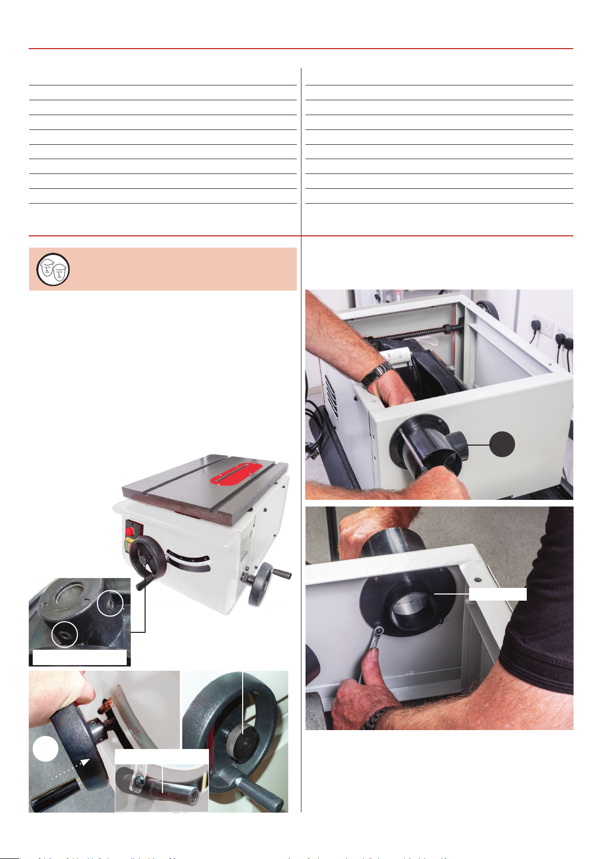
1. With assistance lift the saw assembly (A) from the box
onto a suitable work surface. loosen the two grub screws on
the operating wheels (D) and side each wheel onto the shafts.
Nip-up grub screws to securing in place, see g 01-02. Make
sure the screws clamp against the machined face on the shaft.
Insert the threaded locking knobs through the centre of
each operating wheel and nger tighten.
Max Depth of Cut @ 90˚ 80 mm
Max Width of Cut with Fence 430 mm with R/H Ext
Table Size 485 x 680 mm
Table Height 900mm
Table Size With Extensions 1060 x 900 mm
Dust Extraction Outlet 100 mm and 63 mm
Min Extraction Airow Required 1,000 m³/hr
Overall L x W x H 1,070 x 1,230 x 1,200 mm
Weight 109 kg
Fig 03-04-05
J
Fig 01-02
Grub screws
D
Machined face
Inner plate
Locking knob
2. Undo and remove the screws,washers & nuts to separate
the two parts of the dust extraction moulding (J). Position the
inner mounting plate over the machine cut out for the
extraction outlet. Repeat for the outer moulding, line up the
holes and replace the screws to secure the assembly (J) in
position, see g 03-04-05.
6
Page 7
ASSEMBLY
Fig 06-07
V
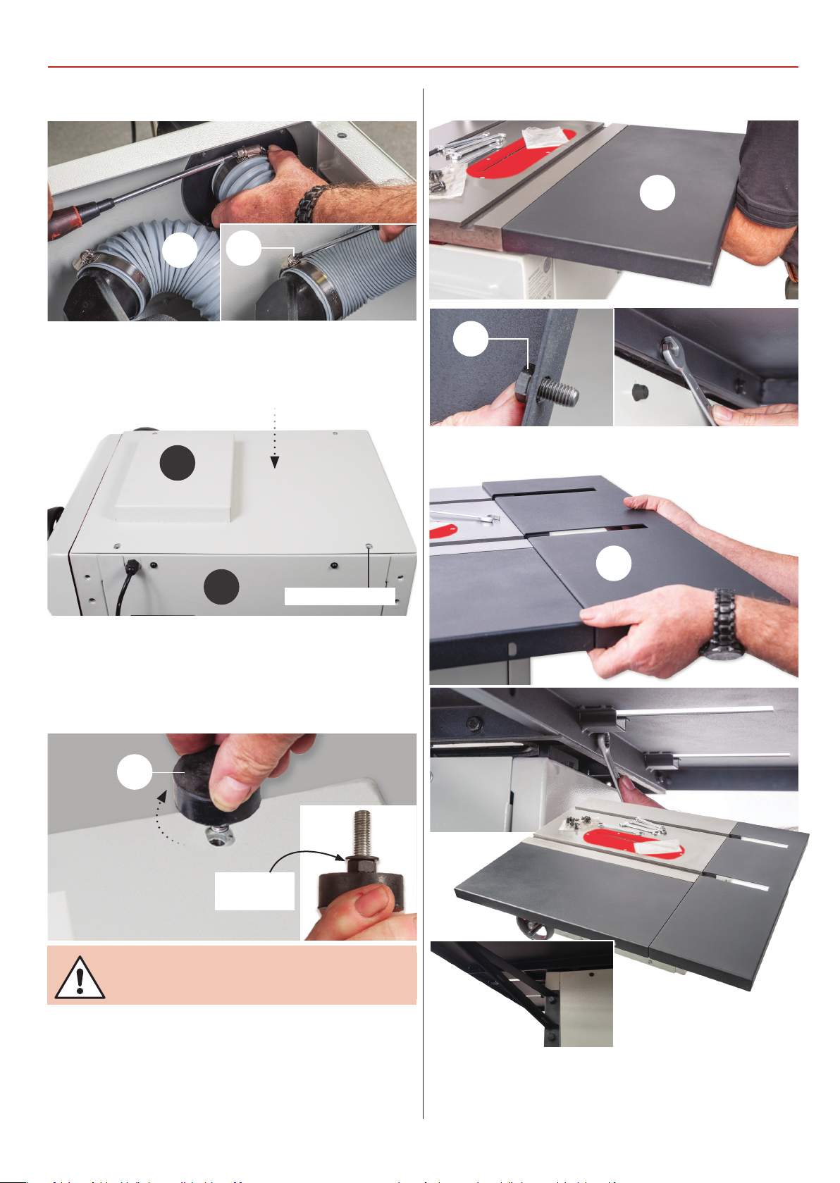
3. Locate the inner exible hose (V) and two hose clips (M).
Place a clip over each end of the hose and secure the hose over
the extraction outlets, see g 06-07.
M
Fig 08
W
Fig 10-11-12
B
U
Fig 13-14-15
A
4. Place the base plate (W) to the base of the saw (A) and
align the holes as shown in g 8. Find the four threaded feet (T),
screw each foot in turn into the threaded holes in each corner
of the chassis, see g 09 below. The feet will not be needed if
mounting to the leg stand.
Line up the holes
T
Locking nut &
washer
WITH ASSISTANCE TURN THE SAW
ASSEMBLY OVER!
5. Lower the saw down, locate the side and rear extension
tables (B-C) and M8 bolts/washers (U). Line up the holes in the
side extension table (B) with the threaded holes to the side
of the main cast iron table. Insert the bolts with washers (U)
through the holes and secure the extension table (B) to the
main cast iron table, see g 10-11-12.
7
C
Support arm
mounted to the
left hand rear saw
6. Repeat the procedure for the left & rear extension tables (C).
Note: make sure you line up the machined slots in the table
with the 19mm mitre ‘T’ slots in the cast iron table. Secure
both extension tables together, see g 13-14-15.
Continues over...
Page 8
ASSEMBLY
Fig 16-17
Insert plate
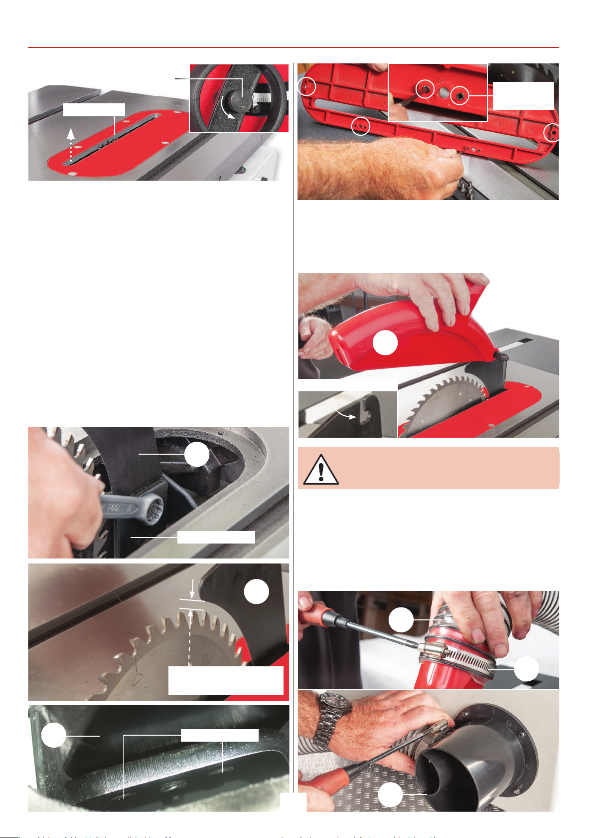
7. Raise the saw by rst releasing the rise & fall operating
wheel clamping knob, remove the ve cross head screws
holding the table insert and place safely aside, see 16-17.
Raise the saw to its maximum height by turning the
operating wheel anti-clockwise.
8. Find the riving knife (H) loosen the two nuts holding the
riving knife clamping plates, slide the riving knife down
between the two plates and lightly tighten to hold the riving
knife in place. Check that the tip of the knife has a clearance
of 3-8mm between the blade. Adjust the four grub screws to
the opposite side of the clamping plate to aline the riving
knife with the blade. Tighten the nuts to secure the riving
knife in place, see g18-19-20. Adjust the levelling grub
screws on the insert plate so it’s level with the main table,
see g 21. Re-secure the insert plate.
Clamping knob
Levelling
grub screws
9. Locate the crown guard (K), exible hose (L) and hose
clips (M). Loosen the lift & shift handle on the crown guard.
Introduce the slot to the rear of the crown guard (K) over the
riving knife and slot pin bolt into the curved slot in the riving
knife. Tighten the handle, see g 22.
Fig 22
K
Curved slot
Fig 18-19-20-21
H
Clamping plates
H
3-8mm Gap between the
riving knife and the blade
NOTE: DO NOT OVERTIGHTEN AS THE CROWN
GUARD IS PLASTIC AND COULD BE DAMAGED!
10. Locate the exible hose (L), place a hose clip (M) over one
end. Insert the hose over the extraction outlet on the crown
guard (K) and tighten the clip. Place the remaining clip over
the opposite end of the hose, insert the hose over the
extraction out moulding (J) and tighten, see g 23-24.
Fig 23-34
L
M
H
Grub screws
J
8
Page 9
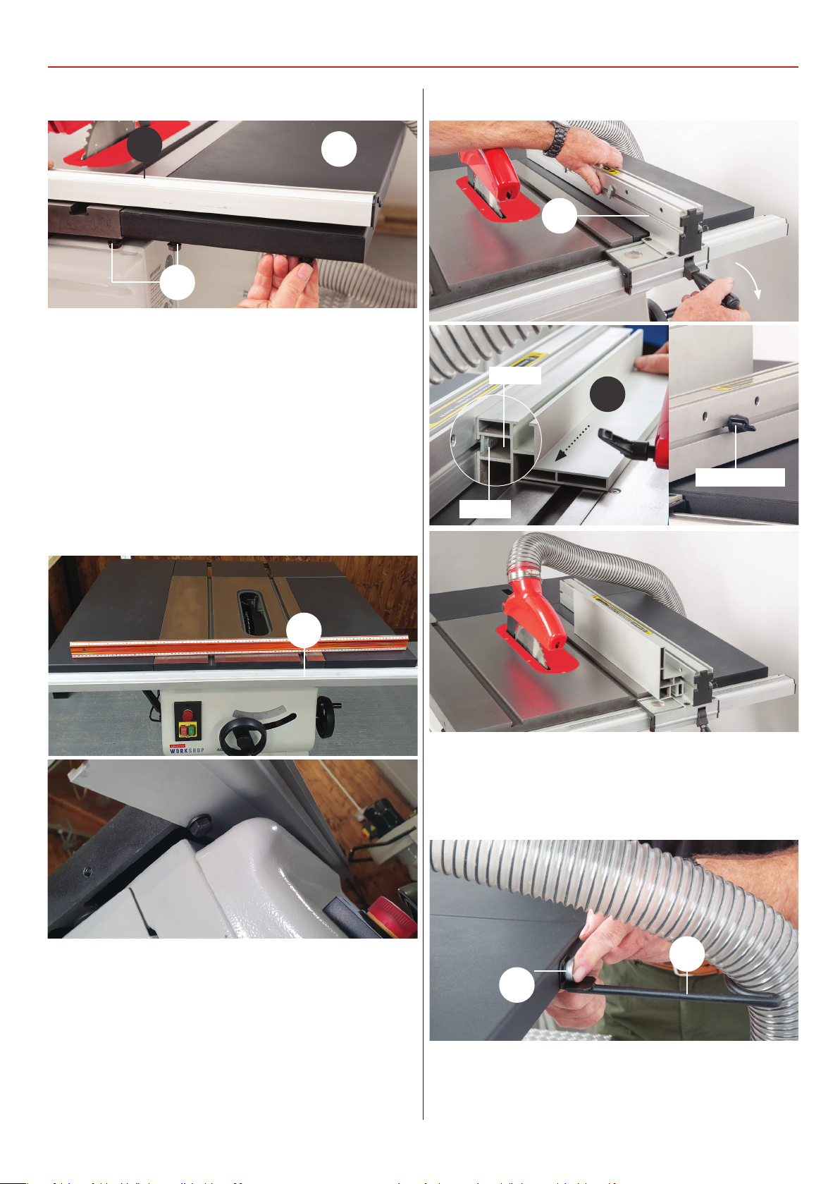
ASSEMBLY
Fig 35
G
B
U
11. Put to hand four M8 Bolts with washer/nuts (U) and rip
fence rail with scale (G). Insert two bolts with washers up
through the holes to the underside end of the side extension
table (B) and lightly screw on two bolts. Place the remaining
two bolts with washer into the threaded holes to the underside
of cast iron table, see g 35. Note: make sure to give enough
clearance between the tables and bolts for the next step.
12. Line up the machined slots in the rip fence rail (G) with the
bolts and slide the rail up against the tables. Nip up the bolts to
secure the rail, see g 36-37.
Fig 38-39-40
E
‘T’ Slot
F
Buttery knob
‘T’ bolt
Fig 36-37
G
15. Locate the hose support bracket (I) and secure it to the side
extension table (B) using a M8 bolt washer/nut (U). Insert the
holes (L) into the hose bracket, see g 41.
Fig 41
13. Locate the rip fence (E) and lower the clamp assembly
down over the fence rail (G) and press down the locking lever
to secure in position, see g 38.
14. Find the rip fence extension (F), slot the two ‘T’ bolts
mounted in the rip fence (E) into the ‘T’ slot on the fence
extension and nip up the buttery knob clamps, see g 39.
Note: the extension (F) can be set in two positions,
see g 40.
I
U
16. Place a straight edge across the tables and check they are
level and make adjustment until correct.
9
Continues over...
Page 10
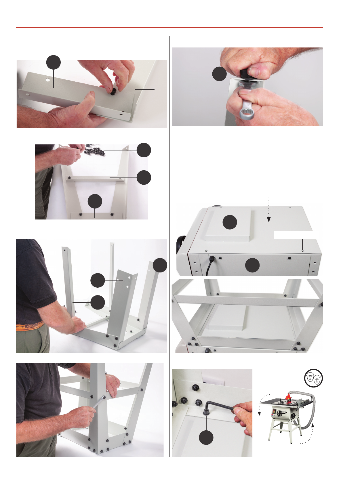
ASSEMBLY FLOOR STAND
Locate all the components on page 04 and assemble as follows.
Step 1
3
Step 2
7
5
3
Step 4
6
Mounting the Stand to the Saw
Remove the rip fence, crown guard and hose and lower saw
blade below the table. With assistance turn the saw assembly
(A) over & remove the four rubber feet (T). Place the base plate
(W) on top and align the holes as shown in step 5. Lower the
stand on top of the saw, line up the holes and secure using the
caphead bolts & washers (19). Place the assembly upright on
the oor, see step 6.
Step 5
Step 3
2
4
1
W
Line up the holes
A
Step 6
10
19
Page 11
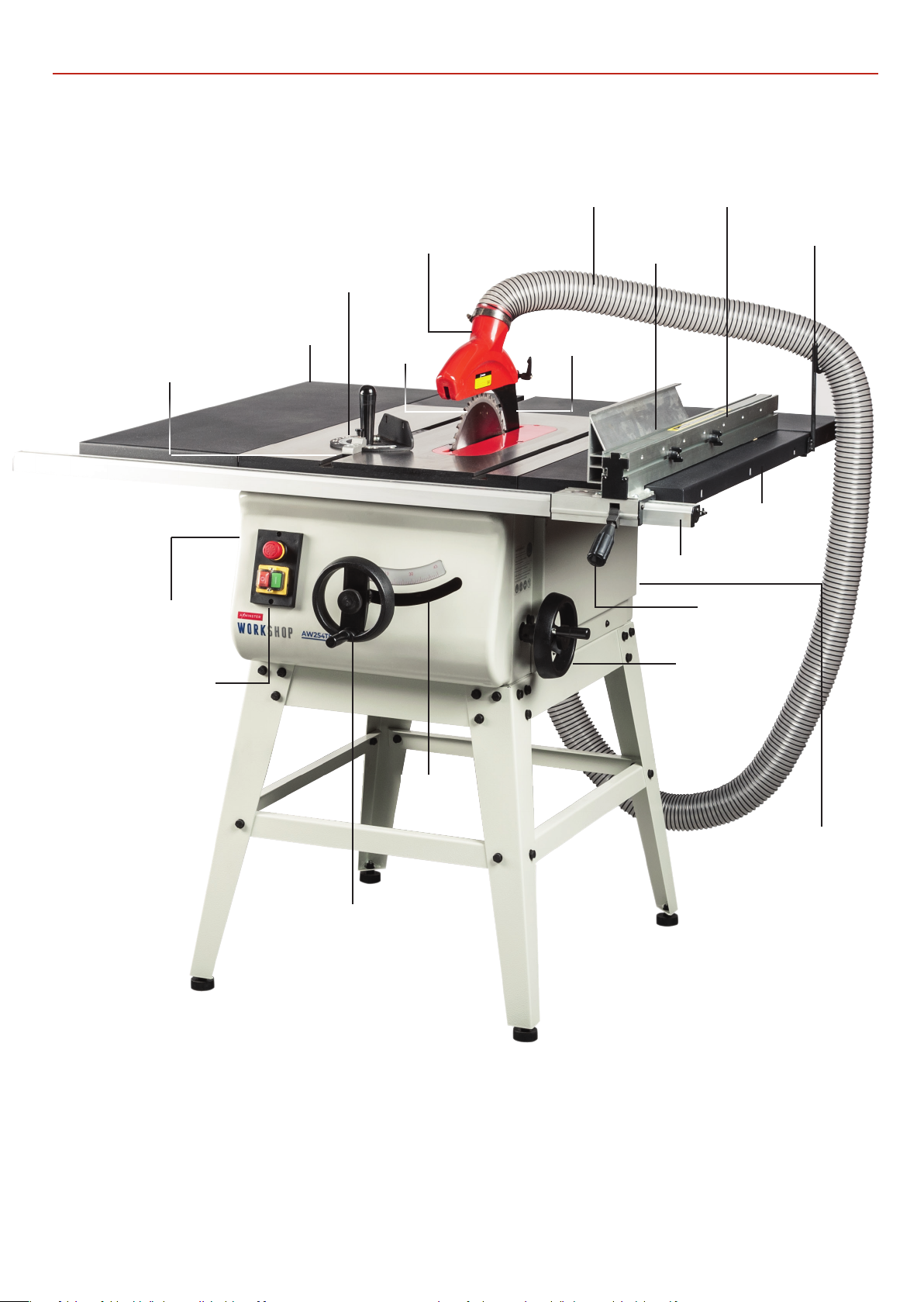
ILLUSTRATION AND PARTS DESCRIPTION
19mm ‘T ’ slots
Saw assembly
access panel
Cast iron table
Rear extension table
Crown guard
Saw blade
Flexible hose
Riving knife
Rip fence
extension
Rip fence rail
clamping handle
Rip fence
Hose support
bracket
Side extension
table
Rip fence
NVR Control panel
45˚ Operating
wheel
45˚ Scale
Saw assembly
access panel
Rise & fall operating handle
11
Page 12
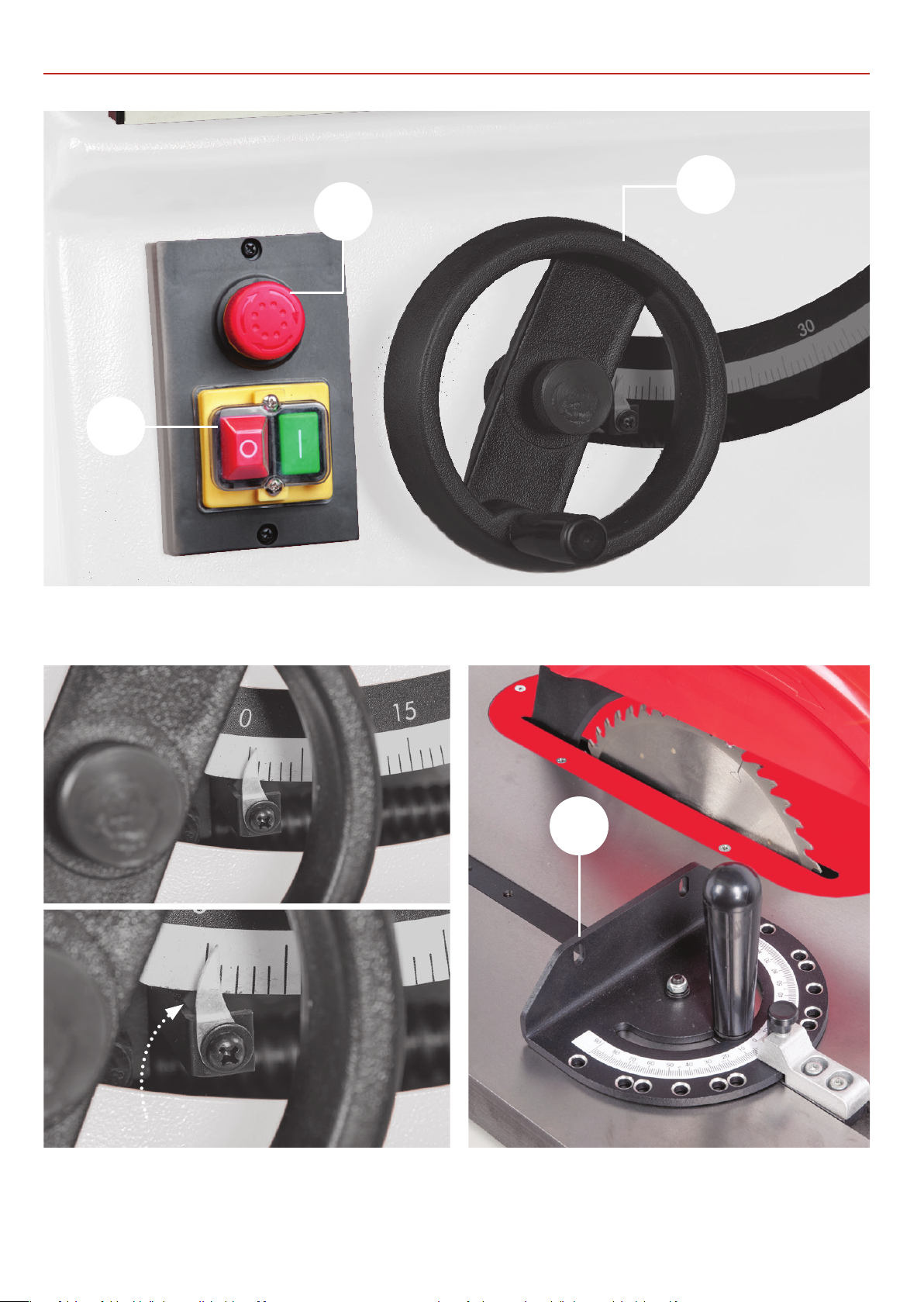
ILLUSTRATION AND PARTS DESCRIPTION
B
A
C
ON/OFF control switch (A), Emergency stop button (B)
Rise and Fall operating wheel (C)
32
Tilt scale pointer and adjusting screw Motor and saw assembly
12
Optional 104928 Mitre Fence
Page 13
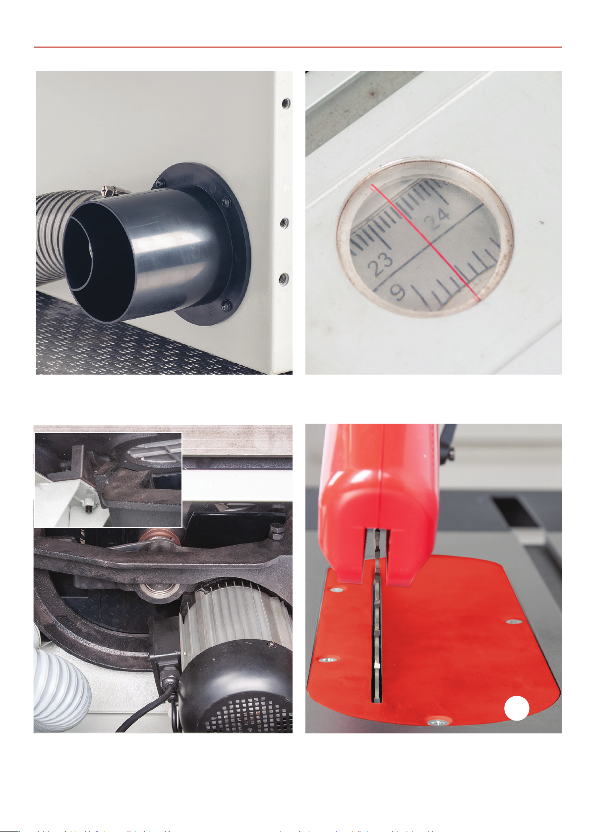
ILLUSTRATION AND PARTS DESCRIPTION
100mm Dust extraction moulding Rip fence magnifying glass
and index marker
Motor and saw assembly Optional 104933 insert gives
better material support for
cutting thin strips
13
31
Page 14
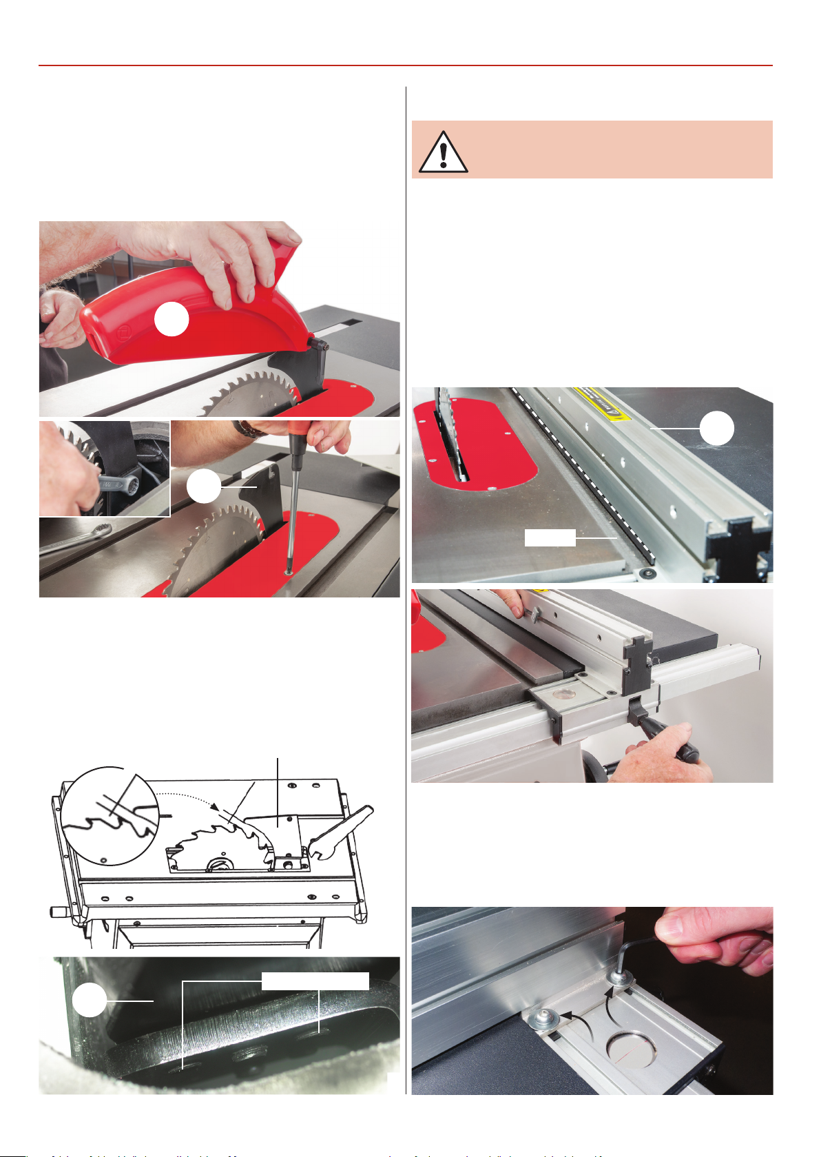
SET UP AND ADJUSTMENT
SET UP AND ADJUSTMENT
3. Place the fence assembly up against the blade and lock in
place, see fig 78.
4. Using a pencil draw a line on the fence rail to mark the
postion, see fig 79.
Fig 78
Fig 79
Fig 83-84
Fig 80-81-82
5. Use a steel rule or vernier measure the distance between the
pointer & pencil line, remove the fence assembly & mark the
second position on the fence rail, see figs 80-81-82.
6. Locate the scale strip and peal off the backing, line-up the
scale’s ‘Zero’ line with pencil line’s pointer and carefully stick
down the scale strip, see 83-84.
Vernier
Scale ‘Zero’ line
Pointer position
pencil mark
Pointer position
pencil mark
Pointer
Pencil line
The Riving Knife
1. Raise the saw blade to its highest point and remove the saw
blade crown guard (K) and the table insert, place safely aside,
see g 71-72.
Fig 71-72
K
H
Setting the Rip Fence & Scale
MAKESURE THE BLADE IS SQUARE TO THE
TABLE AND THE FENCE IS SQUARE TO THE
BLADE!
The fence scale does not come pre-mounted to the fence
rail and needs to be stuck in place. NOTE: Before sticking
the scale down make sure the table and fence assembly is
square to the blade. Follow the instruction below.
1. Remove the crown guard (K) and rip fence extension (F) and
‘T’ bolts and place safely aside. Line up the fence (E) with the
edge of the tables ’T’ slot and press down the locking handle,
see g 75-76.
Fig 75-76
E
2. Using the spanner loosen the riving knife (H) and check
that the tip of the knife has a clearance of 3-8mm between the
blade. Adjust the four grub screws to the opposite side of the
clamping plate to align the riving knife with the blade. Tighten
the nuts to secure the riving knife in place. NOTE: Check that
the riving knife is parallel to the saw blade by placing the
fence up against them, see g 73-74.
Fig 73-74
3-8mm
Riving knife (H)
‘T’ Slot
2. Check the fence is parallel with the ‘T’ slot, if adjustment is
required loosen the four Hex screws on either side of the fence
assembly and adjust the fence until it’s in line, see g 77,
re-tighten the Hex screws.
Fig 77
H
Grub screws
14
Page 15
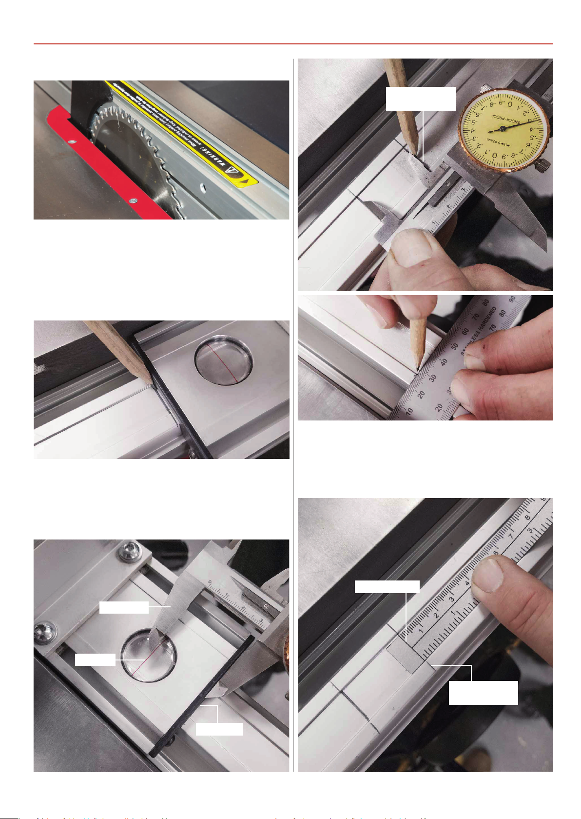
Fig 78
3. Place the fence assembly up against the blade and lock in
place, see fig 78.
4. Using a pencil draw a line on the fence rail to mark the
postion, see fig 79.
Fig 79
SET UP AND ADJUSTMENT
Pointer position
pencil mark
5. Use a steel rule or vernier measure the distance between the
pointer & pencil line, remove the fence assembly & mark the
second position on the fence rail, see figs 80-81-82.
Fig 80-81-82
Vernier
Pointer
6. Locate the scale strip and peal off the backing, line-up the
scale’s ‘Zero’ line with pencil line’s pointer and carefully stick
down the scale strip, see 83-84.
Fig 83-84
Scale ‘Zero’ line
Pointer position
pencil mark
Pencil line
15
Page 16
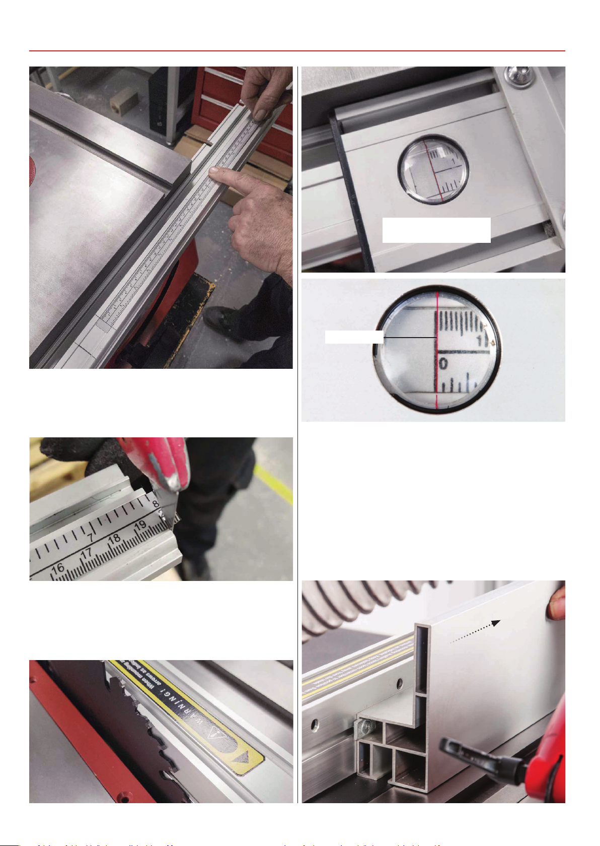
SET UP AND ADJUSTMENT
Magnifing Class Pointer
set to ‘ZERO’
7. Trim any excess material from the end of the fence rail, see
fig 85.
Fig 85
8. Replace the fence assembly and place against the blade. The
magnifying glass pointer should read ‘Zero’ on the fence rail
scale, see fig 86-87.
‘Zero’ pointer
Rip Fence Extension
The rip fence extension can be repositioned from the vertical
to a horizontal position for guiding thin pieces through. Loosen
the two butterfly knobs holding the fence extension, remove,
lay the fence extension down in the horizontal position and
remount the fence extension as before, see fig 89-90. Move
the extension down until the end face is centred with the
blade and tighten the two butterfly knobs.
Fig 89-90
Fig 86-87-88
16
Page 17
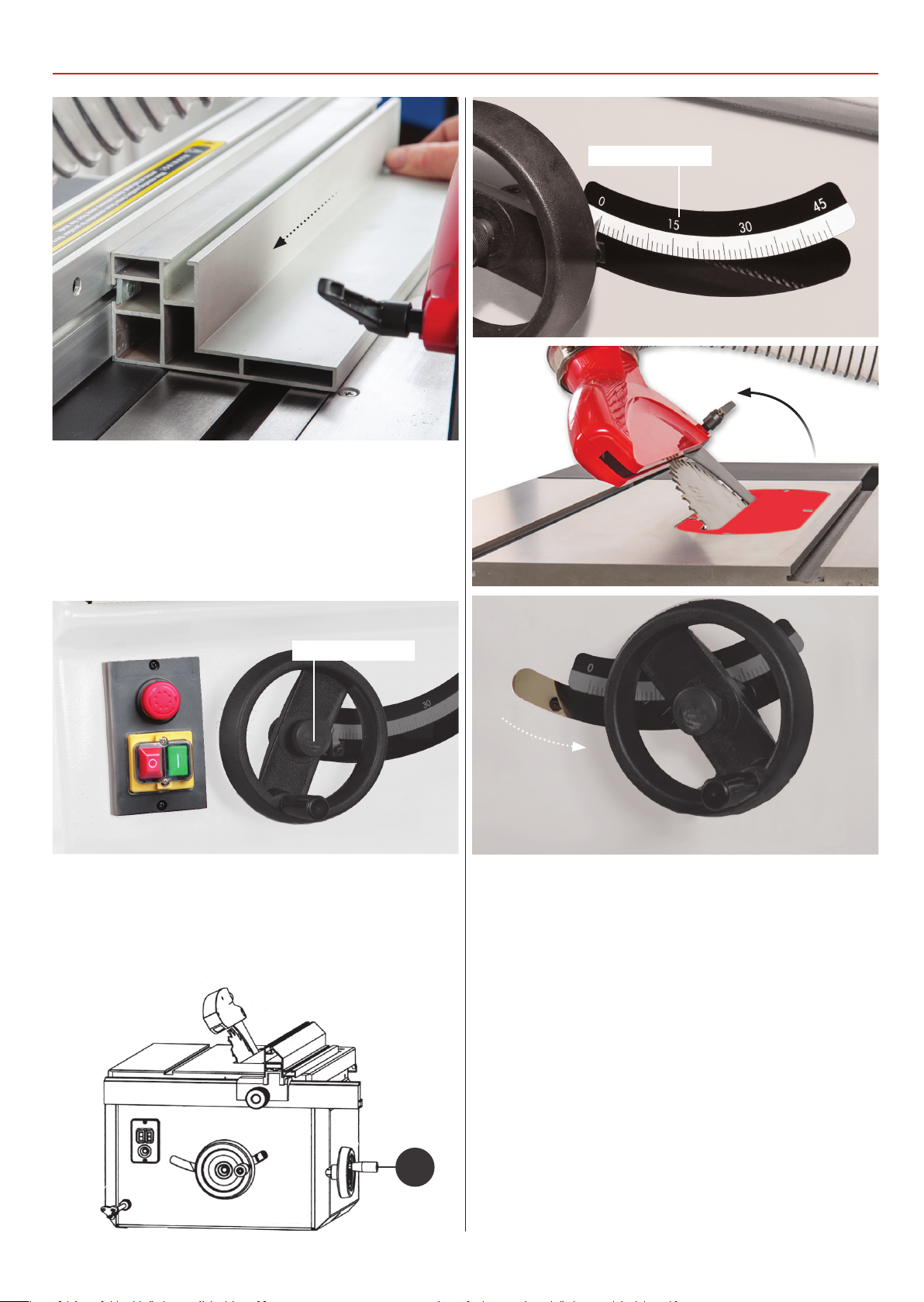
Adjusting the Cutting Height
Release the clamping knob, adjust the blade height with the
rise and fall operating wheel, see g 91, so that the blade teeth
are protruding through the work piece.
SET UP AND ADJUSTMENT
Saw pivot scale
45˚
Fig 91
Clamping knob
Adjusting the Pivot
Release the locking knob to the centre of the operating wheel
(a) to the side of the saw assembly and turn clockwise to pivot
the saw to a maximum of 45˚ degrees, indicated on the scale,
see g 92-93-94.
Fig 92-93-94
a
17
Page 18
OPERATING INSTRUCTIONS
NOTE: BEFORE USING YOUR SAW, GO
ROUND AND MAKE SURE EVERYTHING
IS SECURE, FASTENED DOWN, THAT ALL
TOOLS ARE CLEARED AWAY FROM THE
WORK AREA!
CHECK: THE BLADE FOR SHARPNESS,
MISSING TEETH, RESIN BUILD UP ETC.,
CLEAN IF NECESSARY. CHECK THE BLADE
IS SECURELY CLAMPED IN PLACE I.E. NOT
LOOSE!
CONNECT A DUST EXTRACTION
MACHINE TO THE SAW.
UNDER NO CIRCUMSTANCES SHOULD
CHILDREN BE ALLOWED IN THE WORK AREA
AND KEEP TOOLS AND EQUIPMENT OUT OF
REACH OF YOUNG CHILDREN!
N
NOTE: Secure larger pieces of timber to
the table by using the hold down clamp.
Cutting Narrow Pieces
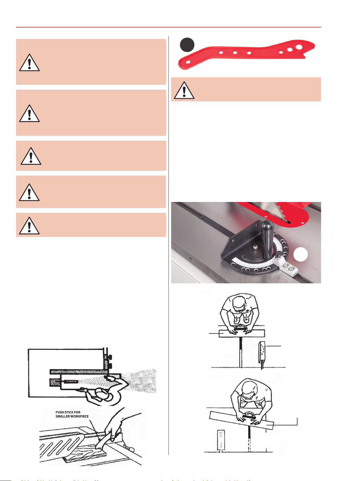
Use the small at surface of the rip fence extension (F) to cut
thin timber narrower that 120mm, note: use a push stick.
The Optional Mitre Fence
The mitre fence (32) can be mounted on either side of the saw
blade in the two 19mm ‘T’ slots, pre machined into the cast iron
table. The mitre fence can be angled from 90˚ to 45˚ degrees,
see g 98-99-100.
Fig 98-99-100
CONNECT THE SAW TO
THE MAINS SUPPLY!
Give the machine a ‘quick’ burst check ( i.e. quick ON-OFF) to
ensure everything is O.K. If everything is satisfactory, the table
saw is ready for use.
Feeding the Work by Hand
Start up the saw, wait until it has reached full speed and slowly
feed the timber through using both handles, (making sure to
keep your hands well clear of the blade and using a push stick
for small pieces), until the timber is behind the riving knife.
Switch o the saw, wait until the blade has come to a complete
stop and remove the timber, see g 95-96-97.
Fig 95-96-97
HOLD THE
WORK FIRMLY
32
THE BLADE IS SET
AT AN ANGLE
LESS THAN 90˚
DEGREES FOR
BEVEL CUTS
BLADE GUARD
18
LOCK THE MITRE
FENCE AND HOLD
THE WORK FIRMLY
Page 19
DISCONNECT THE MACHINE
FROM THE MAINS SUPPLY!
CHANGING THE SAW BLADE
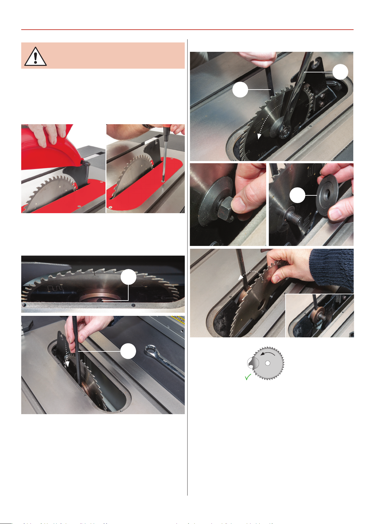
Fig 105-106-107-108
1. Raise the saw blade to its highest point, remove the saw
blade crown guard, remove the ve cross head screws that
secure the table insert, place carefully aside and remove the
table insert, see g 101-102.
Fig 101-102
2. Turn the saw until the locking bar hole (a) is visible and insert
the blade locking bar (O) into the hole, see g 103-104.
Fig 103-104
P
O
b
a
O
3. Hold the locking bar (O) undo and remove the nut using
the 24mm spanner (P), see g 105-106. Remove the saw plate
washer (b) and the saw blade and place to one side, see g
107-108.
Teeth forward
until nger tight and check the saw is correctly seated.
5. Tighten up the ‘Nut’, using the blade locking bar (O) to hold
the shaft steady. Check the riving knife is aligned with the saw
blade, and correctly positioned. Replace the table insert and
secure with the cross head screws. Replace the crown guard.
When everything is satisfactory, turn the saw blade once by
hand to check it doesn’t foul anywhere.
4. Give the interior of the machine, the dust extraction
channels, etc. a thorough clean. Check the new blade for
damage, missing teeth, sharpness etc. Fit the new blade, ensure
that the teeth are pointing towards the front of the machine.
Put the saw plate washer onto the shaft and replace the ‘Nut’
6. Reconnect the machine to the mains supply. Give the
machine a ‘quick’ burst (i.e. quick ON-OFF) check to ensure
everything is O.K. If everything is satisfactory, continue to use
the machine.
19
Page 20
MAINTENANCE
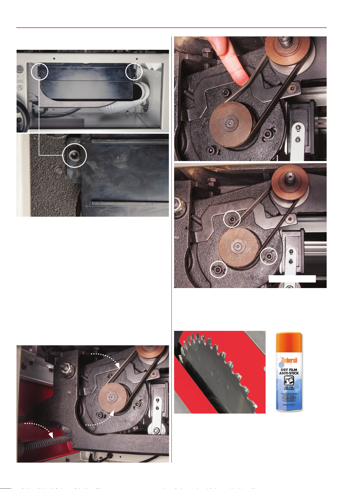
Fig 109-110
1. Keep the saw as clean and free from saw dust build up as is
practical. Periodically, remove the saw gullet by removing the
side access panel to the side of the machine and undo the two
Hex screws on either side of the gullet, see g 109-110. Vacuum
out and clean out the saw box and the extraction housing.
Remove any resin build up in the saw box, using a proprietary
resin cleaner.
2. Clean the threaded drive shafts of the rise and fall and tilt
mechanisms, see g 111. At the same time check the belt drive,
i.e. the belt is not ‘glazing’ with resin build up, likewise with
the pulley wheels. Check the belt tension, see g 112. If the belt
is becoming slack, loosen the motor Hex bolts and push the
motor down, see g 113. Re-tighten the Hex bolts.
Fig 111-112-113
Motor Hex bolts
3. Check the saw blade regularly for chipped, missing, damaged teeth etc. and remove any resin build up from the blade,
riving knife etc, see g 114.
Fig 114
4. If you have nished using the saw bench, clean above and
below the work table, wipe the saw bench over. If the saw is not
going to be used for a period of time, use ‘Ambersil Dry PTFE
Film Antistick’, spray, code 952137 over the work table, blade,
tilt and rise and fall screw threads and place a dust sheet over
the saw bench.
20
Page 21

21
Page 22
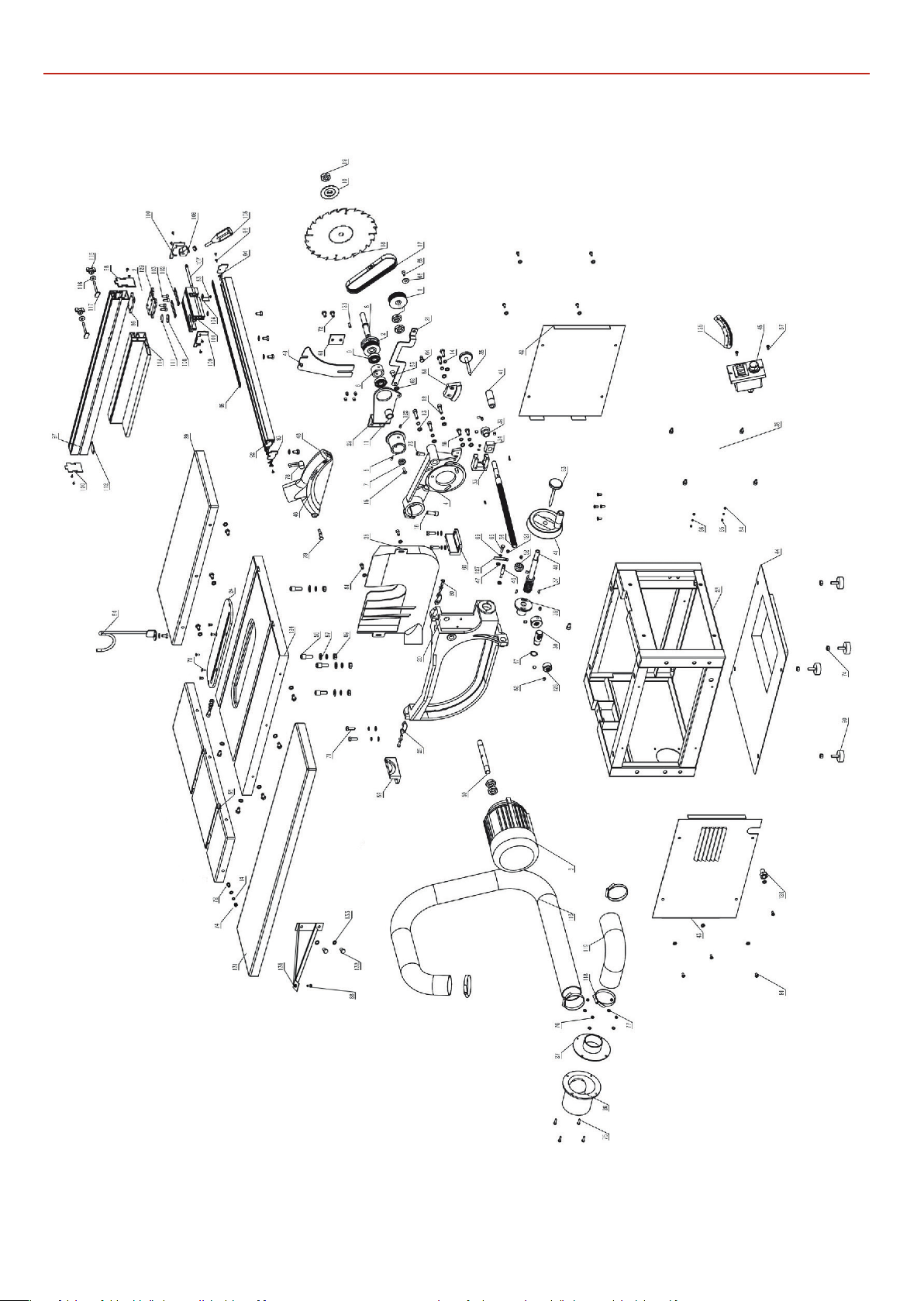
EXPLODED DIAGRAMS/LISTS
EXPLODED DIAGRAMS/LISTS
Diagram A
111810 Diagram A
22
Page 23
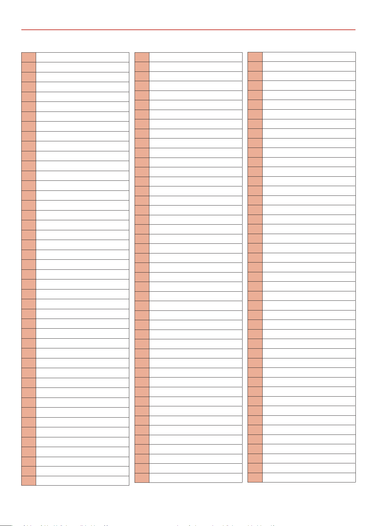
111810 Diagram A
EXPLODED DIAGRAMS/LISTS
No.
Description
1
Motor Pulley
2
Pulley
3
Motor
4
Shaft Base
5
Saw Blade Sleeve
6
Arbor Shaft Bush
7
End Bush of Arbor Shaft
8
Arbor Shaft
9
Bearing 6203
10
Outer BladeWasher
11
Arbor Shaft Bush
12
Hex.Socket Cap Head Bolt M8 x 30
13
Washer 8
14
SpringWasher 8
15
Cross Recessed Socket Screw M6 x 20
16
Hex.Socket Cap Head Bolt M10 x 30
17
Multi-Groove Belt
18
Saw Blade
19
M16 Nut
20
Rotating Bracket
21
Connection Rod of Riving Knife
22
Riving Knife Bracket
23
Machine Body
24
Table Insert
25
Rotating Block
26
Tie-in B
27
Tie-in A
28
Saw Blade Guard
29
Right Extension Table
30
Adjusting Thread Rod Nut
31
Stop Collar
32
Stop A
33
Mounting Seat A
34
Angel Connection Knob
35
Locking Knob A
36
Adjust Thread Rod
37
Semi-Circle Key 3 x16
38
Front Panel
39
Mounting Seat B
40
Height Adjusting Thread Rod
41 HandWheel
42 Right Panel
43 Left Panel
44 Bottom Panel
45 Switch
46 Pointer Block
47 Washer 6mm
48 Blade Guard
49 Riving Knife
50 Motor Shaft
51 Thin Nut M16 x1.5
52 Stop B
53 Locking Knob B
54 Tube Support
55 Rear Extension Table
56 Step Screw
57 BigWasher 10
58 Height Adjusting Gear
59 Mounting Base A
60 Mounting Base B
61 Pressing Plate Riving Knife
62 Washer 10
63 Hex.Recessed Socket Screw M8 x 20
64 Pull-Rod Shaft
65 Hex.Recessed Socket Screw M6 x 15
66 Motor Pad
67 Cir-Clips for Shaft D=20
68 Hex.Bolt M6 x 25
69 SpringWasher 6
70 Hex.Recessed Socket Screw M5 x 12
71 Hex.Bolt M8 x 25
72 Hex.Bolt M8 x 16
73 Hex.Socket Cap Head Screw M8 x 20
74 Hex.nut M8
75 Cross Recessed Pan Head Screw M5 x 20
76 Hex.Nut M5
77 Washer 5
78 Ratchet Lever
79 Bolt,blade guard
80 Cross Recessed Socket Screw M6 x 15
81 Hex.Socket Cap Head Screw M6 x 12
82 Hex.Socket Set Screw M8 x 8
83 Cross Recessed Pan Head Screw M4 x 6
84 Washer 4
85 Hex.Nut M4
86 SpringWasher 4
87 Cross Recessed Pan Head Screw M4 x 15
88 Hex.Bolt M8 x 20
89 Hex.Nut M10
90 Levelling Foot
91 Cross Recessed Pan Head Screw M6 x 12
92 Front Rail
93 Left End Cap Front Rail
94 Right End Cap Front Rail
95 Scale Front Rail
96 Taping Screw ST4.2 x 10
97 Rip Fence
98 Front End Cap Rip Fence
99 Screw Guide
100 Rear End Cap Rip Fence
101 Scale Rail Housing
102 Locking Nut Board
103 Hex.Socket Cap Head Bolt M6 x 16
104 Locking Spring Plate
105 Locking Knob
106 EccentricWheel
107 Locking Shaft
108 Scale Indicator
109 Left End Cap Scale Rail Housing
110 Right End Cap Scale Rail Housing
111 Circle Ring
112 Supporting Plate
113 Dust Collection Tube
114 Rip Fence
115 Wing Nut
116 BigWasher 6
117 Locking Screw
118 Neck Chain
Dust Collection Tube Inside The Machine Body
119
120 Cableland M14
121 Cross Recessed Pan Head Screw M5 x 8
122 Spring Pin 6
123 Key 5 x 20
124 Worktable
125 Scale Table Rotation
126 Hex.Socket Cap Head Bolt M8 x 16
128 Pointer
129 Stop Collar
130 Fence Plate
131 Left Extension Table
132 Hex.Bolt M8 x 20
133 Washer 12
134 Left Extension Table Support
23
Continues over...
Page 24
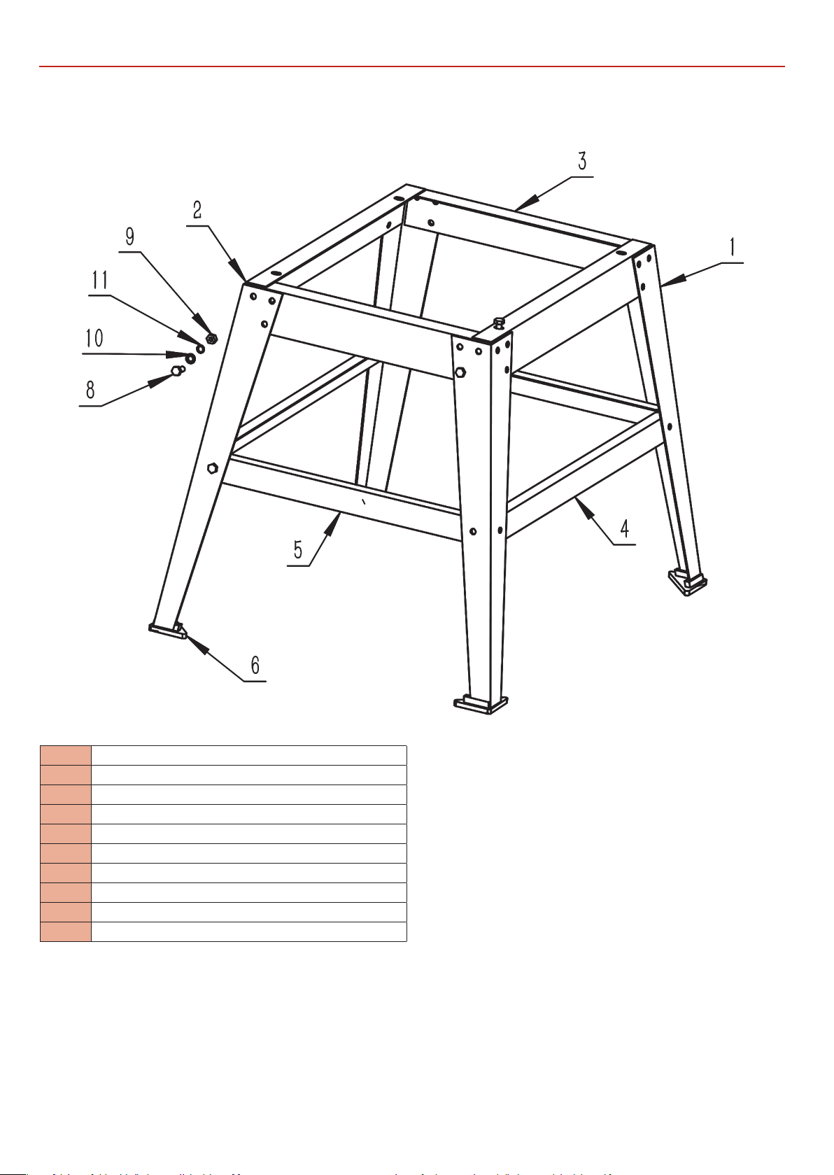
EXPLODED DIAGRAMS/LISTS
Floor Stand Diagram B
No. Description
1 Stand Leg
2 Upper Long Bracket Stand Leg
3 Upper Short Bracket Stand Leg
4 Lower Long Bracket Stand Leg
5 Lower Short Bracket Stand Leg
6 Levelling Foot
8 Hex.Nut M8
9 Washer 8mm
10 Hex.Bolt M8 x 16
24
Page 25
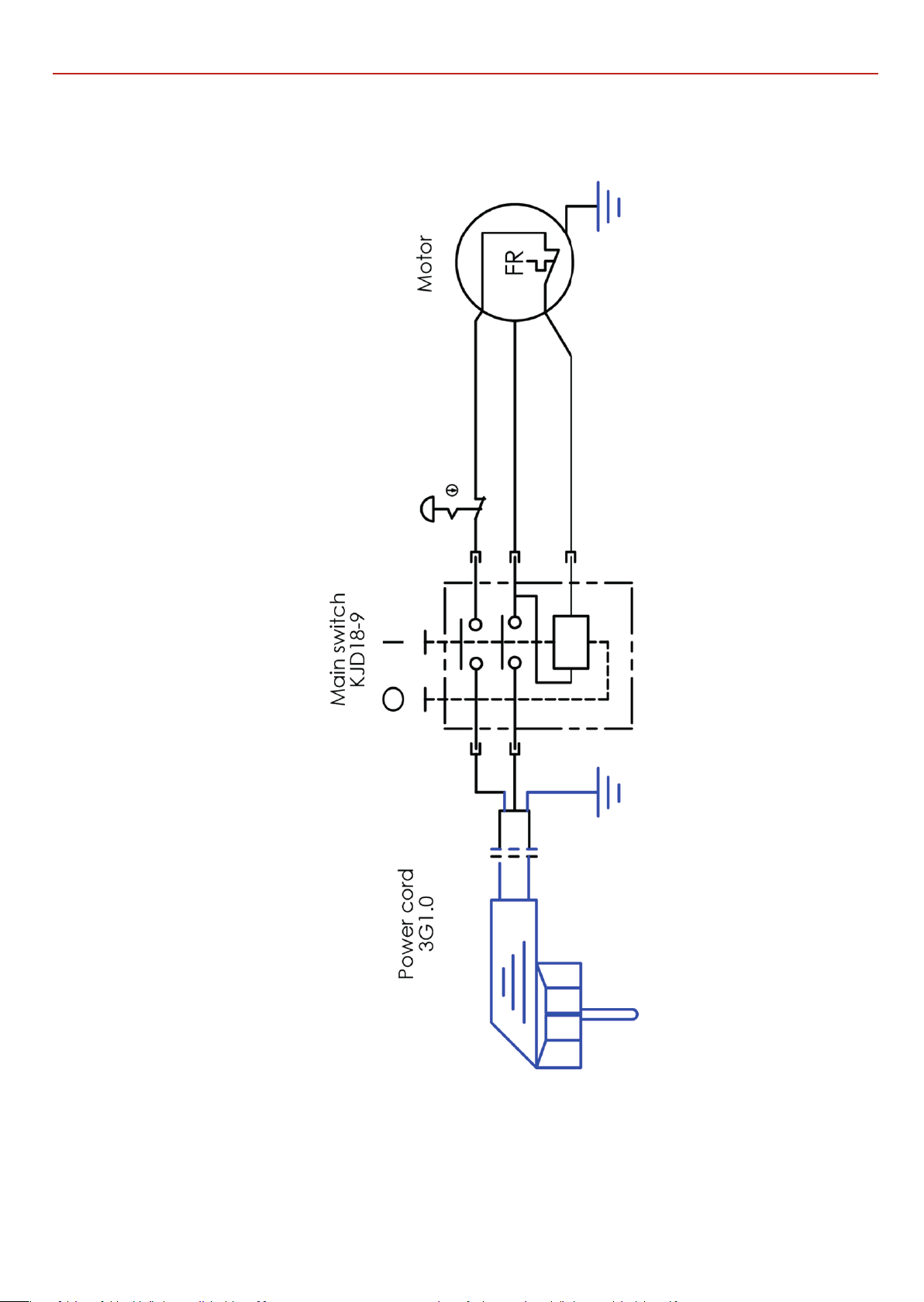
WIRING DIAGRAM
25
Page 26

26 27
Page 27

Page 28

Axminster Tools, Axminster Devon EX13 5PH
axminstertools.com
The packaging is suitable for recycling.
Please dispose of it in a responsible manner.
Do not dispose of electric tools together with household waste material.
By law they must be collected and recycled separately.
EU Countries Only
 Loading...