

Page 1
AW18BDS
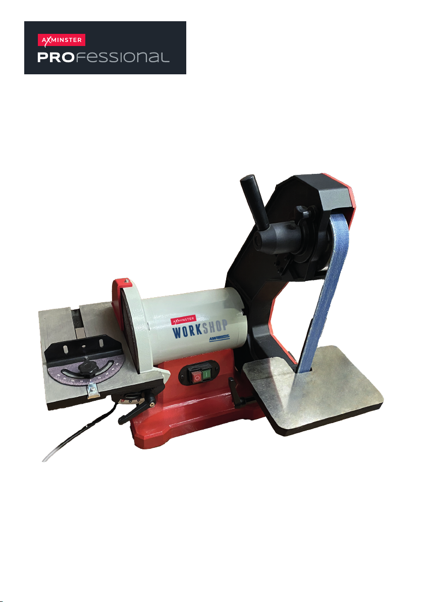
Belt Disc Sander
Code 111998
Original Instructions
AT20/12/2024
BOOK VERSION: 1
Page 2
Table of Contents
TABLE OF CONTENTS
Table of contents
Safety guidelines
Package contents
Key parts diagram
Assembly instructions
Operating instructions
Maintenance
Troubleshooting
Exploded view
Part list
Conformity Certicates 20
SPECIFICATIONS
2
3
9
10
11
13
15
17
18
19
Motor 230-240V/50Hz, 550W
Speed (no load) 2980 RPM
Belt size 25x1067mm
Belt speed 14m/s
Disc size 200mm
Disc speed 2980RPM
Dust port size
38.5mm
2
Page 3

3
SAFETY GUIDELINES
SAFETY GUIDELINES - DEFINITIONS
Safety Guidelines
• Always wear safety goggles or safety glasses with side shields.
• Always wear respiratory and hearing protection.
• To reduce the risk of injury, user and all bystanders must read and understand
instruction manual before using this product.
• Failure to keep your hands away from the moving part and cutting surface will
result in serious personal injury.
• No children or pregnant women should enter the work area where the paint
sanding is being done until all clean up is completed.
• A dust mask or respirator should be worn by all persons entering the work area.
The filter should be replaced daily or whenever the wearer has difficulty breathing.
•
NO EATING, DRINKING or SMOKING should be done in the work area to prevent
ingesting contaminated paint particles. Workers should wash and clean up BEFORE
eating, drinking or smoking. Articles of food, drink, or smoking should not be left in
the work area where dust would settle on them.
• Paint should be removed in such a manner as to minimize the amount of dust
generated.
• Areas where paint removal is occurring should be sealed with plastic sheeting
of 4 miles thickness.
• Sanding should be done in a manner to reduce tracking of paint dust outside the
work area.
• All surfaces in the work area should be vacuumed and thoroughly cleaned daily
for the duration of the sanding project. Vacuum filter bags should be changed
frequently.
• Plastic drop cloths should be gathered up and disposed of along with any dust
chips or other removal debris. They should be placed in sealed refuse receptacles
and disposed of through regular trash pick-up procedures. During clean up,
children and pregnant women should be kept away from the immediate work area.
• All toys, washable furniture and utensils used by children should be washed
thoroughly before being used again.
!
WARNING!
Use of this tool can generate and/or disperse dust, which may cause serious
and permanent respiratory or other injury. Always use NIOSH/OSHA approved
respiratory protection appropriate for the dust exposure. Direct particles away
from face and body.
3
Page 4

Safety Guidelines
POWER TOOL SAFETY
1. READ and become familiar with the entire Instruction Manual. LEARN the
tool’s application, limitations and possible hazards.
2. KEEP GUARDS IN PLACE and in working order.
3.
REMOVE ADJUSTING KEYS AND WRENCHES. Form the habit of checking
to see that keys and adjusting wrenches are removed from the tool before
turning ON.
4. KEEP WORK AREA CLEAN. Cluttered areas and benches invite accidents.
5. DO NOT USE IN DANGEROUS ENVIRONMENTS. Do not use power tools
in damp locations, or expose them to rain or snow. Keep work area well lit.
6. KEEP CHILDREN AWAY. All visitors and bystanders should be kept a safe
distance from work area.
7. MAKE WORKSHOP CHILD PROOF with padlocks, master switches or by
removing starter keys.
8. DO NOT FORCE THE TOOL. It will do the job better
and safer at the rate
for which it was designed.
9. USE THE RIGHT TOOL. Do not force the tool or an attachment to do a job
for which it was not designed.
10. USE PROPER EXTENSION CORDS. Make sure your extension cord is in
good condition. When using an extension cord, be sure to use one heavy
enough to carry the current your product will draw. An undersized cord will
result in a drop in line voltage and in loss of power which will cause the tool
to overheat. The table on page 8 shows the correct size to use depending
on cord length and nameplate ampere rating. If in doubt, use the next heavier
gauge. The smaller the gauge number, the heavier the cord.
11. WEAR PROPER APPAREL. Do not wear loose clothing, gloves, neckties,
rings, bracelets or other jewelry which may get caught in moving parts.
Nonslip footwear is recommended. Wear protective hair covering to contain
long hair.
12. ALWAYS WEAR EYE PROTECTION. Any power tool can throw foreign
objects into the eyes and could cause permanent eye damage. ALWAYS
wear Safety Goggles (not glasses) that comply with ANSI Safety standard
Z87.1. Everyday eyeglasses have only impact–resistant lenses. They ARE
NOT safety glasses. NOTE: Glasses or goggles not in compliance with ANSI
Z87.1 could seriously injure you when they break.
13. WEAR A FACE MASK OR DUST MASK. Sanding operation produces dust.
14. SECURE WORK. Use clamps or a vise to hold work when practical. It is
safer than using your hand and it frees both hands to operate the tool.
15.
DISCONNECT TOOLS FROM POWER SOURCE before servicing, and when
changing accessories such as blades, bits and cutters.
16. REDUCE
THE RISK OF UNINTENTIONAL STARTING. Make sure switch
is in the OFF position before plugging the tool in.
4
Page 5

Safety Guidelines
5
SAFETY GUIDELINES
People with electronic devices, such as pacemakers, should consult their
physician(s) before using this product. Operation of electrical equipment in
close proximity to a heart pacemaker could cause interference or failure of
the pacemaker.
WARNING!
!
17. USE RECOMMENDED ACCESSORIES. Consult this Instruction Manual for
recommended accessories. The use of improper accessories may cause risk
of injury to yourself or others.
18. NEVER STAND ON THE TOOL. Serious injury could occur if the tool is tipped
or if the cutting tool is unintentionally contacted.
19. CHECK FOR DAMAGED PARTS. Before further use of the tool, a guard or
other part that is damaged should be carefully checked to determine that it will
operate properly and perform its intended function – check for alignment of
moving parts, binding of moving parts, breakage of parts, mounting and any
other conditions that may affect its operation. A guard or other part that is
damaged should be properly repaired or replaced.
20. NEVER LEAVE THE TOOL RUNNING UNATTENDED. TURN THE POWER
“OFF”. Do not walk away from a running tool until the blade comes to a complete
stop and the tool is unplugged from the power source.
21. DO NOT OVERREACH. Keep proper footing and balance at all times.
22.
MAINTAIN TOOLS WITH CARE. Keep tools sharp and clean for best and safest
performance. Follow instructions for lubricating and changing accessories.
23. DO NOT use power tool in presence of flammable liquids or gases.
24. DO NOT operate the tool if you are under the influence of any drugs, alcohol
or medication that could affect your ability to use the tool properly.
25.
Dust generated from certain materials can be hazardous to your health. Always
operate saw in well-ventilated area and provide for proper dust removal.
26. WEAR HEARING PROTECTION to reduce the risk of induced hearing loss.
5
Page 6

Safety Guidelines
POWER TOOL SAFETY
1. USE sander on horizontal surfaces only. Operating the sander when mounted
on non-horizontal surfaces might result in motor damage.
2. TO STOP it from tipping over or moving when in use, the sander must be
securely fastened to a bench top or supporting surface.
3. PLACE the sander so neither the user nor bystanders are forced to stand in
line with the abrasive belt or disc.
4.
MAKE SURE the sanding belt is installed in the correct direction. See directional
arrow on back of belt.
5. ALWAYS have the tracking adjusted properly so the belt does not run off the
pulleys.
6.
DO NOT USE sanding belts or discs that are damaged, torn or loose. Use only
correct size sanding belt and disc. Narrower belts uncover parts that could
trap fingers.
7. MAKE SURE there are no nails or foreign objects in the part of the workpiece
to be sanded.
8. ALWAYS HOLD the workpiece firmly when sanding. Keep hands away from
sanding belt or disc. Sand only one workpiece at a time.
9. ALWAYS HOLD the workpiece firmly on the table when using the disc sander
and when using the belt sander.
10. ALWAYS SAND ON THE DOWNWARD SIDE of the sanding disc when using
the disc sander. Sanding on the upward side of the disc could cause the
workpiece to fly out of position, resulting in injury.
11. ALWAYS maintain a minimum clearance of 1/16 in. (1.6 mm) or less between
the table or backstop and the sanding belt or disc.
12. DO NOT sand pieces of material that are too small to be safely supported.
13. KEEP fingers away from where the belt goes into the dust trap.
14. WHEN sanding a large workpiece, provide additional support at table height.
6
Page 7

Safety Guidelines
7
SAFETY GUIDELINES
IMPORTANT INFORMATION-Electrical
GROUNDING INSTRUCTIONS
All grounded, cord-connected machines: In the event of a malfunction or breakdown,
grounding provides a path of least resistance for electric current to reduce the risk of
electric shock. This machine is equipped with an electric cord having an equipment
grounding conductor and a grounding plug.
DANGER!
DO NOT EXPOSE THE MACHINE TO RAIN OR OPERATE THE MACHINE IN
DAMP LOCATIONS.
THIS MACHINE MUST BE GROUNDED WHILE IN USE TO PROTECT THE
OPERATOR FROM ELECTRIC SHOCK.
!
The plug must be plugged into a matching outlet that is properly installed and
grounded in accordance with all local codes and ordinances.
Do not modify the plug provided–if it will not fit the outlet, have the proper outlet
installed by a qualified electrician.
Improper connection of the equipment-grounding conductor can result in risk of
electric shock. The conductor
with or without yellow stripes is the equipment-grounding conductor. If repair or
replac emen t of the elect ri c cord or plug i s necessary, do not connect the
equipment-grounding conductor to a live
Check with a qualified electrician or service personnel if the grounding instructions
are not completely understood, or if in doubt as to whether the machine
grounded.
with insulation having an outer surface that is green
terminal.
is properly
7
Page 8

Safety Guidelines
Use only 3-wire extension cords that hav
matching 3-conductor receptacles that accept the machine’s plug, as shown in Fig. A.
Repair or replace damaged or worn cord immediately.
!
WARNING!
In all cases,make certain the receptacle in question is properly grounded.
If you are not sure,have a electrician check the receptacle.
e 3-pronged grounding type plugs and
8
Page 9
9
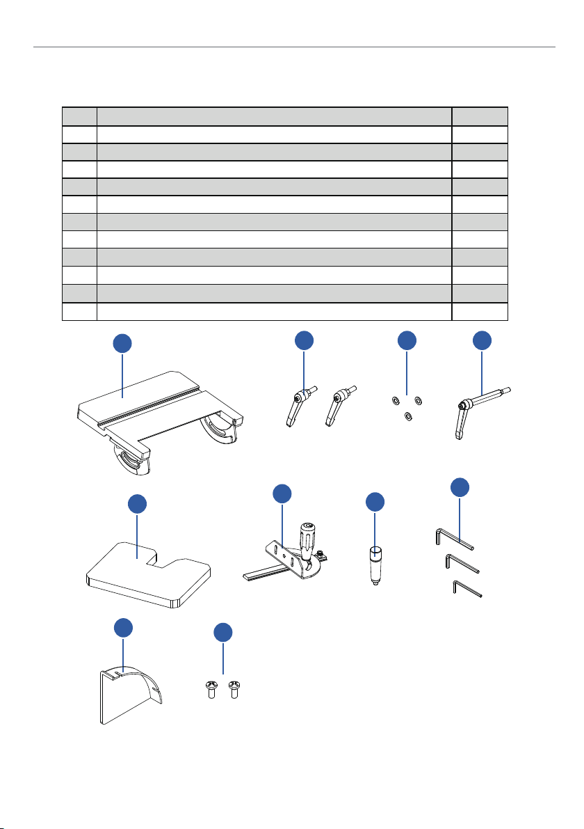
PACKAGE CONTENTS
Package contents
Packaging Contents
No. Description Qty.
Belt / disc sander (not shown) 1
1
Disc worktable
2
Disc table handle
3
4
Flat washer D8
Belt table handle 1
5
Belt worktable 1
6
Miter gauge assy 1
7
Belt tension handle 1
8
Inner hex wrench
9
Sanding disc cover
10
Philips screw
11
2
6
3 4 5
7
8
1
2
3
3
1
2
9
10
11
9
Page 10
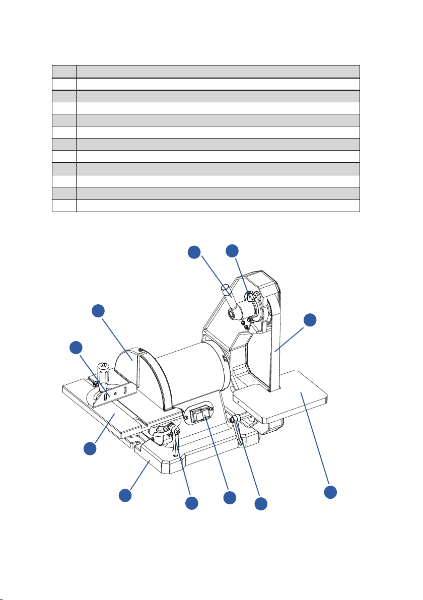
Key Parts Diagram
No. Description
8 in. diameter sanding disc
1
Miter gauge assy
2
Disc worktable
3
4
Base
Disc table handle
5
On / Off switch
6
Belt table handle
7
8
Belt worktable
1 in. width / 42 in. length sanding belt
9
Belt tracking knob
10
Belt tension handle
11
11
10
1
9
2
3
4
5
6
7
8
10
Page 11
Assembly Instructions
ASSEMBLY INSTRUCTIONS
11
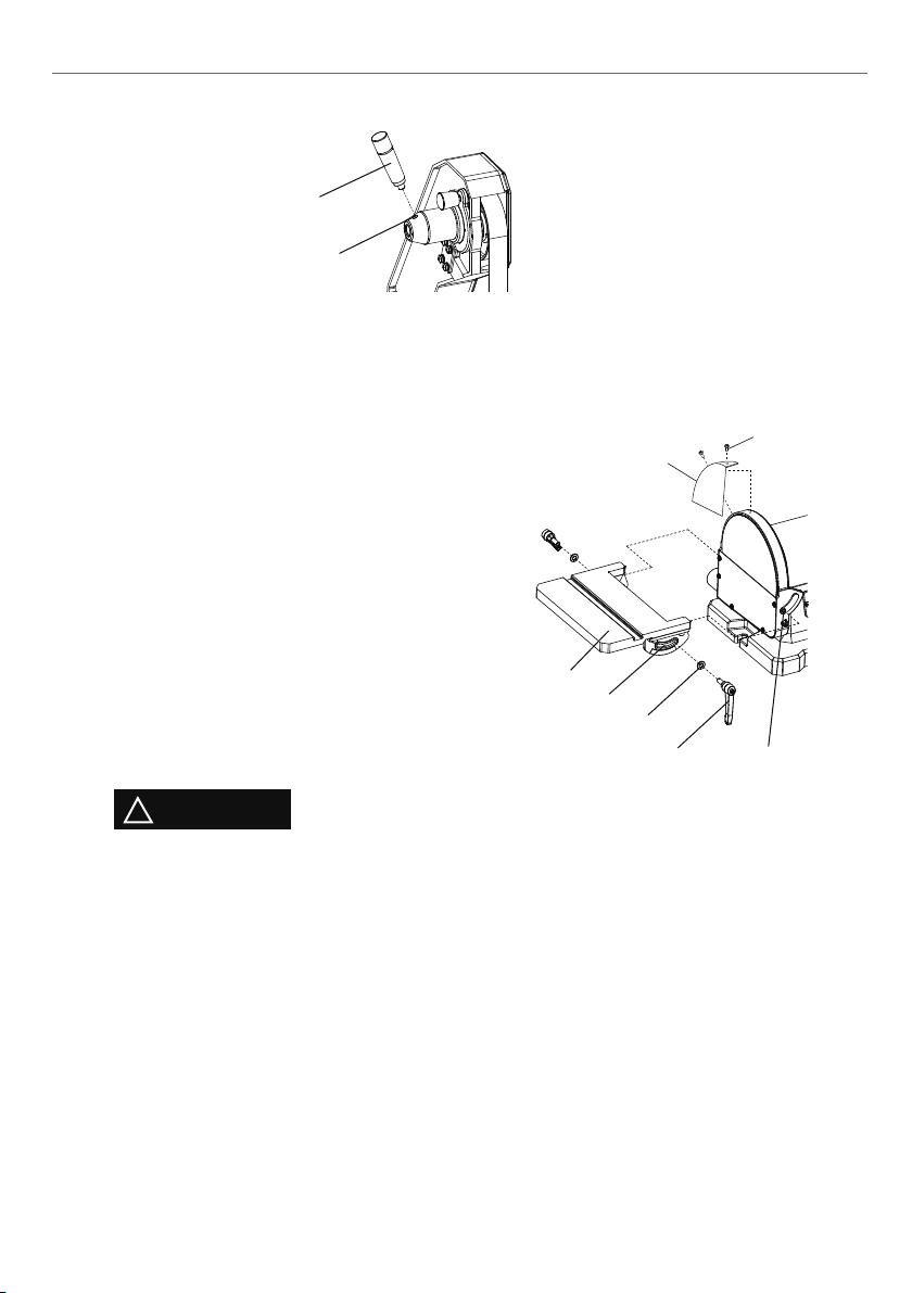
INSTALLING TENSION HANDLE
Screw the tension handle (1) into the hole (2) of the hub and lock it.
To avoid injury, always keep the plug disconnected from the power source and
the switch turned OFF until the sander is completely assembled and adjusted
properly.
WARNING!
!
1
MOUNTING WORKTABLE ON DISC
The larger worktable is used with the sanding disc. It should be used to support
workpieces in all sanding operations except inside curve applications.
1. Locate worktable handles (1) and washers
(2) in parts bag.
2. Place the worktable (3) onto the sander
frame, aligning the semi-circle slot (4) with
the threaded hole (5).
3. Place a washer (2) on threaded shaft of
each worktable handle (1), insert through
semi-circular slot (4), and tighten into
threaded hole (5). Repeat on other side of
table.
4. Adjust worktable to level or any angle
between 0° and 45° for sanding.
5. Mount the sanding disc cover (6) onto the
metal frame that surrounds the sanding
disc with the two Phillips Screws (7).
2
7
6
3
4
2
1
5
!
CAUTION
To avoid trapping the workpiece or fingers between the worktable and sanding
disc, the worktable edge should be positioned a maximum of 1/16 in. (1.6 mm)
from sanding disc plate.
Always sand on the downward, right side of the rotating disc.
11
Page 12
Assembly Instructions
The use of a dust collection system with the sander is strongly recommended.
prevent possible health hazards caused
The sander has two dust ports. Slide the hose of your dust collector over the outlet,
You can use it to attach two of your tools including your table saw, jointer, planer,
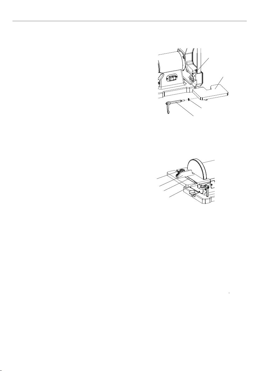
MOUNTING WORKTABLE ON BELT
1. Attach the belt work table (1) to the
4
sanding frame using a handle (2)
and flat washer (3) as shown.
1
NOTE: Ensure the locating pin (4) passes
through the table bracket and the registration
disc of the bracket is facing inwards.
3
2
MITER GAUGE
A miter gauge (1) is supplied with your sander and can be used with the sanding
table. The miter gauge body can be adjusted from 0° to 60° right or left for angle
or miter sanding.
1. Insert the miter gauge bar (2) into one end
of the miter slot (3) in the disc table.
2. Loosen lock knob (4) and then rotate
miter gauge body to the desired angle.
3. Tighten lock knob (4).
4
1
2
3
DUST COLLECTION
It will maintain shop cleanliness, and help
by wood dust.
and secure with a hose clamp.
Recommended (not included):
Search BUCKTOOL Y-fitting 4" to 1-3/8"(O.D.) Reducer
at AMAZON.COM or https://www.bucktool.com
bandsaw, disc sander, belt sander, drum sander, and more.
NOTE: Dryer vent hoses are not acceptable for this purpose.
12
Page 13
Operating Instructions
13
OPERATING INSTRUCTIONS
CAUTION
!
Always lock the switch off when the grinder is not in use. Remove the key
and keep it in a safe place. In the event of a power failure, blown fuse, or
tripped circuit breaker, turn the switch off and remove the key, preventing
an accidental startup when the power comes on.
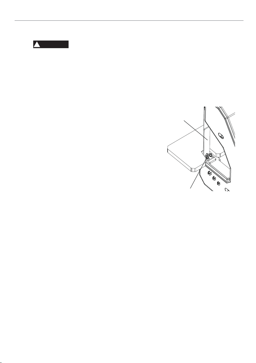
BELT PLATEN
The belt platen (1) is used to properly support
the workpiece while sanding. The platen (1) is
constructed of heavy steel to provide adequate
support.
The platen (1) should be adjusted so it is almost
touching the back of the abrasive belt. Loosen
the socket head cap screw (2) and adjust the
platen (1) to the desired position. Tighten the
screw (2) to secure the platen (1).
The platen can be removed for operations such
as stripping, contour sanding, polishing or other
special operations. To remove the platen,
remove the socket head cap screw and washer.
Note: Be sure to re-install the platen to perform
operations where support of the belt is required.
1
2
13
Page 14
Operating Instructions
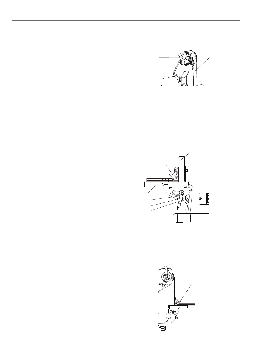
TO PROPERLY TRACK THE SANDING BELT
1. Plug in the sander.
2. Turn power switch ON, then immediately
OFF, noting whether the belt (1) tends to
slide off its track, and to which side of the
2
up
1
down
sander.
3. If the sanding belt does not slide to either
side, it is tracking properly.
4. Viewed from the switch end, if the sanding belt runs toward the disc side,
slightly turn the tracking knob (2) counterclockwise (up).
5. Viewed from the switch end, if the sanding belt runs away from the disc
side, slightly turn the tracking knob (2) clockwise (down).
6. Turn power switch ON, then immediately OFF again, again taking note of
any belt movement.
ADJUSTING DISC TABLE SQUARE WITH SANDING DISC
1. Using a combination square (1), place
one side of the square on the disc
table (2) with the other side against the
sanding disc (3), and check to see if the
disc table is 90° to the disc.
he disc table surface is not 90° to the
2. If t
disc, loosen the table lock knob (4), adjust
table square with disc and tighten the
table lock knob (4).
3. Loosen the screw (5) and secure the
scale pointer (6) at 0°.
1
2
4
6
5
3
NOTE: The disc table (2) can be tilted from 0° to 45° by loosening the table
lock knob (4). Tilt the disc table (2) to the desired angle. Tighten table
lock knob (4).
ADJUSTING BELT TABLE SQUARE WITH SANDING BELT
1. Using a combination square (1), place
one side of the square on the belt
table (2) with the other side against the
1
sanding belt (3), and check to see if the
disc table is 90° to the disc.
2. If the disc table surface is not 90° to the
disc, loosen the table lock knob (4), adjust
table square with belt and tighten the
table lock knob (4).
14
Page 15
Maintenance
15
MAINTENANCE
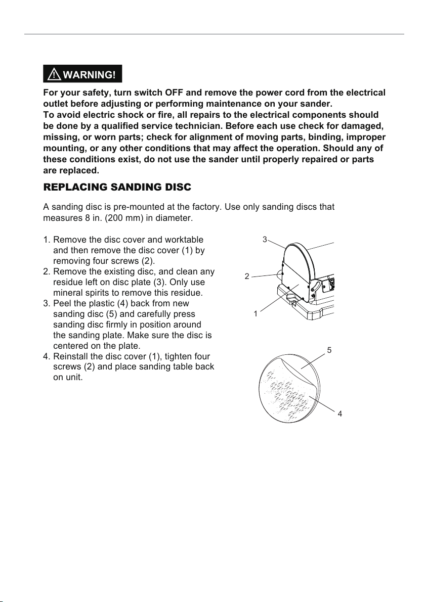
REPLACING SANDING DISC
A sanding disc is pre-mounted at the factory. Use only sanding discs that
measures 8 in. (200 mm) in diameter.
1. Remove the disc cover and worktable
and then remove the disc cover (1) by
removing four screws (2).
2. Remove the existing disc, and clean any
residue left on disc plate (3). Only use
mineral spirits to remove this residue.
3. Peel the plastic (4) back from new
sanding disc (5) and carefully press
sanding disc firmly in position around
the sanding plate. Make sure the disc is
centered on the plate.
4. Reinstall the disc cover (1), tighten four
screws (2) and place sanding table back
on unit.
For your safety, turn switch OFF and remove the power cord from the electrical
outlet before adjusting or performing maintenance on your sander.
To avoid electric shock or fire, all repairs to the electrical components should
be done by a qualified service technician. Before each use check for damaged,
missing, or worn parts; check for alignment of moving parts, binding, improper
mounting, or any other conditions that may affect the operation. Should any of
these conditions exist, do not use the sander until properly repaired or parts
are replaced.
WARNING!
!
1
2
3
5
4
15
Page 16
Maintenance
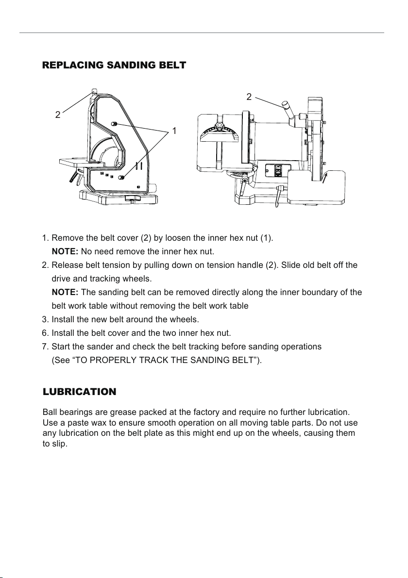
REPLACING SANDING BELT
1. Remove the belt cover (2) by loosen the inner hex nut (1).
NOTE: No need remove the inner hex nut.
2. Release belt tension by pulling down on tension handle (2). Slide old belt off the
drive and tracking wheels.
NOTE: The sanding belt can be removed directly along the inner boundary of the
belt work table without removing the belt work table
3. Install the new belt around the wheels.
6. Install the belt cover and the two inner hex nut.
7. Start the sander and check the belt tracking before sanding operations
(See “TO PROPERLY TRACK THE SANDING BELT”).
LUBRICATION
Ball bearings are grease packed at the factory and require no further lubrication.
Use a paste wax to ensure smooth operation on all moving table parts. Do not use
any lubrication on the belt plate as this might end up on the wheels, causing them
to slip.
1
2
2
16
Page 17
Troubleshooting Guide
17
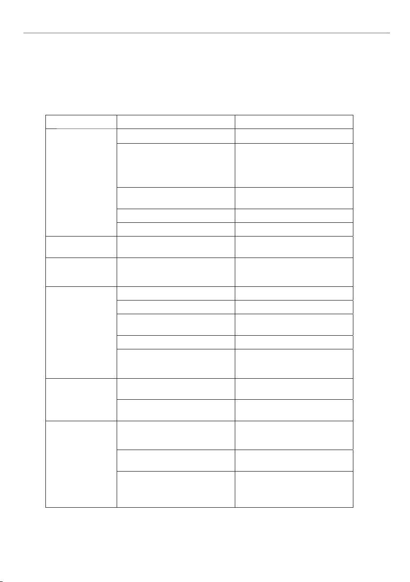
TROUBLESHOOTING GUIDE
WARNING!
To avoid injury from an accidental start, turn the switch OFF
and always remove the plug from the power source before
making any adjustments.
ydemeR esuaC elbaborP elbuorT
Not connected to power source. Connect to power source.
Determine reason for blown fuse/
Branch circuit fuse is blown or the
circuit breaker is tripped.
Sander will not start.
Voltage is too low.
Switch is defective. Replace switch.
Motor stalls easily. Low voltage.
Abrasive disc
separates from
aluminum disc.
Abrasive belt will not
track correctly.
Abrasive belt slips or
stalls when pressure
is applied.
Frequent
replacement of
abrasive belt or disc.
Improper bond.
Belt not centered on wheels. Readjust tracking.
Belt stretched unevenly. Replace abrasive belt.
Belt is jointed improperly.
Worn bearings.
Abrasive belt tension inadequate;
spring in tension mechanism is worn.
Excessive pressure being applied to
platen.
Too much pressure being applied to
workpiece.
Full width of belt or disc not being
used.
Incorrect abrasive material or grit
size.
tripped breaker (such as short circuit
or motor overload). Correct reason for
fault. Replace fuse/ reset circuit
breaker.
Check power source for proper
voltage.
.rotom ecalpeR .eruliaf rotoM
Check power source for proper
voltage and correct if necessary.
Clean residual adhesive from
aluminum disc, and re-apply
adhesive-backed abrasive disc.
Check the belt for an irregular seam
or shape. Replace if needed.
.leehw detceffa ecalpeR .nrow si leehW
Check all the bearings for excessive
heat or loose shafts. Replace if
necessary.
Replace spring.
Reduce pressure on abrasive belt
(and platen).
Allow the belt to do the cutting.
Excessive pressure only dulls the grit
and removes it from the cloth.
Stroke across abrasive belt using full
width of belt surface.
Check with your abrasives supplier for
recommendations on the type and
coarseness of the abrasive required
for your particular workpieces.
17
Page 18
Exploded View
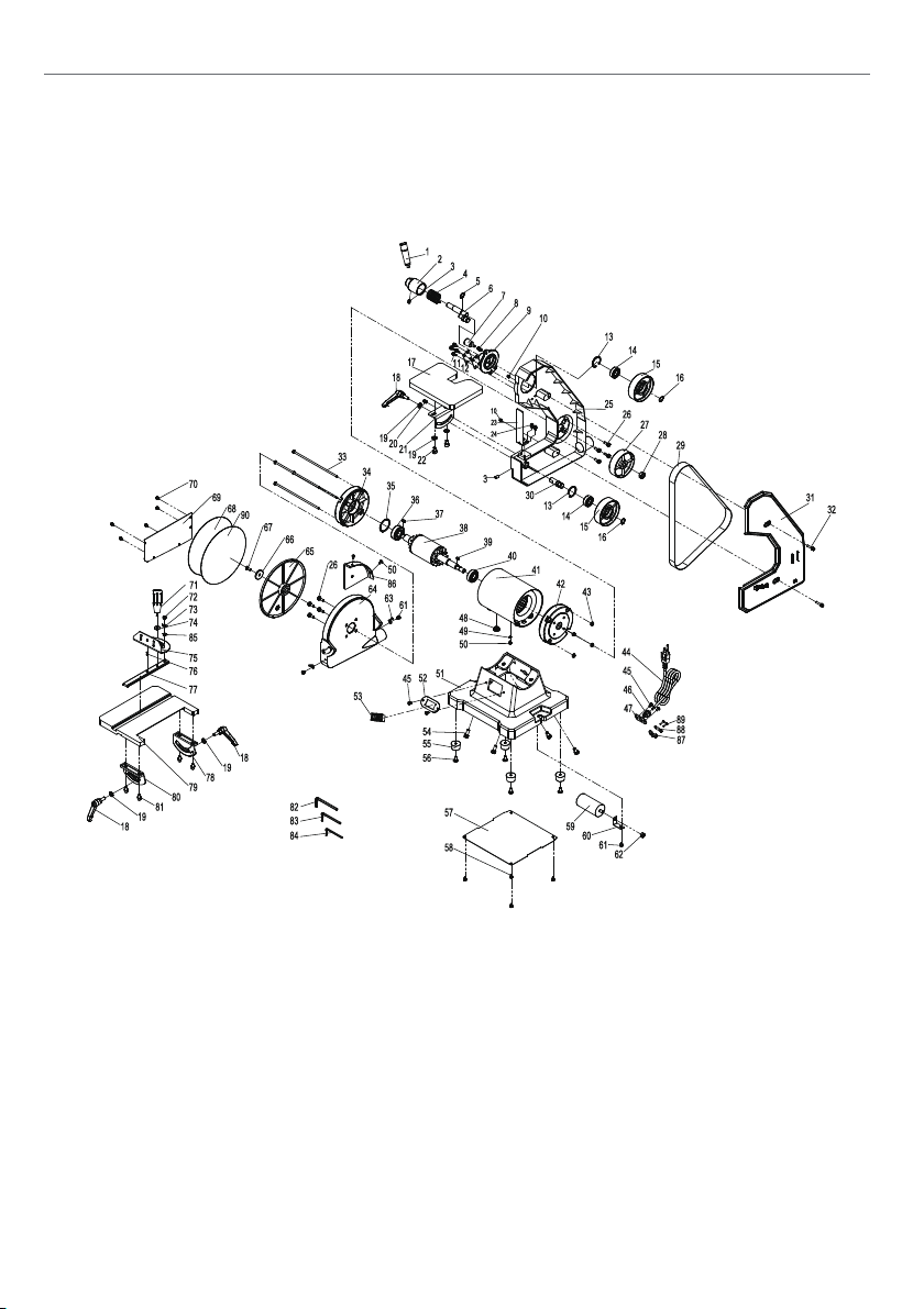
EXPLODED VIEW
18
18
Page 19
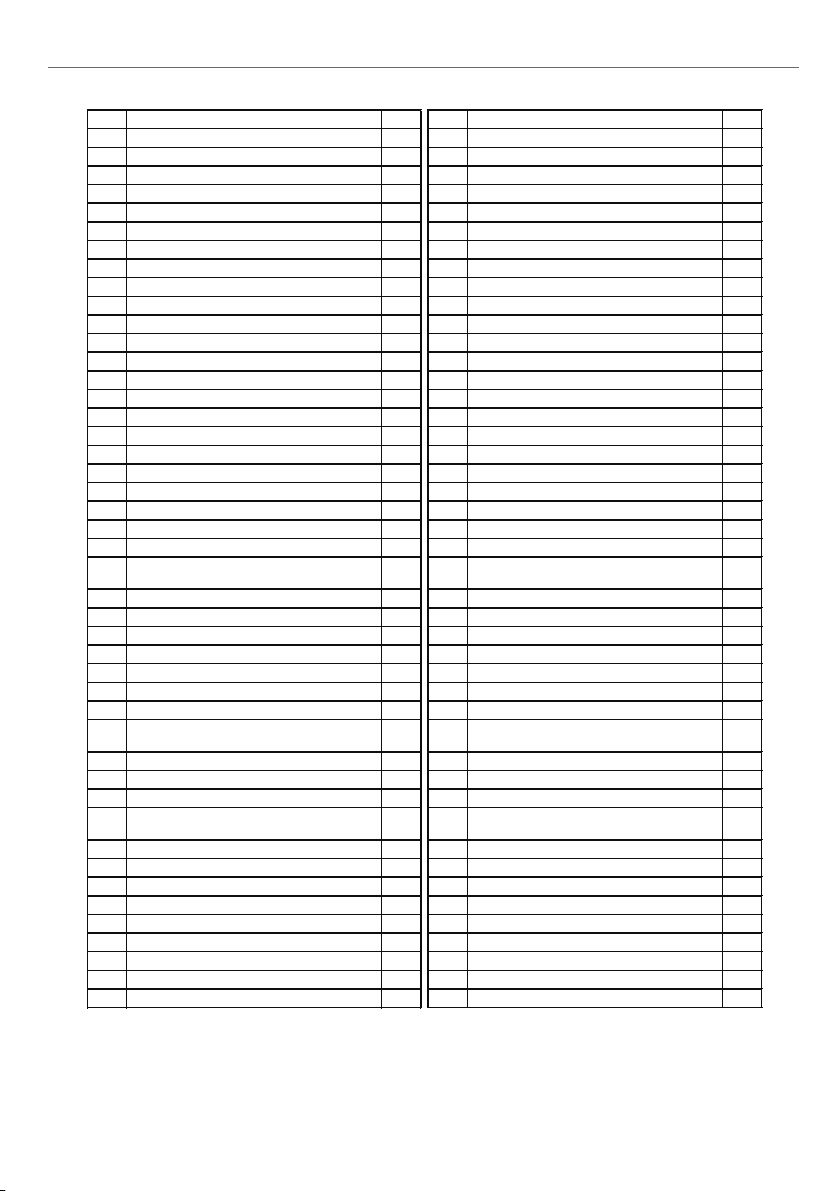
Part List
19
PART LIST
1 Belt tension knob 1 46 Cord clip-6P4 1
3 Hex screw M8×12 2 48 Cord bushing 1
4 Belt tension spring 1 49 External teeth lock washer D4 1
5 Circlip for shaft D16 1 50 Phillips screw with flat and spring washer M5×8 3
6 Driven eccentric shaft assembly 1 51 Base 1
7 Small knob 1 52 Switch plate 1
8 Housing handle spring 1 53 NVR switch 1
9 Belt driven support seat 1 54 Phillips bolt with spring washer M8x20 4
11 Phillips screw with flat and spring washer M5X12 4 56 Phillips screw with flat washer M5×16 4
14 Bearing 6202-2RZ 2 59 C apacitor 1
16 Circlip for shaft D15 2 61 Phillips screw with spring washer M5x8 3
17 Belt work table 1 62 Type I nut M8 1
18 Loki ng knob assembly 3 63 Pointer 2
19 F lat washer D8 5 64 Disc guard 1
20 Positioning bolt 1 65 Disc plate 1
21 B elt table support 1 66 Disc pad 1
22 Hexagon socket cap screw M8×12 2 67 Phillips screw M6×16-LH 1
washer M5×10
25 Belt guard base plate 1 70 Phillips screw with flat washer M4x8 5
26 Phillips screw with spring washer M6X18 8 71 Miter gauge knob 1
27 Driving wheel 1 72 Phillips screw with flat and srping washer M5x12 1
28 Hex nut M12 right 1 73 Pointer 1
29 Belt 1 74 Big flat washer D6 1
31 Belt guard cover 1 76 Pin 1
33 Phillips screw with flat washer M5X196 4 78 Disc work table left support 1
34 Left end cap 1 79 Disc wor table 1
35 Wave spring 1 80 Disc work table right support 1
37 Key 5×5×12 1 82 Allen wrench 6 1
38 Rotor 1 83 Allen wrench 5 1
39 Key 5×5×10 1 84 Allen wrench 4 1
40 Bearing 6203-2RZ 1 85 Type I hex nut M6 1
41 Rotor 1 86 Disc safety guard 1
42 Right end cap 1 87 Pressure plate 1
43 Hex. Flange nut M5 4 88 Pressure subplate 1
45 Phillips screw M5×8 4 9 0 Velcro 1
NO. Descripiton Qty. NO. Descripiton Qty.
2 Tension knob base 1 47 Cord clip plate 1
10 Type I non-metal lock nut M5 2 55 Rubber feet 4
12 Sanding belt adjustment plate 2 57 Base baseboard 1
13 Circlip for shaft D35 2 58 Phillips screw with flat washer M5×8 4
15 D riven pulley 2 60 Capacitor support 1
23 Be lt limiting plate 1 68 Sanding paper 1
Hexagon socket cap screw with flat and spring
24
2 69 Di sc guard board 1
30 Driven shaft 1 75 Miter gauge 1
Hexagon socket cap screw with flat and spring
32
36 Bearing 6204-2RZ 1 81
44 Power cord with plug 1 89 Phillips screw M4X16 2
washer M5×25
2 77 Miter bar 1
Hexagon socket cap screw with spring washer M6
×12
19
4
Page 20

Conformity Certicates
Axminster Tool Centre Ltd
UK DECLARATION OF CONFORMITY
‘original’
Product model: Axminster Workshop AW18BDS Belt and Disc Sander
Name and address of the manufacturer: Axminster Tool Centre Ltd, Unit 10 Weycroft Avenue,
Axminster, Devon EX13 5PH, United Kingdom
This declaration of conformity is issued under the sole responsibility of the manufacturer.
Object of the declaration:
The object of the declaration described above is in conformity with the relevant EU legislation:
Machinery Directive 2006/42/EC
EMC Directive 2014/35/EU
References to the relevant harmonised standards used or references to the other technical
specifications in relation to which conformity is declared:
EN ISO 12100:2010, EN 62841-1:2015
Additional information:
Name and address of person authorised to compile the technical file: Axminster Tool Centre
Ltd, Unit 10 Weycroft Avenue, Axminster, Devon E X13 5PH, United Kingdom
The machinery fulfils all relevant provisions of Supply of Machinery (Safety) Regulations 2008
as amended.
Signed for and behalf of: Axminster Tool Centre Ltd;
(place and date of issue): Axminster, Devon, United Kingdom, 13/1/25
(name, function): Andrew Parkhouse, Supply Chain Director
Signature:
Axminster Tool Centre Ltd
Product model: Axminster Workshop AW18BDS Belt and Disc Sander
Name and address of the manufacturer: Axminster Tool Centre Ltd, A-201, Haagsche Hof,
Parkstraat 83, The Hague, 2514 JG, Netherlands
This declaration of conformity is issued under the sole responsibility of the manufacturer.
Object of the declaration:
The object of the declaration described above is in conformity with the relevant EU legislation:
Machinery Directive 2006/42/EC
EMC Directive 2014/35/EU
References to the relevant harmonised standards used or references to the other technical
specifications in relation to which conformity is declared:
EN ISO 12100:2010, EN 62841-1:2015
Additional information:
Name and address of person authorised to compile the technical file: Axminster Tool Centre
Ltd, A-201, Haagsche Hof, Parkstraat 83, The Hague, 2514 JG, Netherlands
The machinery fulfils all relevant provisions of Supply of Machinery (Safety) Regulations 2008
as amended.
Signed for and behalf of: Axminster Tool Centre Ltd;
(place and date of issue): Axminster, Devon, United Kingdom, 13/1/25
(name, function): Andrew Parkhouse, Supply Chain Director
EC DECLARATION OF CONFORMITY
‘original’
Signature:
20
Page 21

Conformity Certicates
Axminster Tool Centre Ltd
UK DECLARATION OF CONFORMITY
Product model: Axminster Workshop AW18BDS Belt and Disc Sander
Name and address of the manufacturer: Axminster Tool Centre Ltd, Unit 10 Weycroft Avenue,
Axminster, Devon EX13 5PH, United Kingdom
This declaration of conformity is issued under the sole responsibility of the manufacturer.
Object of the declaration:
The object of the declaration described above is in conformity with the relevant EU legislation:
Machinery Directive 2006/42/EC
EMC Directive 2014/35/EU
References to the relevant harmonised standards used or references to the other technical
specifications in relation to which conformity is declared:
EN ISO 12100:2010, EN 62841-1:2015
Additional information:
Name and address of person authorised to compile the technical file: Axminster Tool Centre
Ltd, Unit 10 Weycroft Avenue, Axminster, Devon E X13 5PH, United Kingdom
The machinery fulfils all relevant provisions of Supply of Machinery (Safety) Regulations 2008
as amended.
Signed for and behalf of: Axminster Tool Centre Ltd;
(place and date of issue): Axminster, Devon, United Kingdom, 13/1/25
(name, function): Andrew Parkhouse, Supply Chain Director
‘original’
Signature:
21
Page 22

22
Page 23

23
Page 24

The packaging is suitable for recycling.
Please dispose of it in a responsible manner.
EU Countries Only
Do not dispose of electric tools together with household waste material.
By law they must be collected and recycled separately.
Axminster Tools, Axminster Devon EX13 5PH
axminstertools.com
 Loading...