

Page 1
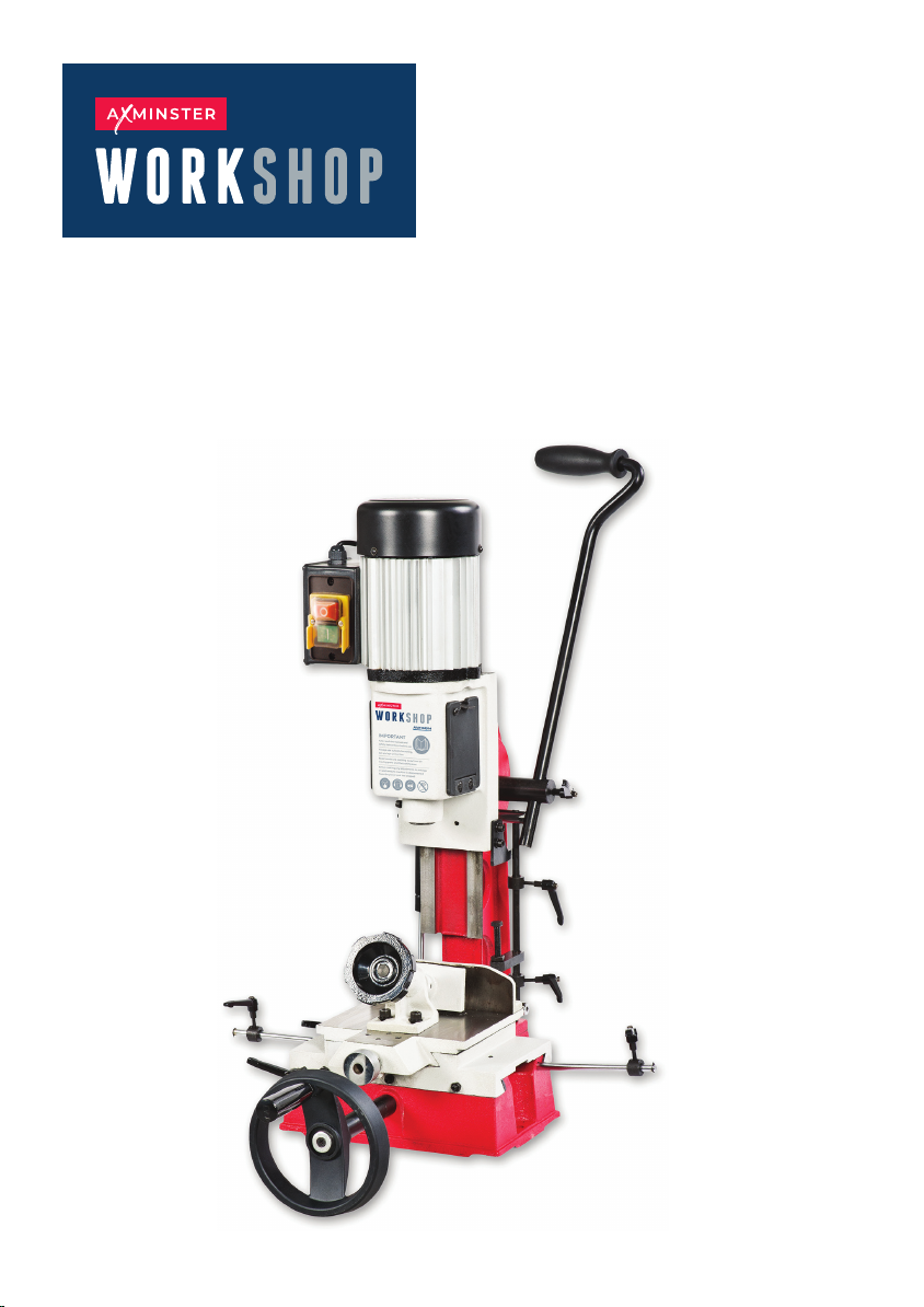
AW16BM
Bench Morticer
Code 107675
Original Instructions
AT: 1/9/2025
BOOK VERSION: 7
Page 2
INDEX OF CONTENTS
EU Declaration of Conformity 02
What’s Included 03
General Instructions for 230V Machines 04
Specic Safety Instructions for Morticers 04
Assembly 05
Specication 07
Illustration and Parts Description 07
Setting up the Machine 10
Optional Accessories 14
Maintenance 15
Exploded Diagrams/Lists 16
Wiring Diagram 18
Notes 19
EU DECLARATION OF CONFORMITY
The symbols below advise the correct safety procedures when using this machine.
Fully read manual
and safety instructions
before use
Ear protection
should be worn
Eye protection
should be worn
Dust mask
should be worn
2
HAZARD
Motor gets hot
Page 3
WHAT’S INCLUDED
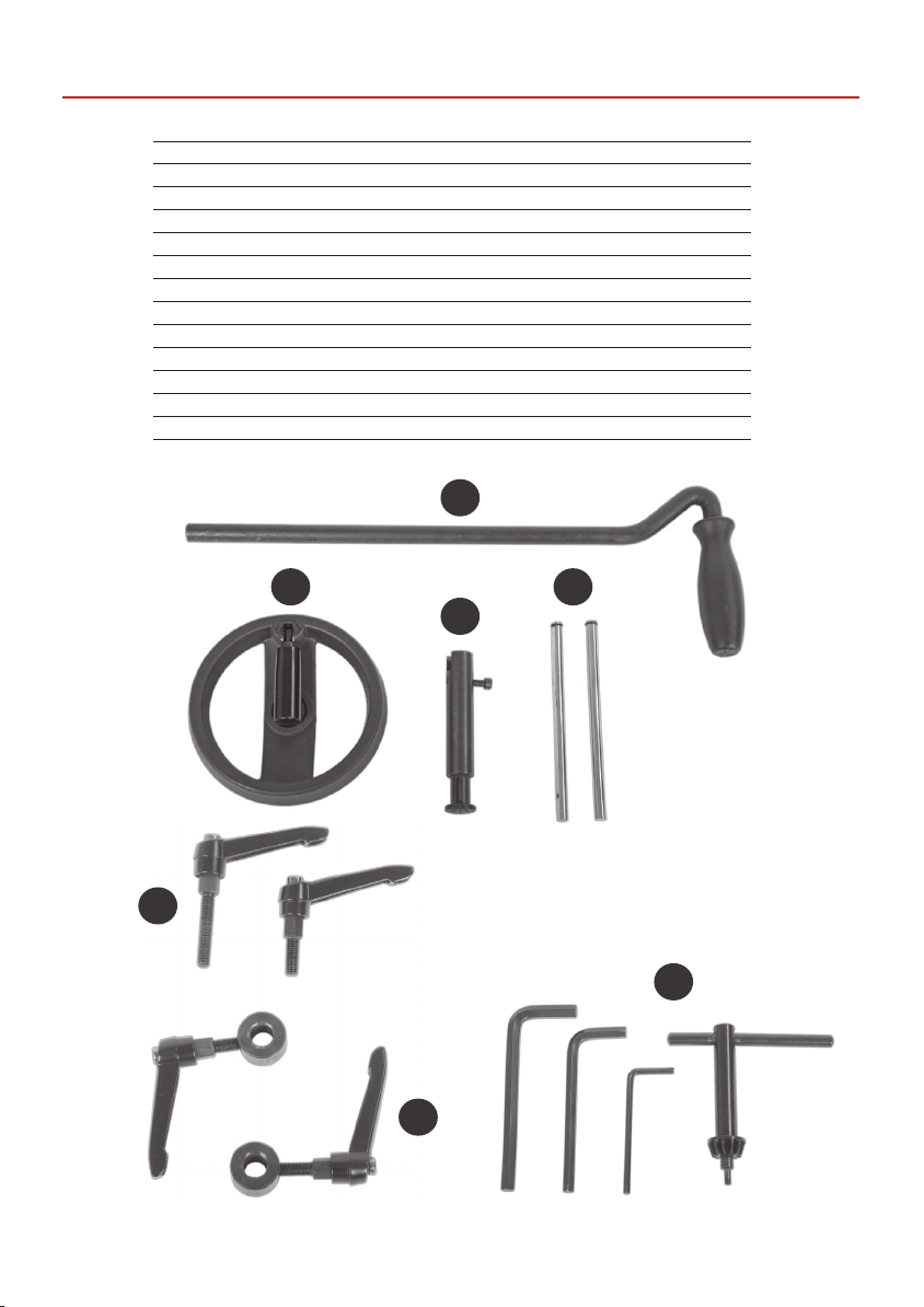
Quantity Item Part
1 AW16BM Bench Morticer
1 Operating Lever A
1 Saddle Operating Wheel B
1 Operating Wheel Shaft C
2 Distance Stop Rods D
Bag 1
2 M6 x 30mm and M6 x 16mm Lift and Shift Handles E
2 Ring Collar Clamps with Lift and Shift Handles F
Bag 2
1 13mm Chuck Key, 6,5,3mm Allen Keys G
1 Instruction Manual
A
B
D
C
E
G
F
3
Page 4
GENERAL INSTRUCTIONS FOR 230V MACHINES
The following will enable you to observe good working
practices, keep yourself and fellow workers safe and maintain your tools and equipment in good working order.
WARNING!! KEEP TOOLS AND
EQUIPMENT OUT OF REACH OF
YOUNG CHILDREN
KEEP WORK AREA AS
UNCLUTTERED AS IS PRACTICAL.
UNDER NO CIRCUMSTANCES
SHOULD CHILDREN BE ALLOWED
IN WORK AREAS.
Mains Powered Tools
• Tools are supplied with an attached 13 Amp plug.
• Inspect the cable and plug to ensure that neither are
damaged. Repair if necessary by a suitably qualied
person.
• Do not use when or where it is liable to get wet.
Workplace
• Do not use 230V a.c. powered tools anywhere
within a site area that is ooded.
• Keep machine clean.
• Leave machine unplugged until work is about to
commence.
• Always disconnect by pulling on the plug body
and not the cable.
• Carry out a nal check e.g. check the cutting tool
is securely tightened in the machine and the
correct speed and function set.
• Ensure you are comfortable before you start work,
balanced, not reaching etc.
• Wear appropriate safety clothing, goggles, gloves,
masks etc. Wear ear defenders at all times.
• If you have long hair wear a hair net or helmet to prevent
it being caught up in the rotating parts of the machine.
• Consideration should be given to the removal of rings
and wristwatches.
• Consideration should also be given to non-slip
footwear etc.
• If another person is to use the machine, ensure they are
suitably qualied to use it.
• Do not use the machine if you are tired or distracted.
• Do not use this machine within the designated safety
areas of ammable liquid stores or in areas where there
may be volatile gases.
• Check cutters are correct type and size, are
undamaged and are kept clean and sharp, this will
maintain their operating performance and lessen the
loading on the machine.
• OBSERVE…. make sure you know what is
happening around you and USE YOUR COMMON SENSE.
SPECIFIC SAFETY INSTRUCTIONS FOR MORTICERS
1. Ensure that the morticer is rmly xed to its base as the
force exerted through the operating handle could be
enough to over-balance the machine.
2. Ensure that the operating handle is returned to the
upright position after cutting a mortise.
3. Mortice chisels have very sharp ends, handle them with
great care.
4. Make sure that the timber is held rmly down against
the table by using the table clamp. This prevents the
possibility of the timber being pulled upwards as the
mortice chisel is withdrawn from the hole.
4
Page 5
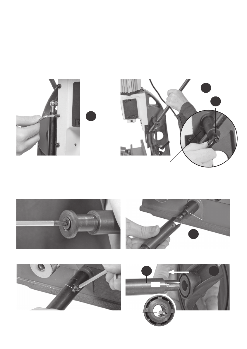
ASSEMBLY
Please take some time to read the section entitled
“Illustration and Parts Description” to identify the
various parts of your machine so that you are familiar
with the terminology we will use to enable you to set
up and operate your Morticer safely and correctly.
Place the machine onto a suitable surface, at a height that
will enable you to work comfortably and to ensure that
Fig 1.
Fig 2.
there is adequate room on either side for the size of timber
you plan to use. Once you are happy, bolt the morticer
down. Loosen the locking caphead screw (a) to raise the
morticer’s head assembly. Locate the operating lever (A)
and the M6 x 16mm lift and shift handle (E), introduce the
operating lever through the rack and pinion assembly,
then secure the lever in place using the M6 lift and shift
handle (E) (See g 2).
A
E
a
Rack and pinion assembly
Locate the operating wheel Shaft (C), remove the phillips screw, clamping washer and M6 x 23mm caphead screw and
place them safely aside (See gs 3 and 5). Slide the machined cutout onto the transverse table shaft mechanism, line up
the pre-drilled hole with the one in the table shaft mechanism and secure them in position using a 5mm allen key and
the M6 x 23mm caphead screw you removed earlier (See gs 4 and 5).
Fig 3.
Remove the phillips screw and clamping washer.
Fig 5.
M6 Caphead
screw
Secure the wheel shaft (C) to the table
shaft using the M6 caphead screw.
Fig 4.
Slide the machined cutout onto the
transverse table shaft mechanism.
Fig 6.
Locating
key
C B
Slot
Slide the operating wheel (B)
onto the operating shaft (C).
5
Table shaft
mechanism
C
Page 6
ASSEMBLY
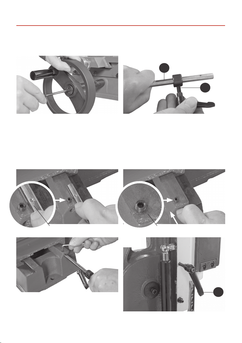
Locate the operating wheel (B), slide it on to the operating wheel shaft (C) as shown in g 6 (Note: Make sure the
locating key engages into the shaft’s machined slot). Secure using the phillips screw and clamping washer you
removed earlier (See g 7).
Fig 7.
Fig 8.
C
F
Secure the operating wheel (B) using the phillips screw
and clamping screw.
Move the table to the left by turning the operating wheel (B), thus revealing the grub screw beneath. Locate one of the
two distance stop rods (D) and a ring collar clamp (F), slide the ring collar clamp (F) onto the distance stop rod (D) and
lightly tighten by turning the lift and shift handle, see g 8 on the previous page. Line up the countersink mark on the
rod (D) with the grub screw, (make sure the grub screw is raised fully) slide the rod (D) into the pre-drilled hole to the
end of casting and tighten the grub screw (See gs 9,10 and 11) repeat for the opposite side.
Fig 9.
Slide the ring collar clamp (F) onto the distance stop rod
(D) and lightly tighten.
Fig 10.
Countersink mark Grub screw
Fig 11.
Remove locking caphead screw (a) (see page 5), that locks
the morticers head assembly and replace it with the M6 x
30mm lift and shift handle (E) (See g 12).
6
Fig 12.
E
Page 7
SPECIFICATION
Code 107675
Model AW16BM
Rating Workshop
Power 550 W
Voltage 230 V
Chisel Stroke 100 mm
Centre of Chisel to Back Fence 55 mm
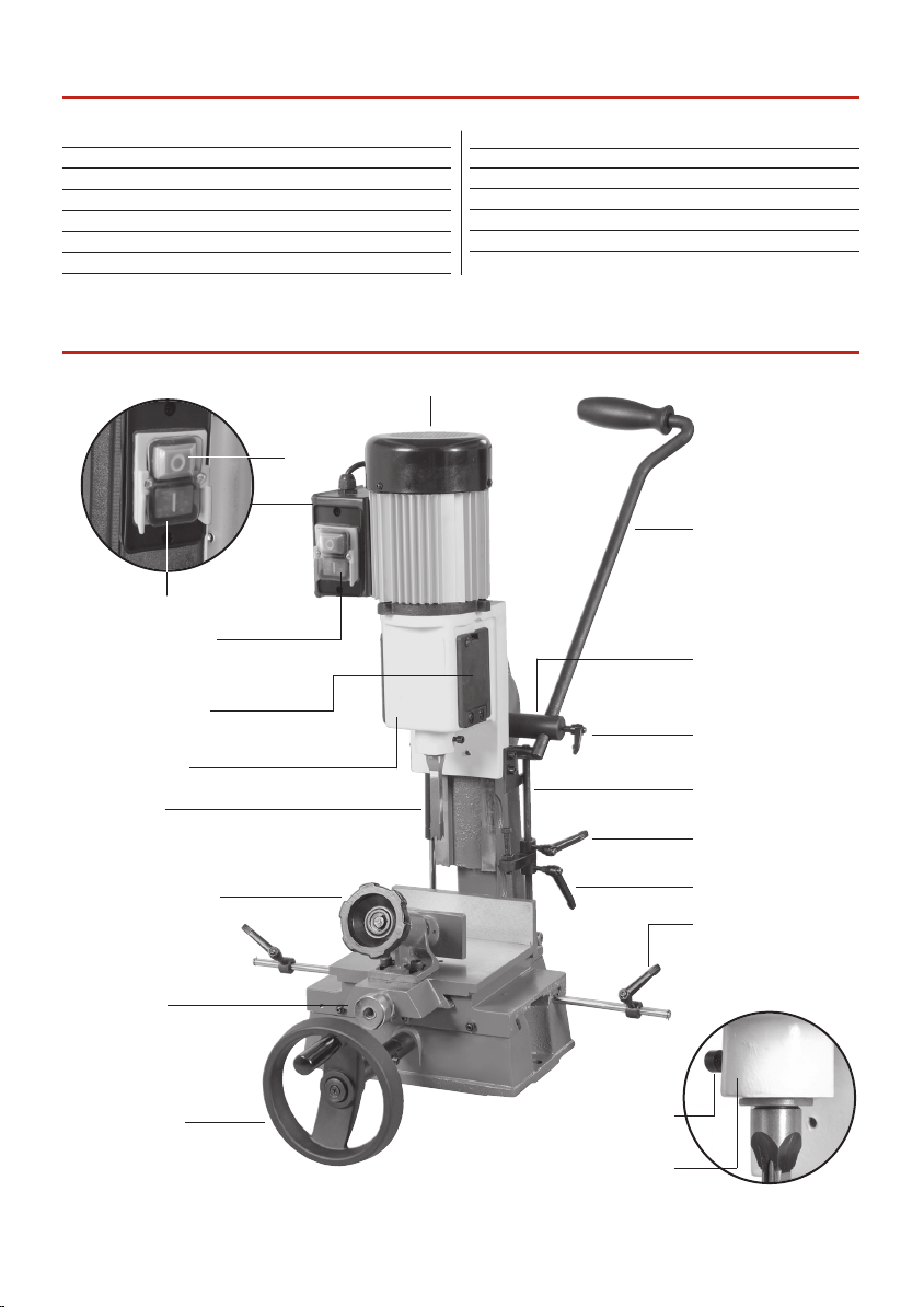
ILLUSTRATION AND PARTS DESCRIPTION
Motor
On
O
NVR switch assembly
Chuck access doors
Headbox casting
Hollow chisel
Max Height of Timber with 12.7mm Chisel and Bit
110 mm (160 mm with optional spacer block)
Max Chisel Size Softwood 16 mm
Max Chisel Size Hardwood 16 mm
Overall L x W x H 520 mm x 580 mm x 640 mm
Weight 42 kg
Operating lever
Rack and pinion rise
and fall mechanism
M6 x 16mm lift
and shift handle
Depth stop assembly
Head rise stop
Table clamp assembly
Worktable gib
strip adjuster
Crossfeed table
control knob
Transverse table
control wheel
Mortice depth stop
Distance stop
assembly
Chisel clamping bolt
Chisel mounting ange
7
Page 8
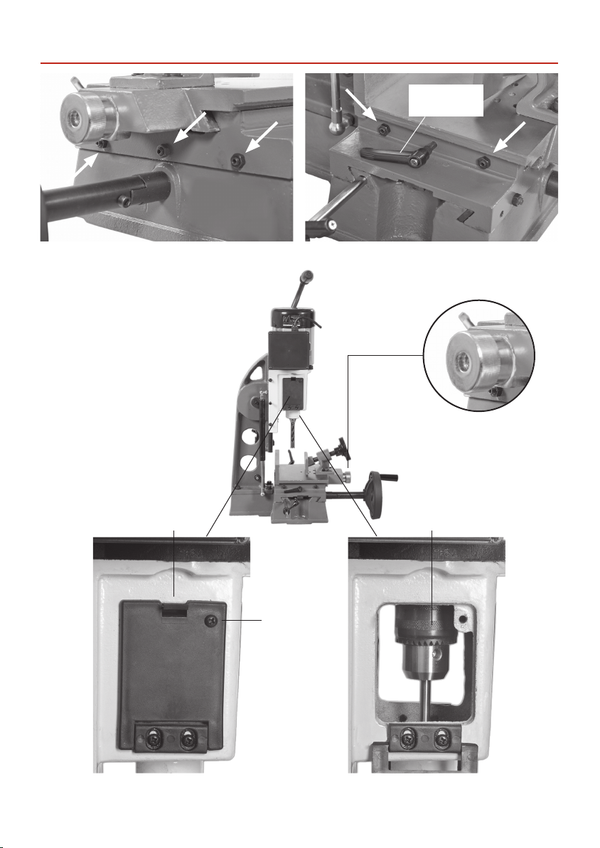
ILLUSTRATION AND PARTS DESCRIPTION
Transverse gib strip adjusters Table gib strip adjusters
Lift and shift
handle lock
Table ne feed control knob
Chuck door
securing screw
8
Auger mounting chuckDoor catch
Page 9
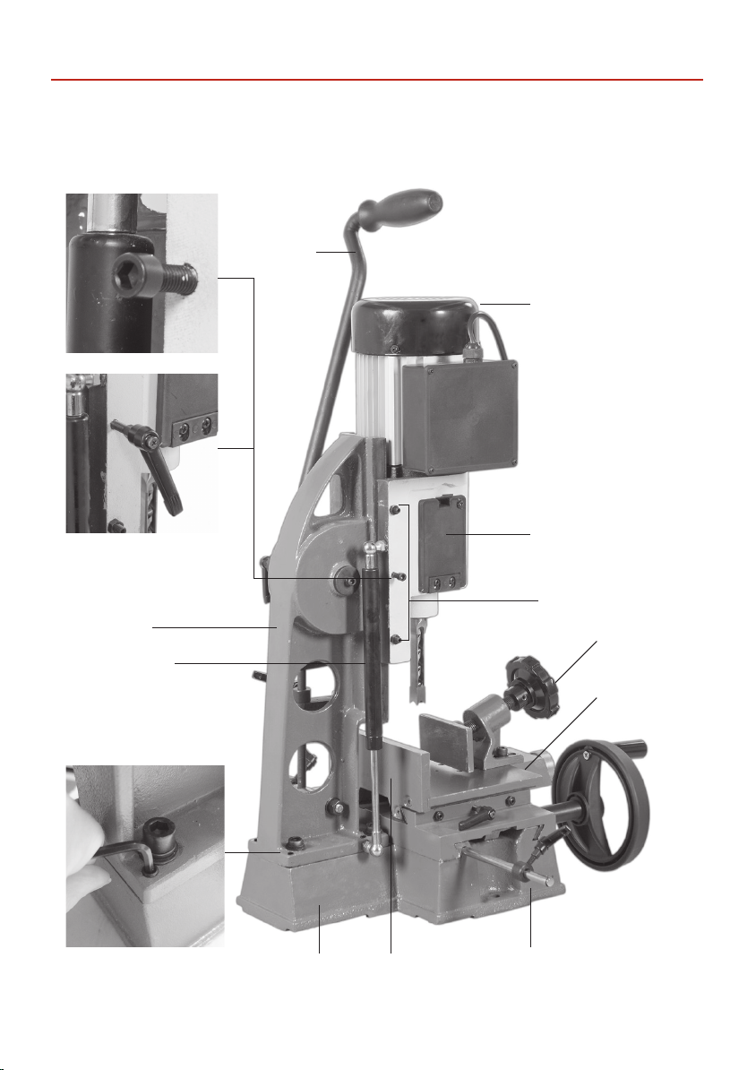
Locking bolt
Lift and shift handle lock
ILLUSTRATION AND PARTS DESCRIPTION
Operating lever
Motor
Chuck access door
Headbox support
column
Gas powered
head return
strut
Adjustment grub screw, one
to each corner for squaring
up the support column
Base casting
Headbox gib
strip adjusters
Table clamping
assembly
Table
Fence Distance stop assembly
9
Page 10
SETTING UP THE MACHINE
Initial Set up
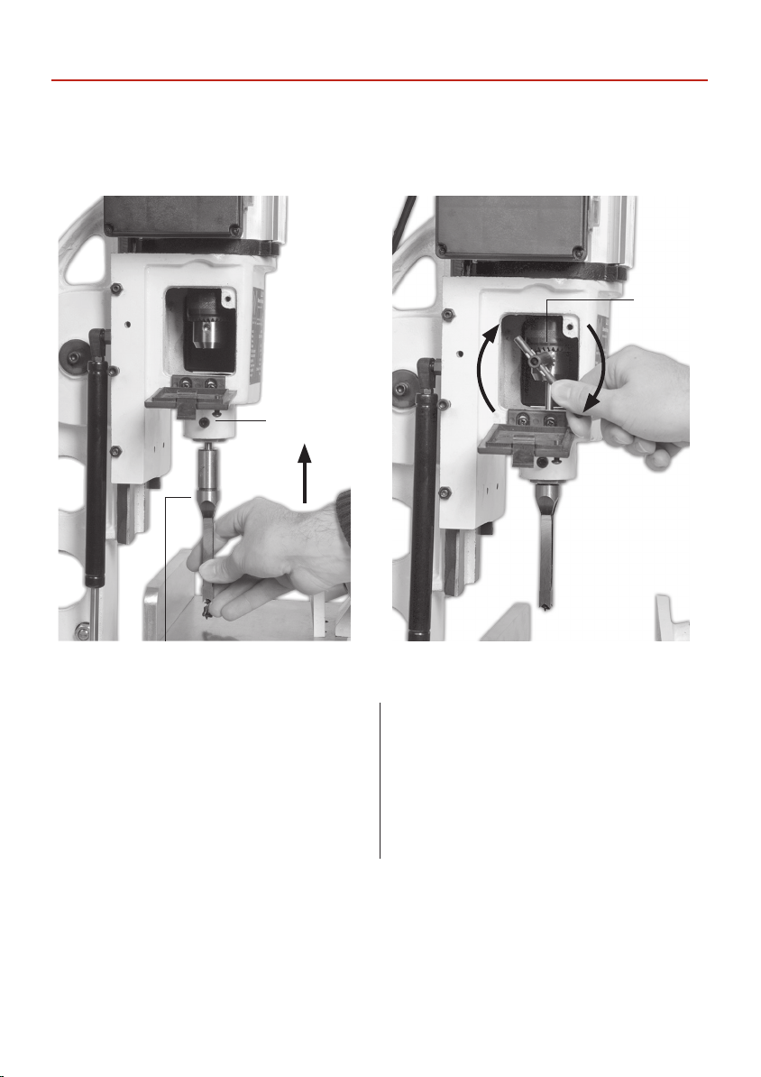
Introduce the chisel into the adaptor collar, press the auger up into the chuck, tighten the chuck and withdraw the chuck
key. Gently pinch the chisel in place by nger tightening the clamping bolt. (See gs A,B)
Fig A. Fig B.
Chuck key
Clamping bolt
Hollow Chisel
Setting the Chisel Auger Clearance
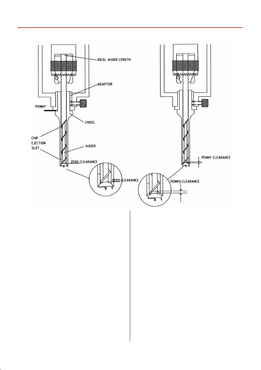
The old rule of thumb for chisel auger clearance was
known as “the one penny width”. This was achieved by
introducing a penny between the locating shoulder of the
chisel and the adaptor face, with the auger locked in place
and with the chisel pulled hard down on the auger. The
penny was then removed and the chisel pushed up to the
adaptor face and locked in place, this established the “one
penny width” between the chisel and the auger, which for
general timbers and mortice sizes is quite adequate.
Traditional morticers normally had a cross pin in the auger
mounting mandrel, to prevent the auger being pushed
back up into the chisel. The mounting method on the
newer morticers is a chuck. It is well worth taking the extra
time and care to prepare your augers to give the correct
‘reach’ when ‘bottomed’ out in the chuck. This will prevent
the auger being pushed back towards the chisel and
altering the clearance setting. (See g C)
10
Page 11
SETTING UP THE MACHINE
Setting the chisel auger clearance
Fig C.
General Notes
The mortise will generate a lot of ‘grip’ on the chisel,
especially the rst cut, or if the timber is a little green.
Make sure you use the table clamp assembly to help
control the timber during the raise operation of the
morticer.
Setting the chisel Square
When the chisel is tightened in the machine it must
normally be square to the back fence. The easiest way to
achieve this is to bring the headbox down to bring the
chisel as close to the table as possible, set a square against
the back fence and set the side of the chisel against the
square and clamp tight. (Remember to have the chip
ejection slot in the chisel to the side from which you will
cut the mortice).
Quick Setting of the Mortice Depth
Put a mark on an easily accessible end of the workpiece to
be mortised, at the depth you require. Pull the headbox
down, and put the end of the timber against the chisel.
Position the headbox so that the chisel points or the
auger point are at the depth required, raise the depth stop
collar to the underside of the headbox and tighten gently.
Recheck the depth of the chisel point, if it is satisfactory
tighten securely, if not it can be gently ‘nudged’ down the
column with the headbox, then tighten. Reposition the
operating handle to give the most comfortable position
and purchase on the lever, over the full distance of the
movement you have just set.
Headbox Rise Adjustment
Coupled with the depth stop on the same assembly is the
head box rise limiter. This limits the rise of the headbox /
chisel to a convenient distance above the work by the use
of a locking collar positioned above the stop nger on the
side of the headbox. The travel of this assembly is then
restricted to your chosen setting rather than having to
return it to the top of the slide each time.
11
Page 12
SETTING UP THE MACHINE
Depth Stop Assembly
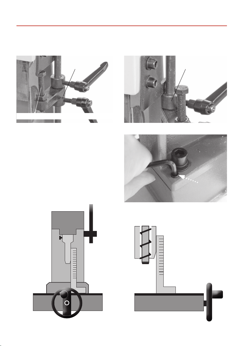
The hinged depth stop can be using to adjust the depth of the morticer (See g A). The ring collar clamp can also be
used as a depth stop (See g B).
Fig A. Fig B.
Hinged depth stop
To make ne adjustment, adjust the height of the bolt
Support Column Leveling Grub Screws
Place an engineer square against the side of the mortice
chisel, check it’s square. If adjust is required adjust the
grub screws to each corner of the support columns
base until the chisel is perpendicular to the worktable.
Re-postion the square to the front face of the chisel and
repeat the procedure. Nip-up the four M10 bolts to the
columns base to secure.
Ring collar clamp
Mortice
chisel
12
Engineer’s
square
Page 13
SETTING UP THE MACHINE
Table Clamp Assembly
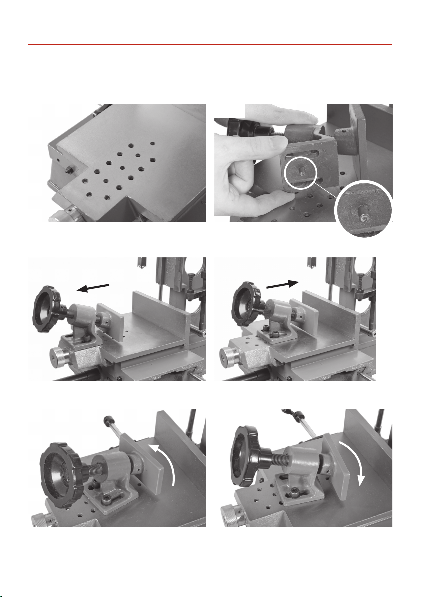
The table clamp can be adjusted to accommodate dierent sizes of timber using the pre-drilled holes in the table
(See gs 13,15 and 16). To the base of the clamp there is pin which slots into the centre holes in the table to prevent
movement (See gs 13 and 14). The clamp can also be pivoted to clamp uneven shapes (See gs 17 and 18).
Fig 13.
The table has pre-drilled holes which allows the clamp to
be repositioned.
Fig 15.
The table clamp can be adjusted to accommodate dierent sizes of timber.
Fig 14.
To the base of the clamp is a pin
that slots into the centre holes in the table.
Fig 16
Fig 17.
Fig 18.
The clamp can be pivoted to clamp uneven shapes.
13
Page 14
OPTIONAL ACCESSORIES
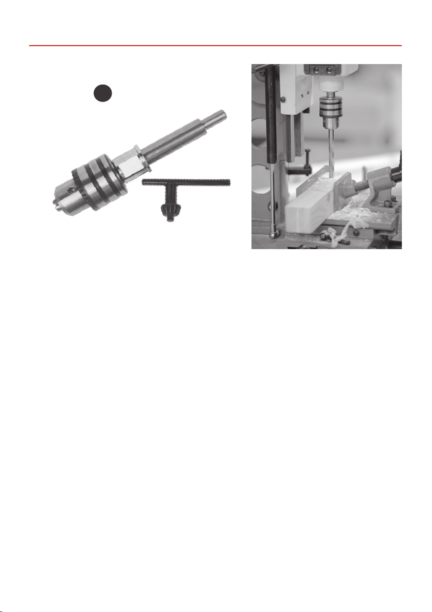
Drill Chuck and Adaptor (Order no: 400287)
I
You can turn your morticer into a pillar drill by attaching a drill chuck and adaptor.
14
Page 15
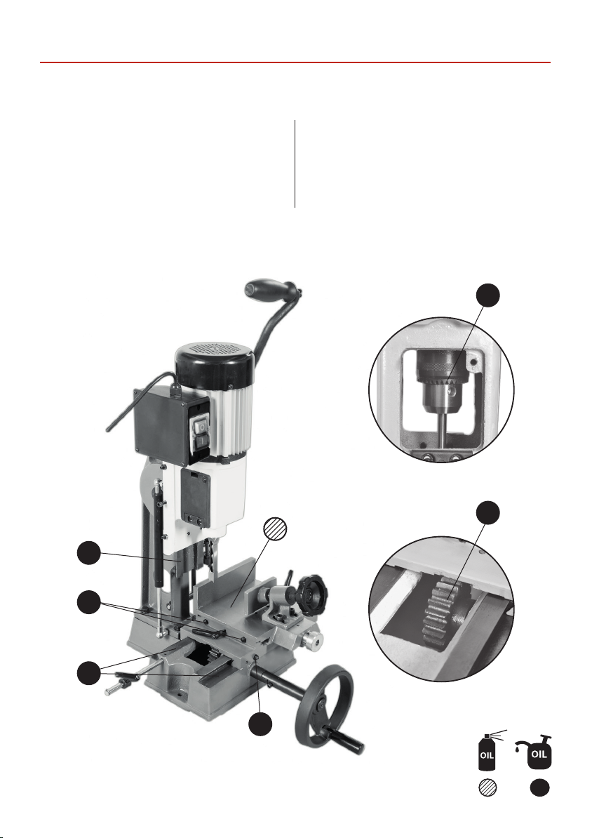
There is very little maintenance required on your morticer.
MAINTENANCE
Keep it clean
Make sure the rack and pinion gears do not become
clogged with chips/sawdust.
Lightly spray oil on all exposed metal surfaces if the
machine is going to stand idle for any length of time. Keep
the chisels and augers sharp.
There are full ranges of mortice chisels and sharpening sets listed on our website.
Once a month
Blow/suck the motor to remove any debris that might
have lodged in the fan cover.
Oil the chuck and exercise it over its full range to ensure
the oil coats all moving parts.
15
Page 16
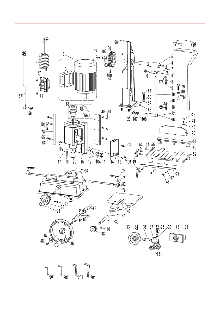
EXPLODED DIAGRAMS/LISTS
16
Page 17

EXPLODED DIAGRAMS/LISTS
NO. SIZE DESCRIPTION QTY
1 Operating handle 1
2 Motor 1
3 Switch box 1
4 Handle 1
5 Operating shaft 1
6 M10 Hex nut 1
7 Shaft 1
8 Handle 1
9 Setting Collar 1
10 Guide column 1
11 M6x12 Screw 2
12 Localiser 1
13 M5x16 Screw 2
14 Cover 2
15 Headbox Casting 1
16 Handle 1
17 6 Spring washer 4
18 Setting Collar 1
19 M6x25 Screw 4
20 Chisel Bushing 1
22 Shaft 1
23 M10 Hex nut 1
24 Drift 1
25 Base 1
26 M6x25 Screw 1
28 gear 1
31 M6x10 Screw 1
32 M8x20 Hexagon head
bolt
33 Handwheel 1
34 M6x10 Screw 1
35 Lead screw 1
36 8 Flat washer 2
2
37 Connecting bend 1
38 Table control knob 1
39 Lead screw 1
40 M6x10 Screw 1
41 Nut block 1
42 Worktable 1
43 Clamp plate 1
44 6 Spring washer 2
45 M6x20 Screw 2
46 6 Flat washer 2
47 M6x30 Screw 3
48 M6 Hex nut 3
49 Handle 1
50 M6x12 Screw 4
51 Horizontal rack 1
52 Sliding table 1
53 M6 Hex nut 3
54 M6x30 Screw 3
55 Drift 1
57 Screw 1
58 M8 Horizontal rack 2
59 10 Sliding table 4
60 Hex nut 1
61 M10x30 Screw 4
62 M6x16 Drift 1
63 6 Washer 1
64 M6x25 Screw 2
65 M6 Hex nut 2
66 Drill chuck 1
66.1 Chuck key 1
67 Switch 1
68 Column 1
69 Rack 1
70 M6x12 Screw 6
17
Page 18
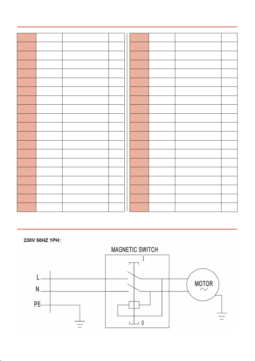
EXPLODED DIAGRAMS/LISTS
71 S T4x 12 Screw 2
72 Plug 1
74 Handle 2
75 Setting collar 2
76 Distance stop rod 2
77 Grip sleeve 1
78 Drift 1
79 Hex bolt 1
80 Nut 1
81 Locating block 1
82 9 C-ring 2
83 Gear shaft 1
84 Connecting shaft 1
85 Handle 1
86 Screw 2
87 Washer 1
88 Screw 1
90 Fence 1
93 16 C-ring 1
94 M6x6 Screw 2
95 8 Spring washer 2
96 M6x8 Screw 1
97 M6x8 Screw 1
98 M8x12 Grub screw 4
99 10 Spring washer 4
100 M8x45 Screw 1
101 Handle 1
102 M6x20 Screw 1
103 6 Spring washer 1
104 6 Spring washer 2
105 Hinge plate 2
106 M5x10 Screw 4
107 10 Spring washer 1
108 10 Flat washer 1
151 5X16 Key 1
152 6X14 Pin 1
201 S3 Allen wrench 1
202 S4 Allen wrench 1
203 S5 Allen wrench 1
204 S6 Allen wrench 1
EXPLODED DIAGRAMS/LISTS
18
Page 19

NOTES
19
Page 20

The packaging is suitable for recycling.
Please dispose of it in a responsible manner.
EU Countries Only
Do not dispose of electric tools together with household waste material.
By law they must be collected and recycled separately.
Axminster Tools, Axminster Devon EX13 5PH
axminstertools.com
 Loading...