

Page 1

Code 107824
Original Instructions
AW1502WSG
Wide Stone Bench Grinder
AT: 29/05/2025
BOOK VERSION: 3
Page 2
INDEX OF CONTENTS
EU Declaration of Conformity 02
What’s Included 03
General Instructions for 230V Machines 04
Specific Safety Precautions for Grinding Machines 04-05
Assembly 05-06
Illustration and Parts Description 07
Specification 08
Setting Up the Grinder 08-09
Changing the Grinding Stone 09-10
Dressing the Stone 11
Exploded Diagrams/Lists 12-13
Wiring Diagram 14
Notes 15
EU DECLARATION OF CONFORMITY
Cert No: HBG620HA
Axminster Tool Centre Ltd
Axminster Devon
EX13 5PH UK
axminstertools.com
declares that the machinery described:-
Type Bench Grinder
Model AW1502WSG
Signed
Andrew Parkhouse
Operations Director
Date: 19/03/2020
EU Declaration of Conformity
This machine complies with the following directives:
2006/42EC
2014/30/EU
EN 62841-1: 2015
EN 62841-3-4: 2016+A11: 2017
and conforms to the machinery example for which the
EC Type-Examination Certificate No SHES190802201801TLC, SHEM200100029301PTC
has been issued by Wendeng Allwin Motors Manufacturing Co., Ltd.
at: No. 15 Sichan Road Wendeng, Shandong 264400 P.R.China
and complies with the relevant essential health and safety requirements.
EN 55014-1: 2017
EN 61000-3-2: 2014
EN 61000-3-3: 2013
EN 55014-2: 2015
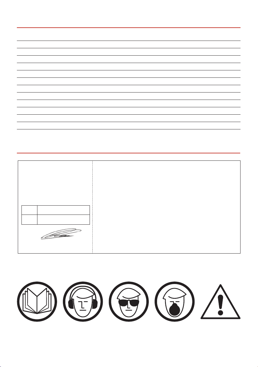
The symbols below advise the correct safety procedures when using this machine.
Fully read manual
and safety instructions
before use
Ear protection
should be worn
Eye protection
should be worn
Dust mask
should be worn
HAZARD
Motor gets hot
2
Page 3
WHAT’S INCLUDED
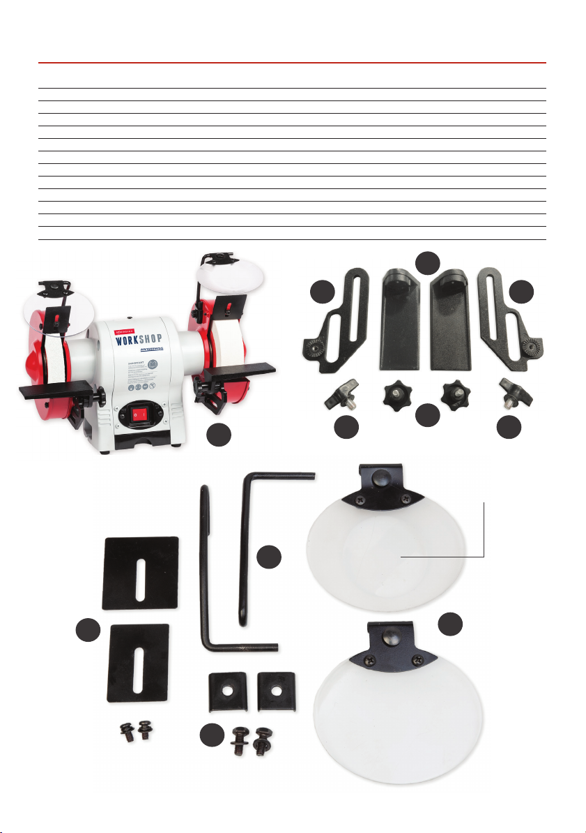
Quantity Item Part Model Number
AW1502WSG
1 Wide Stone Bench Grinder A
2 Left/Right Hand Tool Rest Mounting Brackets B
2 Left/Right Hand Adjustable Tool Rests C
2 Butterfly Knobs & Washers D
2 Tool Rest Clamping Knobs & Washers E
2 Spark Guard Brackets with Screws/Washers F
2 Eye Shield Mounting Bars G
2 Mounting Bar Square Brackets
with Bolts & Washers H
2 Eye Sheilds, with One Magnifying Glass I
1 Instruction Manual
C
BB
L R
E
A
Magnifying glass
DD
G
F
I
H
3
Page 4

GENERAL INSTRUCTIONS FOR 230V MACHINES
The following will enable you to observe good working
practices, keep yourself and fellow workers safe and
maintain your tools and equipment in good working
order.
WARNING!! KEEP TOOLS AND
EQUIPMENT OUT OF REACH
OF YOUNG CHILDREN
KEEP WORK AREA AS
UNCLUTTERED AS IS PRACTICAL
UNDER NO CIRCUMSTANCES
SHOULD CHILDREN BE ALLOWED
IN WORK AREAS.
Mains Powered Tools
• Tools are supplied with an attached 13 Amp UK 3 pin
plug, fitted with 5 amp fuse
• Inspect the cable and plug to ensure that neither are
damaged. Repair if necessary by a suitably
qualified person.
• Do not use when or where it is liable to get wet.
Workplace
• Do not use 230V a.c. powered tools anywhere
within a site area that is flooded.
• Keep machine clean.
• Leave machine unplugged until work is about to
commence.
• Always disconnect by pulling on the plug body
and not the cable.
• Carry out a final check e.g. check the cutting tool
is securely tightened in the machine and the
correct speed and function set.
• Ensure you are comfortable before you start work,
balanced, not reaching etc.
• Wear appropriate safety clothing, goggles, gloves,
masks etc. Wear ear defenders at all times.
• If you have long hair wear a hair net or helmet to
prevent it being caught up in the rotating parts of the
machine.
• Consideration should be given to the removal of rings
and wristwatches.
• Consideration should also be given to non-slip
footwear etc.
• If another person is to use the machine, ensure they
are suitably qualified to use it.
• Do not use the machine if you are tired or distracted.
• Do not use this machine within the designated safety
areas of flammable liquid stores or in areas where
there may be volatile gases.
• Check cutters are correct type and size, are
undamaged and are kept clean and sharp, this will
maintain their operating performance and lessen the
loading on the machine.
• OBSERVE…. make sure you know what is
happening around you and USE YOUR COMMON
SENSE.
SPECIFIC SAFETY PRECAUTIONS FOR GRINDING MACHINES
1. Do not operate your machine until it is completely
assembled and installed according to the instructions.
2. If you are not familiar with the operation of
grinding machines obtain advice from your supervisor
or instructor or another qualified person.
3. Only use grinding wheels or attachments rated
higher than 3600 rpm with a 5/8”(16mm) arbor on this
machine.
4. Never use a chipped or cracked wheel. Always
inspect each wheel before mounting it on the grinder.
If during inspection you discover a damaged grinding
wheel, replace it immediately.
5. Do not over tighten wheel nuts.
6. Always maintain a distance of 2mm or less between
the wheel and the tool rest. Adjust the tool rests as the
wheels decrease in size.
7. Ensure the tool rests are tightened so they cannot
move while in use.
8. Never grind on a cold wheel. The grinder should
always be run for at least one minute before applying
work to it.
9. Never grind on the side of the wheel. Always grind
on the face of the wheel only.
10. Never apply coolant directly to a grinding wheel,
it may cause the bonding to fail. If the work piece becomes hot, dip it into a water pot to cool it down.
11. Hot sparks are a hazard! Never carry out grinding
operations near flammable gas or liquid.
4
Page 5
SPECIFIC SAFETY PRECAUTIONS FOR GRINDING MACHINES
12. Always make sure the spark guards and eye shields
are in place, that they are properly adjusted and
secured.
13. Keep the spark guards close to the wheels and
re-adjust them as the wheels wear.
14. Ensure the soft washer and the flanges furnished
with the grinder are used to mount any attachments
(grinding wheels, wire brushes, buffing wheels, etc)
onto the shaft.
15. Always stand to one side of the grinder when
starting the machine.
16. Avoid awkward hand positions where a sudden slip
could cause the hands to come into contact with a
grinding wheel, wire brush etc.
17. If the wheel requires dressing, dress only the front
of the wheel, do not dress the sides.
18. Do not use any attachments that causes the
machine to vibrate. If, after changing grinding wheels
or adding attachments, the machine does vibrate,
remove the recently replaced item and change again.
19. Grinding creates heat. Do not touch the work face
of the work piece until you are sure it has cooled down
sufficiently.
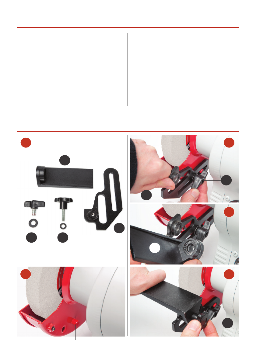
ASSEMBLY
1 2
C
B
D
3
B
ED
C
2
4
E
Locating pin
5
Continues Over...
Page 6
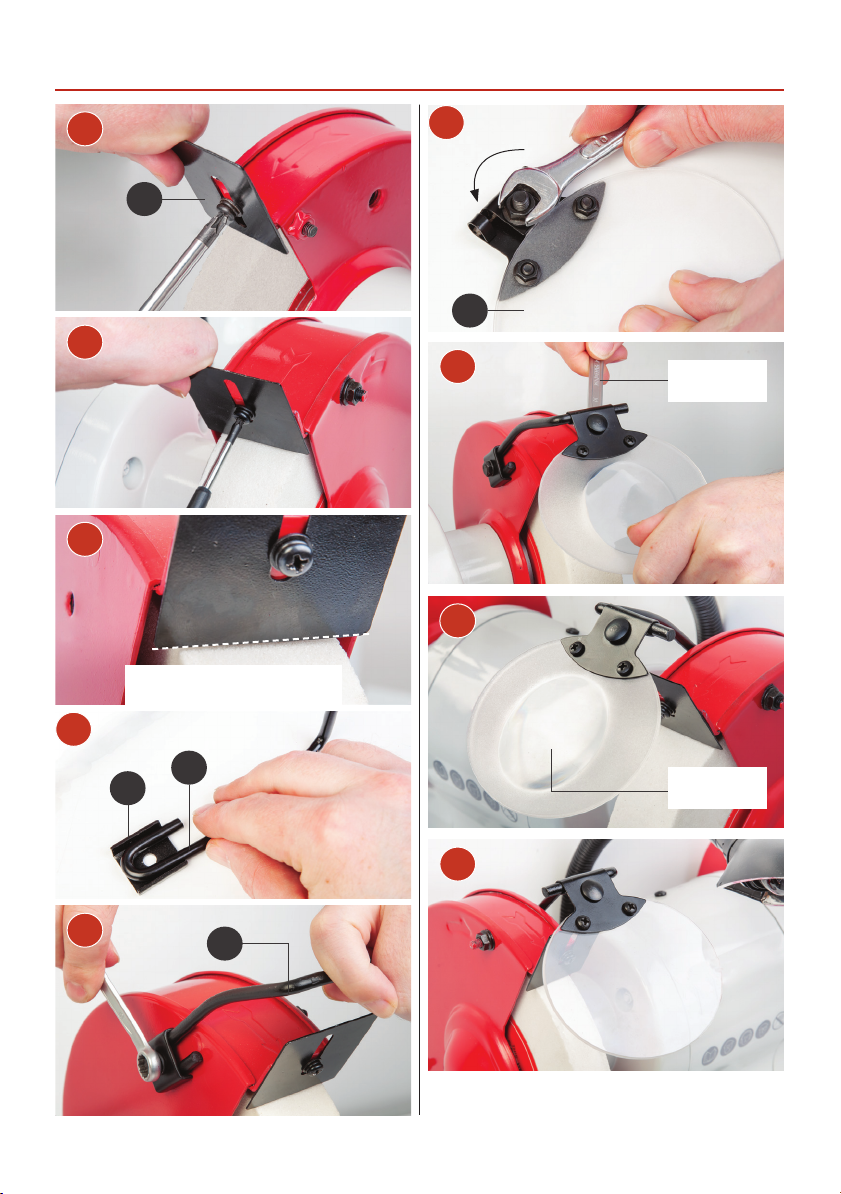
ASSEMBLY
5
F
6
7
Adjust the spark guard so its
just above the stone
10
11
12
I
Nip-up the
eye sheild
8
G
H
Magnifying
glass
13
9
G
6
Page 7
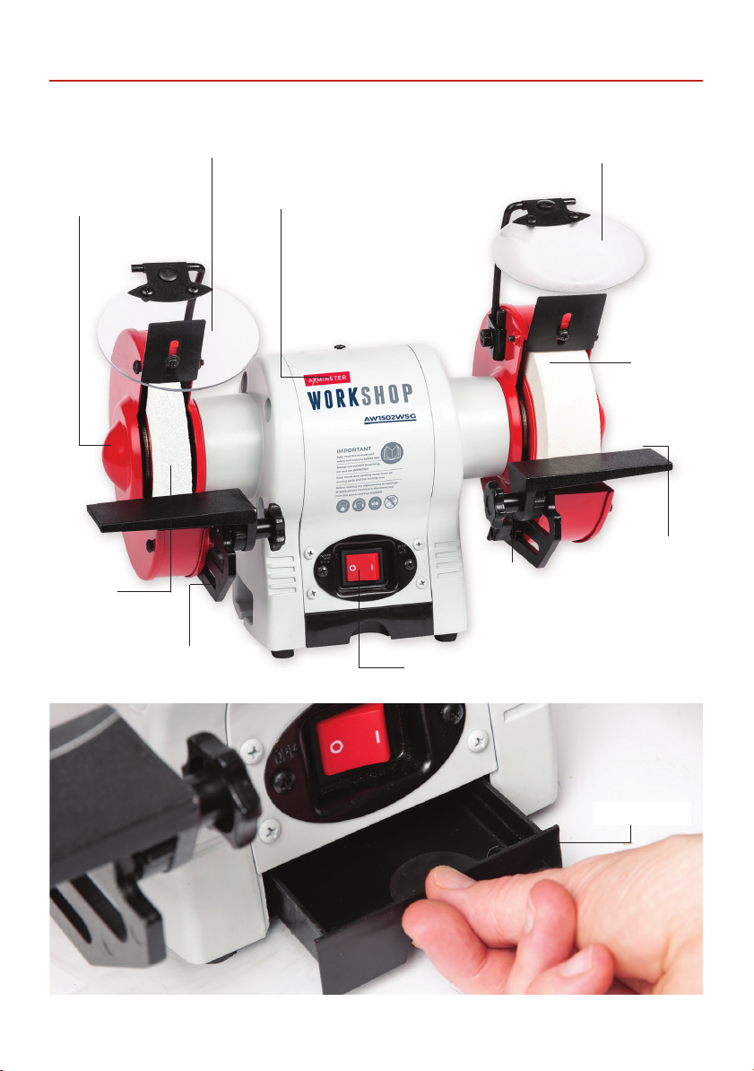
Eye shield guard
ILLUSTRATION AND PARTS DESCRIPTION
Eye shield guard
with integrated
magnifying glass
Grinding
stone guard
20mm
60 grit
Grinding
stone
Tool rest mounting
bracket
Motor
clamping bolts
On/Off switch
Tool rest
40mm
80 grit
Grinding
stone
Adjustable
tool rest
Storage drawer
7
Page 8
SPECIFICATION
SETTING UP THE GRINDER
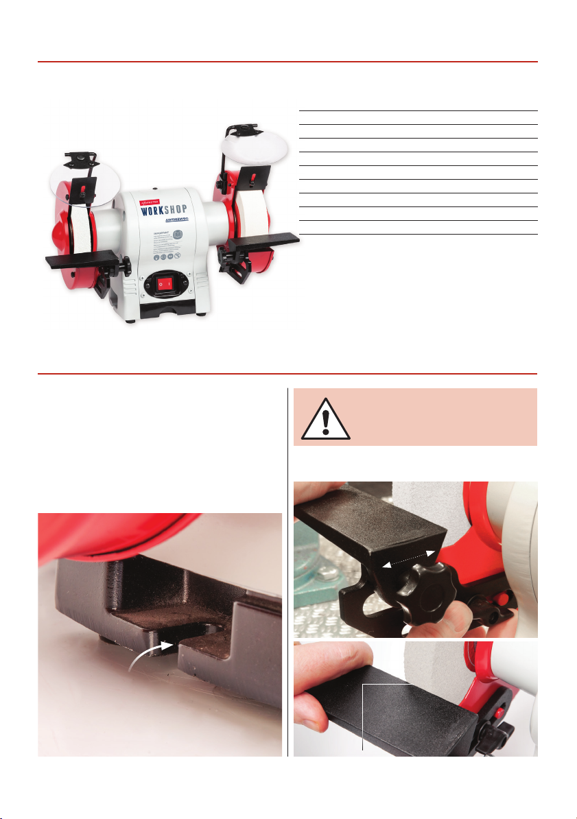
Place the grinder on a flat level surface. There are two
machined slots to either side of the grinder housing to
bolt the machine onto a work bench if required, see
fig 01.
Adjust the two tool rests leaving a gap of approximately
1.5mm clearance between the grinding stone and the
tool rest, see fig 02
Code 107824
Model AW1502WSG
Power 250W 50Hz 230V 1Ph
Duty Cycle S1 180W
Wheel Width 20 mm & 40 mm
Grit 20mm 60 grit & 40mm 80 grit
Wheel Diameter 150 mm
Shaft Diameter 12.7 mm (1/2")
Overall L x W x H 310 mm x 270 mm x 215 mm
Weight 9.8 kg
NOTE: ADJUST THE TOOL
RESTS AS THE GRINDING
STONE WEARS DOWN.
Fig 02
Fig 01
2mm
8
clearance
Page 9
Step 1-2
CONNECT THE GRINDER
TO THE MAINS SUPPLY.
ALWAYS WEAR EAR
DEFENDERS AND SAFETY
GOGGLES.
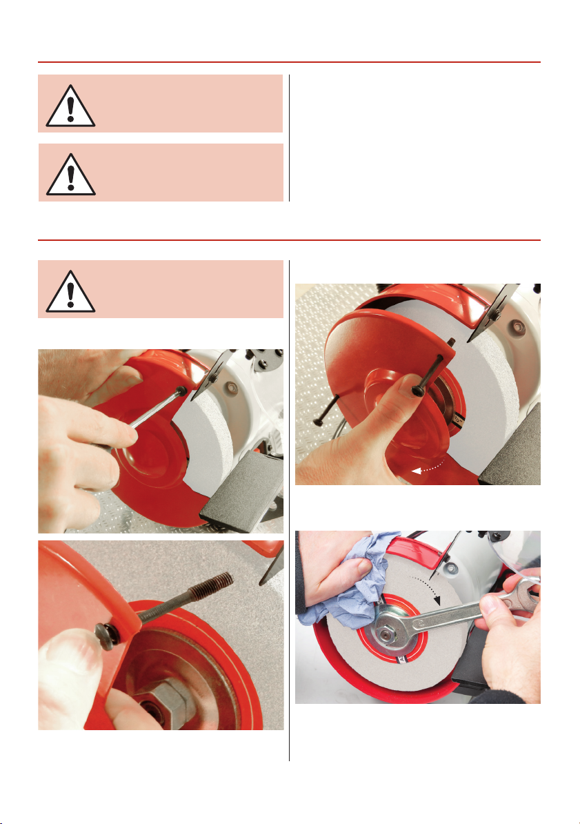
CHANGING THE GRINDING STONE
DISCONNECT THE GRINDER
FROM THE MAINS SUPPLY.
SETTING UP THE GRINDER
Carry out final checks e.g. check the gap between the
tool rest and the stone is correct, check the stone is
not badly deformed (rounded edges, grooved face, etc;
unless you have specifically shaped the stone to these
profiles), check the eye shield is correctly positioned.
Have a cooling pot to hand if you need it. Start the
machine, wait until it reaches full speed. Check it runs
smoothly, no knocking or scraping noises for example.
If all ok, switch off the grinder and wait until it comes
to a complete stop. Disconnect the machine from the
mains supply.
Step 3
Unscrew the three screws from the inner guard and
remove the outer stone guard cover. Place safely to
one side.
Grasp the stone using a cloth, use a 19mm spanner
to loosen the nut, remember undo the nut in the
direction of the stone’s rotation as indicated by the
arrow on the guard cover.
9
Continues Over...
Step 4
Page 10
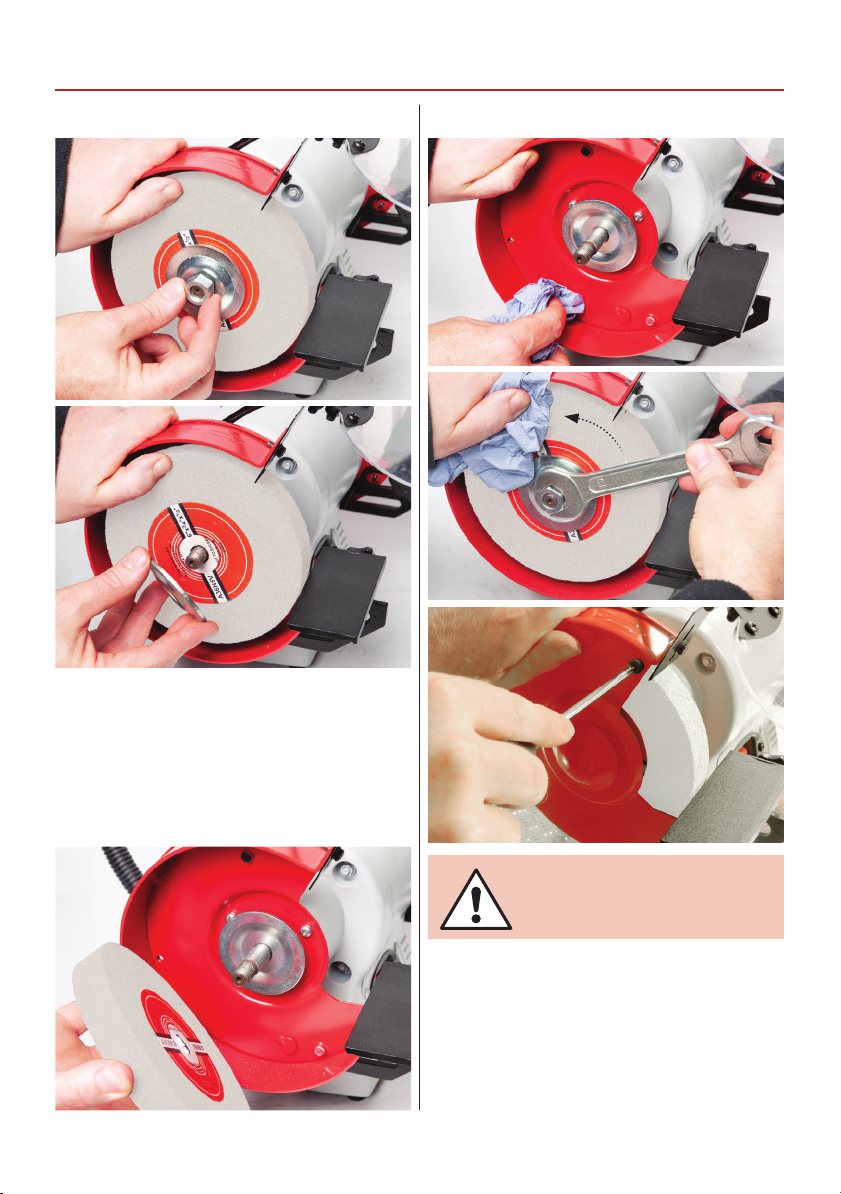
CHANGING THE GRINDING STONE
Step 5-6
Remove plate flange and carefully remove the stone.
Clean the interior stone guard, inspect the new stone
for cracks and damage to either the front face or the
edges before fitting. Carefully slide the stone on the
shaft, replace the plate flange, the nut and tighten
against the rotation of the stone. DO NOT
OVERTIGHTEN.
Step 8-9-10
Step 7
CONNECT THE GRINDER
TO THE MAINS SUPPLY.
Reconnect the grinder to the mains supply, give the
grinder a ‘short burst’, by switching it on and off
quickly. Check the grinder is not subject to any
undue vibration. If the grinder does vibrate, switch off
immediately and disconnect from the mains supply.
Remove the guard cover and check stone and plate
flange is fitted correctly. Check again, if the grinder
is still vibrating the stone/s may need dressing. Dress
the new stone lightly to ensure a ‘good face’ and good
concentricity.
10
Page 11
DRESSING THE STONECHANGING THE LIGHT BULB
CONNECT THE GRINDER
TO THE MAINS SUPPLY.
Switch on the grinder, wait until it reaches full speed
and leave the machine running for at least one minute
before carrying out any work. Apply a work piece and
check that the spark guard is correctly positioned and
that the tool rest is securely fixed. Switch off and wait
until the grinder comes to a complete stop.
DISCONNECT THE GRINDER
FROM THE MAINS SUPPLY.
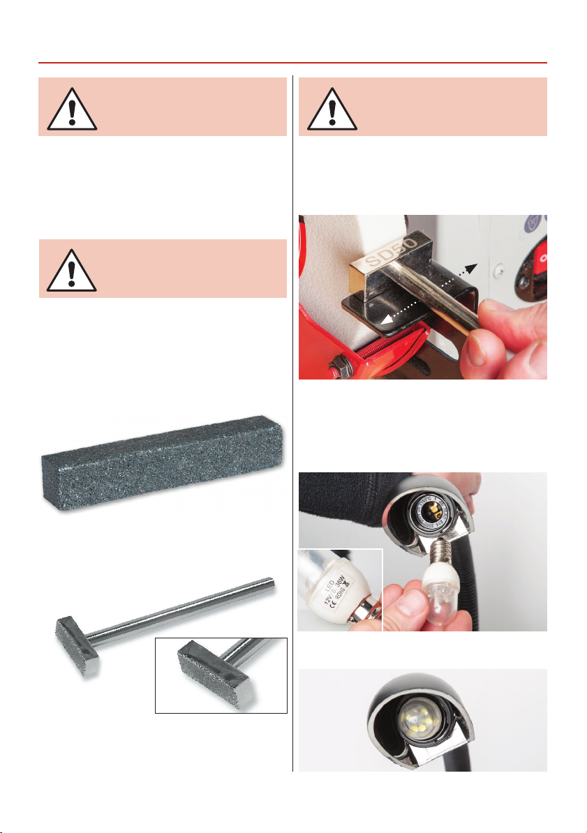
After a period of time uneven wear on the stones
including crests dips or rounded edges will appear.
They will need to be dressed out using a suitable wheel
dressing stick. See our website and in our catalogue for
details, see fig 10-11.
Fig 10-11
Code 410074
CONNECT THE GRINDER
TO THE MAINS SUPPLY.
Switch the grinder on and allow it to run for at least
one minute. Rest the dressing tool on the tool rest and
advance it to the stone until it touches the maximum
Fig 12
diameter; gently move the dresser back and forth
across the face of the stone until all irregularities have
been removed and the edges of the stone are nice and
sharp, see fig 12.
Changing the Light Bulb
Step 13-14
Wheel Dressing Stick for coarse carborundum
and dressing worn or unbalanced wheels.
Code 410057
Diamond Dressing Block useful for dressing across
the width of the grinding wheels or to produce flatter
surfaces than single point dressers.
The flexible light has a 12V 0.36W screw threaded LED
bulb. Unscrew the blown bulb and replace.
11
Page 12
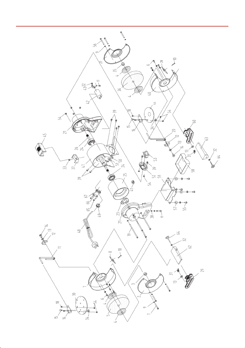
EXPLODED DIAGRAMSLISTS
Model: HBG620HA
12
Page 13

Model: HBG620HA
EXPLODED DIAGRAMSLISTS
No. Description Specification QTY
1 Type TZ Philips
screw
2 Left wheel guard
cover
3 Type I hex nut M12 Left 1
4 Flange 4
5 White wheel 150 x 20 x
6 Philips screw +
spring washer
assembly
7 Left wheel inner
cover
8 Left spark deflector 2
9 Spring washer D5 6
10 Philips screw +
spring washer + flat
washer assembly
11 Left eyeshield
support
12 Eyeshield support
fix plate
13 Flat washer D8 4
14 Hex bolt M8 x 14 2
15 Half round head
lower square neck
screw
M5 x 42 3
1
1
12.7mm 60#
M5 x 10 6
1
M5 x 8 2
1
2
M6 x 18 2
16 Eyeshield fix plate 2
17 Philips
screw+spring
washer+flat washer
assembly
18 Philips screw M4 x 10 4
19 Philips screw+flat
washer assembly
20 Right eyeshield
support
21 End cap 2
22 Type I hex nut M8 1
23 Wave washer D35 1
24 Bearing 180202 2
25 Stator 1
26 Rotor 1
27 Right wheel guard
cover
28 Right spark
deflector
29 Left fix work rest 1
30 Eyeshield 1
31 Locking knob M8 x 9 2
32 Flat washer D6 2
33 Philips screw M5 x 8 1
34 Hex flange face nut M6 2
M4 x 8 2
M5 x 124 4
1
1
1
13
Continues Over...
Page 14

EXPLODED DIAGRAMSLISTS
Model: HBG620HA
35 Nut M12 1
36 White wheel 150 x 40 x
37 Wheel dresser base 1
38 External teeth lock
washer
39 Cross pan head
screw
40 Right sheel inner
guard
41 Cable sleeve 1
42 Explosion-proof
capacitor
43 Capacitor stand 1
44 Eyeshield with
magnifier
45 Wheel dresser 1
47 Motor housing 1
48 Power cord with
plug
49 Cable clip 1
50 Nut M10 x 1 1
12.7mm 80#
D4 1
M4 x 8 10
6μF/450V 1
51 External teeth lock
washer
1
52 Switch plate 1
53 Switch 1
54 Hex flange face nut M4 8
55 Philips screw + flat
washer
56 Type TZ Philips
1
1
1
screw
57 Rubber foot 4
58 Coolant tray 1
59 Base 1
60 Right fix work rest 1
62 Left moveable work
rest
63 Right moveable
work rest
64 Locking knob for
work rest
65 Philips screw M4 x 16 2
67 Cable fix plate 1
D10 1
M4 x 16 4
M5 x 65 3
M6 x 21 2
1
1
14
Page 15
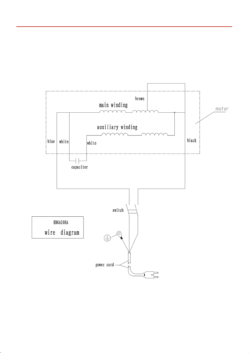
WIRING DIAGRAM
15
Page 16

For more information visit axminstertools.com/3years
The packaging is suitable for recycling.
Please dispose of it in a responsible manner.
EU Countries Only
Do not dispose of electric tools together with household waste material.
By law they must be collected and recycled separately.
Axminster Tools, Axminster Devon EX13 5PH
axminstertools.com
 Loading...