

Page 1
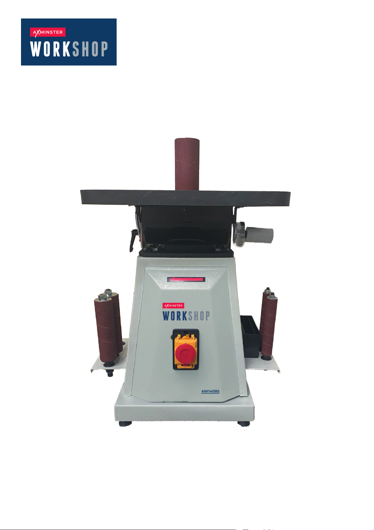
AW140BS
Bobbin Sander
Code 111879
Original Instructions
AT: 14/01/2025
Book Version: 02
Page 2
Signature:
Signed for and behalf of: Axminster Tool Centre Ltd; (place and date of issue): Axminster, Devon, United Kingdom Kingdom, 14/1/25 (name, function): Andrew Parkhouse, Supply Chain Direc tor
tools - Part 2: Immunity
Additional information:
risk reduction
tools - Part 1: Emission
References to the relevant harmonised standards used or references to the other technical
specifications in relation to which conformity is declared:
The object of the declaration described above is in conformity with the relevant EU legislation:
This declaration of conformity is issued under the sole responsibility of the manufacturer. Object of the declaration:
Product model: Axminster Workshop AW140BS Bobbin Sander
Name and address of the manufacturer: Axminster Tool Centre Ltd, A-201, Haagsche Hof, Parkstraat
83, The Hague, 2514 JG, Netherlands
Machinery Directive 2006/42/EC
EN 50370-2:2003 Electromagnetic compatibility (EMC) - Product family standard for machine
SO 12100:2010 Safety of machinery - General principles for design - Risk assessment and
EN 50370-1:2005 Electromagnetic compatibility (EMC) - Product family standard for machine
Name and address of person authorised to compile the technical file: Axminster Tool Centre
Ltd, A-201, Haagsche Hof, Parkstraat 83, The Hague, 2514 JG, Netherlands. The machinery fulfils all relevant provisions of Supply of Machinery (Safety) Regulations 2008
as amended.
EMC Directive 2014/35/EU
Axminster Tool Centre Ltd
EC DECLARATION OF CONFORMITY
‘original’
References to the relevant harmonised standards used or references to the other technical
specifications in relation to which conformity is declared:
Signature:
(name, function): Andrew Parkhouse, Supply Chain Director
Additional information:
tools - Part 1: Emission
tools - Part 2: Immunity
Signed for and behalf of: Axminster Tool Centre Ltd;
(place and date of issue): Axminster, Devon, United Kingdom, 14/1/25
risk reduction
Object of the declaration:
The object of the declaration described above is in conformity with the relevant GB legislation:
Axminster, Devon EX13 5PH, United Kingdom
This declaration of conformity is issued under the sole responsibility of the manufacturer.
Product model: Axminster Workshop AW140BS Bobbin Sander
Name and address of the manufacturer: Axminster Tool Centre Ltd, Unit 10 Weycroft Avenue,
Supply of Machinery (Safety) Regulations 2008 as amended.
Electromagnetic Compatibility Regulations 2016 as amended.
Name and address of person authorised to compile the technical file: Axminster Tool Centre
Ltd, Unit 10 Weycroft Avenue, Axminster, Devon EX13 5PH, United Kingdom
The machinery fulfils all relevant provisions of Supply of Machinery (Safety) Regulations 2008
as amended.
EN 50370-2:2003 Electromagnetic compatibility (EMC) - Product family standard for machine
ISO 12100:2010 Safety of machinery - General principles for design - Risk assessment and
EN 50370-1:2005 Electromagnetic compatibility (EMC) - Product family standard for machine
Axminster Tool Centre Ltd
UK DECLARATION OF CONFORMITY
‘original’
2
Page 3

CONTENTS
Section Page
Contents 3
Technical Specification 3
Safety Instructions 4-5
Specific Safety Instructions 6
Getting to Know the Machine 7
Assembly and Setting Instructions 8-9
Operating Instructions 10-11
Wiring Diagram 11
Parts List & Diagram 12-15
AW140BS
TECHNICAL SPECIFICATION
Motor Capacity 1/2Hp, 370 Watt
Voltage 230V, 50 Hz
No load speed 1400 rpm
Work table size 370 x 370 mm
0
Work table tilt 0
Bobbin size
Bobbin travel 24 mm
Sanding drums (5)
1/2” 3/4” 1” 1-1/2” 2”
– 45
0
Sound power level: no load
with load
Sound pressure level: no load
with load
80 dB
78 dB
69.6 dB
65.9 dB
3
Page 4

SAFETY INSTRUCTIONS
The following safety information is a mandatory
requirement as detailed in BS EN 61029-1:2000 safety
of transportable motor-operated electric tools Part
1: General requirements and EN 50144-1:1995 Safety
of hand-held motor-operated tools Part 1: General
requirements.
All power tools should be kept out of the reach of
children, preferably stored or locked in a secure
cabinet or room when not in use.
DO NOT FORCE THE POWER TOOL
The power tool will be do a better and safer job and
give you much better service if it is used at the rate
for which it was designed.
GENERAL SAFETY INSTRUCTIONS
Read and understand all these instructions before
attempting to operate this product and keep them in
a safe place for future reference.
“WARNING!” When using electric power tools the
following basic safety precautions should always be
followed to reduce the risk of fire, electric shock and
injury.
SAFETY INSTRUCTIONS
Before attempting to operate this machine, it is
important that you read, understand and follow
these instructions very carefully. They are designed
for the safety of yourself and others ensuring a long
and trouble free service life from your machine.
SAFE OPERATION
KNOW YOUR POWER TOOL
It is important that you read and understand our
instruction manual and any label attached to the
power tool. Learn its applications as well as its
limitation and the potential hazard associated
with this power tool.
WORK AREA
Cluttered benches and work areas invite accidents.
Workbenches should be kept tidy. Floors should
be kept clean and free from rubbish. Special care
should be taker where the floor is slippery due to
sawdust or wax.
WORK ENVIRONMENT
Do not expose your power tool to rain, or use in damp
or wet locations. Keep the work area well lit .Do not
use power tools in areas where is a risk of explosion or
fire from combustible materials, flammable liquids,
paint, varnish, petrol etc. flammable gases and dust
of an explosion nature.
As a precaution it is recommended that you consult
an expert on a suitable fire extinguisher and its use.
GUARD AGAINST ELECTRIC SHOCK
Avoid body contact with earthed or grounded
surfaces (e.g. pipes, radiators, ranges, and
refrigerators).
BEWARE CHILDREN AND PETS
Children and pets should be kept out of the work
area. Children not be allowed to touch or operate
machinery or touch extension cords.
USE THE RIGHT TOOL
Select the right tool for the job .Do not use a tool for
a job for which it was not designed. Do not force a
small tool to do the job of a heavy-duty tool. Do not
use tools for purposes not intended; for example do
not use a circular saw to cut tree limbs or logs.
PERSONAL SAFETY CLOTHING
Do not wear loose clothing, jewellery or anything that
could get caught in moving machinery.
HAIR
Long hair should be tied back or contained in
a protective covering.
EYE PORTECTION
The use of safety goggles is a mandatory
requirement (normal glasses are not sufficient for
eye protection). Prescription spectacles do not have
safety lenses.
FOOTWEAR
Where there is a risk of heavy objects damaging feet
or if there is a risk of slipping on wet or slippery floors
suitable non-slip safety footwear should be worn.
HEAD PROTECTION
Where there is a risk of falling objects or hitting your
head on protruding or low level obstructions a hard
hat should be worn.
RESPIRATORY PROTECTION
When the machining operation creates dust wear a
dust mask. When machining concrete, man made
fibre boards, especially MDF(Medium Density Fibre
Board) the resin used in these materials can be
hazardous to your health. Use an approved face mask
with replaceable filter.
DUST EXTRACTION EQUIPMENT
If the machine is fitted with dust extraction and
collection facilities ensure that these are properly
connected and used.
DO NOT ABUSE THE POWER CORD
Never yank or pull on the power cord to disconnect it
from the mains supply socket.
Never carry your power tool by its power cord. Keep
the power cord away from heat, oil, solvents and
sharp edges. If the power cord becomes damaged
have it replaced by an authorized service facility.
4
Page 5

SECURE THE WORK PIECE
Wherever possible secure the work piece using
clamps or a vice. It is safer than using your hand and
leaves both hands free to control the power tool.
DO NOT OVER-REACH
Do not over-reach, keep proper footing and maintain
your balance at all times.
Pretect your extension cord from sharp objects,
excessive heat and damp or wet locations,
STAY ALERT
Watch what you are doing, use common sense.
And do not operate the power tool when you are
tired, if taking medication that causes drowsiness,
when having consumed alcohol or taken drugs.
MAINTAIN TOOLS WITH CARE
Keep cutting tools sharp and clean for better and
safer performance.
Follow the instructions for lubricating and changing
accessories.
Check the tool power cord periodically and if
damaged have it replaced by an authorized service
facility.
Inspect extension cords periodically and if damaged
replace it.
Keep handles dry clean and free from oil and grease.
Ensure that ventilation slots are kept clean and free
from dust at all times. Blocked ventilation slots can
cause overheating and damage to the motor.
DISCONNECT POWER TOOLS
Ensure that power tools are disconnected before
semicing Lubricating or minus, adjustments and
when changing accessories such as blades, bits
and cutters.
CHECK DAMAGED PARTS
Before using the power tool it should be carefully
checked to determine that it will operate properly
and perform its intended function.
Check for the correct alignment of moving parts
ensuring they do not bind. Check for broken or
missing parts and have them replaced or repaired
at an authorized service center.
If the power tool requires mounting make sure it is
securely attached to a suitable work bench .Check
any other condition that may affect the operation
of the power tool.
A guard or any other part of the power tool that is
damaged should be properly repaired or replaced
by an authorized service center unless otherwise
indicated in this instruction manual.
Any switch that does not operate correctly must be
replaced by an authorized service center.
Do not use the power tool if the ON/OFF switch does
not turn the power tool ON and OFF.
REMOVE ADJUSTING KEYS
AND WRENCHES
Form the habit of always checking to see that keys
and adjusting wrenches are removed from the
power tool before turning it on.
AVOID UNINTENTIONAL STARTING
Ensure that the switch is in the OFF position before
plugging the power tool into the mains supply.
EXTENSION CORDS AND REELS
Do not use 2 core extension cords or reels on
power tools with an earth path. Always use a 3 core
extension cord or reel with the earth core connected
to earth.
When the power tool is to be used outdoors,
use only extension cords intended for outdoor
use and are so marked,
Always unwind any extension cords fully.
For extension cords up to 15 meters use a wire
cross section of 1.5mm2.
For extension cords over 15 meters but less than
40 meters use a wire cross section of 2.5mm2.
WARNING!
Do not attempt to modify the power tool in any way.
The use of any attachment or accessory other than
those recommended in this instruction manual could
result in damage to the power tool and injury to the
operator.
Have your power tool repaired by a qualified person.
This electric power tool complies with national and
international standards and safety requirements.
Repairs should only be carried out by qualified
persons to do so may result in considerable danger
to the user.
PROTECT FURNISHINGS
If using the power tool inside your house protect
furnishings with a suitable dust.
FIRE PRECAUTIONS
When using certain power tools your house or
workshop general fire precautions should be
observed. As a Precaution, it is recommended that
an expert is consulted on obtaining and using a
suitable fire extinguisher.
Always replace a damaged extension cord
before using it.
5
Page 6

SPECIFIC SAFETY
Always start sanding with a coarse grade of sanding
drum working through the grades to the finest grade.
INSTRUCTIONS
EXTREME CAUTION REQUIRED
Be aware that the paint on old wood could contain
high levels of lead. Extreme care should be taken
when sanding painted surfaces. The dust may
contain LEAD which, if touched, ingested or inhaled
will cause poisoning and can be fatal.
Any pre 1960’s building may have had paint containing
lead on wood or metal structures and surfaces.
STOP!
If you suspect paint in your house contains lead seek
professional help.
Once lead is in the body it is retained until a fatal level
is reached. Small amounts of exposure can cause
irreversible brain and nervous system damage. The
young and unborn are particularly at risk.
WARNING!
Some wood and type products especially MDF
(Medium Density Fibre-board) can produce dust that
can be hazardous to your health. We recommend the
use of ar approved face mask with replaceable filters
when using this machine in addition to using the
dust extraction facility.
Never try to modify the machine or fit accessories
other than those recommended in this manual.
Regularly clean the machine and remove any build
up of sawdust inside and around there hazing.
A build up of sawdust can be Never leave the
machine unattended while it is still running.
TIP
An acceptable filler which could be a good colour
match can be made by mixing the sanding dust
with PVA glue.
Ensure that power tools are disconnected from the
mains supply when not in use, before servicing,
lubricating or making adjustment and when
changing accessories such as table inserts and
sanding belts.
This machine has been designed for sanding wood,
wood type products and plastics. It must not be used
for sanding metal as the sparks could ignite sawdust
and wood shavings.
It is not recommend that this machine be used for
sanding fiberglass or similar materials as the particles
generated can cause under ware on bearings etc.
Do not attempt to use for sanding operations as a
fatal electric shock could occur. This machine is to be
use for dry sanding only.
Ensure that the sanding drum is the correct size for
the bobbin being used.
Do not start the machine whilst it is in contact whit
the work piece.
Check the work piece for any protruding nails, screw
heads or anything that could tear or damage the
sanding drum.
Replace the sanding drum as soon as it becomes
worn or if it is torn, torn sanding drums can cause
deep scratches that are difficult to remove.
6
Page 7
GETTING TO KNOW
YOUR MACHINE
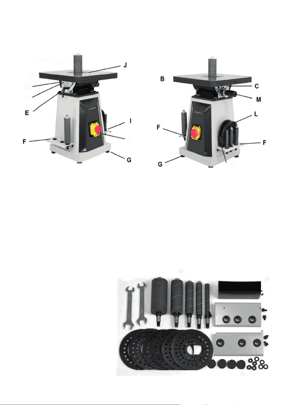
A Spindle with Sanding Sleeve
B Work Table
C Dust Port
D Cam for Table Leveling
E Table Angle Scale and Locking Handle
F Holder for Spindles
G Rubber Feet (4)
CONTENTS OF PACKAGE
Wrenches (2) - 14mm, 17mm
Table Inserts (6)
Rubber Feet (4) & Hardware
Tool Holders for Drums (2) & Hardware
H ON / OFF Safety Switch
I Holder for Spindles
J Table Insert (installed in table)
K Holder for Table Inserts
L Table Inserts
M Geared Handle with Lock for Tilting Table
Holder for Table Inserts & Screws
Sanding Drums (5) - 1/2” 3/4” 1” 1-1/2” 2”
Manual & Warranty Card (not shown)
7
Page 8
ASSEMBLY
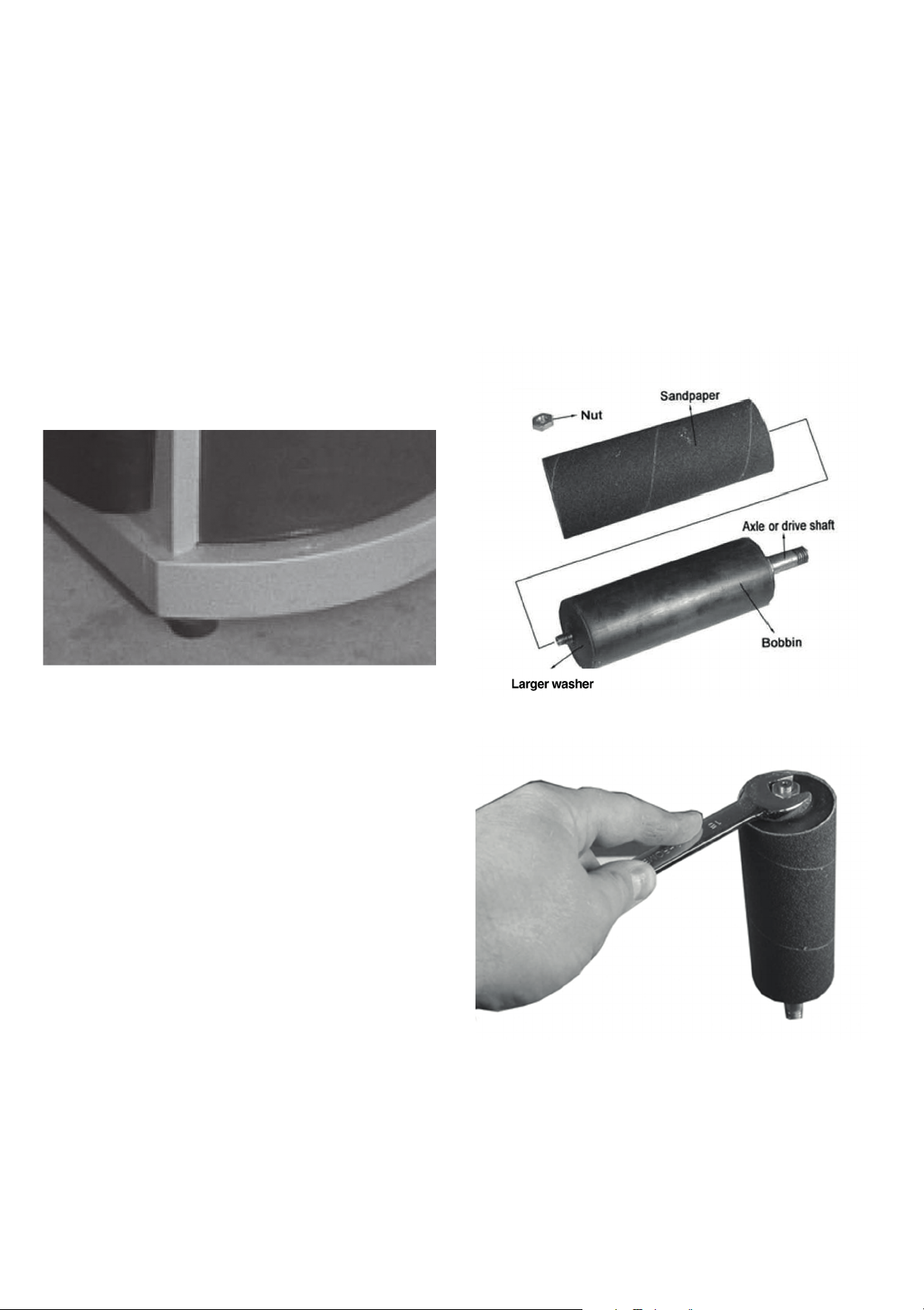
Larger washer (Fig 2)
CAUTION: THE MACHINE IS HEAVY AND
MAY REQUIRE TWO PERSON LIFTING
Remove the Bobbin Sander from the packaging. The
machine comes ready assembled apart from the
sanding attachments and the rubber feet.
ATTACHING THE RUBBER FEET
Lower the machine onto its side. Remove the feet
from the plastic wrapping.
Remove the nut and washer from the thread.
Locate the four mounting points on the underneath
of the machine. Insert the thread into the hole so that
the rubber foot points downward (fig 1 ).
The bobbin consists of a rubber body with a metal
axle passing through the center (fig2). The axle has a
key which locates into a keyway in the rubber body.
Normally these should need not be disturbed unless
the rubber body is damaged.
At either end of the body are two large compression
washers.
At the top is a nut and washer to secure the
cylindrical sandpaper. The low part of the axle is
threaded which locates into the motor drive.
Fig 1
Put on the washer followed by the nut.
Tighten with a spanner. Repeat operation for the
other three feet.
Site the machine at a suitable height enabling
sanding operation to be carried out comfortably
and in a safe manner.
TO INSTALL THE
SANDPAPER
CAUTION: MAKE SURE THE MACHINE IS
ISOLATED FROM THE SUPPLY BEFORE
ANY MAINTENANCE, CLEANING OR
ADJUSTMENTS ARE UNDERTAKEN.
The sander has been supplied with 5 set rubber
cylinder or bobbins (fitted with sanding drum
installed).
If you want to change the grade of sanding paper
already attached to the bobbins proceed as shown.
Fig 2
Fig 3
Remove the nut using a suitable spanner (fig 3), lift
away the washer and slide the sanding drum clear of
the bobbin.
If removal was difficult sprinkle a small amount of
talcum powder onto the rubber to aid fitting the new
sandpaper drum.
8
Page 9
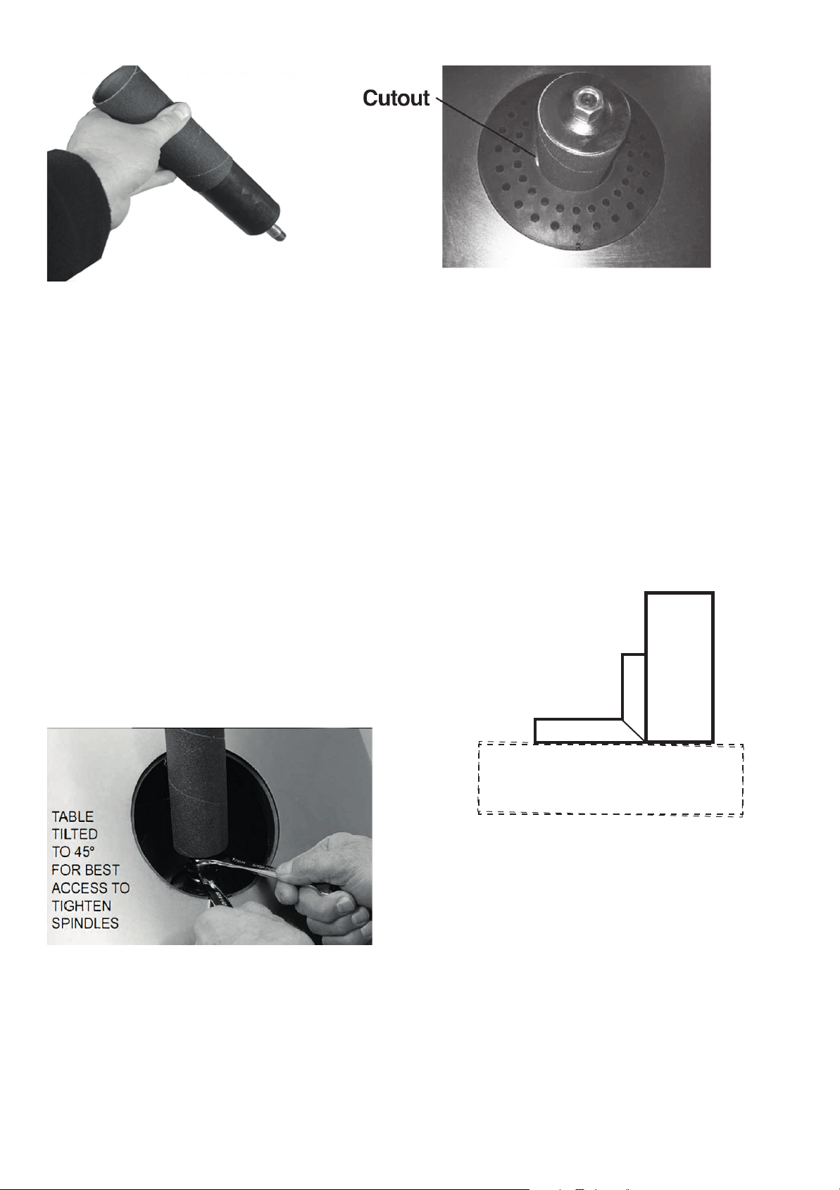
Fig 4
Various grades of sanding drum are available for
different jobs. See your stockist for replacement
of sanding drum.
Offer the sanding drum to the rubber body (fig4).
Slide onto the rubber body so it fits centrally with
no edge overhanging.
Replace the washer and nut. With a spanner tighten
the nut to expand the rubber body. This will grip the
sanding drum. Do not over-tighten as this will distort
rubber body.
INSTALLING THE BOBBIN ONTO THE
MACHINE
Lower the bobbin down through the top of the
machine.
Locate the thread on the bobbin spindle into the
thread on the motor drive spindle.
Hold the motor drive spindle with your hand and
tighten the bobbin into the motor drive spindle.
Fig 6
Notice the cutout on the edge of the table insert. This
aligns the peg in the recess on the table (fig 6). Lower
into position making sure the table insert locates in
the recess and is flush with the table.
To remove simply push with your finger from
underneath to dislodge the table insert.
CHECKING THE TABLE TOP ALIGNS
WITH ZERO DEGREES
The table top has the facility to tilt between 0°and 45°.
NOTE: Check that the table is set to 0° with respect to
the bobbin. Using a suitable 90° square placed on the
table top, move the square to the bobbin.
It should measure 90
0
(fig 7).
Select two open ended spanners (fig 5).
Fig 5
With one spanner hold the motor drive tighten the
bobbin spindle. Do not over-tighten.
SELECTING TABLE INSERT
The machine comes with two table inserts. There is
one with a round cutout and one with oval cutout.
For normal sanding choose the insert with the
round cutout (fig 6).
Fig 7
If the table is not square an adjustment can be made.
Located under the work table is a stop bolt which
adjusts the level of the table (fig 8).
Loosen the lock nut and raise or lower the stop bolt.
Take note of when table is at go0 with the bobbin.
Tighten the lock nut.
Locate the pointer and scale. Slacken the pointer
screw. Align with the 0° position on the scale and
re-tighten screw.
9
Page 10
OPERATING
INSTRUCTIONS
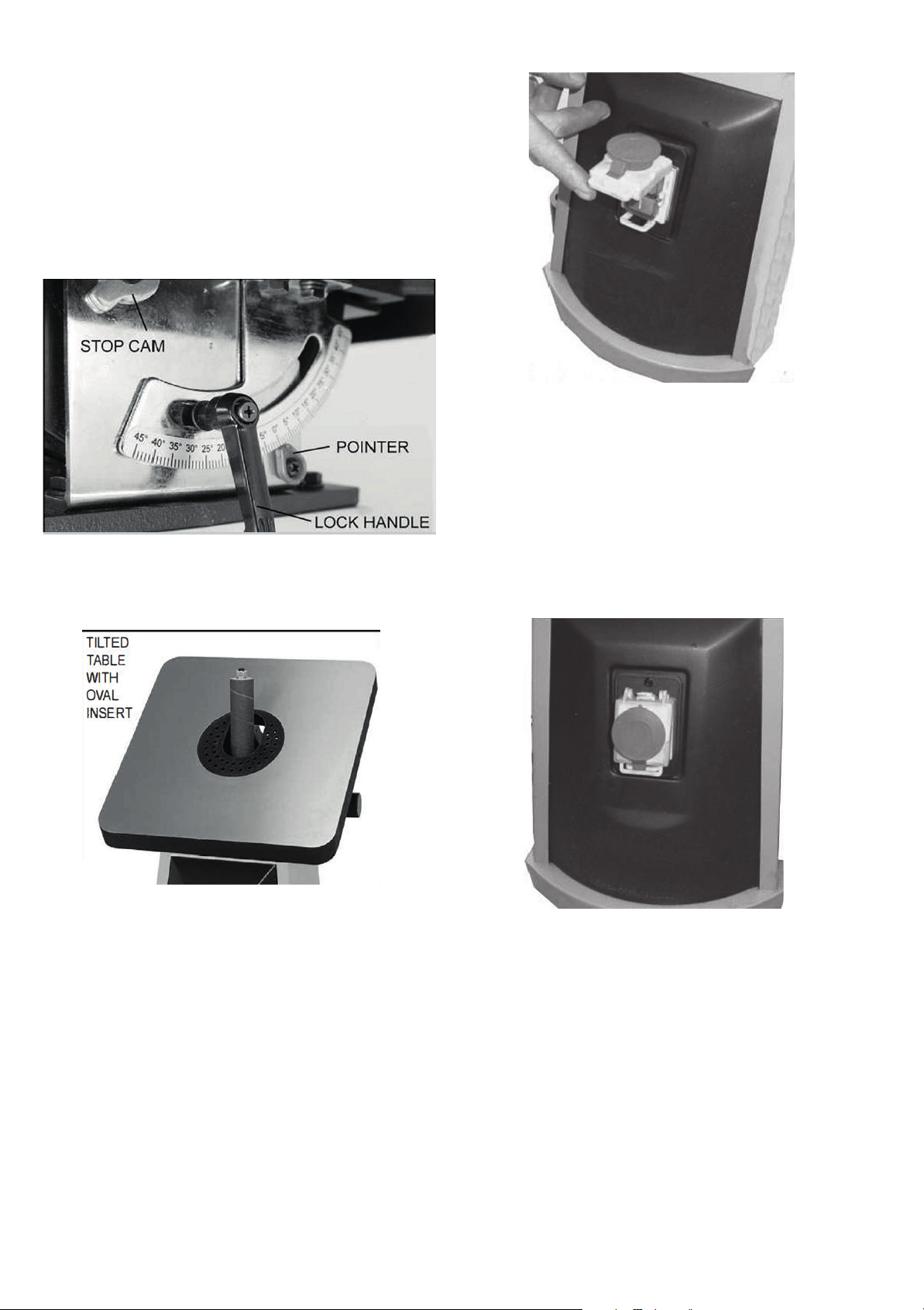
TILTING THE TABLE
NOTE: Remove the table insert with the round cutout
before tilting the table otherwise it will break.
The table will tilt 0° - 45° . Once the desired angle has
been reached tighten the two locking knobs (fig 8).
Fig 10
EMERGENCY STOP BUTTON
This is the large red button (fig 11 ). Simply hit the
button and the machine will stop.
There is no need to I ift the cover to access the stop
button underneath.
Fig 8
Locate the table insert with the oval cutout and
place into the table top (fig 9).
Fig 9
STARTING AND STOPPING
The machine is with a no volt switch. In the event of a
power failure, the motor will not start once the power
is restored.
Located on the front of the machine is the ON/OFF
button incorrporating the emergency stop button.
Insert the machine plug into a suitable 13 amp outlet
socket.
Lift the emergency stop cover to reveal the ON/OFF
buttons (fig 10).
Press the green button to start. Close the emergency
stop cover. Do not close by pushing the large red
button as the motor will stop.
To start the machine see starting and stopping.
In the event of power failure the machine will not
restart when the power is restored.
Fig 11
USING THE BOBBIN SANDER
Start the machine and wait the motor has build up
to full speed. It can be seen that the MM326C bobbin
moves up down traveling 24mm and MM326D is
30mm in total.
CAUTION: NEVER START THE MACHINE WITH WORK
IN CONTACT WITH THE BOBBIN
Looking from the front of the machine the motor
turns in a clockwise direction (fig 12).
Feed the work across and with the direction of
rotation.
10
Page 11
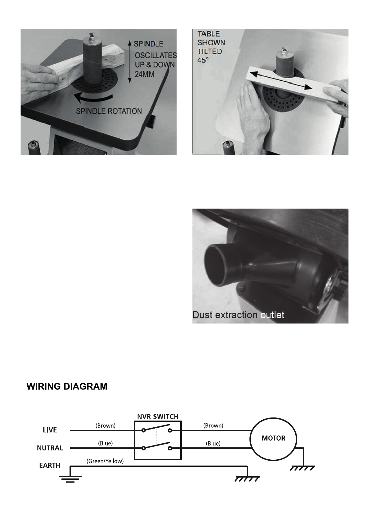
Fig 12
Dust extraction outlet
fig 14
Fig 13
USING THE BOBBIN SANDER
AT ANGLES 0° • 45°
NEVER feed the work into the machine and stand
with your body directly behind it. The machine
could force the work into the operator and cause
serious injury.
Take out the round insert and store carefully. Put in
the oval insert (refer to selecting table insert, page 10)
Slacken the table securing knobs either side of the
machine.
Tilt the table to the desired angle and re-tighten
the locking knobs.
Feed the work into the machine always with the
direction of rotation (fig 13).
NOTE: Always bear in mind that when the table
is tilted to a particular position the angle will only
remain constant if the work is run parallel to the
bobbin.
Fig 14
DUST EXTRACTION
The machine is fitted with a 50mm diameter dust
extraction outlet. This is located at the rear of the
machine (fighting 14) and should be attached to a
suitable extractor / collector.
11
Page 12
PARTS LIST
W140B
11A
12
Page 13
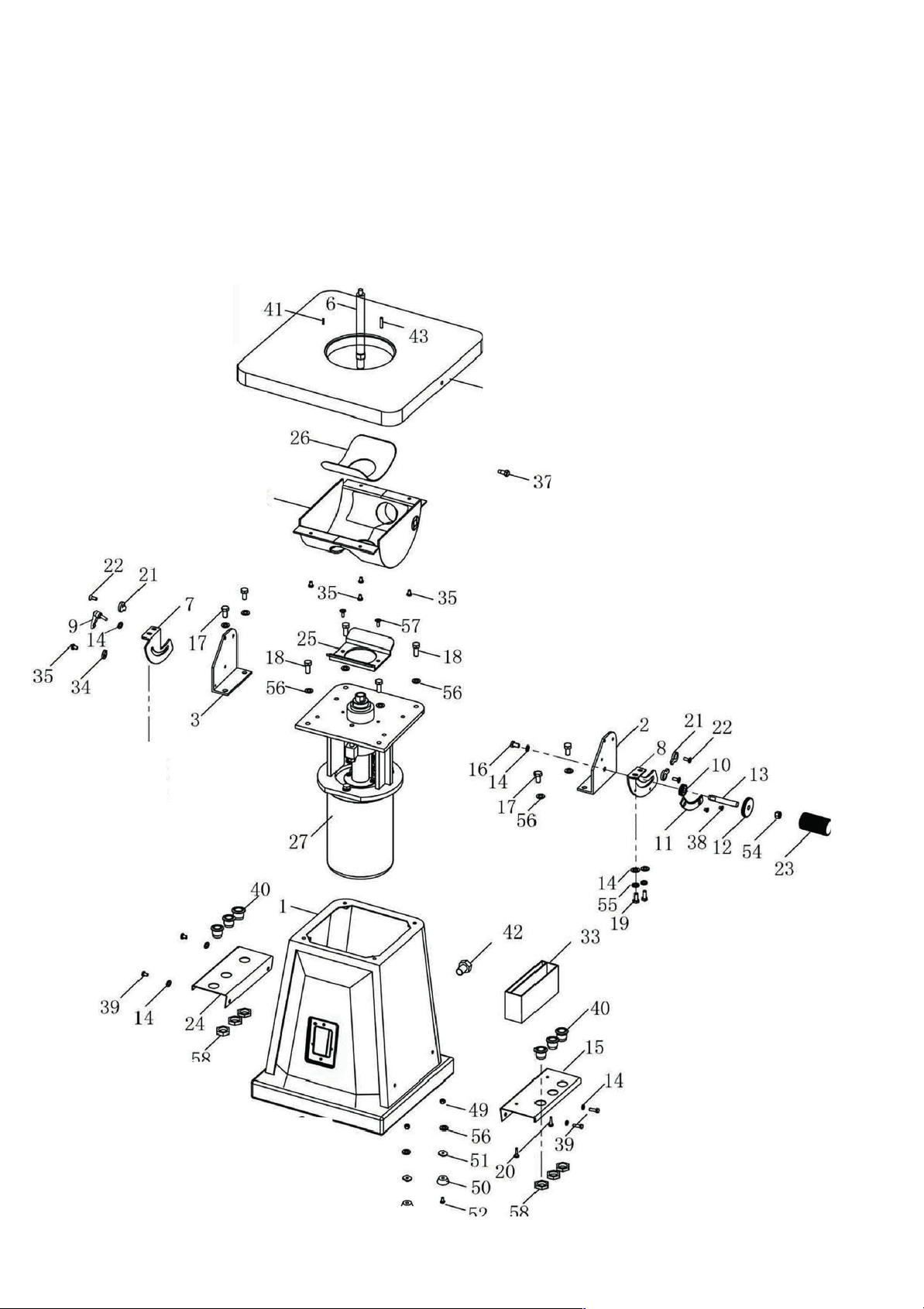
37
36-.
DIAGRAM A FOR A
W140BS
:
9
13
Page 14

PARTS LIST FOR A
;
o
,
6
t
6
s
6
I
L
_
35
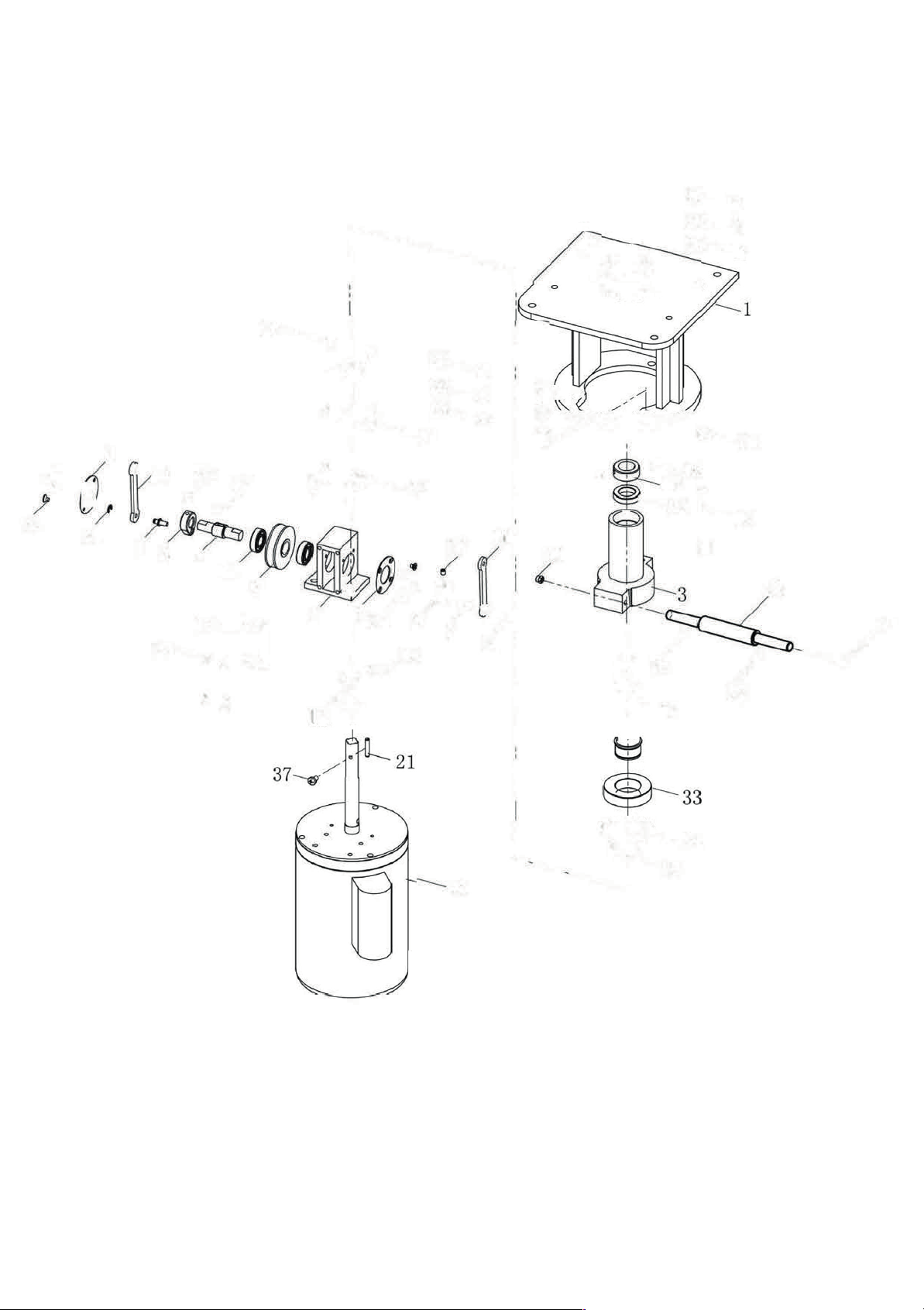
W140
BS DIAGRAM B:
KEY
14
Page 15
6
;
s
6
,
o
I
6
t
L
_
35
15
Page 16

The packaging is suitable for recycling.
Please dispose of it in a responsible manner.
EU Countries Only
Do not dispose of electric tools together with household waste material.
By law they must be collected and recycled separately.
Axminster Tools, Axminster Devon EX13 5PH
axminstertools.com
For more information visit axminstertools.com/3years
 Loading...