

Page 1
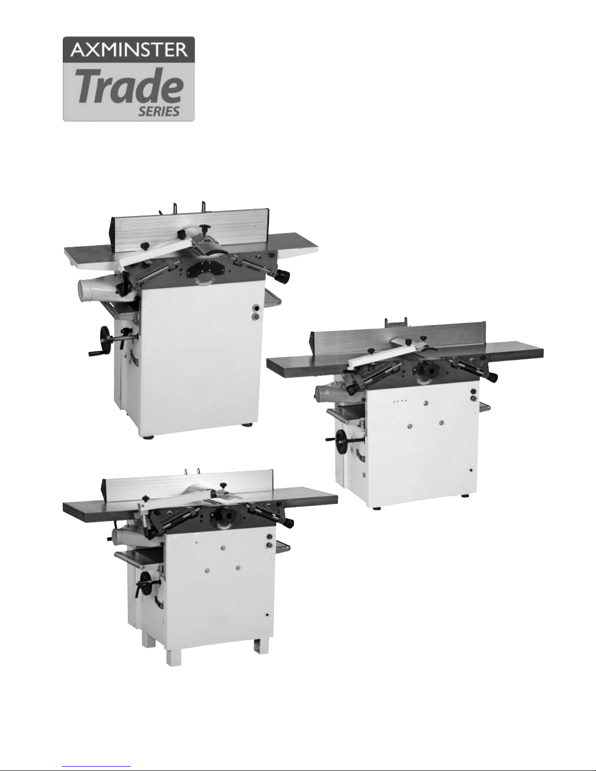
AW106PT2 AW128PT &
AW168PT Planer/Thicknesser
Axminster Tool Centre,
Unit 10 Weycroft Avenue, Axminster, Devon EX13 5PH
axminster.co.uk
Code: 501202
Code: 501203
Code: 501204
501203
(AW128PT)
501202
(AW106PT2)
501204
(AW168PT)
Page 2
02
Index of Contents
Page No.
Index of Contents 02
Declaration of Conformity 02
What’s Included 03
General Instructions for 230V Machines 03-04
Specific Precautions Using Planer Thicknessers 04-05
Specifications 05
Initial Assembly and Setting Up 06-07
Machine Illustration and Parts Description 08-09-10-11
Operating Illustrations 12-13
Changing the Planer Blades 14-15-16
Routine Maintenance 17-18-19
Parts List/Drawing 1 (AW106PT2) 20-21
Parts List/Drawing 2 (AW106PT2) 22-23
Parts List/Drawing 3 (AW106PT2) 24-25
Parts List/Drawing 4 (AW106PT2) 26
Parts List/Drawing 1 (AW128PT-AW168PT) 27-28
Parts List/Drawing 2 (AW128PT-AW168PT) 29-30
Parts List/Drawing 3 (AW128PT-AW168PT) 31-32
Parts List/Drawing 4 (AW128PT-AW168PT) 33
Notes 34-35
Copied from CE Certificate
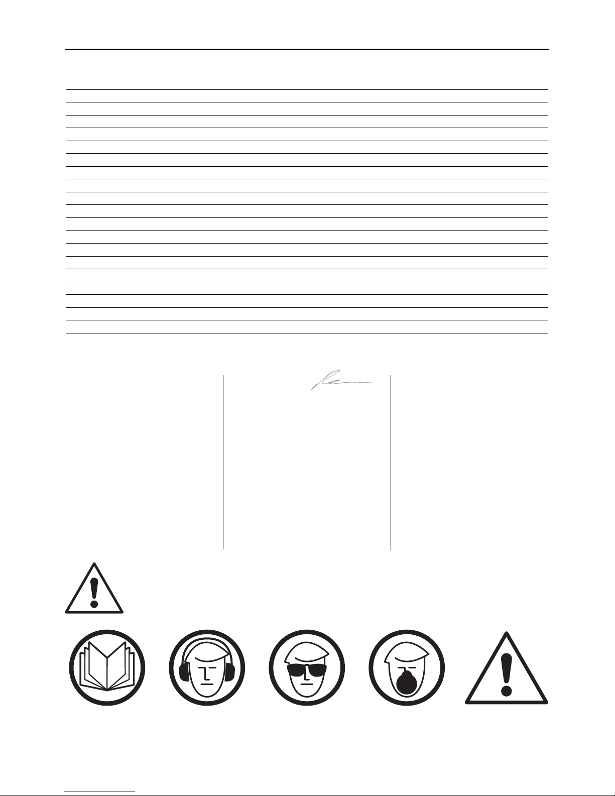
Warning
The symbols below advise that you follow the correct
safety procedures when using this machine.
Dust mask
should be worn
Ear protection
should be worn
Eye protection
should be worn
Fully read manual
and safety instructions
before use
HAZARD
Motor gets hot
The undersigned, F.Recherburg
authorised Laizhou Planet Machinery
Co., Ltd. No. 989. North Laizhou Road
261400 Laizhou Shandong
P.R.China declares that this product:
manufactured by Laizhou Planet
Machinery Co. is in compliance with
the following standards or
standardisation documents EC
Directive 98/37/EC Artlcle 8, section
2b Machinery in accordance with the
Council Directive 98/37/EC.
ML392
The undersigned,
authorised Laizhou Planet Machinery
Co., Ltd. No. 989. North Laizhou Road
261400 Laizhou Shandong
P.R.China declares that this product:
manufactured by Laizhou Planet
Machinery Co. is in compliance with
the following standards or
standardisation documents EC
Directive 98/37/EC Artlcle 8(2)b, or
Article 8(2)c, Machinery in
accordance with the Council
Directive 98/37/EC.
ML393
The undersigned, G. Reimann
authorised Laizhou Planet Machinery
Co., Ltd. Yutai West Street, Laizhou,
Shandong 261400 P.R.China declares
that this product:
manufactured by Laizhou Planet
Machinery Co. is in compliance with
the following standards or
standardisation documents
2006/95/EC
ML394Q/C2-410Q
Page 3
03
What’s Included
Model Numbers: ML392-ML393 (501202 & 501203) ML394Q/C2-410Q (501204)
1 No. AW106PT2 / AW128PT / AW168PT Planer Thicknesser (95% assembled)
1 No. Planer Fence
1 No. Planer Fence Mounting Base
1 No. Fence Securing Bracket
1 No. Overhand Planer Guard Mounting Bracket
1 No. Overhand Planer Guard
1 No. Overhand Planer Guard Locking Plate
1 No. Spring Metal Plate
2 No. M10 Washers
2 No. M10 Lever Handle Bolts
2 No. M6 x 12mm Caphead Bolts
1 No. 3mm Allen Key
1 No. 4mm Allen Key
1 No. 5mm Allen Key
1 No. 6mm Allen Key
2 No. M6 Eye Bolts (for lifting)
1 No. 7mm x 5.5mm Open ended Spanner
1 No. Instruction Manual
General Instructions for 230V Machines
Good Working Practices/Safety
The following suggestions will enable you to observe good working practices, keep yourself and fellow workers
safe and maintain your tools and equipment in good working order.
WARNING!! KEEP TOOLS AND EQUIPMENT OUT OF THE REACH OF YOUNG
CHILDREN
Mains Powered Tools
Primary Precautions
These tools are supplied with a moulded 13 Amp. Plug
and 3 core power cable. Before using the tool inspect
the cable and the plug to make sure that neither are
damaged. If any damage is visible have the tool
inspected/repaired by a suitably qualified person. If it is
necessary to replace the plug, it is preferable to use an
‘unbreakable’ type that will resist damage on site.
Only use a 13 Amp plug, and make sure the cable
clamp is tightened securely. Fuse as required. If
extension leads are to be used, carry out the same
safety checks on them, and ensure that they are
correctly rated to safely supply the current that is
required for your machine.
Work Place/Environment
The machine is not designed for sub-aqua operation,
do not use when or where it is liable to get wet. Do not
use 230V a.c. powered tools anywhere within a site
area that is flooded or puddled, and do not trail
extension cables across wet areas. Keep the machine
clean; it will enable you to more easily see any damage
that may have occurred.
Having unpacked your saw and its accessories please dispose of any unwanted
packaging properly. The packaging is biodegradable.
Continues Over....
Page 4
04
General Instructions for 230V Machines
It is good practice to leave the machine unplugged
until work is about to commence, also make sure to
unplug the machine when it is not in use, or
unattended. Always disconnect by pulling on the plug
body and not the cable. Once you are ready to
commence work, remove any tools used in the setting
operations and place safely out of the way.
Re-connect the machine. Carry out a final check e.g.
check the cutting tool is securely tightened in the
machine, check you have the correct speed and
function set, check that the power cable will not ‘snag’
etc.
Make sure you are comfortable before you start work,
balanced, not reaching etc. Wear the appropriate
safety clothing, goggles, gloves, masks etc. Wear
ear-defenders at all times,iIf you wear your hair in a
long style, wearing a cap, safety helmet, hairnet, even a
Keep the work area as uncluttered as is
practical, this includes personnel as well
as material. Under no circumstances should
CHILDREN be allowed in work areas.
sweatband, will minimise the possibility of your hair
being caught up in the rotating parts of the machine,
likewise, consideration should be given to the removal
of rings and wristwatches, if these are liable to be a
‘snag’ hazard. Consideration should also be given to
non-slip footwear, etc. If you are allowing another
person to use the machine, ensure that they are
suitably qualified to use it.
Do not use the machine if you are tired, your
attention is wandering or you are being subjected
to distraction.
Do not use this machine within the designated
safety areas of flammable liquid stores or in areas
where there may be volatile gases.
Check that cutters are the correct type and size, are
undamaged and are kept clean and sharp, this will
maintain their operating performance and lessen the
loading on the machine. Above all, OBSERVE…. make
sure you know what is happening around you, and
USE YOUR COMMON SENSE.
Specific Precautions Using Planer Thicknessers
Most machines currently, are well interlocked to
ensure that the machine must be in the correct
configuration to perform one task or the other. Make
yourself familiar with these configurations and do not
try to use the machine in a half and half state; or rig
the interlocks to enable you to do so.
These machines are designed for cutting timber only.
They will, but are not designed to, cut timber
derivatives or composites. Glue lines in plywood, block
board etc, will ‘notch’ blades as sure as eggs is eggs.
The bonding agent in chipboard is likewise
detrimental to the health of your planer irons.
It is best to leave them alone. If you have to machine
composites, work out the costs of tungsten, against
HSS (plus the sharpening costs), and proceed
accordingly. On larger machines it is common practice
to leave a portion of the blade (usually the offside 30
mm) to be used on ‘aggressive’ materials.
Overhand planing
Make sure during overhand planing operations, that
the fence is set to the required angle, is securely
fastened and locked in position. Ensure the planer
block guarding is in position and secured.
Disengage the autofeed for the thicknesser.
Ensure both tables are correctly seated and locked
down.
Ensure the dust extraction hood is in place and is not
blocked.
Fit dust extraction.
Check the sharpness of planer irons, check for ‘nicks’
and ‘notches’, if there are damaged sections on the
blades, try to plane in the ‘clear’ areas.Especially when
planing material down to ‘thin’ dimensions, maintain
Continues Over....
Page 5

Specific Precautions Using Planer Thicknessers
05
pressure on the ‘front’ of the material i.e., that portion
of the stuff that has passed over the block, but use a
push stick or a pusher shoe to clear the end of the
stuff over the block.
Thicknessing
When thicknessing, remove the fence. Lower the
thicknessing table slightly. Unlock and swing both
tables ‘up and out of the way’,taking care not to foul
the overhand guard/arm assembly, which will
probably swing free. Turn the dust extraction hood
up and over the block.
Connect the dust extraction. Ensure the hose will not
foul any stuff being passed through the machine.
Check the height of the thicknessing table.
Engage the autofeed mechanism.
Periodically, clean any excess build up of resin from
the thicknessing table, and apply any proprietary
brand of lubricating agent.
NOTE, Consideration should be given to the type of
finish you will be applying to the surface when you
select your cleaning/lubrication agent.
Specifications
Model AW106PT2 AW128PT AW168PT
Product Code 501202 501203 501204
Rating Trade Trade Trade
Power 1,500W 2.2kW 3.0kW
Feed Speed 8m/min 8m/min 8m/min
Cutterblock Speed 4,000rpm 4,000rpm 4,000rpm
Cutterblock Diameter 80mm 95mm 95mm
Max Thicknesser Capacity 180mm 220mm 220mm
Max Planing Width 250mm 310mm 410mm
Max Depth of Cut 2.5mm 5mm 5mm in surfacing mode
Max Depth of Cut Thicknesser 3.0mm 2.5mm 2.5mm
Max Depth of Cut Planer 1.5mm 1.5mm 1.5mm
Knives HSS(Resharpenable) x 3 HSS(Resharpenable) x 4 HSS(Resharpenable) x 4
Length of Table 260 x 1,090mm 310 x 1520mm 1,600mm
Min Extraction Airflow Required 1,000m³/hr 1,500m³/hr 1,500m³/hr
Dust Extraction Outlet 100mm 125mm 125mm
Overall L x W x H 1,090 x 750 x 1,000mm 1,520 x 600 x 1,070mm 1,700 x 600 x 1,000mm
Weight 150kg 325kg 343kg
Page 6

06
Initial Assembly and Setting Up
Your machine comes enclosed in a packing case with
the accessories packed on top of the tables.Having
removed the top and the sides of the packing case,
remove all the components from the top of the
machine; put to one side. Ascertain the orientation of
the machine and move it to its desired position in the
workshop. Ensure that the machine is positioned to
allow sufficient clearance both in front and behind the
machine to cater for the maximum length of timber
you will wish to machine.
Remember sufficient space must be left ‘around’ the
machine to facilitate your stance when overhand
planing and moving from end to end of the machine if
you are thicknessing singlehandedly. Remember that
when the surface tables are ‘up and out of the way’ for
thicknessing, the machine is appreciably wider than
when it is in overhand mode. The machine is bolted
down on to the pallet that forms the bottom of the
packing case. Remove these ‘hold down’ bolts. In the
packet on top of the tables you will find 2 No. small
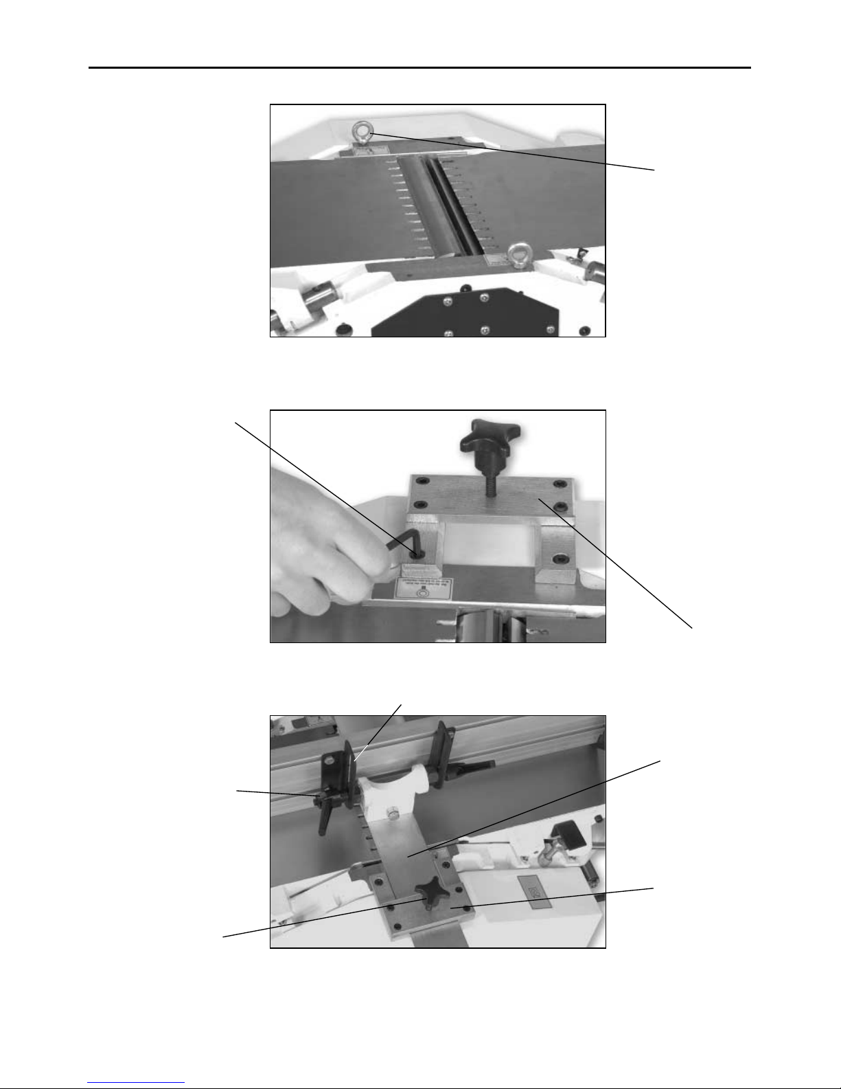
‘eye’ bolts. These screw into the top part of the
machine casting (as shown in fig 1.) and can be used
to hoist the machine clear of the pallet. If you do not
have the availability of such a hoist, and are going to
have to ‘manhandle’ the machine off the pallet; make
sure the tables are locked down before applying any
lifting force to them.
IT IS NOT RECOMMENDED THAT LIFTING, PULLING
OR PUSHING IS CARRIED OUT AGAINST THE
TABLES.
However, if expediency dictates that this is the only
method to dismount the machine, this is what must
be done. Do Not under normal circumstances lift, push
or pull the machine using the tables. Any movement is
best carried out against the main frame cabinet.
The machine should be positioned on a flat level
surface. Final levelling can be accomplished using the
levelling bolts in the base fillets of the legs. Once the
machine is in position, and level, it can be bolted to
the floor if so required.
Before adding the fence and the guarding (i.e. with the
machine ‘clean’) it is a good idea to remove the
protective grease film that is coating all the unpainted
parts of the machine. Use a proprietary de-greasing
agent or paraffin et al. Unfortunately, this cleaning
process is always a bit ‘mucky’, you are advised to wear
overalls or coveralls etc., during the process. After
cleaning, especially if you used paraffin, lightly coat
the exposed metal surfaces to prevent any rusting.
Bear in mind the stuff you will be machining and its
possible finishing process, when you choose your
anti-corrosion agent. Locate the planer fence, the
planer fence base, the two handled clamp nuts and
washers. Bolt the ‘T’ yoke to the planer fence base.
Span the bosses of the ‘T’ yoke with the two elongated
slotted lugs of the fence which are loosely bolted into
the fence. Fasten the fence to the yoke using the
handled clamp nuts and washers, position the fence as
required and fasten the four bolts that secure the
mounting lugs.
Your AW106PT2, AW128PT and AW168PT offers the
facility of your being able to plane right or left
handed. Decide on the best and most comfortable
position for you. Locate the fence mounting bracket
and fix to the machine casting as shown in fig 2, using
2 No. M6 x 12mm caphead bolts; depending on your
preferred handing. Introduce the planer fence base
into the bracket; so that the planer fence base slides
into the fence mounting bracket; then secure;
positioning the fence approximately mid-table (see fig
3). Mount the overhand plane guard arm onto the side
of the outfeed table that corresponds to your
preferred handing,then fit the overhand cutter block
guard. In the accessories packet there is a small spring
metal plate - this fits into the overhand guard
clamping assembly to spread the load of the guard
clamp onto the guard. It also prevents the bolt scoring
the upper surface of the guard,fasten in position using
the guard lock (see fig 4).
Page 7
07
Initial Assembly and Setting Up
Fence mounting
bracket
Fence mounting
bracket
Typ.2 M6 x 12mm
caphead bolt
Planer fence base
Fence securing
clamp
Typ. 2 handled
clamp nuts
Typ. 2 elongated fence
support brackets
Typ.2 small eye
bolts
Fig 3
Fig 2
Fig 1
NOTE: The pictures in this manual show the AW106PT2, the
AW128PT & AW168PT is exactly the same but on a larger scale.
Page 8
08
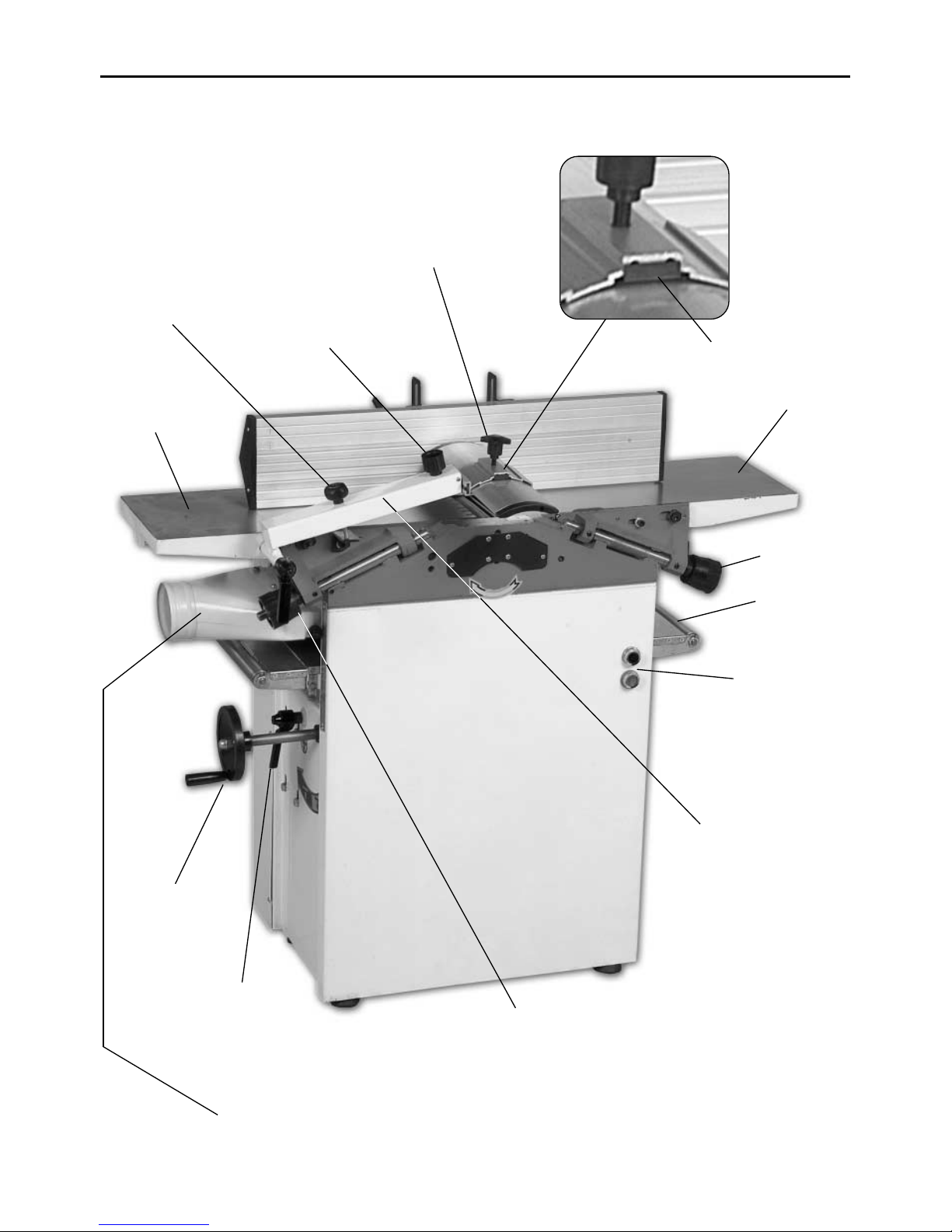
Machine Illustration and Parts Description
Start/Stop
switches
Thicknessing
table rise and fall
control
Tab le
extension
Infeed table
Infeed table
adjustor
Outfeed table
Dust extraction
hood
Overhand cutter
guard mounting
arm
Thicknessing
table rise and fall
clamping handle
Cutter block
guard clamp
Cutter block
guard angle
adjustor
Mounting arm
height adjustor
knob
Spring metal plate
Outfeed table
adjustor
Fig 4
Page 9
09
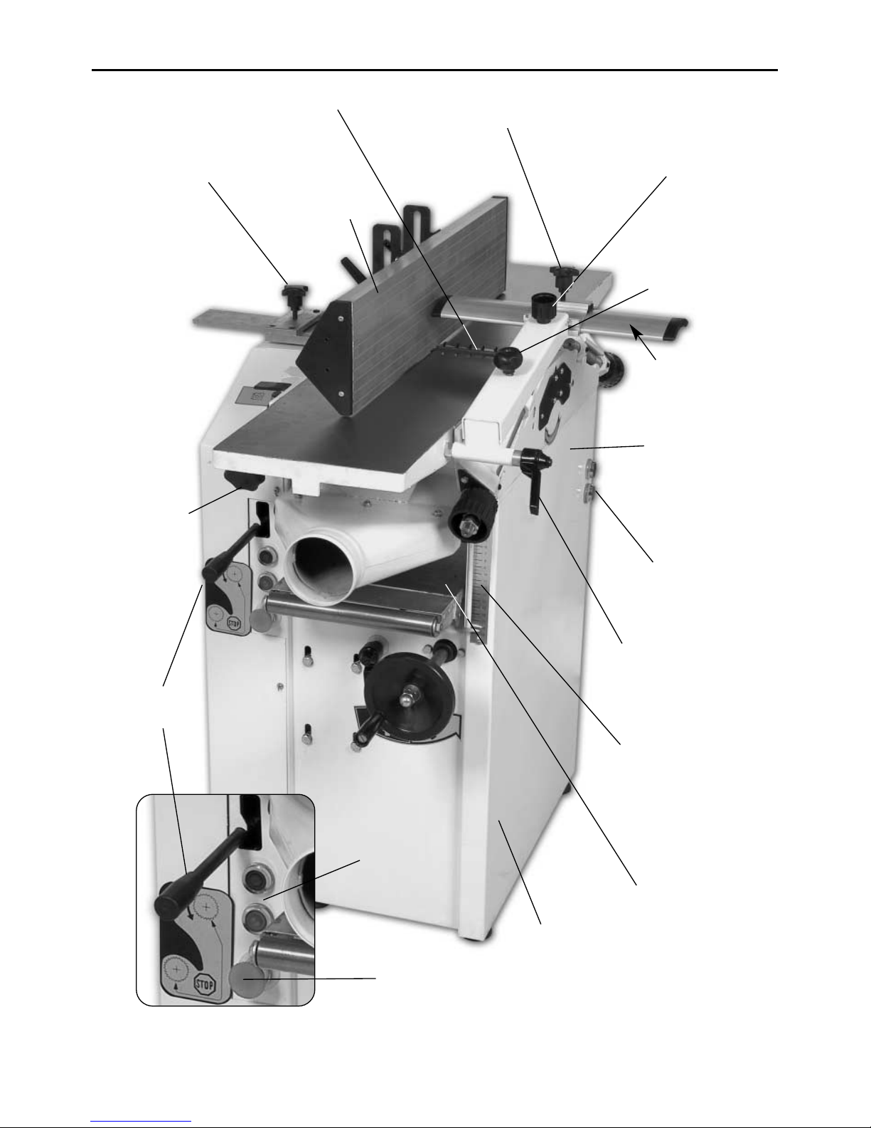
Machine Illustration and Parts Description
Main chassis
Start/Stop
switches
Start/Stop
switches
Emergency
stop
Autofeed
engage control
Thicknessing
table
Thicknessing rise
and fall scale
Outfeed table
lock
Cutter block
Cutter block guard
mounting arm lock
handle
Cutter block
guard
Cutter block
guard clamp
Cutter block
guard angle
adjustor
Mounting arm
height adjustor
knob
Fence securing
clamp
Fig 5
Fence assembly
Main chassis
Page 10
10
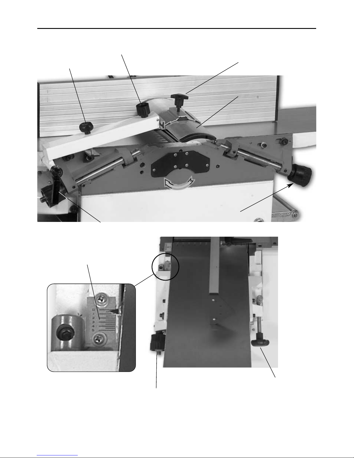
Machine Illustration and Parts Description
Infeed scale for
overhand
Cutter block
guard clamp
mounting arm
lock handle
Cutter block
guard
Cutter block
guard angle
adjustor
Mounting arm
height adjustor
knob
Infeed table lock
Infeed table
adjustor
Infeed table
adjustor
Fig 6
Fig 7a
Fig 7
Page 11
11
Machine Illustration and Parts Description
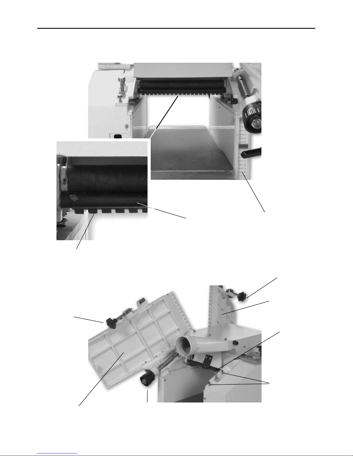
Anti-kick back
fingers
Rise and fall
scale
Outfeed table
lock
Infeed table
lock
Outfeed table
Infeed table
Table position
studs
Outfeed
Thicknessing
adjustor
Limiting bar for
material removal
Table lock stud
Fig 8
Fig 9
Page 12
12
Operating Illustrations
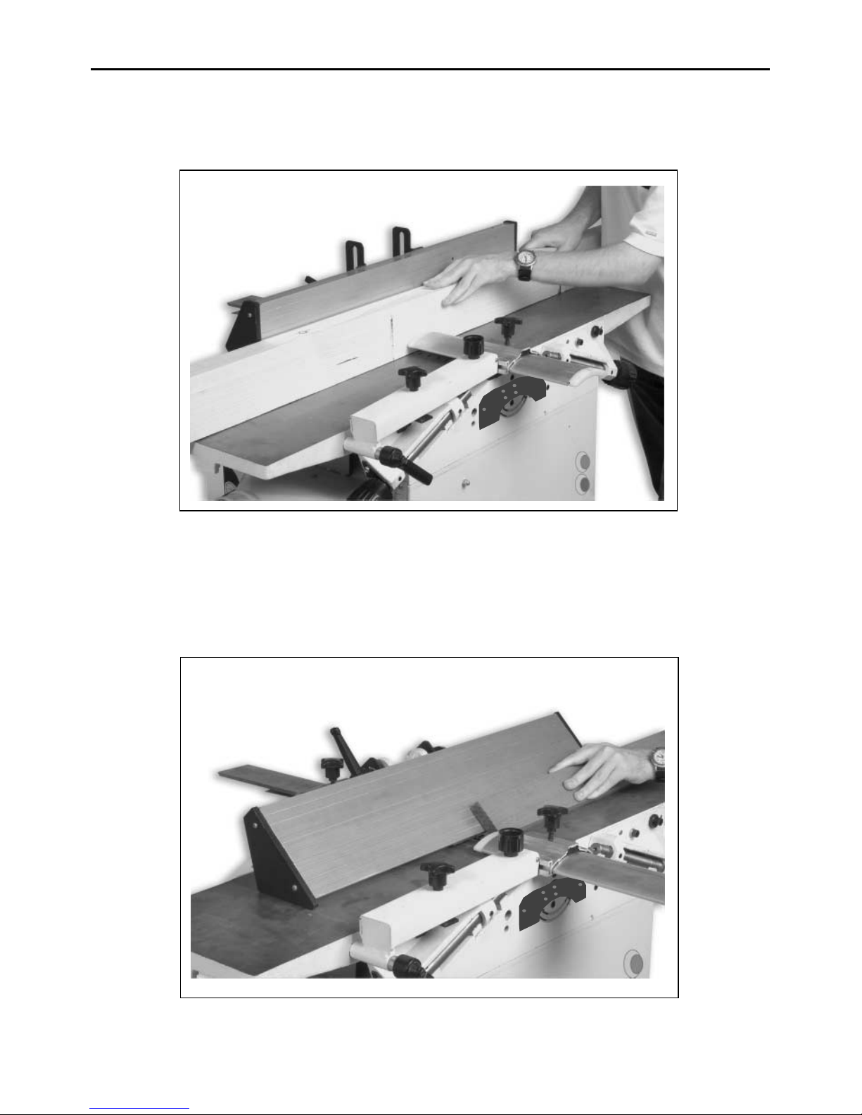
Planing with the fence inclined
Planing narrow pieces of wood
Fig 10
Fig 11
Page 13
Operating Illustrations
13
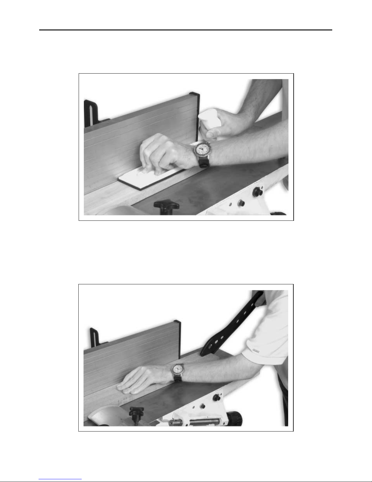
Planing short pieces of wood using a pressure pad
Planing using a push stick to carry the
timber safely over the cutter block
Fig 12
Fig 13
Page 14
14
Changing the Planer Blades
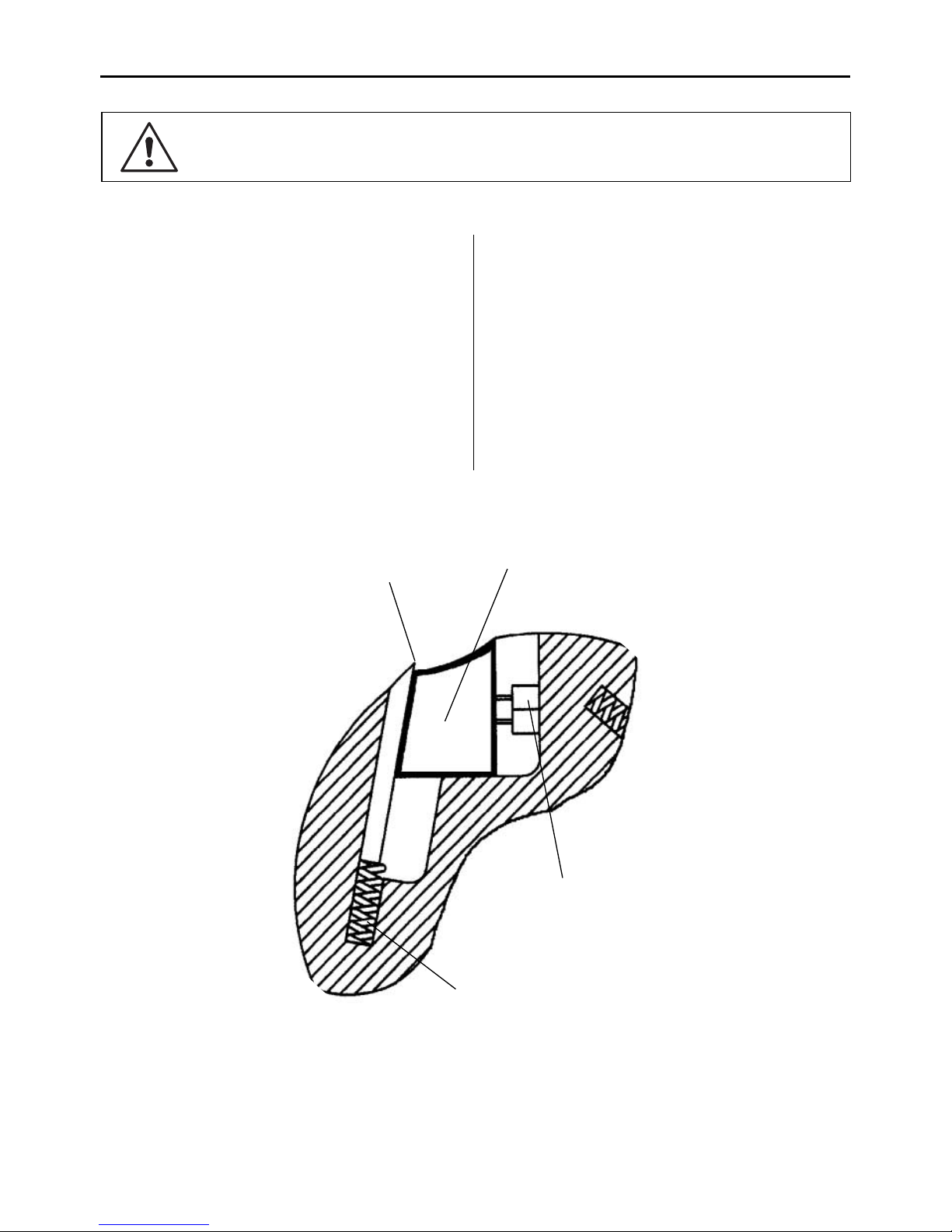
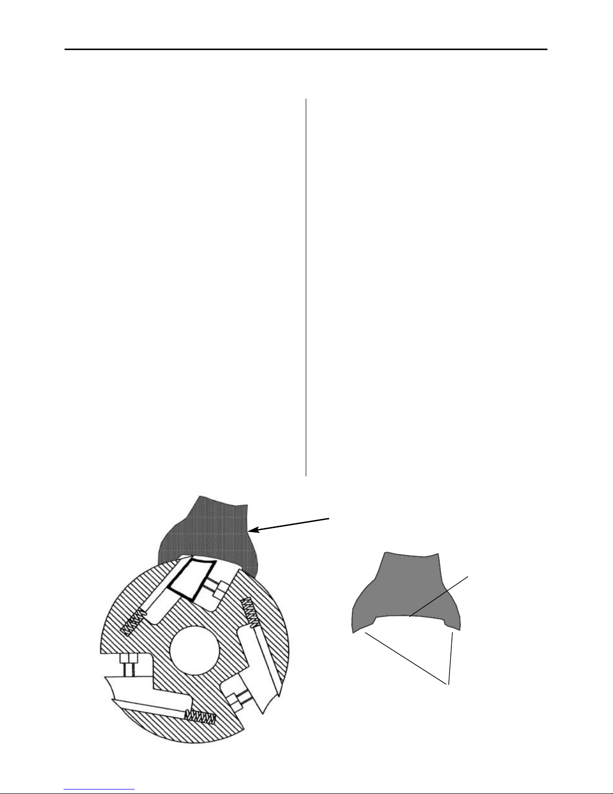
Planer knife
Chipbreaker/wedge
Clamping Bolt
Spring
Fig 14
MAKE SURE THAT THE MACHINE IS DISCONNECTED
FROM THE POWER SUPPLY!
The planer blades are mounted into 3 slot housings
machined in the cutter block.The slot housing
comprises of a slot cut on a radial axis with a reverse
tapered slot alongside it. (See fig. 14) The depth of the
first slot governs the seating of the chipbreaker/
wedge, the second slot allows the blade to be set to its
correct depth in the block.
The chipbreaker/wedge is machined with a tapered
face set at the same angle as the slot. This allows the
blade to be clamped between parallel faces. The block
will accept blades 250mm x 3mm x 30mm. After
sharpening, the blades will reduce over their height
dimension, but the blades can be safely used until
their overall height dimension is 17mm, then the
blades must be discarded as they can no longer be
securely clamped in the housing. The reverse taper
slot has a series of blind holes bored in the bottom
surface into which springs are fitted. These springs act
against the bottom of the planer blade, to push it into
contact with the setting tool, when the blades are
being positioned after changing.
Overview
Page 15
Changing the Planing Blades
15
Locate the 5.5mm x 7mm A/F spanner in the tool kit.
Turn the cutter block until one of the slots is
uppermost, (between the tables). Using the spanner
drive the 5 No. bolts into the chipbreaker/wedge, thus
removing the clamping effect. This should allow the
blade to ‘spring’ up (not like a jack in a box!) to
protrude clear of the edge of the cutter block.
Carefully remove the blade, lay aside. Remove the
chipbreaker/wedge, lay aside, finally remove the
springs from the slot and lay them aside. Repeat the
process for the other two blades. If the block becomes
difficult to hold located, being out of balance with the
blade/s removed; use a thin wedge of material to jam
the cutter block in position.
Now is a very good time to clean the slot housings
thoroughly, remove the resin build-up, sawdust, chips
and any old joiners/carpenters etc., that have recently
disappeared without trace. Ensure the circumference
of the cutter block is likewise cleaned thoroughly.
Remove the clamping bolts from the chipbreaker/
wedges, clean the bolts and the threaded holes, clean
the springs and the chipbreaker/wedges thoroughly.
Apply a little light oil to the springs. Remove the
new/sharpened blades from their ‘keeper’; set carefully
to hand and put the ‘old’ blades away in the ‘keeper’ to
be sent for sharpening. Locate the blade setting tool
and put it to hand. Screw the bolts into the
chipbreaker/wedges. Select one of the slot housings
Changing the Blades
and wedge the cutter block to maintain it in position.
Set the springs into the holes in the bottom of the
slot, introduce the chipbreaker/wedge, position it
against the ‘back’ of the slot, introduce a blade in front
of it. Using the spanner start to unscrew the bolts, take
care at this time as the blade could be protruding well
above the block. Unscrew the bolts until the wedge
just starts a ‘nip’ on the blade, then screw them back in
half a turn.
At this point all the components should be loose in
the slot (not slack), carefully position the blade and
the wedge to line up with the edge of the cutter
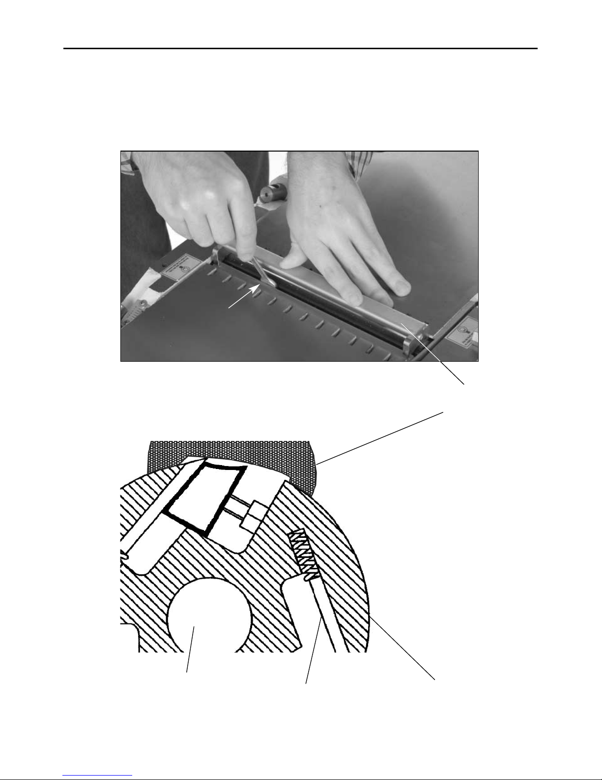
block. Press the blade setting tool gently down onto
the blade, (See fig 15 & 16) ensure that the locating
feet are firmly in contact with the cutter block, and the
blade is against the setting recess. (See fig 15 & 17)
Holding the blade and the setting tool in this position,
tighten at least two of the clamping bolts to provide a
firm clamp of the blade, with the setting tool held
firmly in place. Tighten the remaining bolts. Tighten
hard, but do not overtighten, remember, these are M4
bolts. Repeat this procedure for the remaining blades.
When all the blades are fitted, carry out a quick check
of the set of the blades, by hand rotating the cutter
block in reverse and visually inspecting the edge of
the blades against a fixed point . If this appears
satisfactory, carry out a final ‘tightness’ check on the
clamping bolts; remove all the tools and stow away.
Blade Setting Tool
Locating feet set on
cutting block
Blade setting
recess
Fig 15
Page 16
16
Changing the Planing Blades
Blade setting tool
5.5mm x 7mm
A/F spanner
Cutter block
Locating feet on the
cutting block
The blade
Fig 16
Fig 17
Page 17

17
Routine Maintenance
DISCONNECT THE PLANER THICKNESSER
FROM THE MAINS SUPPLY.
Your AW106PT2, AW128PT, AW168PT requires minimum maintenance, but it is essential that it is carried
out to ensure the longevity and correct function of the machine.
Daily
Check the overhand tables and the thicknessing bed
are clean, not coated with resin etc. Apply a
proprietary cleaner/lubricating agent.
Check the cable and the plug for damage or defects.
Mount the planer fence and check it is set upright.
Check the dust extraction hood and ensure there are
no excessive build ups of sawdust/resin, especially in
the mouth of the chip deflector and around the
mouth of the extractor.
Check the blades for sharpness and damage.
Check the rollers of the thicknessing table rotate
freely, and there is no build up between the roller
and the extension plate.
Weekly
Carry out the above checks.
Clean the machine thoroughly, remove any shavings,
sawdust, chips etc, from in, under and around the
machine.
Check the cutter block for resin build up, especially
behind the blade and in the scallop of the
chipbreaker/wedge.
Raise the tables and brush out and clean any debris or
build up around the area of the noise attenuating slots
in the edges of the overhand tables.
Check the infeed and take off pressure rollers are not
clogged, clean as necessary.
Check the action of the anti-kickback fingers, again
clean and lubricate as required.
Monthly
Carry out the above checks. After cleaning apply a
little light oil to the bearing ends of the infeed, take off
and extension table rollers. (Refer to Fig 18,19)
Remove the rear machine cover plate, check the
condition and tension of the drive belt.
Check the autofeed engage and disengage function.
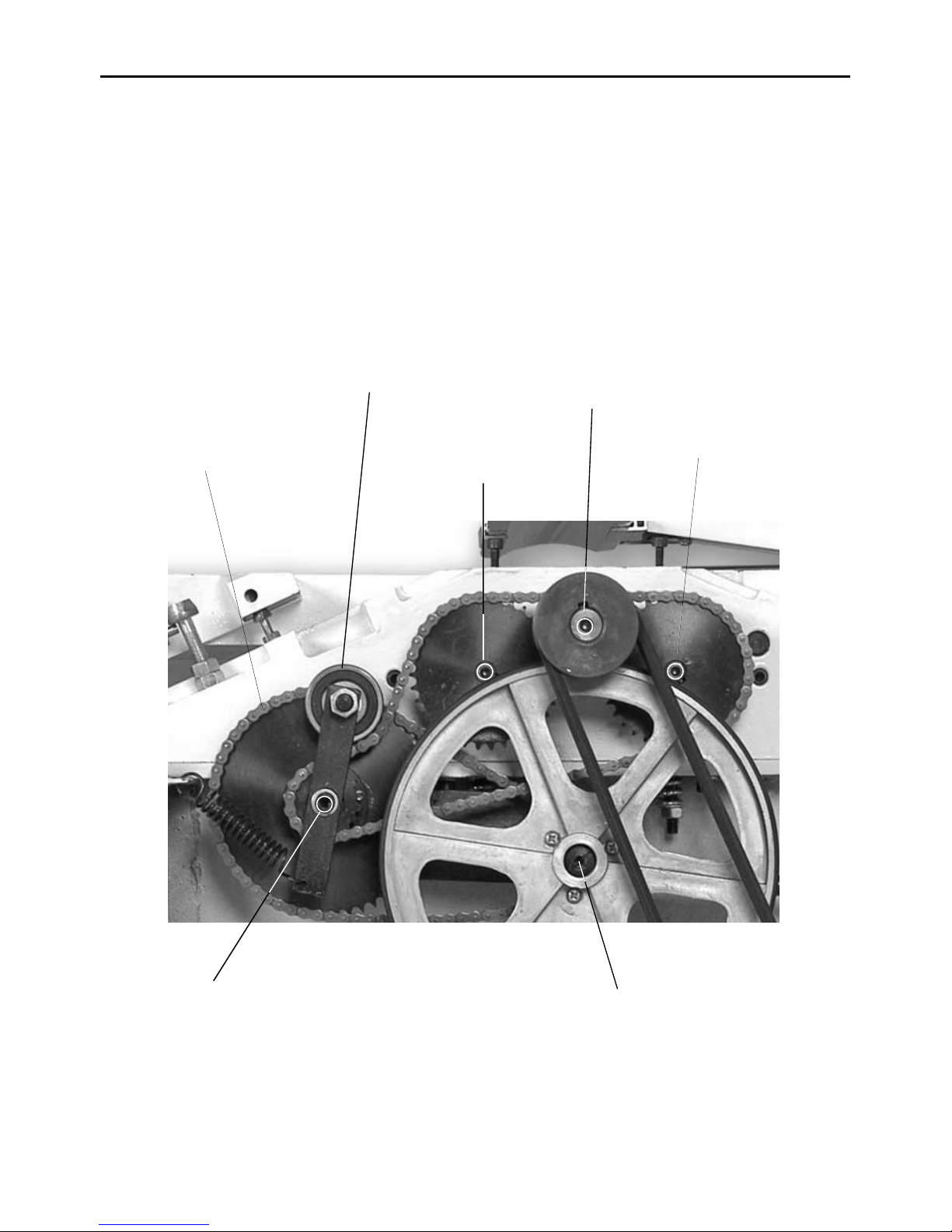
Check the condition of the drive chains, clean and
apply a light coating of oil to the chains and sprockets.
Apply a light oiling to all the bearing areas, taking care
not to get oil on the tyre surfaces. Replace the rear
machine cover plate.
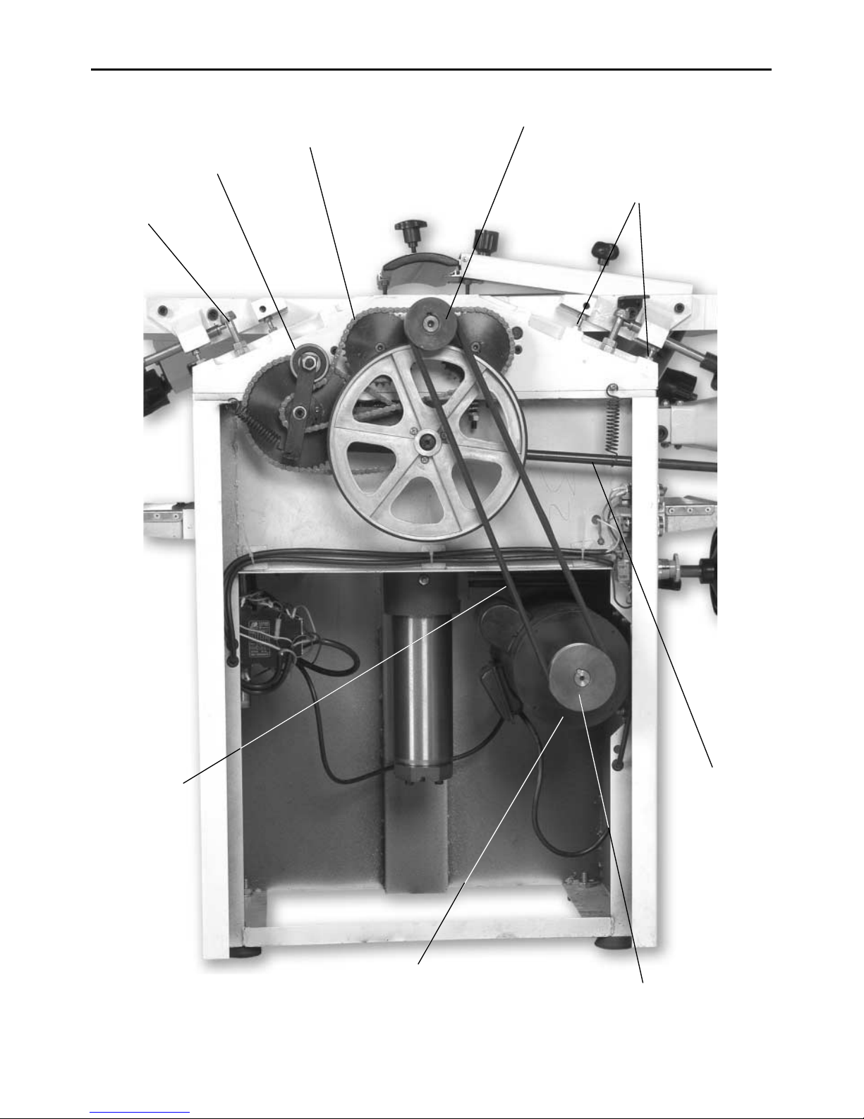
Re-tightening table lock downs. (Refer to Fig 18)
If the table lock downs becomes ‘slack’ they can be
adjusted by altering the height of the table lock stud.
Hold the stud firmly and loosen the lock nut, adjust
the stud, lightly ‘pinch’ with the lock nut, try.
If correct, fully tighten the lock nut, if not, repeat the
process until the ‘lock down’ is correct.
Page 18
18
Routine Maintenance
Fig 18
Autofeed engage
and---- disengage
control
Drive chain
Bearing
Motor
Drive belt
Table position
studs
Table lock stud
Drive belt pulley
Motor pulley
Page 19
19
Routine Maintenance
Oil
Oil
Oil
Light coat of oil on
the chain
Oil
Oil
Light coat of oil
on bearing
OIL POINTS
Fig 19
Page 20
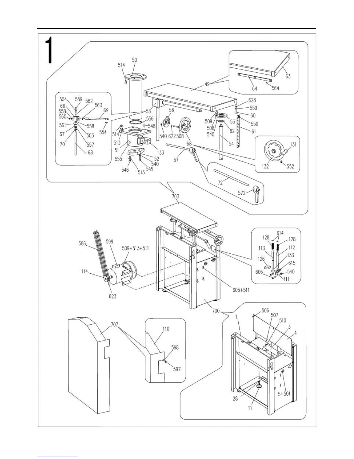
20
Parts List/Drawing 1 (AW106PT2)
Page 21
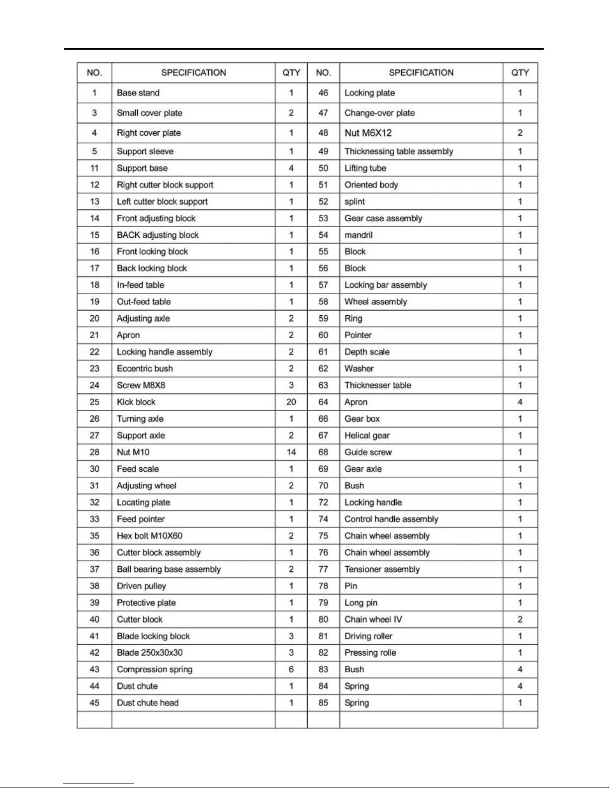
21
Parts List/Drawing 1 (AW106PT2)
Page 22
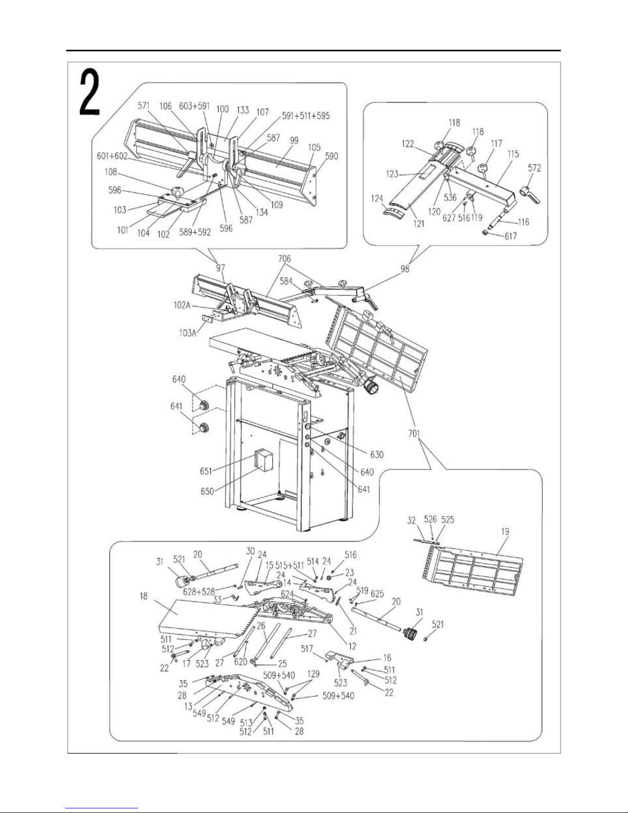
22
Parts List/Drawing 2 (AW106PT2)
Page 23
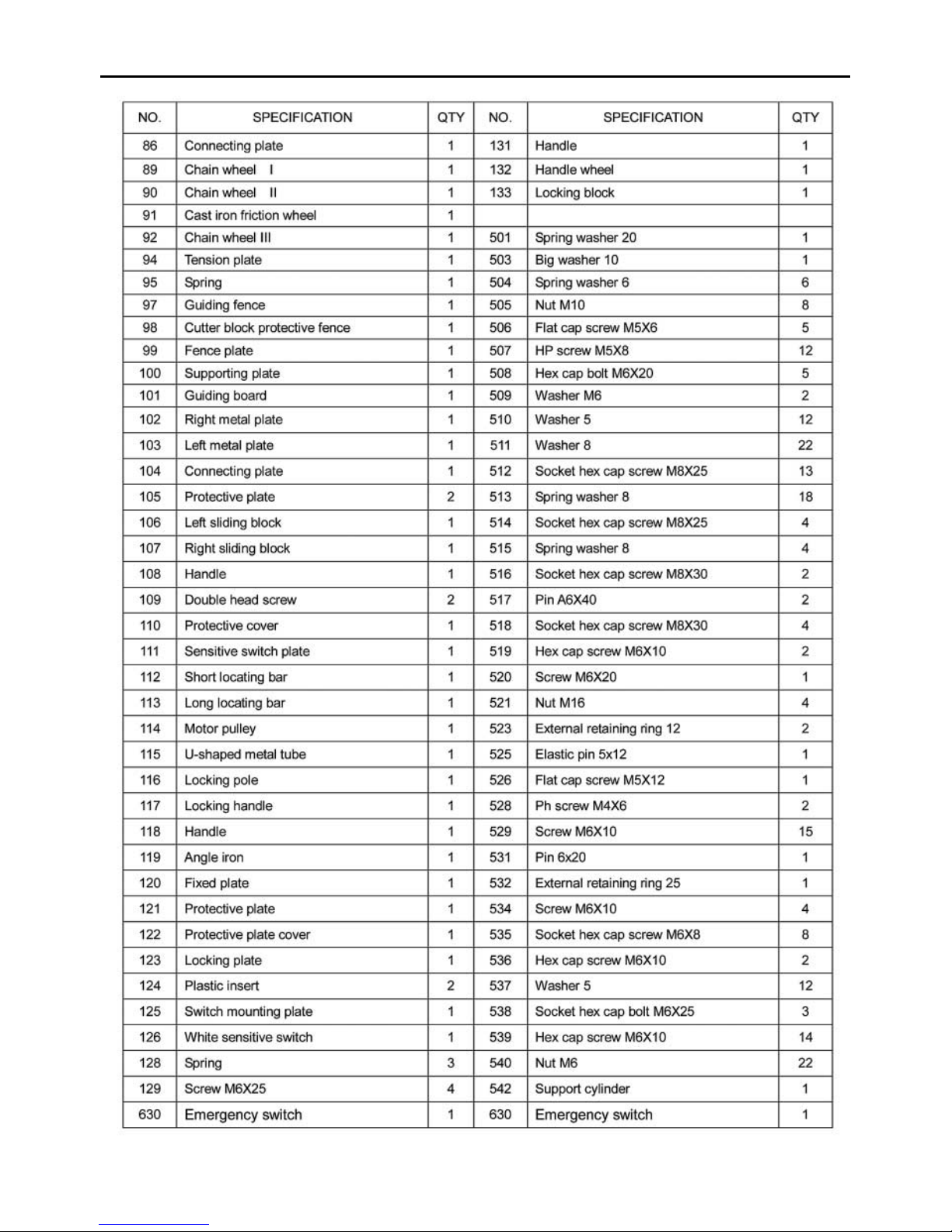
23
Parts List/Drawing 2 (AW106PT2)
Page 24
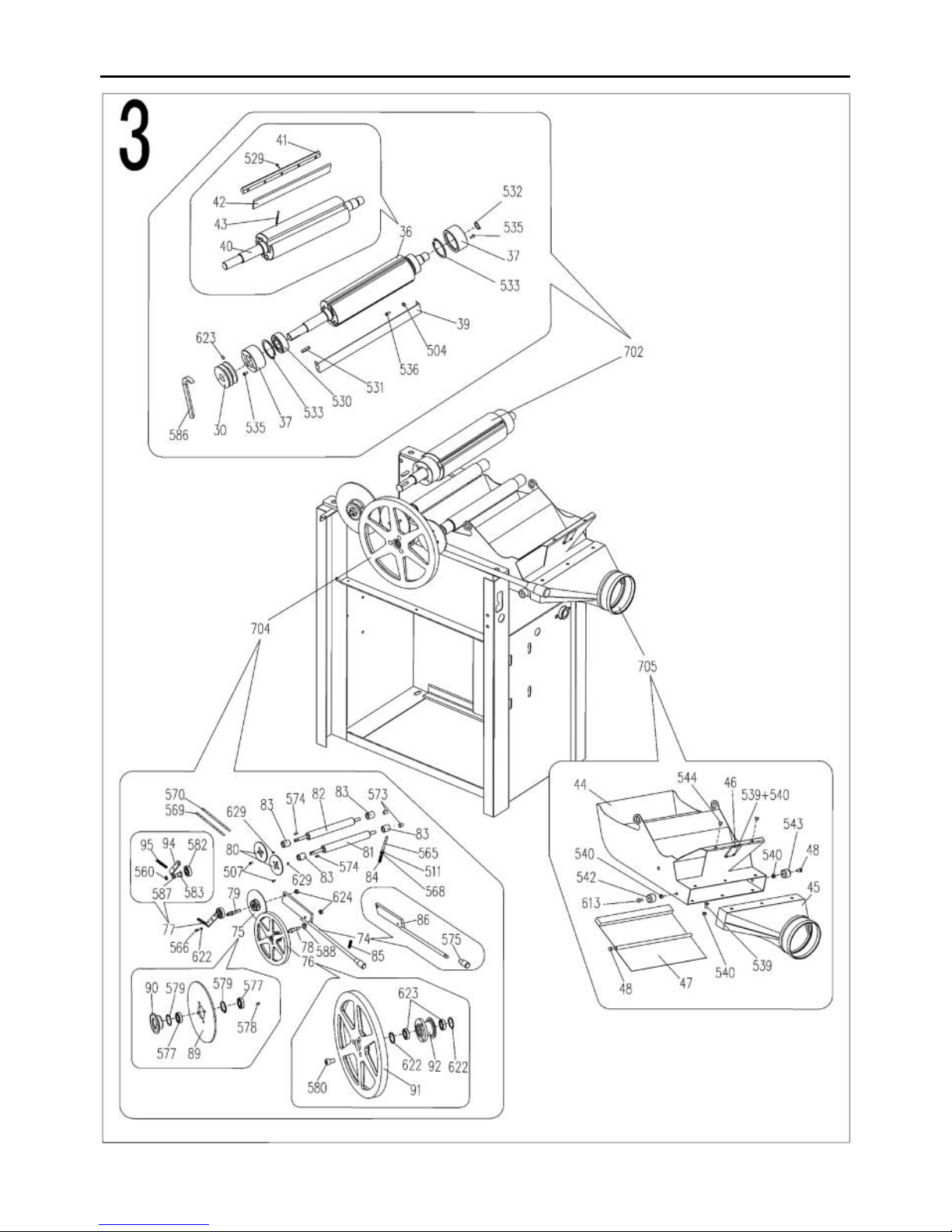
24
Parts List/Drawing 3 (AW106PT2)
Page 25
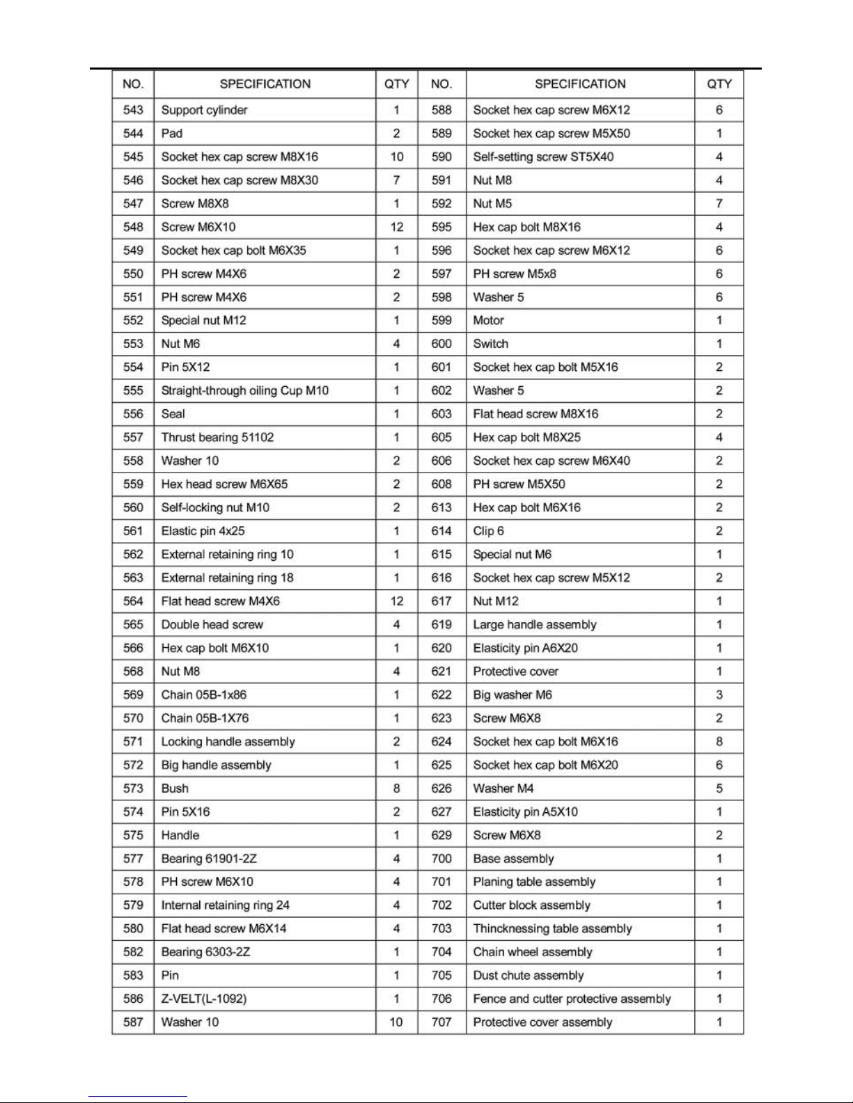
25
Parts List/Drawing 3 (AW106PT2)
Page 26
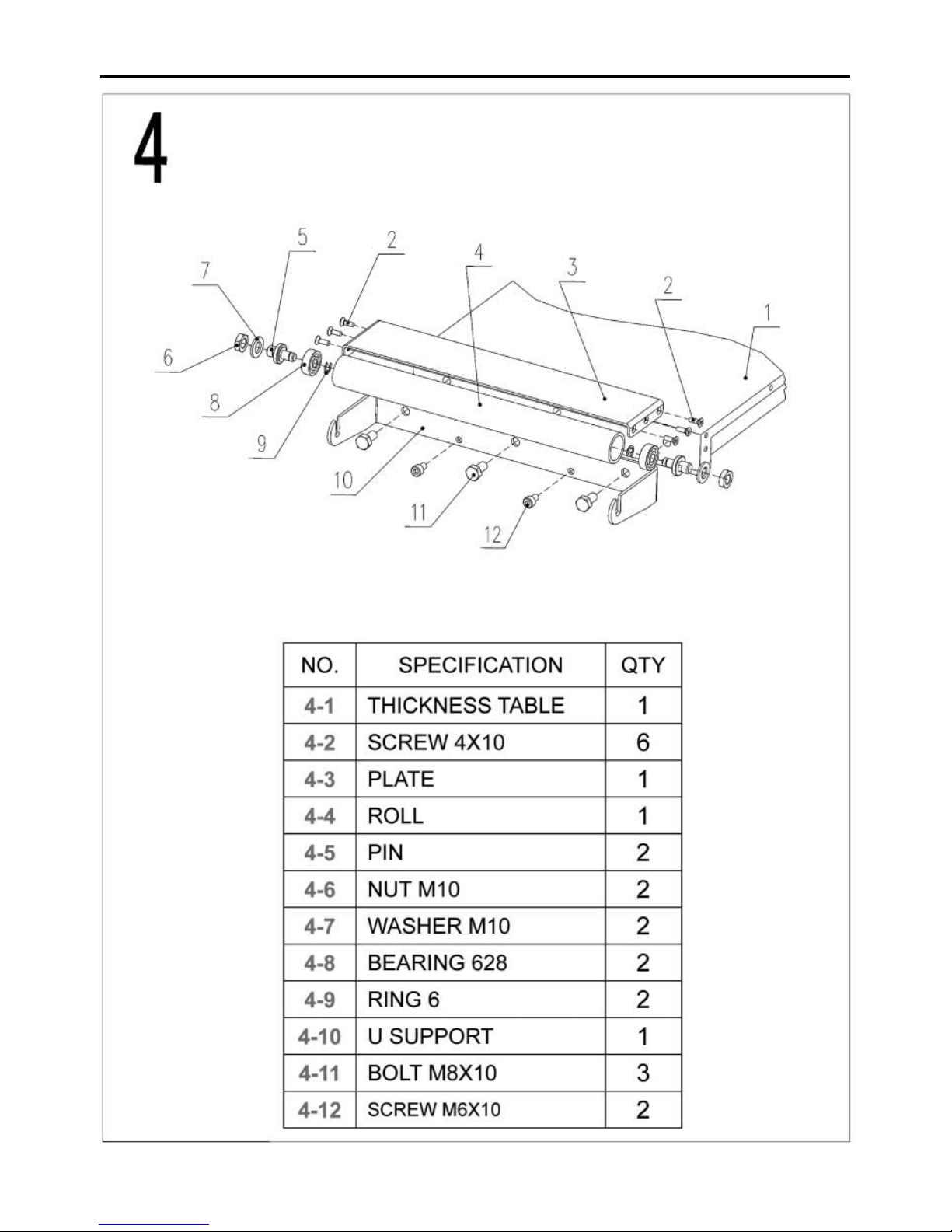
26
Parts List/Drawing 4 (AW106PT2)
Page 27
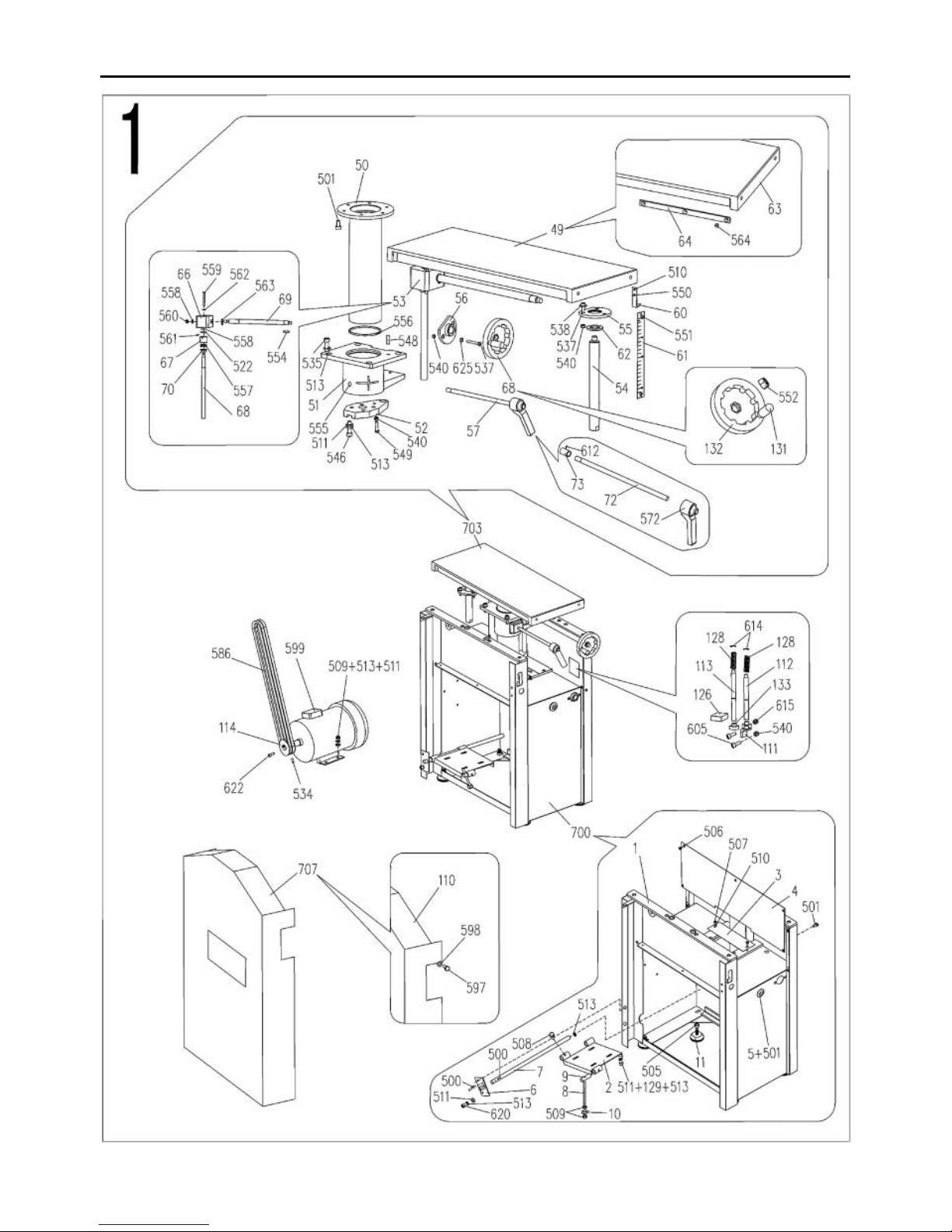
27
Parts List/Drawing 1 (AW128PT-AW168PT)
Page 28
28
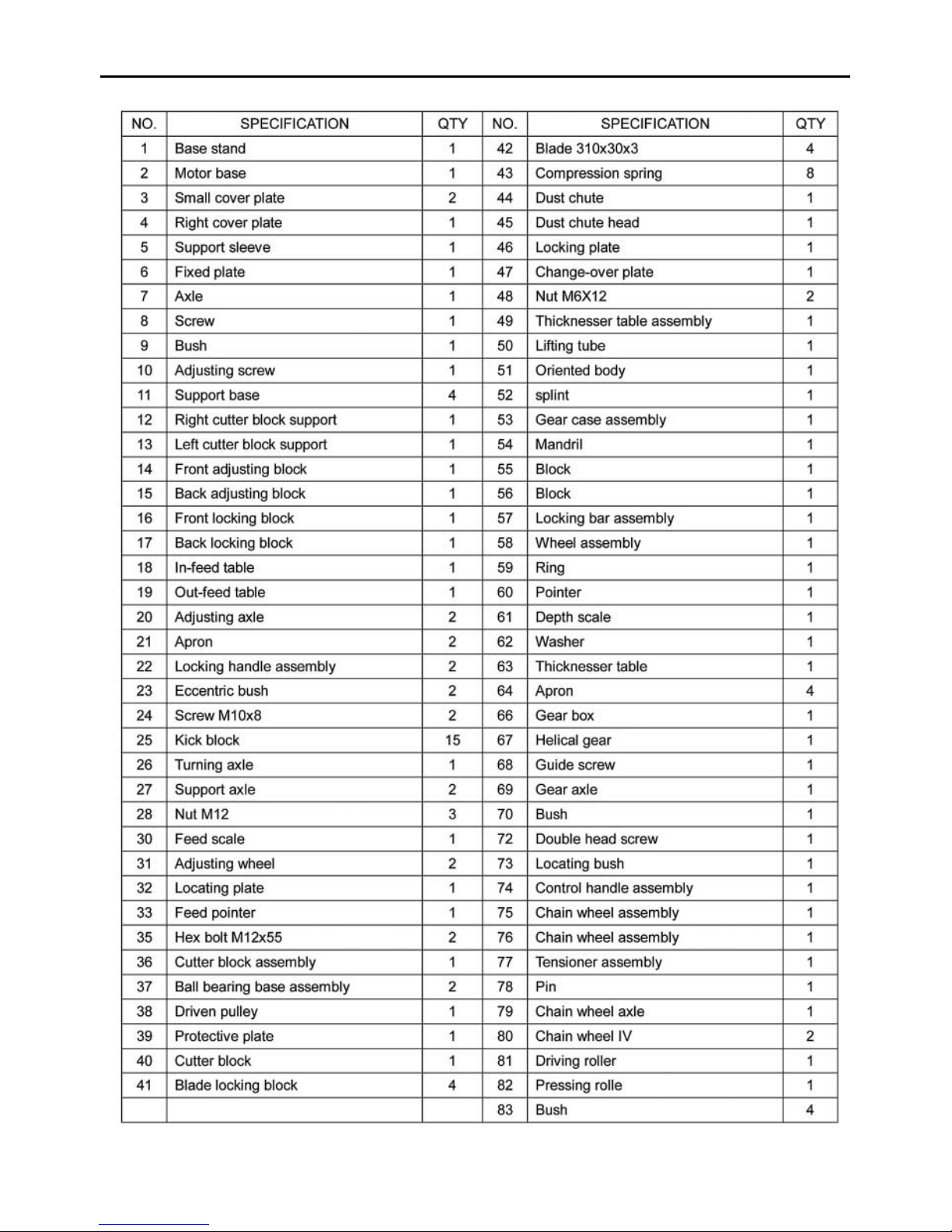
Parts List/Drawing 1 (AW128PT-AW168PT)
Page 29
29
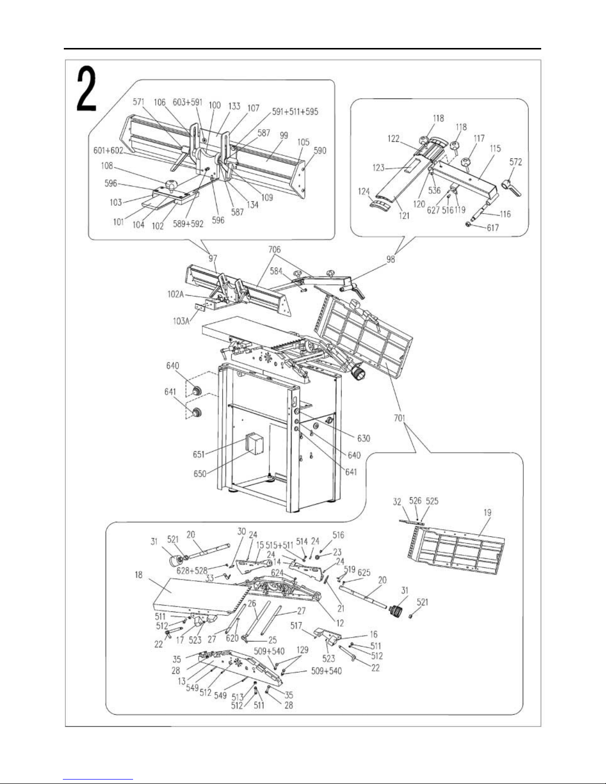
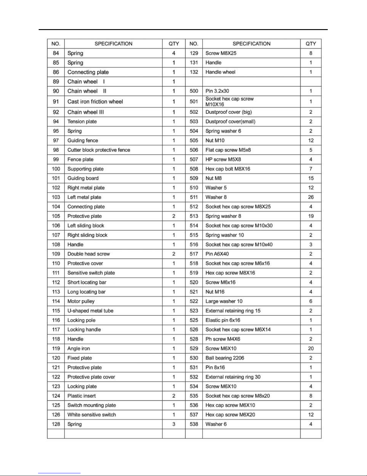
Parts List/Drawing 2 (AW128PT-AW168PT)
Page 30
30
Parts List/Drawing 2 (AW128PT-AW168PT)
Page 31
31
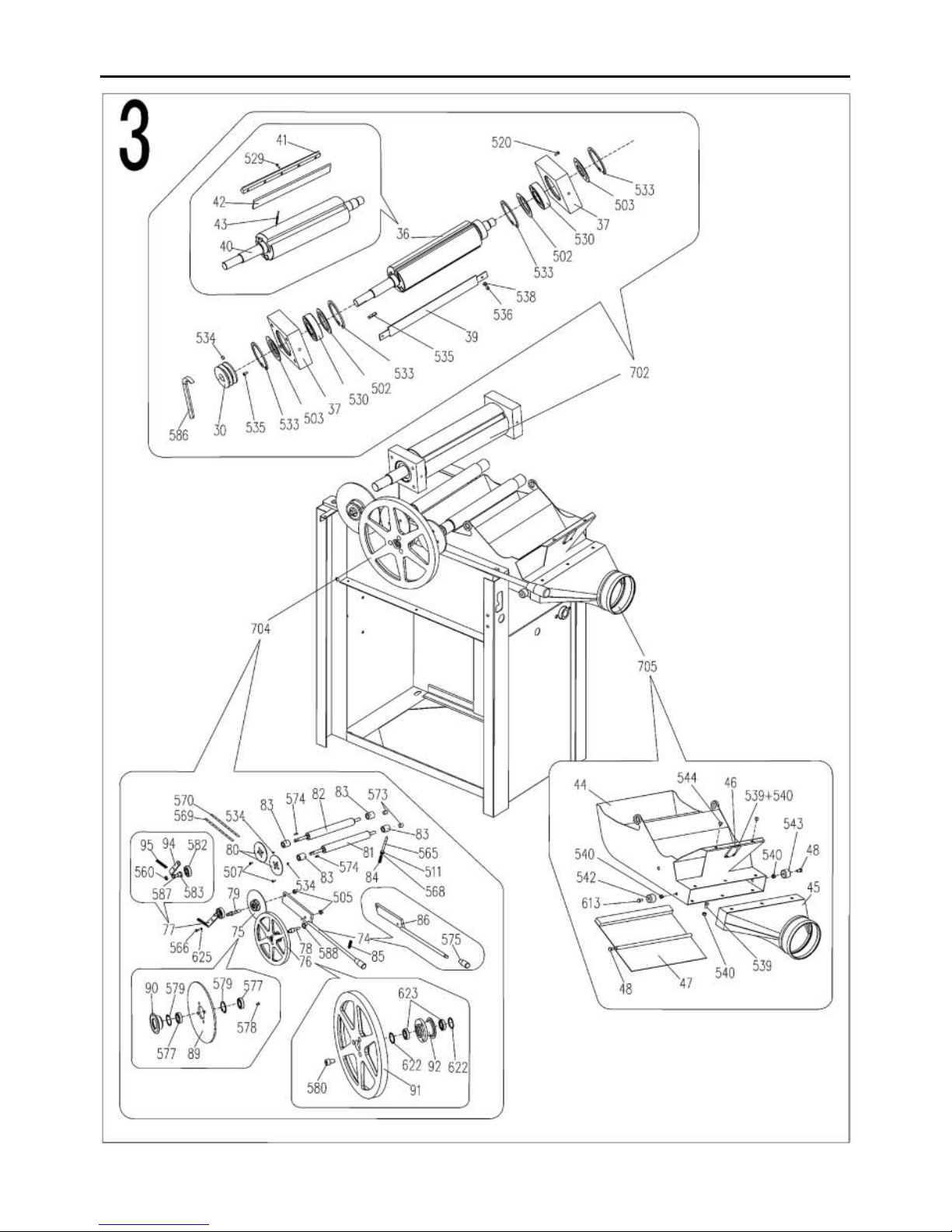
Parts List/Drawing 3 (AW128PT-AW168PT)
Page 32
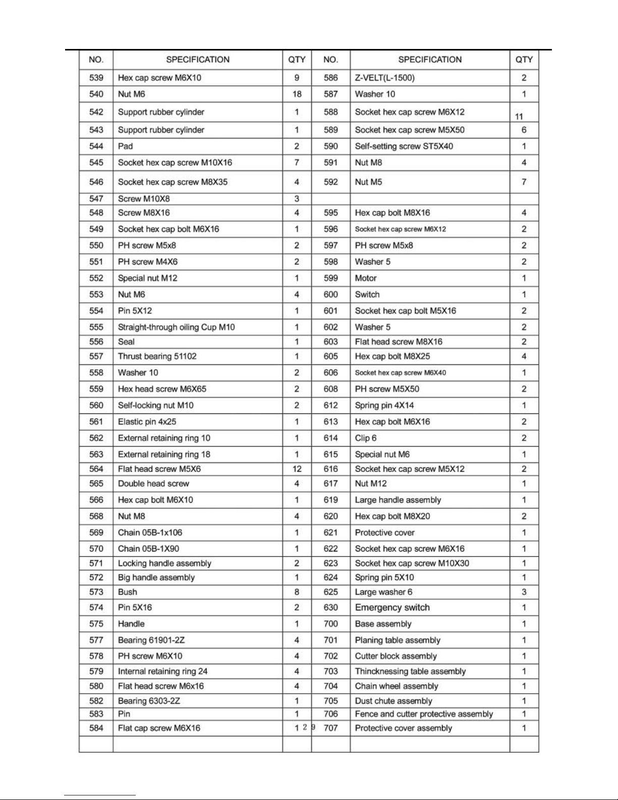
32
Parts List/Drawing 3 (AW128PT-AW168PT)
Page 33
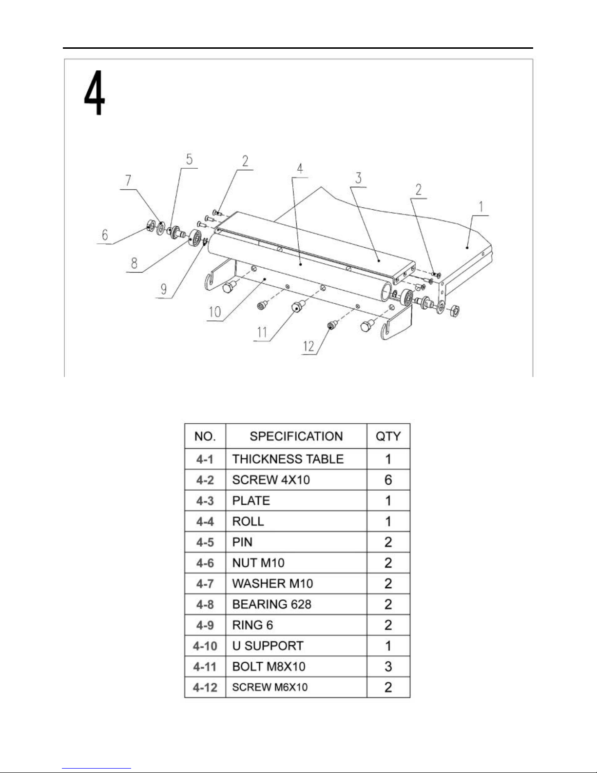
33
Parts List/Drawing 4 (AW128PT-AW168PT)
Page 34

34
Notes
Page 35

35
Notes
Page 36

Please dispose of packaging for the product in a responsible manner. It is suitable for recycling.
Help to protect the environment, take the packaging to the local recycling centre and place into the
appropriate recycling bin.
Do not dispose of electric tools together with household waste material. In observance of
European Directive 2002/96/EC on waste electrical and electronic equipment and its
implementation in accordance with national law, electric tools that have reached the end of
their life must be collected separately and returned to an environmentally compatible recycling
facility.
Only for EU countries
 Loading...