


AT508WL
Woodturning Lathe
Code 102265
Original Instructions
AT&M: 04/07/2019
BOOK REF : 103273

Index of Contents
EU Declaration of Conformity 02
What’s Included 03-04
General Instructions for 230V Machines 05
Specific Safety Instructions for Woodturning Lathes 06
Specification 06
Assembly 08-09-10-11
Illustration and Parts Description 12-13-14-15
Operating Instructions
Rotating the Headstock 1
Removing the Faceplate 17
Live Centre Nose Cone 17
Indexing Facility 18
Removing the Drive Centre 19
Changing the Belt Speed 19
Alignment Centre 20
Digital Display 1.5V SR44 Battery 20
Maintenance 21
Exploded Diagram/Parts List 22-23-24-25-26-27
Wiring Diagram 28
CE Certificate 29-30
Notes 31
EU Declaration of Conformity
Cert No: KC-INV
Axminster Tools & Machinery Ltd
Axminster Devon
EX13 5PH UK
axminster.co.uk
declares that the machinery described:-
Type Woodturning Lathe
Model AT508WL
Signed
Andrew Parkhouse
Operations Director
Da te: 5/12/2014
The symbols below advise the correct safety procedures when using this machine.
EU Declaration of Conformity
This machine complies with the following directives:
2006/42/EC
2004/108/EC
EN 61000-6-2:2005
EN 61000-6-4: 2007+A1:2011
and conforms to the machinery example for which the
EC Type-Examination Certificate No RA/2014/80020C, RD/2014/C0010C
has been issued by KINGCRAFT MACHINERY COMPANY LIMITED.
at: No. 26, Gong Yeh 12rd., Dah Li District, Taichung City, Taiwan
and complies with the relevant essential health and safety requirements.
EN ISO 1200: 2010
EN 60204-1: 2006+AC:2010
Fully read manual
and safety instructions
before use
Ear protection
should be worn
Eye protection
should be worn
2
Dust mask
should be worn
HAZARD

What’s Included
Quantity Item Part Model Number
1 Variable Speed Wood Lathe A AT508WL
1 Tool Rest Extension Post B
1 Spanner C
1 Live Centre Push Rod D
1 Push Rod E
1 Tool Rest (Small) F
1 Tailstock Live Centre G
1 Alignment Centre 2MT H
1 4 Prong Drive Centre 2MT I
1 Face Plate J
1 Tool Rest (Large) K
4 Adjustable Feet L
2 Lathe Stands M
1 Lathe Extension Bed N
1 Motor Handle O
1 Spindle Locking Pin (with Magnetic Base) P
Fixing Q
A
3
Continues Over....

What’s Included
P
O
K
F
E
C
B
D
G
H
J
I
Q
M
N
4
L

General Instructions for 230V Machines
The following will enable you to observe good working
practices, keep yourself and fellow workers safe and maintain
your tools and equipment in good working order.
WARNING!! KEEP TOOLS AND EQUIPMENT
OUT OF REACH OF YOUNG CHILDREN
KEEP WORK AREA AS UNCLUTTERED AS IS
PRACTICAL. UNDER NO CIRCUMSTANCES
SHOULD CHILDREN BE ALLOWED IN WORK
AREAS.
Mains Powered Tools
• Tools are supplied with an attached 13 Amp plug.
• Inspect the cable and plug to ensuree that neither are
damaged. Repair if necessary by a suitably qualified person.
• Do not use when or where it is liable to get wet.
Workplace
• Do not use 230V a.c. powered tools anywhere
within a site area that is flooded.
• Keep machine clean.
• Leave machine unplugged until work is about to commence.
• Always disconnect by pulling on the plug body and not the
cable.
• Carry out a final check e.g. check the cutting tool
is securely tightened in the machine and the correct
speed and function set.
• Ensure you are comfortable before you start work,
balanced, not reaching etc.
• Wear appropriate safety clothing, goggles, gloves,
masks etc. Wear ear defenders at all times.
• If you have long hair wear a hair net or helmet to prevent it
being caught up in the rotating parts of the machine.
• Consideration should be given to the removal of rings and
wristwatches.
• Consideration should also be given to non-slip footwear etc.
• If another person is to use the machine, ensure they are
suitably qualified to use it.
• Do not use the machine if you are tired or distracted
• Do not use this machine within the designated safety areas
of flammable liquid stores or in areas where there may be
volatile gases.
• Check cutters are correct type and size, are undamaged
and are kept clean and sharp, this will maintain their
operating performance and lessen the loading on the
machine.
• OBSERVE…. make sure you know what is happening
around you and USE YOUR COMMON SENSE.
5

Specific Safety Instructions for Wood turning Lathes
1. Do not use ‘split’ work pieces.
2. Always start at the lowest speed when starting a new task.
3. Check that the tool rest is at or slightly below the centre line
of the work piece.
4. Check the work piece is securely mounted in the lathe before
switching on the power.
5. Rotate the work piece by hand, to check that it is centralised,
clear of the tool rest, not ‘split’ or has loose knots.
6. Where lathes have the facility to be reversed; check the
machine is rotating in the correct
direction.
7. If your lathe has the facility to run in reverse, you must ensure
Specification
that the mounting accessories (chucks, faceplates etc.,) can
be ‘locked’ onto the lathe mandrel, and in the case of chucks,
have some form of security device to prevent them ‘unwinding’
during reverse operation.
8. Make sure your tools are stored/racked away from the
turning area of the lathe. Do not reach over a rotating work
piece at any time.
9. Do not ‘dig in’ or try to take too large a cut.
10. Do not leave the lathe running unattended; or leave the
machine until everything is stopped.
11. Some turning tools may have specific sharpening angles
that have been determined by the manufacturers; when
re-sharpening, adhere to these angles to maximise the finish
of your work.
Code 102265
Model AT508WL
Rating Trade
Power 2.2kW 230V 1ph
Speed 60-1,200, 100-2,200, 140-3,700 rpm
Spindle Taper MT2
Spindle Thread M33 x 3.5mm
Taper Tailstock MT2
Distance Between Centres 762mm + 500mm with extension bed (depending on the centres fitted)
Max Diameter over Bed 508mm
Tool Rest Stem Diameter 30mm
Overall L x W x H 1,800 (plus 500mm with Bed Extension) x 600 (plus 330mm with Side Extension) x 1,230mm
Weight 280kg
6

Assembly
Important Notes
Please take some time to read the section entitled ‘Illustration
and Description’ to identify the various parts of your machine
so that you are familiar with the terminology we will use to
enable you to set up and operate your table lathe safely and
correctly.
The lathe and its accessories will arrive coated with corrosion
preventative grease. This will need to be cleaned from the
lathe, its components and accessories prior to it being set up.
Wearing overalls and rubber gloves is advisable, as is eye
protection. After cleaning, lightly coat the machine with a
thin layer of light wax.
UNPACK YOUR NEW LATHE AND RECYCLE
THE PACKAGING RESPONSIBLY. THE CARDBOARD PACKAGING IS BIODEGRADABLE.
WARNING: THE WOOD LATHE IS A HEAVY
MACHINE, IT IS ADVISABLE TO USE A LIFTING
DEVICE SUCH AS A HOIST, SCISSOR LIFT OR
SEEK HELP WHEN ASSEMBLING THE LATHE.
2. Carefully remove the headstock, tailstock and tool rest banjo
and place safely aside, see fig 06-07-08.
NOTE: Before you remove the headstock assembly, first
remove the Electronic inverter control box from the pallet
by removing the two securing screws and place safely aside,
see fig 05.
3. Using a lifting device or seek help, lift the lathe bed from the
pallet onto a work bench in rediness to mount the leg stands
(M).
Control box unit
Phillips screws
Fig 05
Fig 06-07-08
WARNNING! WE RECOMMEND YOU REMOVE
THE HEADSTOCK, TOOL REST AND TAILSTOCK
FROM THE LATHE BED BEFORE LIFTING THE
LATHE ASSEMBLY OFF THE PALLET
PLEASE NOTE: The Trade Lathe comes 90%
pre-assembled. In order to reduce the footprint of the
machine for packaging, several items are dismounted from
the machine and need to be re-affixed. Please check all the
boxes, packets etc. to make sure that all the parts have
been accounted for.
1. Remove the headstock and tailstock stop pins to the ends of
the lathe bed and place safely aside, see fig 01-02.
Fig 01-02
Tailstock
Banjo
Stop Pin
7
Headstock
Continues Over....

Assembly
Stand Assembly
1. Locate the two lathe stands (M) and the four adjustable feet
(L). Screw the threaded feet into the pre-drilled holes to the
base of the stands, see fig 09.
Fig 09
M
L
2. Place the leg stands on their feet, locate the eight M10 bolts,
spring washer/washers, see fig 10. Place a washer/spring washer
over each bolt, using a lifting device or get assistance lift the
lathe bed up about 700mm from the floor. Line up the four
machined holes two each end of the lathe bed with the holes
in the leg stands (M) and secure in place with the four M10
bolts. Using a 17mm socket or spanner securely tighten, see figs
11-12-13.
Fig 10
M10 Bolt
Fig 11-12-13
700mm
3. Before replacing the headstock banjo/tool rest and
tailstock to the lathe bed, remove the oil residue from all
machined surfaces, see fig 14-15.
Fig 14-15
8

4. Make sure the lathe bed is thoroughly cleaned then replace
the headstock banjo/tool rest and tailstock, replace the stop
pinsto either end of the lathe bed, see fig 16-17-18-19.
Fig 16-17-18-19
Assembly
Hex screw
Hex key
Electronic Inverter Control Box
Locate the inverter control box and two Hex screws. Position
the control box up inside the leg stand (M) and line up the
threaded holes in the mounting bracket with the top two holes
inside the leg stand assembly. Using a Hex key insert the two
Hex screws through the leg stand casting and into the control
box mounting bracket, see fig 20-21-22.
Fig 20-21-22
Mounting bracket
Inverter control box
Main Control Box
The main control box has a magnetic base enabling it to be
positioned anywhere on the lathe, see fig 23.
9
Continues Over....
Fig 23

Assembly
Lathe Bed Extension
The extension bed (N) will increase the capacity of your lathe in three
ways. The lathe can be used with the main bed either way around, this is
because the extension bed (N) can be mounted either on the end of the
main bed to extend the distance between centres, on the leg stand (M)
to create a bigger turning diameter, or on a mounting plate machined
onto the side of the main bed. This allows bowl turning with the
headstock rotated to suit.
Setup 1 ( to increase distance between centres)
Locate the four cap head bolts/spring/washers and the bed extension
(N). Remove the stop pin from one side of the lathe bed and place safely
aside. Place a sping/washer over each cap head bolt, with help align the
for holes in the bed extension (N) with four threaded holes to the end of
the lathe bed. Insert the bolts through the castings and just nip up the
bolts. Manoeuvre the tailstock over the two beds and lock in place. (this
aligns the two beds) Now tighten all four cap head bolt to secure the
extension in place. Replace the stop pin in the extension bed (N), see fig
24-25.
Fig 24-25
Stop pin
Height mounting plates
Fig 27-28
Cap head bolt
Threaded holes
N
Setup 2 ( mounted to leg stand)
1. The extension bed can be mounted to the leg stand (M) in
two set heights for the required piece being turned, see fig 26.
Align the holes in the extension bed with the thread holes to
one of the set height mounting plates and secure with the four
cap head bolts, see fig 27-28.
3. Loosen tool rest extension clamp and insert one of the two
tool rests (F) or (K) and secure in position.
4. Remove the tailstock assembly and place safely aside, lift up
the headstock locking handle and slide the headstock assembly
until it’s up against the edge of the lathe bed and lock in place.
Insert the stop pin in the lathe bed and extension bed, see fig
29.
Fig 29
2. Slide the banjo assembly into the extension bed. Loosen the
tool rest clamping handle, locate the tool rest extension post (B)
and insert it into the banjo and tight the clamping handle.
10

Assembly
Setup 3 ( mounted to side of the lathe bed)
The extension bed can be mounting to one side of the lathe
bed, this feature allows you to use the headstock at a set angle
for turning bowls and gives the user more flexibility.
Position the extension bed so the holes line up with the ones
on the mounting plate and secure in place as described on the
previous setups, see fig 30-31-32.
Fig 30-31-32
Mounting plate
2. Insert drive centre Morse taper (G) into the headstock
spindle and repeat the process for the live centre (I) into the
tailstock barrel. Make sure firmly home, see fig 37-38.
Fig 34
Fig 35-36-37-38
Drive Centre & Live Centre
1. Locate both live and drive centres (I and G). Locate the
spindle locking pin (P), rotate the spindle until the machined
hole on the shaft lines up with the spindle collar access hole.
Insert the locking pin to lock the spindle and undo the two
locking grub screws on either side of the boss, see fig 33. Place
the supplied spanner (C) over the boss and remove the face
plate, place safely aside, see fig 34. Clean all traces of oil and
greese from the drive/tailstock spindle barrels and live/drive
centres/morse tapers, see fig 35-36.
Fig 33
Grub screw
P
I
G
11
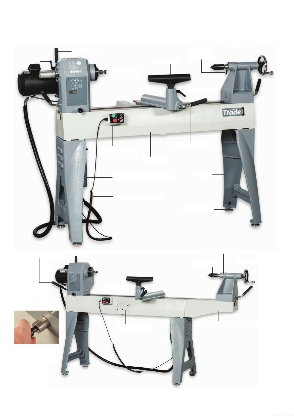
Illustration and Parts Description
Motor locking handle
Motor handle
Four prong
drive centre
Tailstock
Tailstock
barrel lock
Tool rest
Tool rest lock
Setup 1
Headstock locking handle
Control box with
magnetic base
Lathe bed
Electronic inverter control box
Flexible control box cord
Headstock
Banjo lock handle
Stand
Adjustable foot
Digital readout
Live centre
Tailstock wheel
Headstock pivot lock
Pull the pivot lock back
enabling you to rotate
the headstock
Setup 2
Mounting plate
12
Tailstock locking leverExtension bed
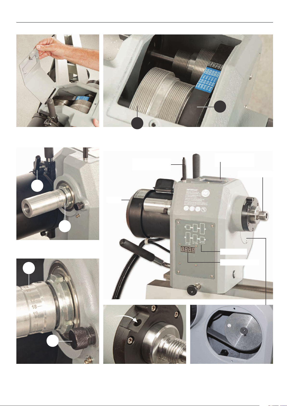
Illustration and Parts Description
B
A
Motor pulley access panel Motor and spindle pulleys (A), Drive belt (B)
B
Indexing assembly (A)
Motor locking handle (B)
A
A
Motor
Spindle locking pin
with magnetic base
Pulley access panel
with window
M33 Spindle thread
Speed chart
Spindle speed LED
B
Indexing ring with 24 positions
at 10˚ segments (A), Indexing locking pin (B)
Spindle collar access hole to use in conjunc-
tion with the spindle pin (P) to lock the spin-
dle when removing the face plate
13
Removing the side access plate from
the headstock allows you easier access
when changing the belt

Illustration and Parts Description
A
B
The control box has a magnetic base enabling it to be positioned anywhere on the lathe.
(Green button) to turn ON and (Red button) to switch OFF
Electronic inverter control box Turn the switch to (O) thus
isolating the lathes power
Forward and Reverse switch, (A), Speed
Control Knob (B), enables you to increase
or decrease the speed of the spindle
Turn the switch to the (I) position to put
power to the main control box
Tailstock barrel locking handle
Battery compartment
• The tailstock has an integrated digital display for accurate
measuring. Wind the tailstock wheel and read the digital display until
required length is reached. Press the mm/inch ‘BLUE’ button to change
display from metric to Imperial. Press the ‘YELLOW’ button reset the
display to ‘ZERO’ and press the ‘RED’ button to power off the unit.
14
• The digital display has a cover to protect the unit whilst the lathe is
in operation and to prevent the display being accidently reset.
• The digital display is powered by an 1.5V SR44 battery

Setup 3
Illustration and Parts Description
Setup 4
B
A
Four prong drive with a 2MT shaft (A) and Tailstock live centre with a 2MT tshaft (B)
15

Operating Instructions
Rotating the Headstock
The headstock can be swivelled a full 360˚ degrees with indexing stops
every 45˚ degrees. To rotate the headstock lift up the Headstock locking
lever (a) and pull the headstock pivot lock (b) out, see fig 39-40. Swivel
the headstock around, you will here a click as the head engages in the
first index stop at 45˚, see fig 41. Pull out pivot lock again, continue
round until the desired angle is reached. Press down the headstock
locking lever to lock the head in position, see fig 42-43-44-45.
Fig 39-40-41-42-43-44-45
a
b
45˚
The headstock can swivel through 360˚ with indexing stops every 45˚
16

Removing the Faceplate
1. Locate the spindle locking pin (P), rotate the spindle until
the machined hole on the shaft lines up with the spindle collar
access hole. Insert the locking pin to lock the spindle, undo the
two locking grub screws on either side of the boss, see 46-47.
Fig 46-47
Spindle collar
P
Operating Instructions
Fig 48
C
Live Centre Nose Cone
The live centre features a removable front nose cone revealing
a small centring pin for turning small work. Removing the pin
allows you to use the hollow live ring centre for holding your
work piece such as bowls.
1. To remove the front nose cone locate the live centre push
rod (D), rotate the cone until you can see daylight through
the machined hole on the main body. Insert the rod through
the hole thus locking the spindle, see fig 49.
2. Rotate the nose cone to remove it from the main body
and place safely aside, see fig 50.
Fig 49-50
Face plate
Grub screw
Hex key
Nose cone
D
Machined hole
D
2. Place the supplied spanner (C) over the boss and remove the
face plate, place safely aside, see fig 48.
17
Continues Over....

Operating Instructions
3. To remove the centring pin, insert the live centre push rod (D)
through the shaft and place the centre pin safely aside, see fig
51-52.
Fig 51-52
D
Centre pin
Fig 54-55
Indexing Facility
DISCONNECT THE LATHE FROM THE
MAINS SUPPLY!
The Indexing ring is situated to the left side of the headstock
which incorporates 24 positions at (10˚) segments. To the side
of index ring is the index locking pin to lock the spindle in
position. The indexing facility is useful for fluted columns, clock
faces and accurate hole positioning, see fig 53.
Fig 53
Indexing ring
10˚ Segments
Fig 56-57
Note: Fig 56 shows the index number set to position 5
and Fig 57 shows the index number set to position 23.
Index lock pin
Line up the measurement you require on the index ring on
the headstock and screw in the index locking pin to lock the
spindle in position, see fig 54-55.
18

Removing the Drive Centre
To remove the drive centre from the spindle, locate the push
rod (E), insert it through the index ring assembly and push the
drive centre out, see fig 58.
Fig 58
Drive centre
Operating Instructions
Fig 61-62
E
Changing the Belt Speed
NOTE: THE LOWEST SPEED PULLEY COMBINATION
IS FURTHEST FROM THE FACEPLATE. THE SMALLEST
MOTOR PULLEY DAMETER TO LARGEST SPINDLE
PULLEY DIAMETER, SEE CHART ON THE HEADSTOCK
DISCONNECT THE LATHE FROM THE
MAINS SUPPLY BEFORE CHANGING
THE BELT!
1. Open up the pulley access panel on top of the headstock
by removing the Hex screw, see fig 59-60. Slacken the belt by
loosening the motor locking handle (a), move the motor
until the belt is slack enough to be reposition, see fig 61-62.
Fig 59-60
a
2. Reposition the belt, making sure the groves in the belt slot
into the groves in the pulleys. Pull/push the motor assembly
until the belt is under tension, retighten the motor locking
handle (a), see fig 63-64.
Motor handle
Fig 63-64
Push the motor back and tighten
locking handle
19

Operating Instructions
Alignment Centre
The alignment centre (H) is a simple tool as it has a
double-ended taper that can be used on any woodturning
lathe with a sliding or rotating headstock that has a 2MT
spindle and tailstock fittings. Simple to use, just insert the tool
firmly into the headstock spindle taper as you would a drive
centre, loosen the headstock clamp, bring the tailstock up to
the other tapered end and insert into the tailstock barrel. Lock
the tailstock to the bed, then tighten the tool into place by
using the tailstock barrel hand wheel, but not too much! Lock
the headstock onto the bed. Your two tapers are now aligned
as near as they can be on a woodturning lathe. Slide the tailstock back and remove the tool from the headstock spindle
taper, see fig 65-66.
Fig 65-66
Headstock Tailstock
I
O
Alignment tool
I
O
H
Alignment tool
I
O
Clamp headstock Clamp Tailstock
Remove tool
I
O
Turn wheel
to tighten tool
(Not to tight)
Unlock Tailstock
Digital Display 1.5V SR44 Battery
If the digital display starts to ‘FLASH’ the battery will need to
be replaced. Follow the instruction below:
1. To change the battery on the tailstocks digital display,
open the displays protective cover and slide the battery cover
to the right. Remove the discarged battery and recycle it at a
environmentally compatible recycling facility.
2. Insert a new 1.5V battery into the compartment, positive
side facing down. Replace the battery cover.
20
Battery cover
Fig 67
DISCONNECT THE LATHE FROM THE
MAINS SUPPLY!
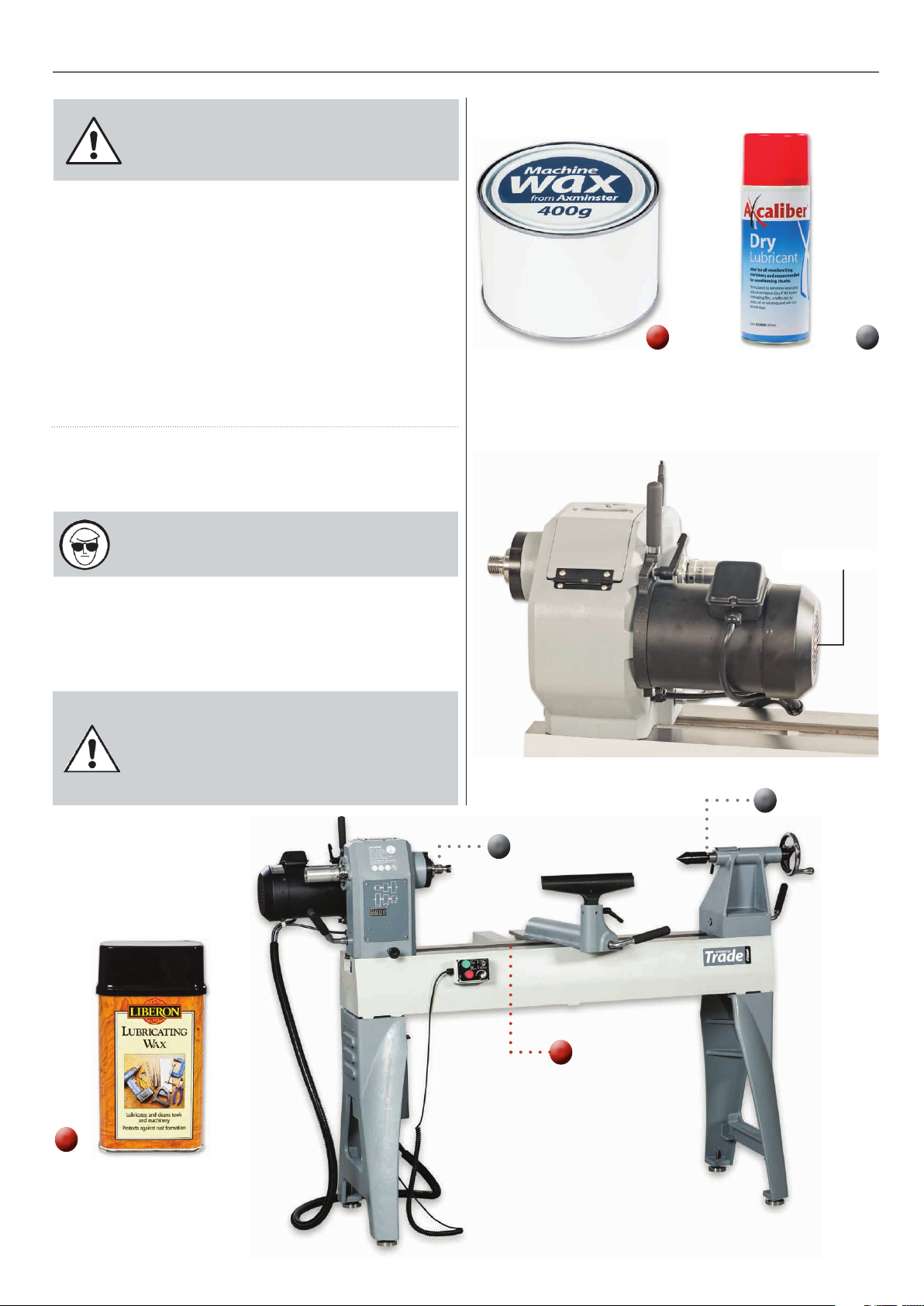
Daily After Use
• Clean wood shavings away from the lathe bed and tool rest.
• Smear a light coat of wax, ‘Axminster Machine Wax’, code
101582’ , see fig 68, over the lathe bed to allow the banjo and
tailstock to run more smoothly over the bed and to prevent
corrosion.
Maintenance
Fig 68-69
• Spray ‘Axcaliber Dry Lubricant’, code 503468, over the tailstock
barrel/live centre and headstock spindle/chuck after use, see fig
69.
Monthly
• Check the tension of the belt and adjust, (See pages 19 for
Changing the Belt Speed).
WARNING!! ALWAYS WEAR EYE
PROTECTION WHEN USING AN AIR LINE.
• Check any build up of wood shaving on the motor
and spindle pulleys and clean if necessarily.
• Also blow out the motor air vents, see fig 70.
NOTE: IF THE LATHE IS NOT GOING TO BE
USED FOR A PERIOD OF TIME, APPLY A
LIGHT COAT OF ‘LIBERON LUBRICATING
WAX’ OVER THE BED AND PLACE A DUST
SHEET OVER THE LATHE.
Axminster Machine Wax
Code: 101582
Axcaliber Dry Lubricant
Code: 503468
Fig 70
Motor air vents
Liberon Lubricating Wax
Code: 600221
21

Exploded Diagram/Parts List
22

Exploded Diagram/Parts List
PART NO
AT20-A01
AT20-A02
AT20-A03
AT20-A04
AT20-A05
AT20-A06
AT20-A07
AT20-A08
AT20-A09
AT20-A10
AT20-A11
AT20-A12
AT20-A13
AT20-A14
AT20-A15
AT20-A16
AT20-A17
AT20-A18
AT20-A19
AT20-A20
AT20-A21
AT20-A22
AT20-A23
AT20-A24
AT20-A25
AT20-A26
AT20-A27
AT20-A28
AT20-A29
AT20-A30
AT20-A31
AT20-A32
AT20-A33
AT20-A34
AT20-A35
AT20-A36
AT20-A37
AT20-A38
AT20-A39
AT20-A40
AT20-A41
AT20-A42
AT20-A43
AT20-A44
AT20-A45
AT20-A46
DESCRIPTION SPECIFICATION Q’ty
FACE PLATE 6” 1
SET SCREW 1/4”x3/8” 4
SPUR CENTER MT2 1
KEY 8 8*60 1
SPINDEL M33*P3.5 1
ROUND HEAD SCREW M6*10mm 4
BEARING 6209 2
WASHER M6 5
ROUND HEAD SCREW M5x12mm 13
COVER 1
HEADSTOCK 1
LATTER NIU 1
BELT COVER 1
ROUND HEAD SCREW M6x15 1
NUT CSTW-5 1
BELT 250J-10 1
SPINDLE PULLY 1
C RING S-22 2
TAP SCREW 1/4x1/2 2
CAP SCREW M5x25 6
COVER PLATE 1
DIGITAL READOUT 230V 1
CONTROL PLATE 1
CONTROL PANEL
ACRYLIC
TAP SCREW M3*10 4
FLAT HEAD SCREW M3x10 1
POSTION SET 1
NYLO NUT M3 4
WASHER M3 8
ROUND HEAD SCREW M3*35 2
MAGNET 1
BEARING 6208 1
GUK NYLON NUT M45 1
GUK NYLON NUT M40 1
HAND WHEEL 1
CORD PROTECTOR PG11(Long-Type) 1
WAVE WASHER BWW6201 1
NYLON NUT M5 4
BOLT 1
SET SCREW M6x12 4
HEADSTOCK BASE 1
FIXING PIECE 1
NYLO NUT 3/4” 1
HEADSTOCK SHAFT 1
C-RING S-9 1
SPRING 1
1
AT20-A47
AT20-A48
AT20-A49
AT20-A50
AT20-A51
AT20-A52
AT20-A53
AT20-A54
AT20-A55
AT20-A56
AT20-A57
AT20-A58
AT20-A59
AT20-A60
AT20-A61
AT20-A62
AT20-A63
AT20-A64
AT20-A65
AT20-A66
AT20-A66-1
AT20-A66-2
AT20-A66-3
AT20-A66-4
AT20-A66-5
AT20-A66-6
AT20-A66-7
AT20-A66-8
AT20-A66-9
AT20-A66-10
AT20-A66-11
AT20-A66-12
AT20-A66-13
AT20-A66-14
AT20-A66-15
AT20-A67
AT20-A68
AT20-A69
AT20-A70
AT20-A71
AT20-A72
AT20-A73
AT20-A74
AT20-A75
AT20-A76
AT20-A77
AT20-A78
AT20-A79
LOCK PIN 1
MOTOR PULLY 1
KEY 6*6*55 1
MOTOR 230V 50HZ 1
WASHER 3/8”xψ21x2.5 2
HANDLE 3/8” 1
MOTOR LABEL 1
SPRING WASHER 3/8” 1
CAP SCREW 3/8”-16uncx1-1/4 1
CORD PROTECTOR PG13.5 1
DOUBLE CONE 1
WIRE FIXING PIECE ACC-8 4
LOCK PIN 1
TAPERED SHAFT 1
KNOB 1
FACEPLATE WRENCH 1
POWER CORD 1
POWER CORD 2 1
MOTOR WIRE 1
CONTROL BOX 1
FED/REV SWITCH 1
PROTECTOR 1
SWITCH-GREEN 1
SWITCH-RED 1
VR CONTROL 1
VR NUT 1
BOX 1
MAGNET 1
CORD PROTECTOR PG9 1
SINGLE WIRE 1
CONTROL ACRYLIC 1
WIRE 1 1
WIRE 2 1
WIRE 3 3
LABLE 1
HORSE 1
GLOVE 1
MOTOR HANDLE 1
BEARING COVER 1
TOOTH WASHER M5 1
C-RING S-40 1
PMMA PLATE 1
POWER CORD 3 1
GLOVE 1
ROUND HEAD SCREW M5x30 1
WIRE FIXING PIECE ACC-3 1
SENSOR BRACKET 1
ROUND HEAD SCREW M3*25 2
23

Exploded Diagram/Parts List
24

Exploded Diagram/Parts List
PART NO DESCRIPTION SPECIFICATION Q’TY
AT20-B01 TOOL REST 12” 1
AT20-B02 LEVER 3/8” 1
AT20-B03 TOOLREST CARRIAGE 1
AT20-B04 C RING S-22 4
AT20-B05 BUSHING 2
AT20-B06 BOLT 1
AT20-B07 FIXING PIECE 2
AT20-B08 NYLON NUT 3/4” *10UNC 2
AT20-B09 ECCENTRIC SHAFT 1
AT20-B10 SET SCREW 5/16”X1/4” 1
AT20-B11 LIVE CETER MT2 1
AT20-B11-1 LIVE CENTER ROD 1
AT20-B12 LABEL 1
AT20-B12-1 IC BOARD 1
AT20-B13 QUILL 1
AT20-B14 DIGITAL READER 1
AT20-B15 SET SCREW M3X6 4
AT20-B16 NUT M10 1
AT20-B17 SET SCREW M10X30 1
AT20-B18 LEVER 5/16” 1
AT20-B19 CORD PROTECTOR PG13.5 2
AT20-B20 TAILSTOCK SCREW 3/4”-16UNF 1
AT20-B21 SET SCREW 5/16”*1/4” 2
AT20-B22 HANDWHEEL 1
AT20-B23 HANDLE 1
AT20-B24 NUT M5 2
AT20-B25 ECCENTRIC SHAFT 1
AT20-B26 STOP RING 1
AT20-B27 TAILSTOCK 1
AT20-B28 BOLT 1
AT20-B29 BIG ROUND HEAD
SCREW
AT20-B30 THRUST WASHER WTM-2036-015 1
AT20-B31 NAME LABEL 2
AT20-B32 STOP ROD 2
AT20-B33 BED 1
AT20-B34 INVER BOX-DOWN 1
AT20-B35 ROUND HEAD SCREW M5X12 2
AT20-B36 INVERTER 3HP 1
AT20-B37 FLAT HEAD SCREW M4X15 4
AT20-B38 INVER BOX-UP 1
AT20-B39 ON/OFF SWITCH 1
AT20-B40 LABEL 1
AT20-B41 HEX SCREW M10X50 8
AT20-B42 BREAK 1
AT20-B43 NUT M4 4
AT20-B44 CORD PROTECTOR PG9 2
AT20-B45 CORD PROTECTOR PG11 1
AT20-B46 TOOL REST 6” 1
AT20-B47 GLOVE 19*100 1
AT20-B48 GLOVE 19*140 1
AT20-B49 ROUND HEAD SCREW M6X20 2
AT20-B52 COVER-DOWN 1
AT20-B53 COVER-UP 1
AT20-B54 NUT M3 2
AT20-B55 ROUND HEAD SCREW M3X10 2
AT20-B56 ROUND HEAD SCREW M3X5 2
AT20-B57 ID LABEL 1
AT20-B58 WARNING LABEL 1
AT20-B59 NYLON NUT M3 2
M4X10 4
25

Exploded Diagram/Parts List
26

Exploded Diagram/Parts List
PART NO. DESCRIPTION SPECIFICATION Q’TY
AT20-C01 STAND 2
AT20-C02 WASHER M10 8
AT20-C03 SPRING WASHER M10 8
AT20-C04 HEX HEAD SCREW M10X40 8
AT20-C05 NUT 1/2”-12UNC 4
AT20-C06 ADJUSTABLE LEVELER 1/2”-12UNC 4
PART NO DESCRIPTION (BAT20 BE) SPECIFICATION Q’TY
1 EXTEND BED 1
2 CAP SCREW M10X45 4
3 WASHER M10 4
4 EXTEND ROD 1
5 LOCK HANDLE 3/8* 1
6 SPRING WASHER M10 4
27

Wiring Diagram
28

Notes
29

Notes
30

Notes
31

The Axminster guarantee is available on
Craft, Trade, Engineer, Air Tools & CNC Technology Series machines
Buy with confidence from Axminster!
So sure are we of the quality, we cover all parts and labour free of charge for three years!
For more information visit axminster.co.uk/3years
The packaging is suitable for recycling.
Please dispose of it in a responsible manner.
EU Countries Only
Do not dispose of electric tools together with household waste material.
By law they must be collected and recycled separately.
Axminster Tools & Machinery
Axminster Devon EX13 5PH
axminster.co.uk
 Loading...