

Page 1
APOHCG
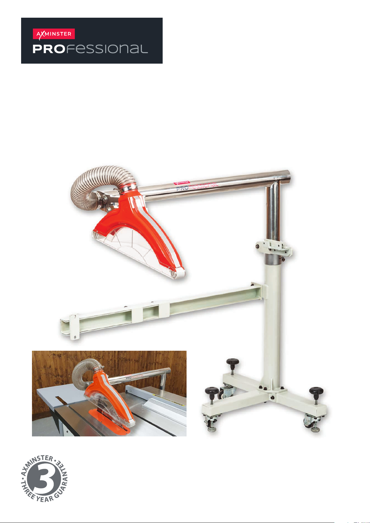
Overhead Crown Guard
Code 109594
Original Instructions
AT: 20/06/2023
BOOK VERSION:
01
Page 2
INDEX OF CONTENTS
Assembly 02-04
Attaching to the Saw 05-06
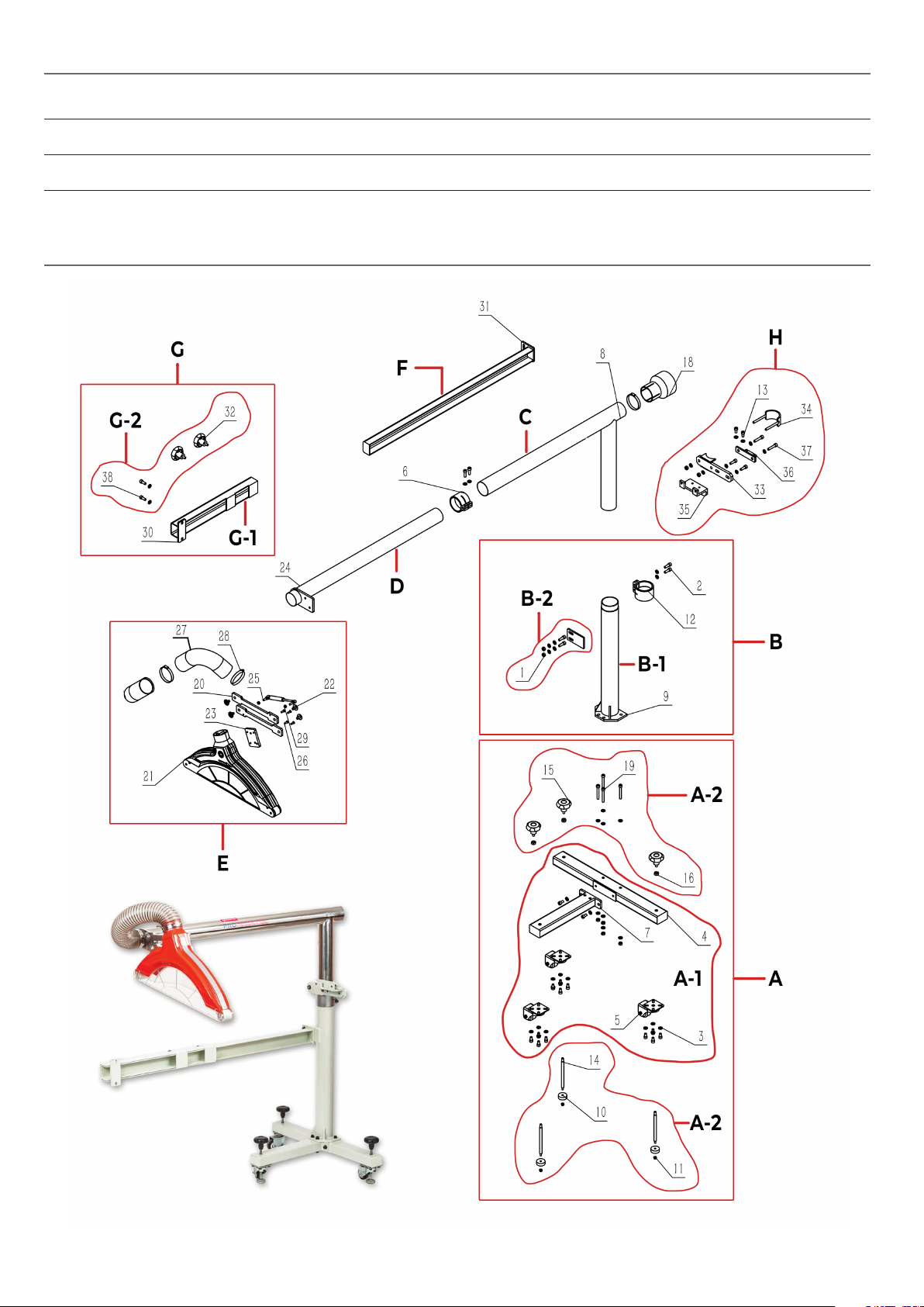
Exploded Diagram 07
ASSEMBLY
2
Page 3
ASSEMBLY
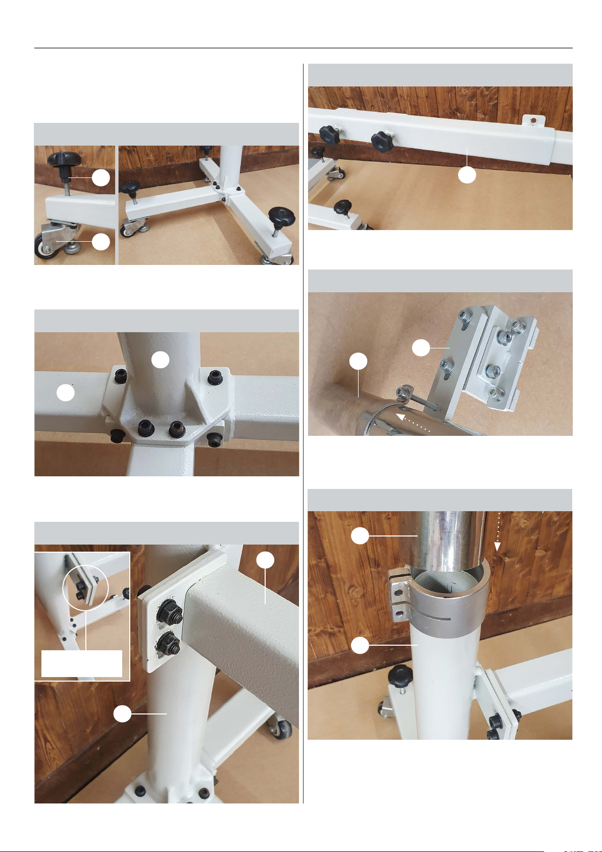
1. Thread the 3 levelling feet(A2) through the swivelling
casters fitted to base frame (A1) from the underneath
then thread on the nut & the knob. Lock nut & knob
together, see fig 01-02.
Fig 01-02
A2
A1
2. Using the 4 x M8 x 60mm Cap bolts bolt the vertical
column(B1) to base frame (A1), see fig 03.
Fig 03
B1
Fig 06
G1
4. Slide the extending support bracket(G1) on to support
arm (F), thread in loosely the 2 x M8 knobs, see fig 06
Fig 07
H
C
A1
3. Using 2 x M8 x 25mm Cap bolts, bolt the support arm
(F) to the vertical column(B1), see fig 04-05.
Fig 04-05
F
M8 x 25mm
Bolts
5. Slide the table clamp bracket assembly (H) over the
chrome vertical guard support arm (C), lock loosely in
place around halfway up, see fig 07.
Fig 08
C
B1
B1
6. Slide the chrome vertical guard support arm(C) into
vertical column(B1), lock loosely in place with 2 x M8 x
25mm Cap bolts washers & nuts, see fig 08.
3
Continues over...
Page 4
ASSEMBLY
Fig 09
C
Fig 10
D
Clamping tube collar
Fig 12
D
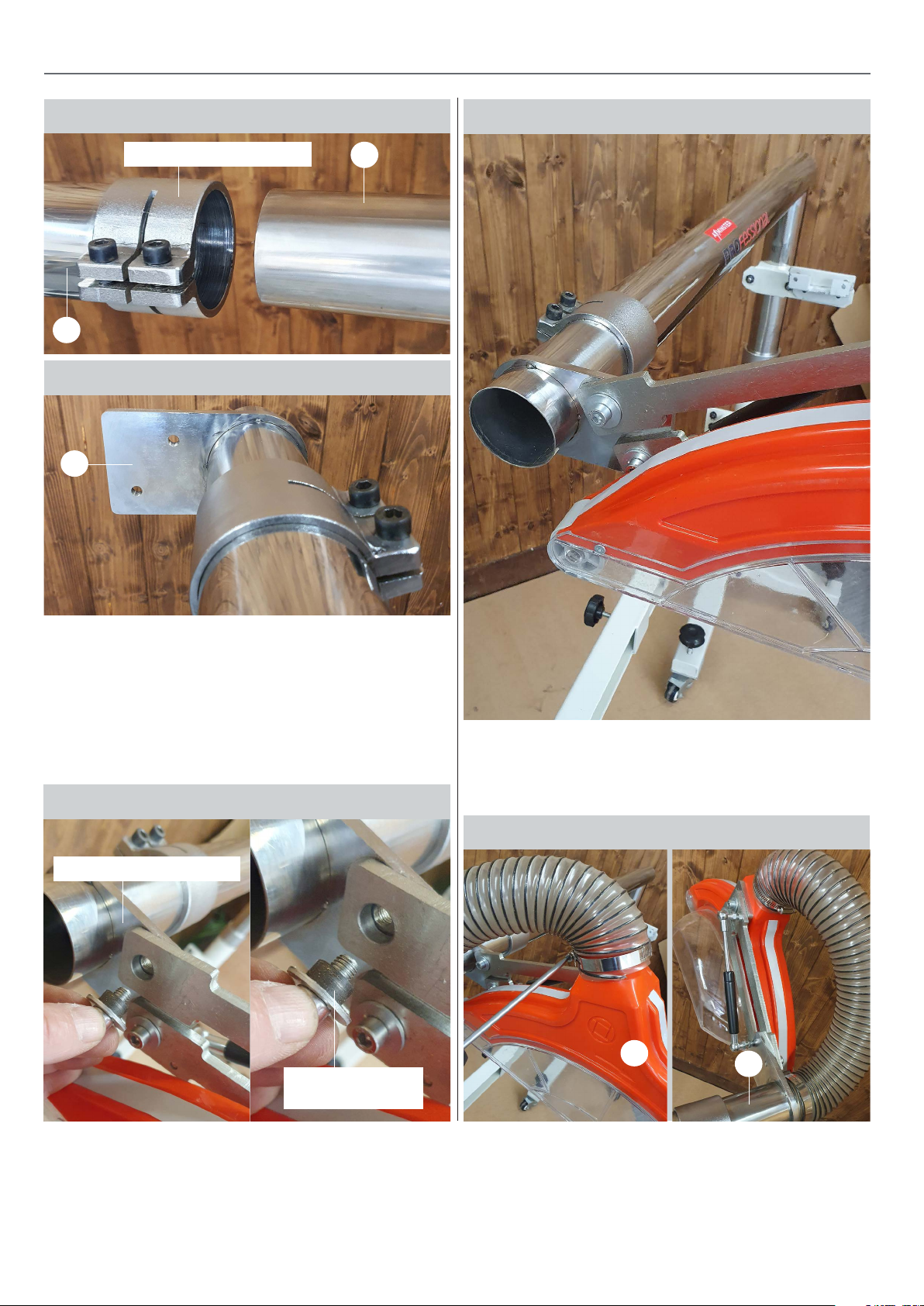
7. Slide chrome horizontal extending guard support
arm (D) into chrome vertical guard arm (C), lock in place
with the guard mounting plate parallel to the floor, see
fig 09-10.
8. Attach the guard (E) to the to the guard mounting
plate using the 2 x M8 Cap bolts with bushes, tighten
in place, see fig 11-12.
Fig 11
Guard mouting plate
M8 Cap bolts
with bush
9. Connect the 63mm extraction hose to the guard(E)
and the end of the chrome horizontal extending guard
support arm(D) using the hose clips, see fig 13-14.
Fig 13-14
E
D
4
Page 5
ATTACHING TO THE SAW
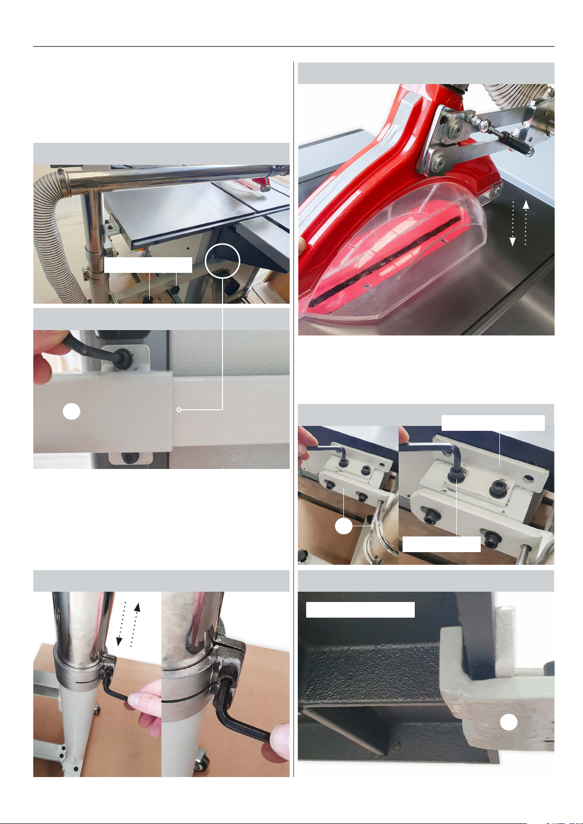
1. Lower the saw blade beneath the table.
2. Ensuring that the levelling feet(A2) are raised up, wheel
the overhead guard kit to the table saw and position it on
the far-right hand side of the saw and position the guard
approximately over the table insert, see fig 15.
Fig 15
Clamping knobs
Fig 16
Fig 18
5. Lock the table clamping bracket assembly (H) against
the table with the 2 x M8 Cap bolts, see fig 19-20. Note:
the two holes (A) in the clamping bracket are not used,
these holes are present to help retrofit the guard kit
to other brand table saws, see fig 21 on page 06.
G1
3. Connect the extending support bracket(G1) to the back
of the saw with the x 2 M8 cap bolts, leaving the clamping
knobs loose at this point, see fig 15-16.
4. Pivot the guard downwards then adjust the height of
the column so that the guard makes light contact with
the table, lock in place, see fig 17-18.
Fig 19
H
Fig 20Fig 17
Underside of table
Clamping bracket
M8 Cap bolt
H
5
Continues over...
Page 6
ATTACHING TO THE SAW
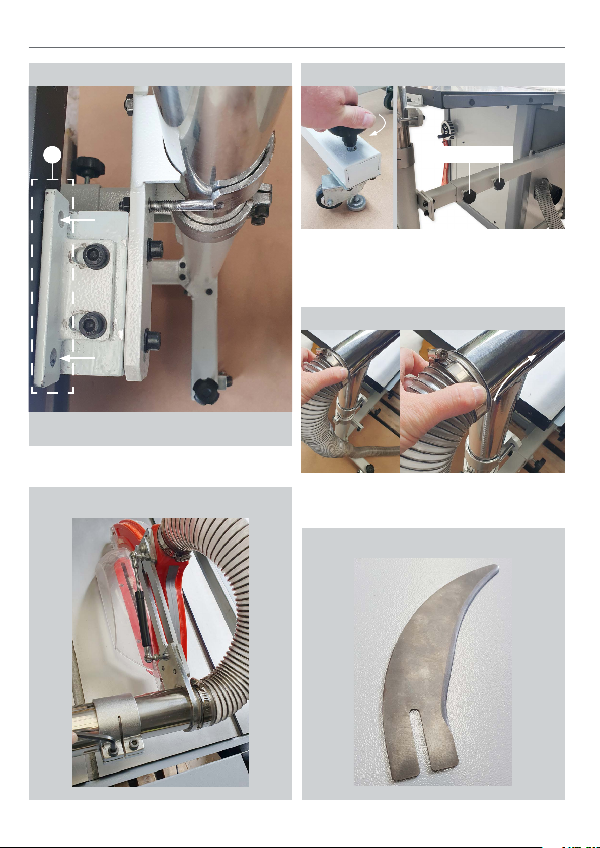
Fig 21
A
Fig 23-24
Clamping knobs
7. Wind down the feet for extra stability & levelling then
lock the 2 x M8 clamping knobs on the extending
support bracket (G1), see fig 23-24.
8. Connect the 63mm hose, see fig 25.
Fig 25
These holes are present to help retrofit the guard kit
to other brand table saws.
6. Centralize & level the saw guard to the table insert &
table, see fig 22.
Fig 22
The AP254SB and AP3055SB come with a stub riving
knife which is intended to be used when this guard
is fitted, see fig 26.
Fig 26
6
Page 7
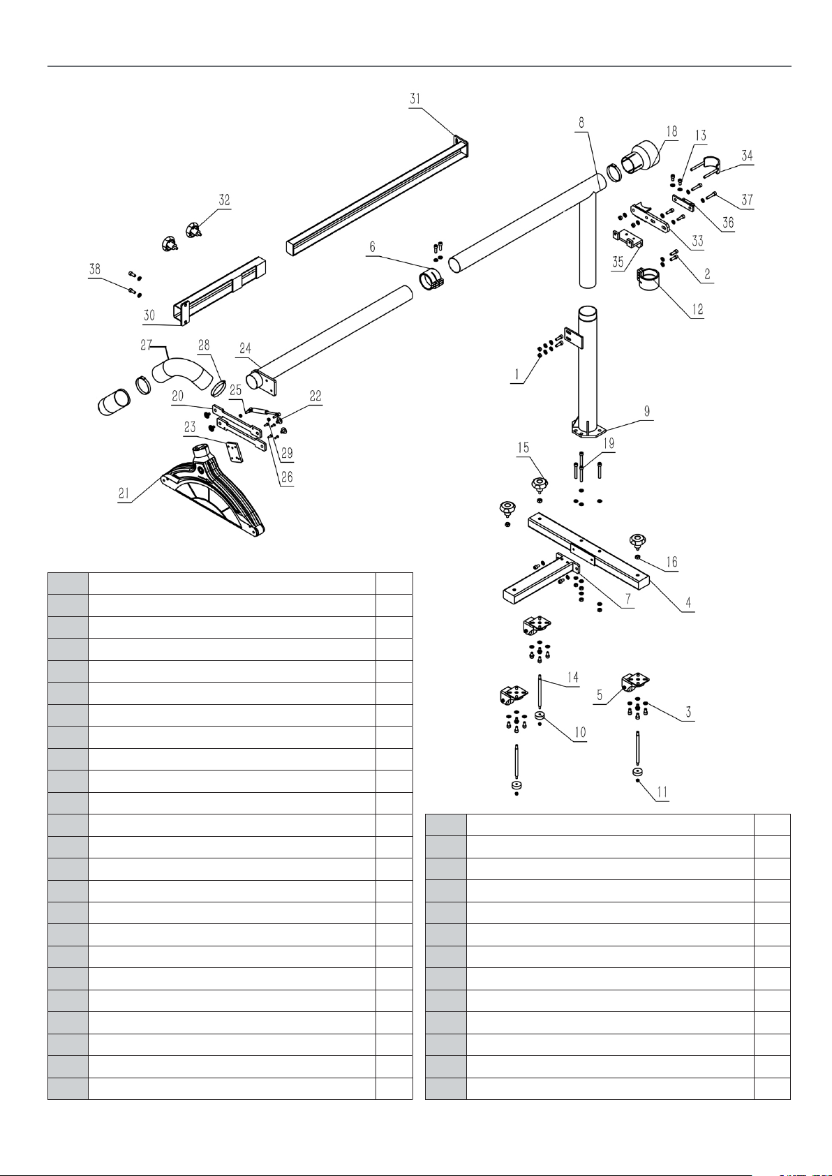
EXPLODED DIAGRAM
No. Description QTY
1 Hex.Nut M8 8
2 Hex.Socket Cap Head Screw M8X25 8
3 Washer 8 41
4 Long Support 1
5 Roll Wheel 50 3
6 Hose Clamps 1
7 Extension Bracket 1
8 Blade Guard Bracket A 1
9 Stand Up Leg 1
10 Leveling Foot 3
11 Hex.Locking Nut M6 3
12 Locking Hose Hoop 1
13 Hex.Socket Cap Head Screw M8X16 17
14 Screw Rod,Foot 3
15 Locking Knob 3
16 Hex.Nut M10 3
19 Hex.Socket Cap Head Screw M8X25 4
20 Connection Board 2
21 Blade Guard 1
22 Step Bolt 4
23 Mounting Plate 1
24 Blade Guard Bracket B 1
25 Gas Spring 1
26 Hex.Socket Countersunk Screw M6X8 4
27 Dust Collection Hose 2
28 Hose Clamp 51-70 3
29 Hex.Nut M6 2
30 Supporting Bracket A 1
31 Supporting Bracket B 1
32 Locking Knob 2
33 Fixed Block 1
34 U Shape Clamp 1
35 Connection Block 1
36 Pad Board 1
37 Hex.Socket Cap Head Screw M8X40 2
38 Hex.Socket Cap Head Screw M8X20 2
7
Page 8
The Axminster guarantee
Buy with confidence from Axminster Tools!
So sure are we of the quality, we cover all parts and labour free of charge for three years!
For more information visit axminstertools.com/3years
The packaging is suitable for recycling.
Please dispose of it in a responsible manner.
EU Countries Only
Do not dispose of electric tools together with household waste material.
By law they must be collected and recycled separately.
Axminster Tools, Axminster Devon EX13 5PH
axminstertools.com
 Loading...