

Page 1
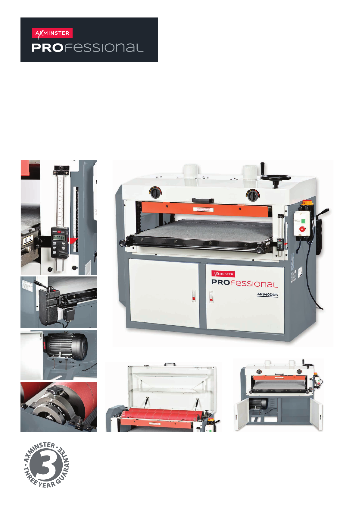
AP940DDS
Dual Drum Sander
Code 107639
Original Instructions
AT: 30/08/2022
BOOK VERSION: 5
Page 2
Cert No: 3408, 3409
Axminster Tool Centre Ltd
Axminster Devon
EX13 5PH UK
EU Declaration of Conformity
This machine complies with the following directives:
axminstertools.com
declares that the machinery described:-
Type
Model
Signed
Andrew Parkhouse
Operations Director
Dual Drum Sander
AP940DDS
Date: 26/03/2018
2006/42/EC
EN ISO 12100: 2010
EN 60204-1: 2006/AC: 2010
EN ISO 19085: 2017
and conforms to the machinery example for which the
EC Type-Examination Certificate No RA/2018/30001C
has been issued by Yeon Chuan Machinery Co., Ltd.
at: 50-2, Lane 108, Yongfeng RD., Taiping Dist., Taichung City, Taiwan 411
and complies with the relevant essential health and safety requirements.
Page 3

THANK YOU for choosing this Horizontal Double Drum Sanders.This Horizontal
Double Drum Sanders has been carefully tested and inspected before shipment and if properly used
and maintained, will provide you with years of reliable service. To ensure optimum performance and
trouble-free operation, and to get the most from your investment , please take the time to read this
manual before assembling, installing and operating the unit.
you with the safe operation, basic function, and features of this
as well as the set-up, maintenance and identification of its parts and com
The manual's purpose is to familiarize
Horizontal Double Drum Sanders
ponents. This manual is
not intended as a substitute for formal woodworking instruction, nor to offer the user instruction in
the craft of woodworking. If you are not sure about the safety of performing a certain operation or
procedure, do not proceed until you can confirm
that it is safe to do so.
f
uture reference
Disclaimer: The information and specifications in this
manual pertain to the unit as it was supplied from the
factory
at
the time of printing. Because we are committed
to
making constant improvements, we reserves the right to
make changes to components, parts or Features of this
unit as deemed necessary, without
prior notice and without obligation to install any such
changes
t
aken at the fact
in
with which it
on
f
ormation in t
previously delivered units.
.
ory to
ensure that the
his manual corresponds with that of the unit
nce you've read through these instructions, keep this manual handy for
O
Reasonable care is
specifications and
, f
rom knowledgeable and qualified sources
was supplied. However, special orders and "after
f
actory" modifications may render some or all
information in this manual inapplicable to your machine
F
urther, as several generations o
Horizontal Double Drum Sanders
o
f t
his manual may be in circulation, if you own an
earlier
or
later version of this unit, this manual may no
depict your machine exactly
ques
tions contact your retailer or our support line with
model and serial number of your uni
the
clarification
.
f t
his model o
and several versions
. If
you have any doubts or
t for
,
.
f
t
Page 4

SAFETY RULES
READ CAREFULLY BEFORE OPERATING THE MACHINE
1. Learn the machine's applications and limitations, as
well as the specific potential hazards particular to this
machine. Follow available safety instructions and
safety rules carefully .
2. Keep working area clean and be sure adequate
lighting is available.
3. Do not wear loose clothing, gloves, bracelets,
necklaces, or ornaments. Wear face, eye, ear, respiratory and body protection devices, as indicated for the
operation or environment.
4. Keep hands well away from sanding belt and all
moving parts. Do not clear chips and sawdust away
hands. Use a brush.
5. Make sure the belt is moving at operation speed
before sanding.
6. Do not push the sanding belt to hard. The belt will
perform better and be safer working at the rate for
which it was designed.
with
13. Use suitable support if stock does not have a flat
surface.
14. Do not force the machine. It will do the job better
and be safer at a rate for which it was designed.
15. Keep guards in place and in working order. If a
guard must be removed for maintenance or
cleaning make sure it is properly attached before
using the tool again.
16. Be sure that key and adjusting wrenches have
been removed before turning power on.
17. Use only accessories designed for the machine.
18. Make sure tool is properly grounded. If tool is
equipped with three-prong plug, it should be
plugged into a three-pole electrical receptacle.
Never remove the third prong.
19. Always disconnect tool before servicing and when
changing accessories such as sanding belts.
7. Whenever possible use a dust collector with shaving
hood to minimize health hazards.
8. Never leave the machine with the power on.
9. Keep children away. Make sure that visitors are kept
safe distance from the work area.
10. Use recommended speed sanding accessory, and
workpiece material.
11. Never stand on tool. Serious injury could occur if the
is tipped or if the sanding tool is unintentionally
contacted.
12. Be sure sanding belts are securely locked in the
machine.
at a
tool
20. Make sure that switch is in "OFF" position before
plugging in cord.
21. Hold material firmly against the table.
22. Use ONLY recommended accessories. Use of
accessories NOT recommended
risk of injury.
23. Do not use this sanding machine for other than it's
intended use. If used for other purposes, General
International disclaims any real or implied
warranty and holds itself harmless for any injury,
which may result from that use.
may result in a
Page 5
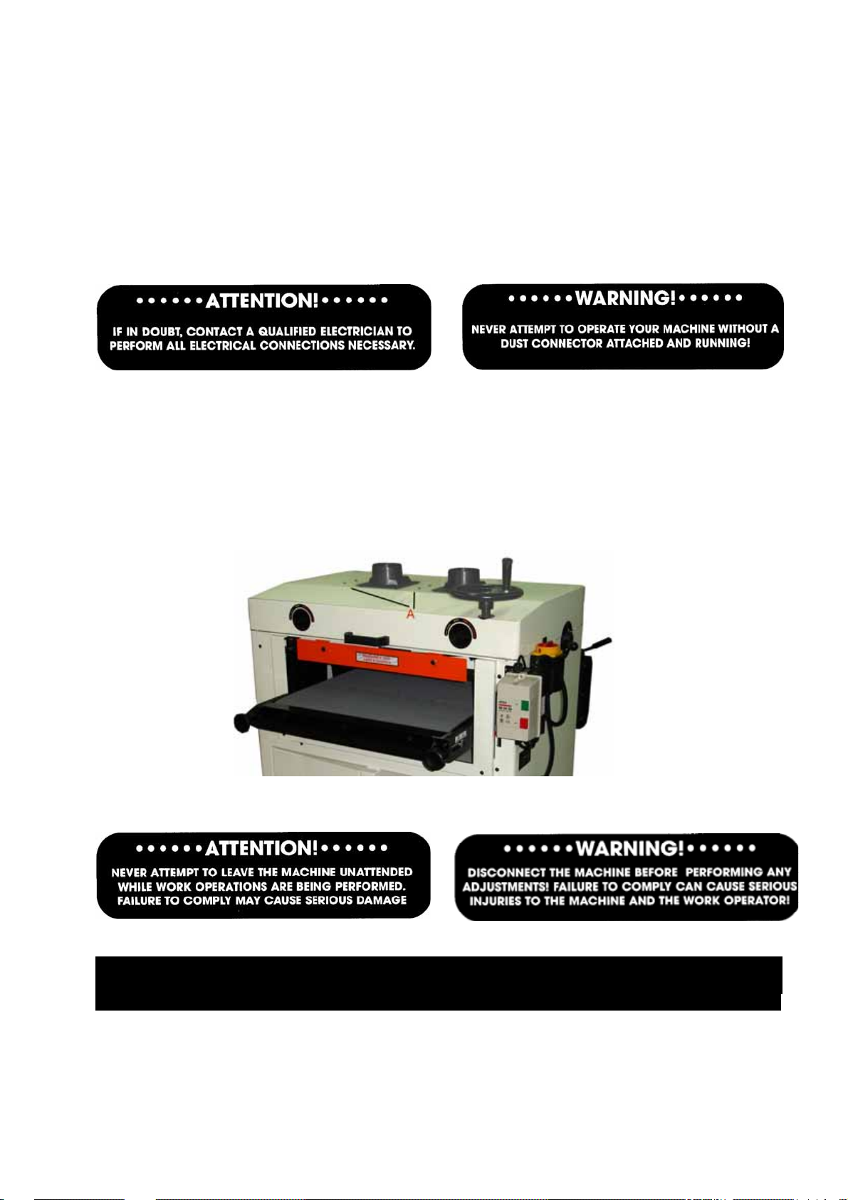
GROUNDING
Machine must be properly grounded in order to avoid ele ctric shock to the work operator. The use of
an extension cord is not recommended, if necessary use an extens ion cord and outlet the total length
between the fuse and the connection terminal must not exceed 1.5m (immediately replace the
extension cord if worn out, cut or damaged). If in doubt contact a qualifled electrician.
Connect to a circuit breaker no greater than voltage suppplied on name plate, to avoid shock or fire
DUST COLLECTOR CONNECTION
The 25" horizontal drum sander is equipped with two 4" dust hood outlets. Ring clamps must
be used to connect the dust collection hoses to the chutes.
Use 4 phillips head screws and flat washer,
the hole of dust chute to cover. Tighten the
attach the dust chute to the cover(A, Fig 2).Align
phillips head screws
.
It is recommended to attach a 3HP dust collector to have efficient suction.
Fig.2
DISCONNECT THE MACHINE FROM THE POWER SOURCE BEFORE PERFORMING ANY ADJUSTMENTS!
WARNING!
4
Page 6
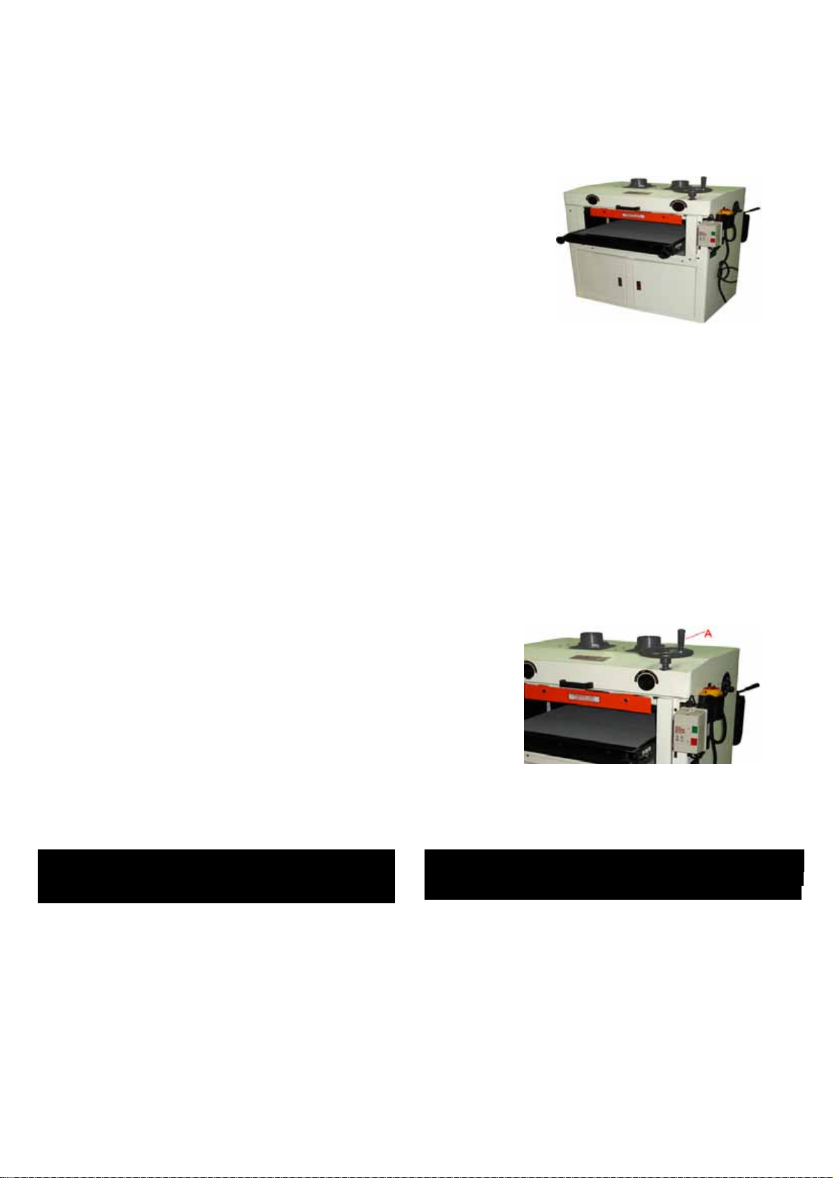
37" HORIZONTAL DOUBLE DRUM SANDER
Horizontal Double Drum Sanders are carefully
tested and inspected before shipment and if properly used will give perfect
results. However, a reasonable amount of care and attention is necessary to
ensure perfect performance and accurate work. It is imperative that you take
a few moments to familiarize yourself with these instructions, as they will no
doubt save you a lot of time and trouble .
UNP ACKAGE AND CLEANUP
To ensure maximum performance from your 25" Sander, clean it properly; and
Install it accurately before use. As soon as you receive this machine, we recommend you follow these procedures:
1. Finish removing the contents of the shipping wooden case and compare with the contents list .
2. Report damage, if any to your local distributor
3. Clean all rust protected surfaces with a mild solvent or kerosene. Do not use lacquer thinner paint thinner or
Gasoline. These will damage painted surfaces .
4. To prevent rust,apply alight coating of paste wax to surface .
TRANSPORT
Transport the machine to the required work area with the use of
a forklift. The equipment used for the transportation must be of
adequate capacity to move sander .
Install the table elevation handwheel as A,Fig.1. The slots on
the shaft and handwheel must be aligned, fasten the handwheel
to the shaft with the pin supplied.
Fig.1
• • • • • • • • • • • • •
NEVER ATTEMPTT OCONNECT TO ANOUTLT WITH A
GREATER POWER SOURCE VOLTAGE THAN REQUIRED !
CAUTION !
• • • • • • • • • • •
• • • • • • • • • • • • •
ALWAYS VERIFY THAT THE MACHINE IS PROPERLY GROUNDED
TO AVOID ELECTRIC SHOCK TO THE WORK OPERATOR !
ATTENTION !
•• • • • • • • • • • • •
ELECTRICAL REQUIREMENTS
Before connecting the machine to the power source verify that the voltage supplied corresponds as specified
on the nameplate of the machine. A power source with greater voltage than needed can result in serious injury
to the user as well as damage the machine. if in doubt, contact a qualified electrician before connecting to the
power source.
3
Page 7
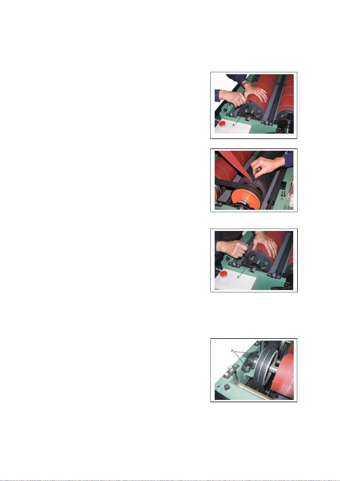
CHANGING SANDING PAPER
In order to access the sanding drums; lift and tilt the upper
guard towards the rear.
To remove the sanding belts:
1. Disconnect the machine from the power source
before replacing the sanding belts.
2. Loosen the press blocks(A,Fig.3) at both sides. Unwind
the sanding belt from the drum.
3. Insert the new sanding belt into the press block of left hand Fig.3
and tighten the block.(Fig.4)
4. Hold the sanding belt and rotate the drum forward to tighten
the pull ring. Roll the sanding belt onto the drum, keep the
edges snug.
5. Insert the tab (right end of the sanding belt) into the press
block at the other end of the drum and tighten the block.
6. Use open wrench to loosen two hex screws. Hold the belt
on the drum and rotate the pull ring till the belt is fully Fig.4
tight then fasten the screws.(A,Fig.5)
7. After using the sander for some period of time, the wood
chips may attach on the surface of the sanding paper. If
the wood chips are not removed or cannot be removed,
you must replace your sanding paper with the proper
grits #60, #80, #100, #150, #180, #240,,,etc. You may select
the cuts in sizes, or the full roll 4" (101.6 mm) and cut the
sizes yourself. Follow the size of the used sanding paper .
The rear sanding drum should be fitted with a finer sanding
paper than the front, allowing for coarse and fine sanding to be
achieved with one pass.
SANDING DRUMS ADJUSTMENT
The sanding drums have been factory adjusted and need
no further adjustment. The sanding drums must be adjusted
for parallelism.
Each drum is supported by two sets of bearing seats and can
be adjusted individually (A,Fig.6).
To adjust follow the procedures:
1. Loosen 2 hex screws (A,Fig.6) and nut under the bearing
seat(B,Fig.7).
Fig.6
5
Fig.5
Page 8
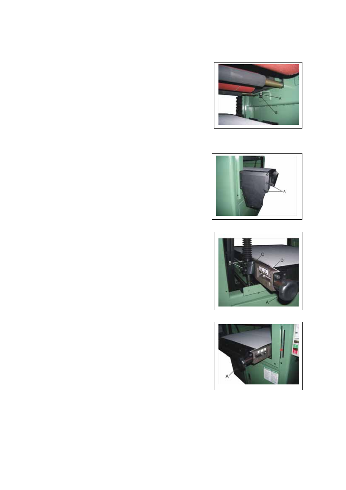
2. Turn screw (A,Fig.7) clockwise to raise the drum
and counter-clockwise to lower the drum. Place a gauge
block under the drum to adjust the parallelism.
Fig.7
CHANGING THE CONVEYOR BELT
It is extremely important that the conveyor belt be r eplaced
once damaged or worn out. If the belt is not changed your
work operations will not result in satisfactory projects. To
replace:
1. Remove 4 cap screws of reducer (A,Fig.8) and dismantle
the reducer.
2. Remove knobs (A,Fig.9) and 4 cap screw (B,Fig.9)from
four screw blocks (C,Fig.9).
Fig.8
3. Remove the table and roller bracket (D,Fig.9) to take out
the damaged or worn out conveyor belt. Replace new
conveyor belt.
4. Assemble back parts by reverse procedures.
Fig.9
CONVEYOR BELT ADJUSTMENT
The conveyor belt may slide to the right or left during
operations, or the tension of the conveyor belt is too loose
or too tight. To adjust follow these procedures:
Turn the adjustment knobs (A,Fig.10) on either side of
the conveyo r table.
The conveyor belt should run at the center of the
conveyor table, and should be tensioned so that there is
good traction during stock feeding Fig.10
6
Page 9
Page 10
SANDING OPERATIONS
The maximum workpiece thickness allowed for the
Drum Sander is 135 mm. Never attempt to sand
workpiece greater or less than the mentioned
dimensions; attempting to will cause serious injuries to
the work operator and damage your machine. A normal
cut is better not over 0.50mm. Excessively heavy cut can
cause wood burning or jamming.
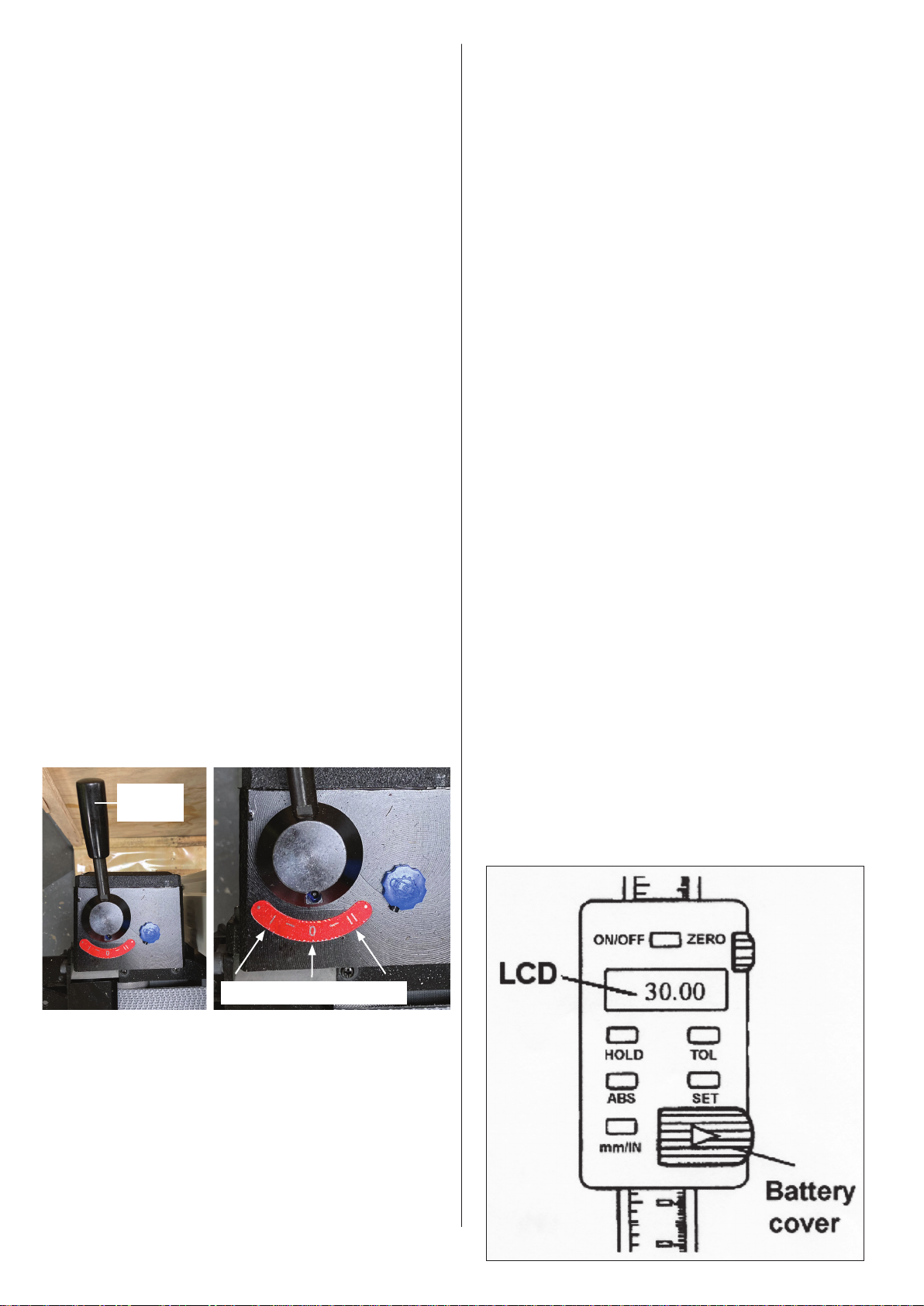
ON/OFF
• Press ON/OFF button to power on. Press ON/OFF button
3 seconds for power off.
Incremental Measurement (INC)
• Is used to display the amount of material to be
removed from a workpiece. Press ABS button until “INC”
appears.
1. Always remove tools or parts that have been left on
the machine before turning on you sander. Verify that
the top cover is secure and tightened.
2. The two speed dial located on the control box
3. Start the dust collector.
4. Place workpiece on the table and turn the hand wheel
until the workpiece can be sanded. Remove the
workpiece from conveyor table.
5. Press the green button to start the drum motor and
feed motor.
6. With the machine running move the speed control
handle to the required feed speed, see fig (A). A slower
feed rate can sand the surface smoother but will burn the
wood sometimes. A faster feed rate can remove material
faster but please watch the load meter to avoid
overloading your machine.
7. Pass the workpiece through the sander and make
multiple passes and check the workpiece is smooth or
not.
8. New sanding belt may become loose after numerous
sanding projects. Rewind the sanding belt if needed.
Fig A
Control
Handle
Reset to Zero
• Press the ON/OFF button to reset to zero.
Absolute Measurement (ABS)
• This function is not generally used in sanding
operations.
• To calibrate: Sand a board and measure the thickness.
• Without moving the table, press the SET button - the
indicator will flash “SET”.
• Press and hold the SET button until the digit you want
flashes.
• Press SET (no longer than 1 second), the digit will
increase by one each time until SET is pressed.
• When finished, press and hold the SET button until
indicator “SET” flashes.
• Press SET again (no longer than 1 second). The indicator
“SET disappears and the value you just input is displayed
on the LCD.
• The setting will be kept in the memory, even when the
diaital display is turned off.
• It only needs resetting after battery replacement.
• IMPORTANT: Always place the digital display in “’INC”
mode before turning it off. Default to zero. If you tum
it off while in “ABS” mode, your absolute setting will
disappear.
2m/min – Stop – 3m/min
Digital Scale
• The digital scale (Fi& 6) can be used to display
the depth of cut.
• This device uses a 1.5-volt battery cell (SR44 or G-13A).
• If it needs replacing, slide off the battery cover.
The +pole of the battery is facing out.
8
Page 11
Page 12
Page 13
Page 14
Page 15
Page 16
Page 17
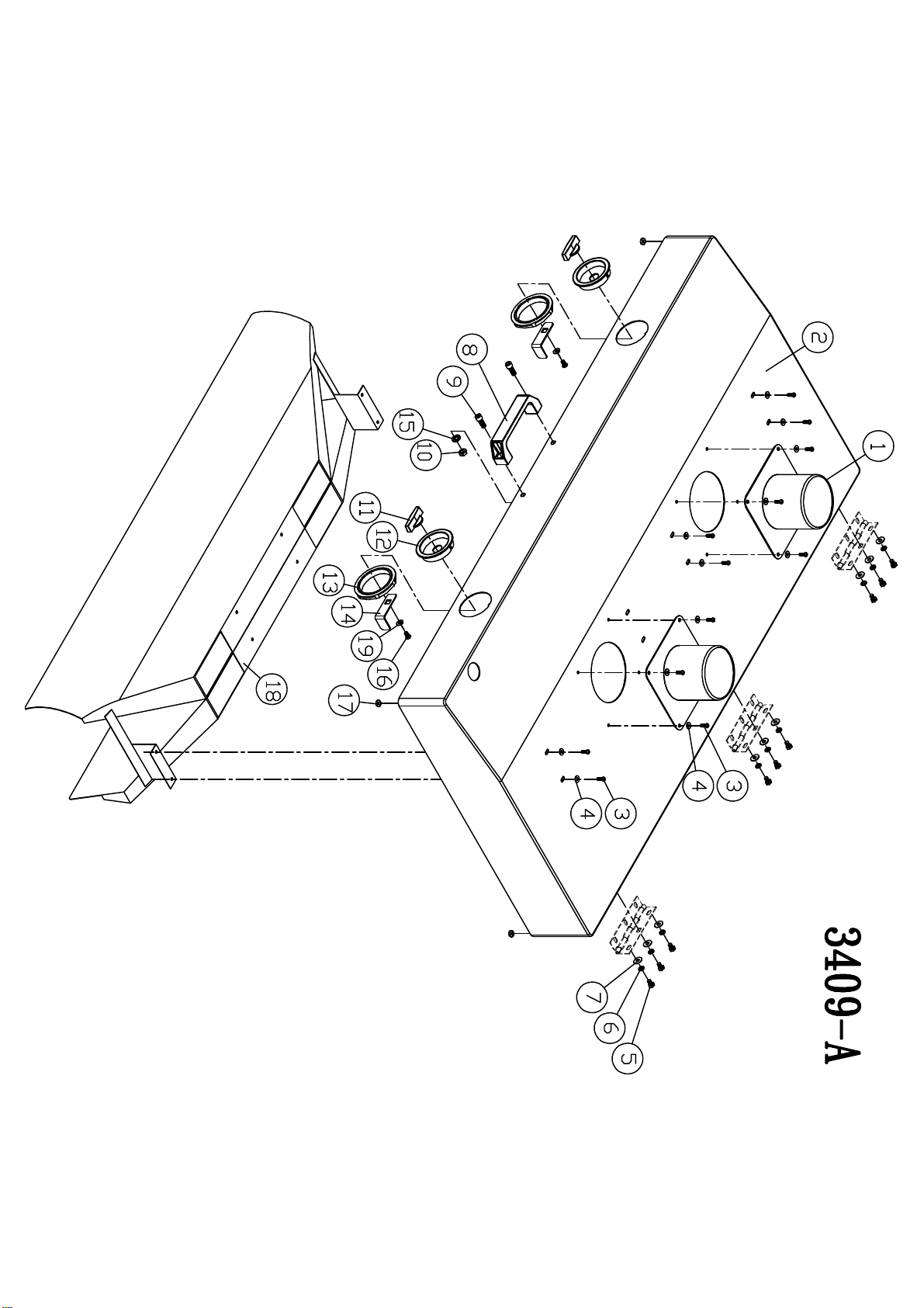
NO. REF.
Part No.
DESCRIPTION Specifiction QTY
3409-A01
1 34081002
Dust Chute
2
3409-A02
2 34091002
Cover
1
3409-A03
3 50154004
Round Head Screw
3/16"-24UNC*1/2" 16
3409-A04
4 50351046
Washer
3/16"*12*1t 16
3409-A05
5 50151088
Hex Head Screw
1/4"-20UNC*1/2"L 9
3409-A06
6 50352002
Lock Washer
1/4" 9
3409-A07
7 50351003
Washer
1/4"*13*1t 9
3409-A08
8 34011025
Handle
1
3409-A09
9 50152027
Cap Screw
5/16"-18UNC*3/4"L 2
3409-A10
10 50251035
Nut
5/16"-18UNC 2
3409-A11
11 34021024
Cover Lock Knob
2
3409-A12
12 34021023
Cover Lock Base
2
3409-A13
13 34021025
Cover Lock Nut
2
3409-A14
14 34021018
Cover Lock
2
3409-A15
15 50352003
Washer
5/16" 2
3409-A16
16 50161047
round Head Screw
1/4"*1/2"L 2
3409-A17
17 34021031
Buffer
4
3409-A18
18 34031013
Dust Collect body
1
3409-A19
19 50351057
Flat washer
1/4"*16*1t 2
NO. REF.
Part No.
DESCRIPTION Specifiction QTY
3409-B01
1 34082001
Bearing Housing Base
2
3409-B02
2 50506001
Bearing
UCC 205-16 2
3409-B03
3 50402010
C-ring
RTW-80 2
3409-B04
4 50113003
Star Knob
M8*1.25P*25L 2
3409-B05
5 34062003
Sanding Belt Clamp(L)
2
3409-B06
6 50103042
Set Screw
M10*1.5P*10L 4
3409-B07
7 50401022
C-ring
STW-100 2
3409-B08
8 34012008
Pulley
2
3409-B09
9 50152023
Cap Screw
5/16-18UNC*1/2"L 4
3409-B10
10 34012004
Spring
2
3409-B11
11 34022040
Abrasive Fastener-left
2
3409-B12
12 50604015
Key
8*7*50L 2
3409-B13
13 34092001
Sanding Drum
2
3409-B14
14 34012005
Sanding Belt Clamp Block
4
3409-B15
15 50152004
Cap Screw
1/4"-20UNC*1"L 4
3409-B16
16 34022039
Abrasive Fastener-Right
2
3409-B17
17 50351055
Flat washer
3/8"*28*3t 4
3409-B18
18 50352004
Spring washer
3/8" 12
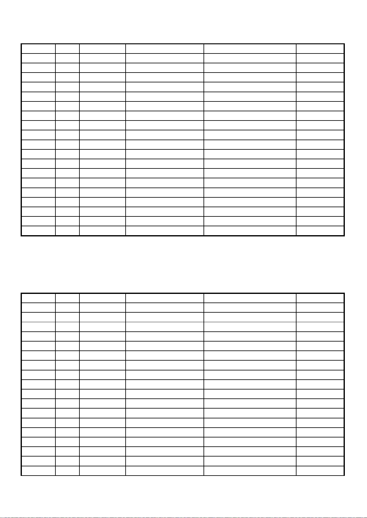
3409 - A DUST CHUTE ASSEMBLY
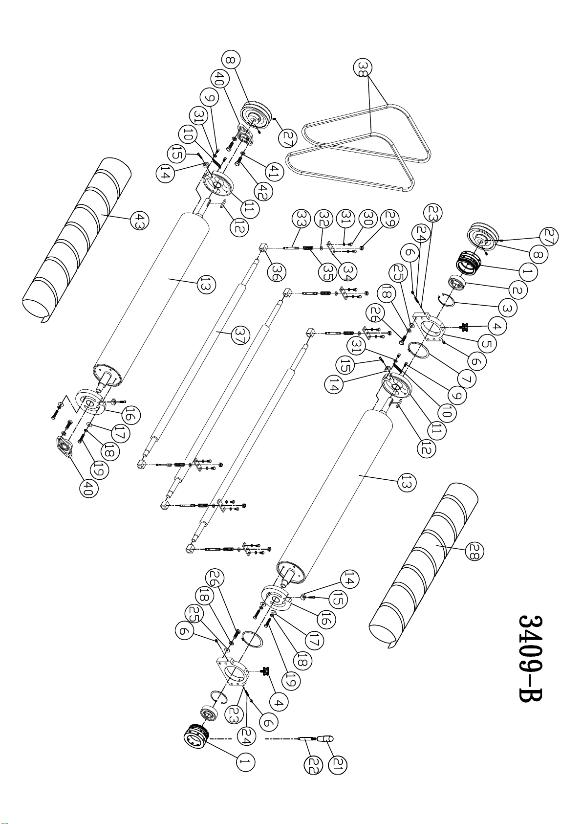
3409 - B DRUM ASSEMBLY
1/6
Page 18
NO. REF.
Part No.
DESCRIPTION Specifiction QTY
3409-B19
19 50151091
Hex. Nut
3/8"-16UNC*1 3/4"L 4
3409-B21
21 34014014
Handle
1
3409-B22
22 34082004
Position handle
1
3409-B23
23 51301003
Steel ball
8mm 2
3409-B24
24 23031055
Spring
2
3409-B25
25
50351065
Flat washer
3/8"*20*3t 8
3409-B26
26 50151097
Hex. nut
3/8"-16UNC*1 1/2"L 8
3409-B27
27 50172003
Set Screw
5/16"-18UNC*1/2"L 4
3409-B28
28 34032011
sanding cloth
100# 1
3409-B29
29 50202012
Nylon nut
M10*1.5P 6
3409-B30
30 50151008
Hex. nut
5/16"-18UNC*5/8"L 12
3409-B31
31 50352003
Spring washer
5/16" 14
3409-B32
32 50301085
Flat washer
10*20*2t 6
3409-B33
33 34062006
lead screw
6
3409-B34
34 34062005
Fix plate
6
3409-B35
35 34062004
Spring
6
3409-B36
36 34022017
Bushing
6
3409-B37
37 34092002
Pressure Roller
3
3409-B38
38 50801012
V-Belt
B-69 2
3409-B40
40 50505002
Bearing
UCFL 205-16(ASAHI) 2
3409-B41
41 50352014
Spring washer
1/2" 4
3409-B42
42 50151087
Hex. Screw
1/2"-13UNC*1 1/2"L 4
3409-B43
43 34032010
Sanding Belt
80# 1
NO. REF.
Part No.
DESCRIPTION Specifiction QTY
3409-C01
1 34083002
Support Bracket, Left-Front
1
3409-C02
2 34073003
Lead screw holder
2
3409-C03
3 50251002
Hex. Nut
1/4"-20UNC 16
3409-C04
4 50151082
Hex. Screw
1/4"-20UNC*1 3/4"L 16
3409-C05
5 50152024
CAP screw
1/4"-20UNC*2 1/4"L 16
3409-C06
6 34023032
Guide plate
2
3409-C07
7 50151088
Hex. screw
1/4"-20UNC*1/2"L 8
3409-C08
8 50352002
Spring washer
1/4" 28
3409-C09
9 34033011
Protecter Lower Bracket
4
3409-C10
10 34073004
Lead screw holder, left-rear
1
3409-C11
11 50351003
Flat washer
1/4"*13*1t 11
3409-C12
12 50151089
Hex. screw
1/4"*20UNC*3/8"L 10
3409-C13
13 34033001
Table
1
3409-C14
14 34083004
Support Bracket, Left-rear
1
3409-C15
15 34033005
Drive roller
1
3409-C16
16 34033006
Rear Support Plate
1
3409-C17
17 34033008
Conveyor Roller Cover-Rear
1
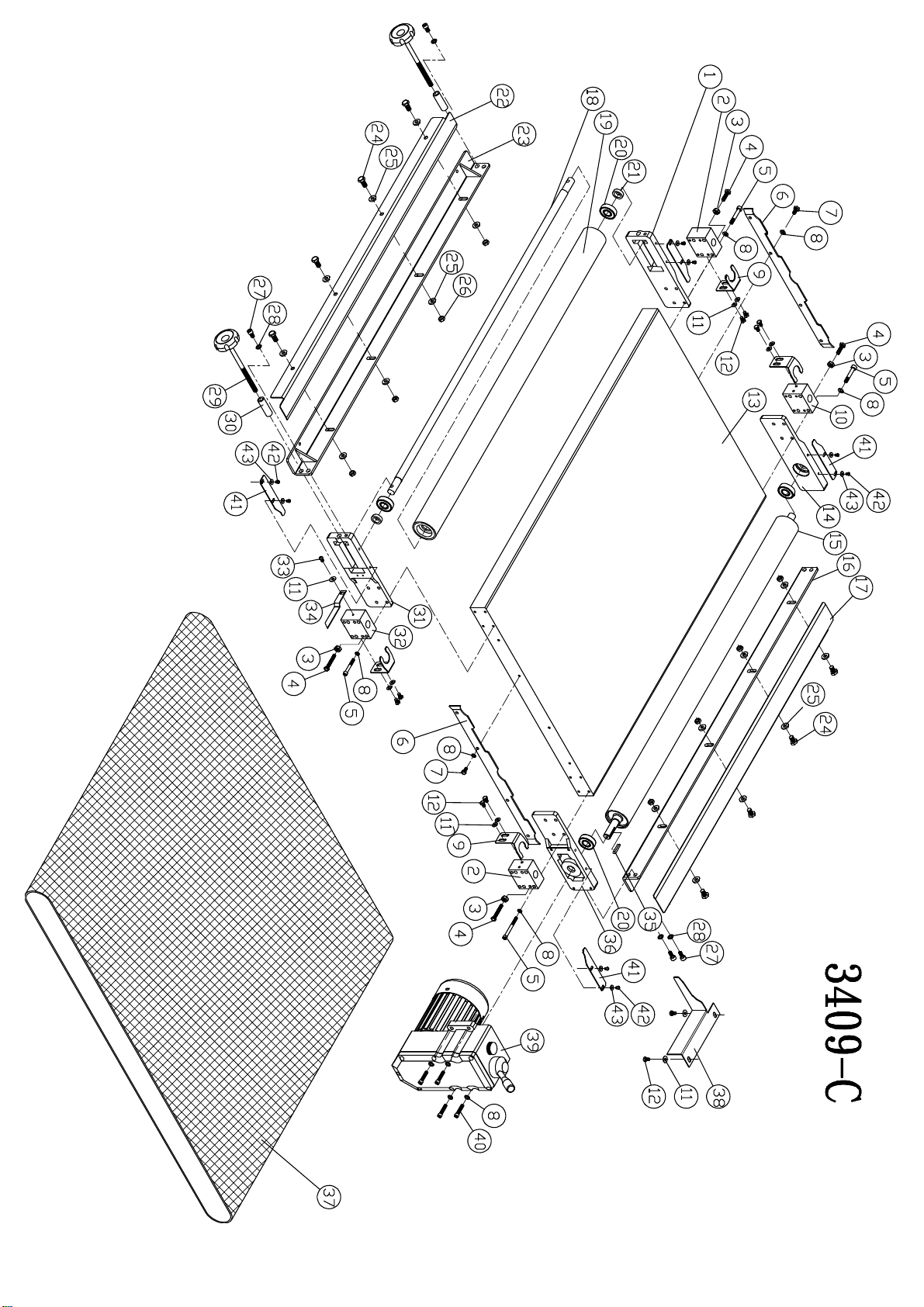
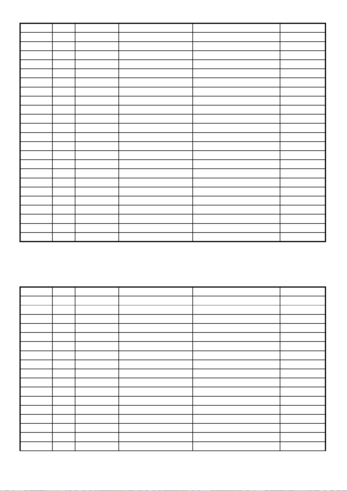
3409 - C TABLE ROLLER ASSEMBLY
2/6
Page 19
NO. REF.
Part No.
DESCRIPTION Specifiction QTY
3409-C18
18 34033002
Conveyor Roller Shaft
1
3409-C19
19 34033003
Conveyor Roller-Front
1
3409-C20
20 50501012
Bearing
6203ZZ 4
3409-C21
21 34013023
Spacer
2
3409-C22
22 34033007
Conveyor Roller Cover-front
1
3409-C23
23 34033004
Conveyor Roller Bracket Link(Front )
1
3409-C24
24 50151010
Hex. screw
5/16"-18UNC*3/4"L 8
3409-C25
25 50351048
Flat washer
5/16"*23*2t 16
3409-C26
26 50251035
Hex. nut
5/16"-18UNC 8
3409-C27
27 50152007
CAP screw
5/16-18UNC*5/8"L 6
3409-C28
28 50352003
Spring washer
5/16" 6
3409-C29
29 50163025
Knob
3/8"-16UNC*150L 2
3409-C30
30 34013011
Spacer
2
3409-C31
31 34083003
Support Bracket, Rightt-Front
1
3409-C32
32 34073002
Lead screw holder, right-front
1
3409-C33
33 50154014
Round head screw
1/4"-20UNC*3/8"L 1
3409-C34
34 34083001
Pointer
1
3409-C35
35 50604017
Key
5*5*30L 1
3409-C36
36 34083005
Support Bracket, Right-rear
1
3409-C37
37 34033009
Conveyor
915W*1830L*4.5t 1
3409-C38
38 34023047
Fix plate
1
3409-C39
39 34024202
Conveyor assembly
1/4HP*400(415)V*50Hz*3PH
1
3409-C40
40
50152005
CAP screw
1/4"-20UNC*1 1/4"L 4
3409-C41 41
34083006
Cover plate
4
3409-C42
42
50154039
Round head screw
3/16"-24UNC*1/4"L 8
3409-C43
43
50351046
Flat washer
3/16"*12*1t 8
NO. REF.
Part No.
DESCRIPTION Specifiction QTY
3409-D1
1
50152018
CAP screw
3/8"-16UNC*3/4"L 6
3409-D2
2
50352004
Spring washer
3/8" 10
3409-D3
3
50351056
Flat washer
3/8"*25*3t 4
3409-D4
4
50154039
Round head screw
3/16"-24UNC*3/8"L 59
3409-D5
5
50351046
flat washer
3/16"*12*1t 56
3409-D6
6 34033010
Protecter Upper Bracket
4
3409-D7
7
50152021
CAP screw
1/4"-20UNC*1/2"L 6
3409-D8
8 50352002
Spring washer
1/4" 19
3409-D9
9
34021019
Spring Plate
2
3409-D10
10
34094013
Support bracket-front
1
3409-D11
11
50154028
Round head screw
1/4"-20UNC*1/4"L 4
3409-D12
12
50101072
Hex. Screw
M8*1.25P*65L 2
3409-D13
13
34031008
EMG.Stop Plate
1
3409-D14
14 50351043
Flat washer
5/16"*18*1.5t 2
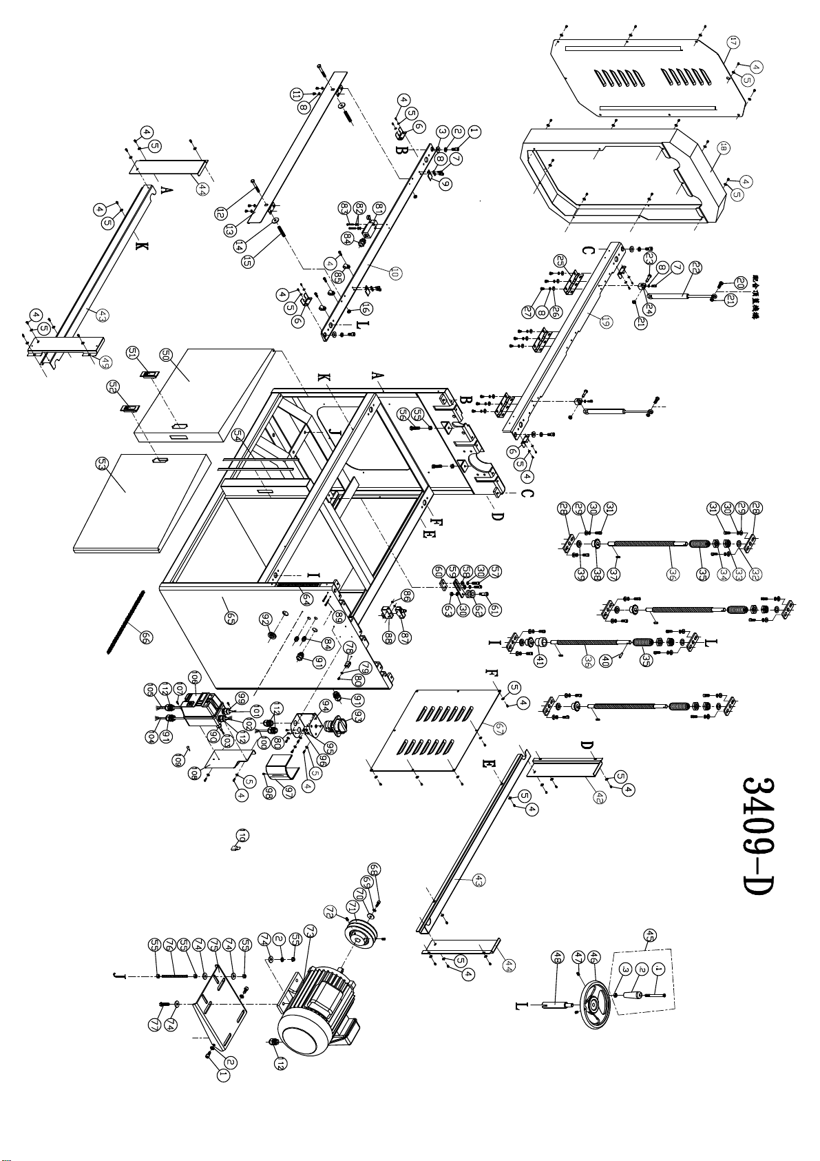
3409 - D CABINET MOTOR ASSEMBLY
3/6
Page 20
NO. REF.
Part No.
DESCRIPTION Specifiction QTY
3409-D15
15
34016002
Spring
2
3409-D16
16
50201019
Hex. Nut
M8*1.25P 2
3409-D17
17
34084009
Belt guard cover
1
3409-D18
18
34084008
Belt guard frame
1
3409-D19
19
34094014
Support bracket-rear
1
3409-D20
20
50102031
CAP screw
M8*1.25P*25L 2
3409-D21
21
50202004
Nylon screw
M8*1.25P 4
3409-D22
22
34031018
Air cylinder
30KG 2
3409-D23
23
34021015
Drive Screw
2
3409-D24
24
34021009
Cylinder Bracket
2
3409-D25
25
34021008
Hinge
3
3409-D26
26 50351003
Flat washer
1/4"*13*1t 9
3409-D27
27 50151088
Hex. screw
1/4"-20UNC*1/2"L 9
3409-D28
28
34013018
Screw bracket
8
3409-D29
29
50351058
Flat washer
5/16"*22*3t 16
3409-D30
30
50352003
Spring washer
5/16" 19
3409-D31
31
50152027
CAP screw
5/16"-18UNC*3/4"L 16
3409-D32
32
34023034
Nylon washer
4
3409-D33
33
34023046
Hex. nut
4
3409-D34
34
34023042
Hex. nut
4
3409-D35
35 34033012
Rubber Protecter
4
3409-D36
36
34023036
Drive Screw
4
3409-D37
37
50604011
Key
5*5*18L 4
3409-D38
38
34013017
Chain Wheel
4
3409-D39
39
50507001
Bearing
NTB1528*1+AS1528*2
4
3409-D40
40
50602045
Spring pin
6*22L 1
3409-D41
41
34023041
position ring
1
3409-D42
42
34084005
Guard-Left rear
1
3409-D43
43
34094004
Chain guard
2
3409-D44
44
34084006
Guaed-left front
2
3409-D45
45 34013101
Hand wheel assembly
1
3409-D45
45.1
34013024
screw
1
3409-D45
45.2
34013021
Handle
1
3409-D45
45.3 50251006
Hex. nut
3/8"-16UNC 1
3409-D46
46
34023021
hand wheel
1
3409-D47
47
50172003
SET screw
5/16"-18UNC*1/2"L 6
3409-D48
48
34023020
Hand wheel Shaft
1
3409-D49
49
34084007
Guard - right front
1
3409-D50
50
34094102
Door assembly -left Front
1
3409-D51
51
23042004
Door hinge - left
1
3409-D52
52
34021036
Door hinge - right
1
3409-D53
53
34094101
Door assembly - right front
1
3409-D54
54
34064009
Sponge
2
3409-D55
55
50251023
Hex. nut
3/8"-16UNC 14
3409-D56
56 50151020
Hex. screw
3/8"-16UNC*1"L 4
3409-D57
57
50152044
CAP screw
5/16"-18UNC*1"L 3
4/6
Page 21
NO. REF.
Part No.
DESCRIPTION Specifiction QTY
3409-D58
58 50351075
Flat washer
5/16"*16*2t 2
3409-D59
59
34021044
Chain Pressure Plate
1
3409-D60
60
34021045
Pad
1
3409-D61
61
34014011
Lock screw
1
3409-D62
62
34011015
Chain Pressure Wheel
1
3409-D63
63
50251035
Hex. nut
5/16"-18UNC 9
3409-D64
64
34064010
Rule
1
3409-D65
65
34094012
Cabinet
1
3409-D66
66
50802003
Chain
#35*352P 1
3409-D67
67
34074002
Back cover
1
3409-D68
68
50102043
Flat washer
M10*1.5P*25L 1
3409-D69
69
50302010
Pulley
M10
1
3409-D70
70
50351053
Flat washer
5/16"*30*3t 1
3409-D71
71
34031009
Pulley
1
3409-D72
72
50153008
Set screw
5/16"-18UNC*1/2"L 2
3409-D73
73
3409450A
Motor
10*8*55L 1
3409-D74
74
50351055
Flat washer
3/8"*28*3t 12
3409-D75
75
34031010
Motor plate
1
3409-D76
76
34011007
adjusting screw
2
3409-D77
77
50151091
Hex. screw
3/8"-16UNC*1 3/4"L 4
3409-D78
78 23011077
Clip
1
3409-D79
79 50352001
Spring washer
3/16" 1
3409-D80
80 50154042
Round head screw
3/16"-24UNC*5/16"L 3
3409-D81
81
34016003
Limit switch
ADS1004 1
3409-D82
82
50352001
Spring washer
3/16" 6
3409-D83
83
50154038
Round head screw
3/16"-24UNC*1 1/4"L 2
3409-D84
84
51104004
Strain Relief
PG 11(CE) 3
3409-D85
85
51110001
Cable Clamp
ACC-2.5 (7.8mm) 3
3409-D86
86
50201011
Hex. nut
M4*0.7P 2
3409-D87
87 51130001
Limit switch
Z15G1307 1
3409-D88
88 51131001
Switch cover
AMC-1L 1
3409-D89
89
50104004
Round head screw
M4*0.7P*30L 2
3409-D90
90 51104022
Strain Relief
PG9(CE) 1
3409-D91
91 51104003
Strain Relief
PG 13.5(CE) 4
3409-D92
92
34011029
Strain Relief
1
3409-D93
93 34021601
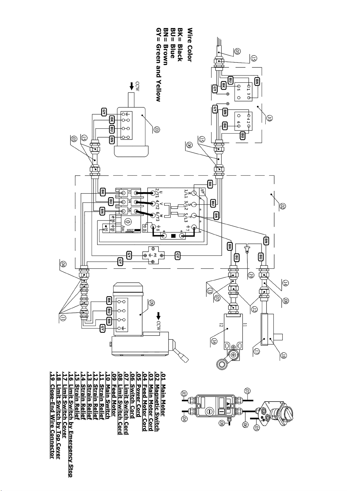
Main switch
ZH-HD-2-48(KEDU) 1
3409-D94
94 34011027
Switch cover
1
3409-D95
95 50251033
Hea. Nut
3/16"-24UNC
2
3409-D96
96
50303003
teeth washer
M5
2
3409-D97
97 34011026
Switch cover, upper
1
3409-D98
98
50104010
Round head screw
M4*0.7P*6L 1
3409-D99
99 51104016
Strain Relief
PG 13.5 1
3409-D100
100
3409480A
Power cord
1
3409-D101
101
3409490B
Limit switch wire
1
3409-D102
102
3409470B
conveyor motor wire
1
3409-D103
103
3409490C
Limit switch wire
1
5/6
Page 22
NO. REF.
Part No.
DESCRIPTION Specifiction QTY
3409-D104
104
3409490A
Switch wire
1
3409-D105
105
3409470A
Motor wire
1
3409-D106
106
3409460A
Magnetic switch
1
3409-D107
107
50104049
Round head screw
M4*0.7P*12L 2
3409-D108
108
34084010
Switch bracket
1
3409-D109
109 51125001
Close-End Wire Connector
CE-1(KSS)
1
3409-D110
110 51706001
Lock
1
3409-D111
111 34021602
Power cord plug
P551
1
3409-D112 112
51104003
Strain Relief
PG 13.5(CE) 5
NO. REF.
Part No.
DESCRIPTION Specifiction QTY
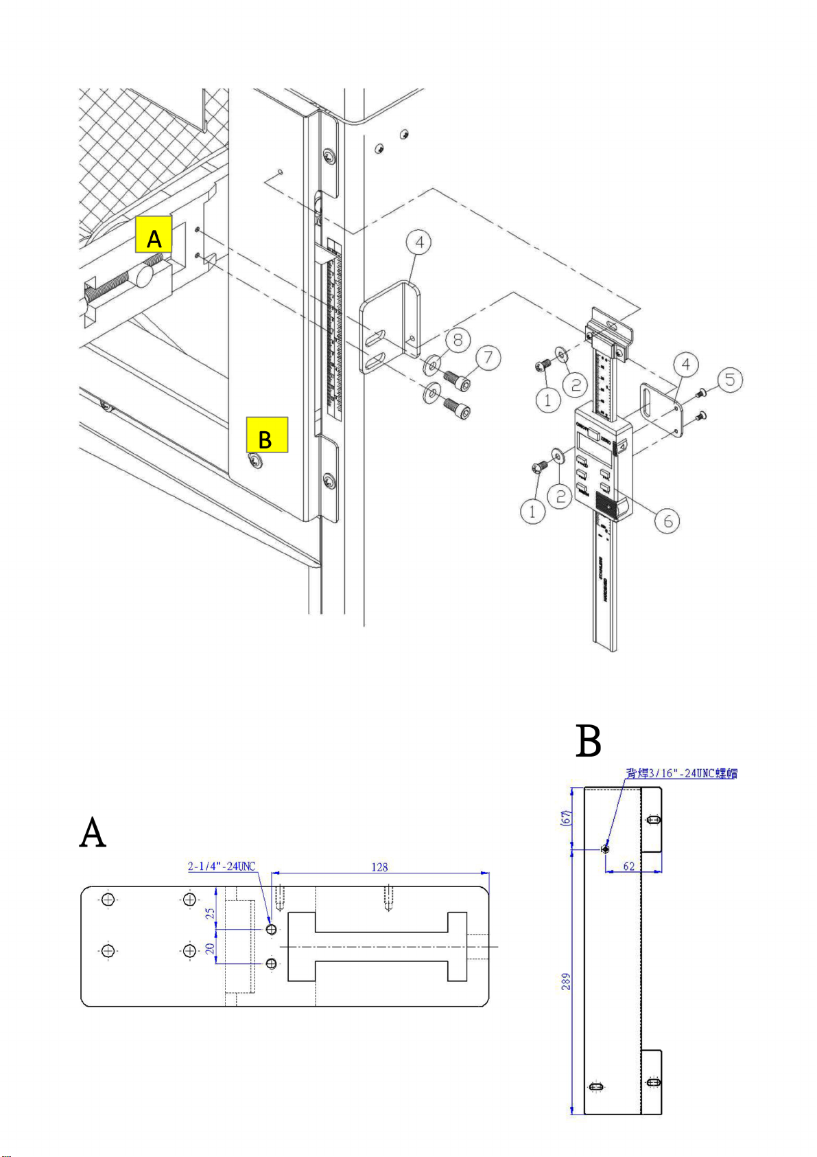
3409-E01
1 50154042
Round head screw
3/16"-24UNC*5/16"L 2
3409-E02
2 50351046
Flat washer
3/16"*12*1t 2
3409-E03
3 34027004
Lower Bracket
1
3409-E04
4 34027003
Bracket
1
3409-E05
5 50105029
Pan head screw
M3*0.5P*5L 2
3409-E06
6 34027001
Readout
1
3409-E07
7 50152021
CAP screw
1/4"-20UNC*1/2"L 2
3409-E08 8
50351050
Flat washer
1/4"*16*2t 2
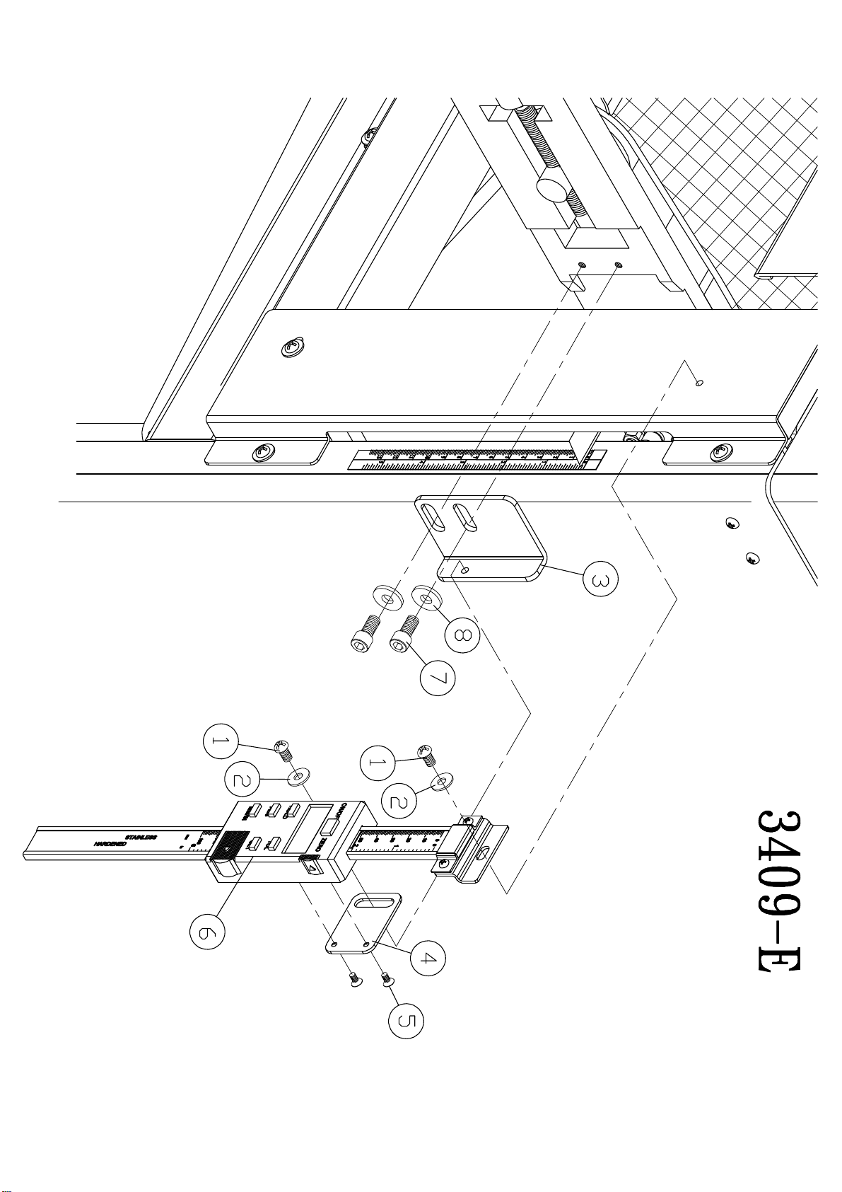
3409 - E DIGITAL READOUT (OPTIONAL)
6/6
Page 23
Page 24

The Axminster guarantee
Buy with confidence from Axminster!
So sure are we of the quality, we cover all parts and labour free of charge for three years!
For more information visit axminstertools.com/3years
The packaging is suitable for recycling.
Please dispose of it in a responsible manner.
EU Countries Only
Do not dispose of electric tools together with household waste material.
By law they must be collected and recycled separately.
Axminster Tools, Axminster Devon EX13 5PH
axminstertools.com
 Loading...