

Page 1
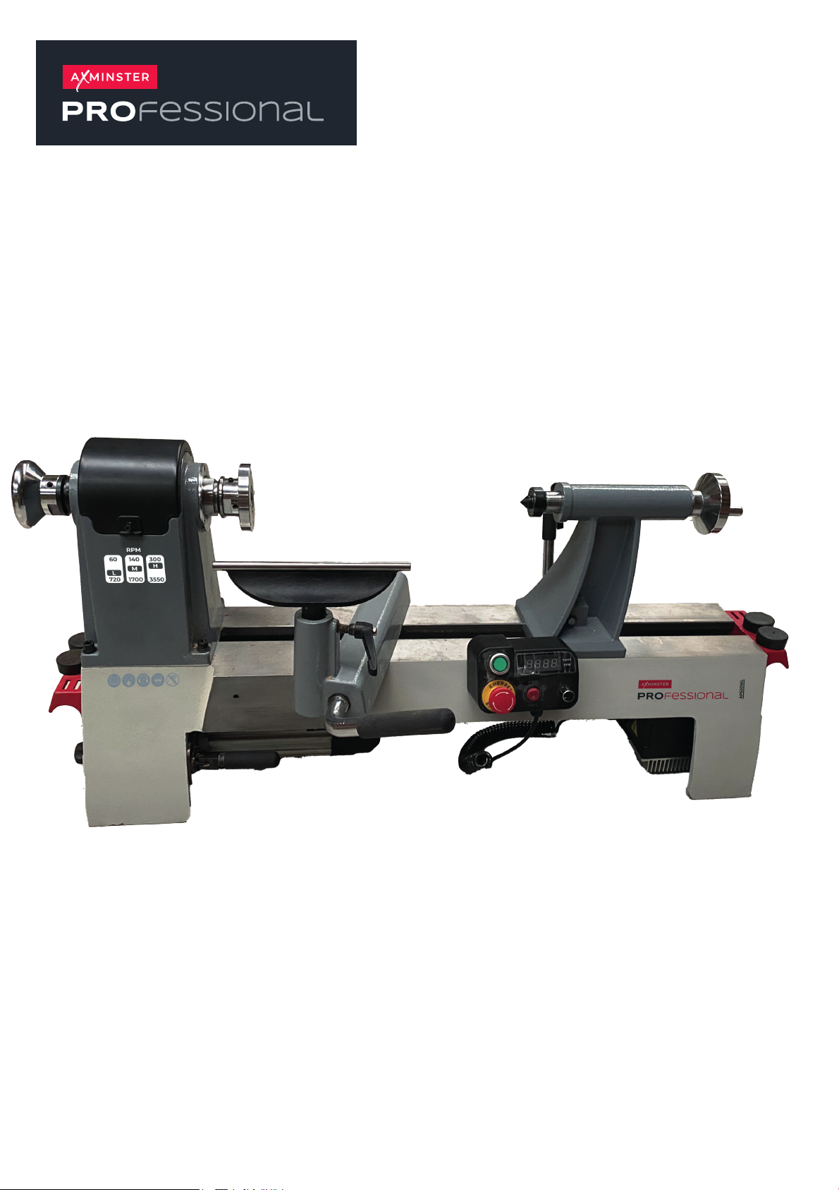
AP530WL Bench
Lathe 230V
Code 111887
Original Instructions
AT: 17/11/2024
BOOK VERSION: 1
Page 2

Table of contents
1. Safety …………………………………………………………………………………………………………………..1
1.1 Safety instructions for general machinery .................................................................................................. 1
1.2 Intended use .............................................................................................................................................. 2
1.3 Safety instructions for wood turning lathe .................................................................................................. 3
1.4 Safety devices ............................................................................................................................................ 4
1.5 Reasonably foreseeable misuse ................................................................................................................ 4
1.6 Possible dangers caused by the wood turning lathe. ................................................................................. 4
1.7 Safety check .............................................................................................................................................. 5
1.8 Safety during operation .............................................................................................................................. 5
2. Technical Specification ................................................................................................................................. 6
2.1 Specification .............................................................................................................................................. 6
2.2 Dimensions ................................................................................................................................................ 6
3. Assembly ........................................................................................................................................................ 7
3.1 Needed for Setup ...................................................................................................................................... 7
3.2 Unpacking the machine ............................................................................................................................. 7
3.3 Cleanup ..................................................................................................................................................... 7
3.4 Placement location .................................................................................................................................... 8
3.5 Assembly ................................................................................................................................................... 8
3.6 Initial commissioning .................................................................................................................................. 9
3.7 Adjustment ................................................................................................................................................. 9
3.7.1 Tool rest adjustment ........................................................................................................................... 9
3.7.2 Setting up the face plate ................................................................................................................... 10
3.7.3 Setting up the headstock spur center ............................................................................................... 10
3.7.4 Tailstock adjustment ......................................................................................................................... 11
3.7.5 Setting up the tailstock live center .................................................................................................... 11
3.7.6 Indexing/Spindle lock ........................................................................................................................ 11
3.7.7 Adjusting the speed .......................................................................................................................... 11
3.7.8 Speed recommendations .................................................................................................................. 13
4. Operation ...................................................................................................................................................... 13
4.1 Spindle turning ......................................................................................................................................... 13
4.1.1 Spindle turning tips ........................................................................................................................... 14
4.1.2 Roughing out cut .............................................................................................................................. 15
4.1.3 Creating Beads ................................................................................................................................. 15
4.1.4 Creating coves .................................................................................................................................. 16
4.1.5 Creating V-grooves ........................................................................................................................... 16
4.1.6 Sanding the workpiece ..................................................................................................................... 16
4.2 Bowl turning ............................................................................................................................................. 16
4.2.1 Mounting the workpiece onto the face plate ..................................................................................... 16
4.2.2 To shape the inside of a bowl or plate .............................................................................................. 17
Page 3

4.3 T urning tools ............................................................................................................................................ 17
5. Maintenance ................................................................................................................................................. 19
5.1 Schedule .................................................................................................................................................. 19
5.2 Cleaning .................................................................................................................................................. 19
5.3 Lubrication ............................................................................................................................................... 19
5.4 Tensioning and replacing belt .................................................................................................................. 20
5.4.1 Tension belt ...................................................................................................................................... 20
5.4.2 Replacing belt ................................................................................................................................... 20
5.5 Replacing brushes (FOR MC1421VDA ONLY) ....................................................................................... 20
6. Troubleshooting .......................................................................................................................................... 22
6.1 Motor& Electrical ..................................................................................................................................... 22
6.2 Wood lathe operations ............................................................................................................................. 23
7.Optional accessories ................................................................................................................................... 24
7.1 New extension bed .................................................................................................................................. 24
7.1.1 Dimensions ....................................................................................................................................... 25
Diagram and part list .................................................................................................................................... 25
8.
8.3 Diagram for MC1421VDB ........................................................................................................................ 25
8.4 Part list for MC1421VDB .......................................................................................................................... 26
8.8 Wiring diagram for MC1421VDB ............................................................................................................. 27
Page 4

1. Safety
This operating instructions
▲explains the meaning and use of the warning notes included in the operating instructions
▲points out the dangers that might arise for you or others if these instructions are not
observed.
▲informs you how to avoid dangers.
In addition to these operation instructions, please observe
▲the applicable laws and regulations
▲the statutory provisions for accident prevention
▲the prohibition, warning and mandatory signs as well as the warning notes on the machine.
If required, the relevant measures to comply with the country-specific regulations must be taken
before commissioning the machine.
Always keep this documentation close to the wood turning lathe.
1.1 Safety instructions for general machinery
The purpose of safety symbols is to attract your attention to possible hazardous conditions. This
manual uses a series of symbols and signal words intended to convey the level of importance of the
safety messages. The progression of symbols is described below. Remember that safety messages
by themselves do not eliminate danger and are not a substitute for proper accident prevention
measures.
WARNING
Some dust created by power sanding, sawing, grinding, drilling, and other construction activities
may contain chemicals, including lead, birth defects, or other reproductive harm. Wash hands after
handling. Some examples of these chemicals are:
• Lead from lead-based paints.
• Crystalline silica from bricks, cement, and other masonry products.
• Arsenic and chromium from chemically treated lumber.
Your risk from these exposures varies depending on how often you do this type of work. To reduce
your exposure to these chemicals, work in a well-ventilated area with approved safety equipment
such as dust masks specially designed to filter out microscopic particles.
1
Page 5

protective suit
safety shoes
protective gloves
protective glasses
For your own safety, read instruction manual before operating the machine. Learn
the machine’s application and limitations as well as the specific hazards peculiar.
Always wear approved safety glasses or a face shield when operating or observing
machinery to reduce the risk of eye injury or blindness from flying particles Everyday
eyeglasses are not approved safety glasses.
Dust created while using machinery may cause cancer, birth defects, or long-term
respiratory damage. Be aware of dust hazards associated with each workpiece
material, and always wear an approved respirator to reduce your risk.
Always wear hearing protection when operating or observing loud machinery.
Extended exposure to this noise without hearing protection can cause permanent
hearing loss.
Keep hands and clothing away from moving parts. Always tie back or cover long hair.
Wear non-slip footwear to avoid accidental slips which could cause a loss of
workpiece control.
1.11 Personal protective equipment
Dirty or contaminated personal protective equipment can cause illness. Clean your
personal protective equipment after each use and once a week.
1.2 Intended use
The wood turning lathe is designed and manufactured for use in non-explosive environments.
The wood turning lathe is designed and manufactured to cast material and plastics or other material
that are not hazardous to health and do not generate dust.
The wood turning lathe must only be installed and operated in dry and ventilated areas.
2
Page 6

1.3 Safety instructions for wood turning lathe
Verify each
workpiece is free of knots, splits, nails, or foreign
Before mounting, cut off waste portions to balance workpiece for
Verify tool rest, headstock, and tailstock are secure before turning
Firmly hold turning tool with both hands against tool rest.
started.
you can verify safe rotation.
Select correct spindle speed for workpiece size, type, shape, and
Serious injury or death can occur from getting entangled in, crushed between, or
struck by rotating parts on a lathe! Rotating workpieces can come loose and strike
operator or bystanders with deadly force if they are improperly secured, rotated too
fast, or are not strong enough for the rotational forces required for turning. Improper tool setup
or usage can cause tool kickback or grabbing, resulting in impact injury or entanglement. To
reduce the risk of operator (or bystander) injury or death, anyone operating this machine MUST
completely heed the hazards and warnings below.
VERIFY WORKPIECE
INTEGRITY
PROPERLY PREPARE
WORKPIECE
SECURE LOCKS
SECURE WORKPIECE
ADJUST TOOL SUPPORT
material to ensure it can safely rotate on spindle without breaking
apart or causing tool kickback.
safe rotation and removal of large edges that can catch on tooling.
lathe ON.
Use proven setup techniques and always verify workpiece is wellsecured before starting lathe.
Only use high-quality fasteners with non-tapered heads for
faceplate attachment.
An improperly sup-ported tool may be grabbed or ejected.
Adjust tool rest approximately 1⁄4" away from workpiece and 1⁄8"
above workpiece center line to provide proper support for turning
tool.
REMOVE ADJUSTMENT
TOOLS
Remove all chuck keys, wrenches, and adjustment tools before
turning lathe ON.
These items can become deadly projectiles when spindle is
CHECK CLEARANCES
Before starting spindle, verify workpiece has adequate clearance
by hand-rotating it through its entire range of motion.
TEST NEW SETUPS
Test each new setup by starting spindle rotation at lowest speed
and standing to side of lathe until workpiece reaches full speed and
WEAR PROPER PPE
Always wear a face shield and safety glasses when operating
lathe.
Do not wear gloves, necktie or loose clothing. Keep long hair away
from rotating spindle.
USE CORRECT SPEEDS
condition.
Use low speeds when roughing or when turning large, long, or nonconcentric workpieces.
Allow spindle to reach full speed before turning.
AVOID TOOL KICKBACK
This occurs when turning tool is grabbed or ejected from workpiece
with great force.
3
Page 7

SAFELY PERFORM
ROUGHING
tool with both hands.
increases the risk of tool kickback or grabbing
To reduce entanglement risk, remove tool rest before sanding.
Commonly caused by poor workpiece selection/preparation,
improper tool usage, or improper machine setup or tool rest
adjustment.
Use correct tool. Take light cuts, use low speeds, and firmly support
USE SHARP TOOLS
SAFELY STOPPING
ROTAT ION
SAFELY MEASURE
WORKPIECE
Sharp tools cut with less resistance than dull tools. Using dull tools
Always allow rotating workpiece to stop on its own.
Never put hands or another object on workpiece to stop it.
Only measure mounted workpiece after it has completely stopped.
Trying to measure a spinning workpiece increases entanglement
risk.
SANDING/POLISHING
Never completely wrap sandpaper around workpiece.
No list of safety guidelines can be complete. Every shop environment is different. Accidents
are frequently caused by lack of familiarity or failure to pay attention. Use this machine
with respect and caution to lessen the possibility of operator injury. If normal safety
precautions are overlooked or ignored, serious personal injury may occur.
1.4 Safety devices
The wood turning lathe must only be used with fully functional safety devices.
Stop the machine immediately if a safety device is defective or becomes ineffective. This is your
responsibility!
If a safety device has been activated or has failed, the machine must only be used if you have
eliminated the cause of the fault and have verified that there is no danger to personnel or objects.
The wood lathe features the following safety devices:
▲a protective cover for the V-belts ▲Whole switch box cover underneath the wood lathe.
1.5 Reasonably foreseeable misuse
Any use other than that specified under "Intended use" or any use beyond the described use will be
deemed non-intended use and is not permissible. Any other use must be discussed with the
manufacturer.
In order to avoid misuse, the operating instructions must be read and understood before first
commissioning. The operator of the wood lathe must be duly qualified.
1.51 Avoiding misuse
▲ Correct belt speed for rotating the workpiece.
▲ Use the correct chisels, depending on the workpiece’s material.
▲ Clamp the workpiece firmly by wood chucks etc.
1.6 Possible dangers caused by the wood turning lathe.
The wood turning lathe has undergone a safety inspection (hazard analysis with risk assessment).
It has been designed and built on the basis of this analysis. Anyway, there is a residual risk as the
4
Page 8

machine operates under electrical voltage and currents and high speed.
We have used design and safety engineering to minimize the health risk to personnel resulting from
these hazards. If the machine is used and maintained by personnel who are not duly qualified, there
may be a risk resulting from incorrect or unsuitable maintenance.
This manual uses a series of symbols and signal words intended to convey the level of importance of
the safety messages.
Remember that safety messages by themselves do not eliminate danger and are not a substitute for
proper accident prevention measures.
1.7 Safety check
Check all safety devices when starting any task, once a week and after any maintenance and repair
work. Close all protective covers before starting the wood turning lathe.
1.8 Safety during operation
We specifically point out the dangers in the description of work with and on the wood turning lathe.
Avoid any unsafe work methods:
▲ Make sure that your operation does not create a safety hazard.
▲ The rules specified in these operating instructions must be observed during assembly, operation,
maintenance and repair.
▲ Do not work on the machine if your concentration is reduced, for example because you are
taking medication.
▲ Stay with the machine until all movements have come to a complete standstill.
▲ Use the specified personal protective equipment. Ensure you wear well-fitting clothing and, if
necessary, a hairnet.
1.8.1 Disconnecting and securing the wood turning lathe
Pull out the power plug before beginning any maintenance or repair. All machine parts as well as all
dangerous voltages must be switched off.
Live parts and movements of machine parts can cause severe injury to yourself and
others! Proceed with extreme caution, if the mains plug of the wood turning lathe cannot
be disconnected due to the nature of the required work (e.g. functional check).
1.8.2 Using lifting equipment
The use of unstable lifting and load suspension equipment that might break under load
can cause severe injuries or even death. Check that the lifting and load suspension
equipment are of sufficient load-bearing capability and are in perfect condition. Fasten
loads carefully. Never walk under suspended loads!
5
Page 9
2. Technical Specification
The following information represents the dimensions and weight information and the
manufacturer‘s approved machine data.
2.1 Specification
Model Number AP530WL
Motor Power 1100W/1400W
DC brushless motor
60-720
Spindle RPM/50Hz
Spindle Thread M33X3.5 or other
Spindle /Tailstock Taper MT2
No. of Indexes 24
Tailstock Quill Travel 4”(100mm)
Swing Over Bed 14.5”
Swing Over Tool Rest Base 10.55”
Distance Between Centers 21”
Faceplate Diameter 3”
Tool rest Width 8”
Packing size(mm) 970X525X300
Net/Gross Weight (kgs) 56.5/59
130-1700
300-3550
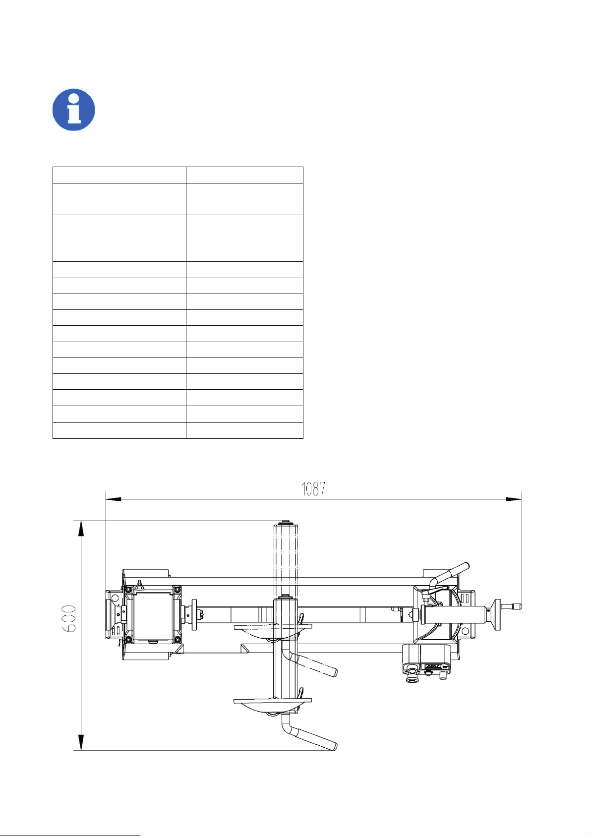
2.2 Dimensions
6
Page 10

3. Assembly
The wood turning lathe is delivered pre-assembled. After unpacking, the lathe must be
installed.
Transport the wood turning lathe in its packing crate to a place near its final installation
site before unpacking it. If the packaging shows signs of possible transport damage, take
the necessary precautions not to damage the machine when unpacking. If any damage
is discovered, the carrier and/or shipper must be notified of this fact immediately to
establish any claim which might arise.
3.1 Needed for Setup
This machine is heavy. DO NOT over-exert yourself while unpacking or moving
machine—get assistance!!
3.2 Unpacking the machine
Inspect the machine completely and carefully, making sure that all materials, such as shipping
documents, instructions and accessories supplied with the machine have been received.
The following is a list of items shipped with your machine. Before beginning setup, lay these items out
and inventory them.
A. Knockout Rod........................................ 1
B. Open-End Wrench 41mm.......................2
C. Hex Wrenches 3, 4, 5mm.......................1
D. Live Center MT#2...................................1
E. Spur Center MT#2..................................1
F. Power Cord.............................................1
G. Rubber Feet M8-1.25 x 15.................... 4
If you cannot find an item on this list, carefully check around/inside the machine
and packaging materials. Often, these items get lost in packaging materials while
unpacking or they are pre-installed at the factory.
3.3 Cleanup
The unpainted surfaces of the machine are coated with a heavy-duty rust preventative that prevents
corrosion during shipment and storage.
This rust preventative works extremely well, but it will take a little time to clean.
Be patient and do a thorough job cleaning your machine. The time you spend doing this now will
7
Page 11
give you a better appreciation for the proper care of your machine's unpainted surfaces.
Basic steps for removing rust preventative:
1. Put on safety glasses.
2. Coat the rust preventative with a liberal amount of cleaner/degreaser, then let it soak for 5–10
minutes.
3. Wipe off the surfaces. If your cleaner/degreaser is effective, the rust preventative will wipe off
easily. If you have a plastic paint scraper, scrape off as much as you can first, then wipe off the rest
with the rag.
4. Repeat Steps 2–3 as necessary until clean, then coat all unpainted surfaces with a quality metal
protectant to prevent rust.
Avoid chlorine-based solvents, such as acetone or brake parts cleaner, that may
damage painted surfaces.
3.4 Placement location
Workbench Load
Refer to the Machine Data Sheet for the weight and footprint specifications of your machine.
Some workbenches may require additional reinforcement to support the weight of the machine and
workpiece materials.
3.5 Assembly
The machine must be fully assembled before it can be operated. Before beginning the assembly
process, refer to Needed for Setup and gather all listed items. To ensure the assembly process goes
smoothly, first clean any parts that are covered or coated in heavy-duty rust preventative (if applicable).
To assemble machine
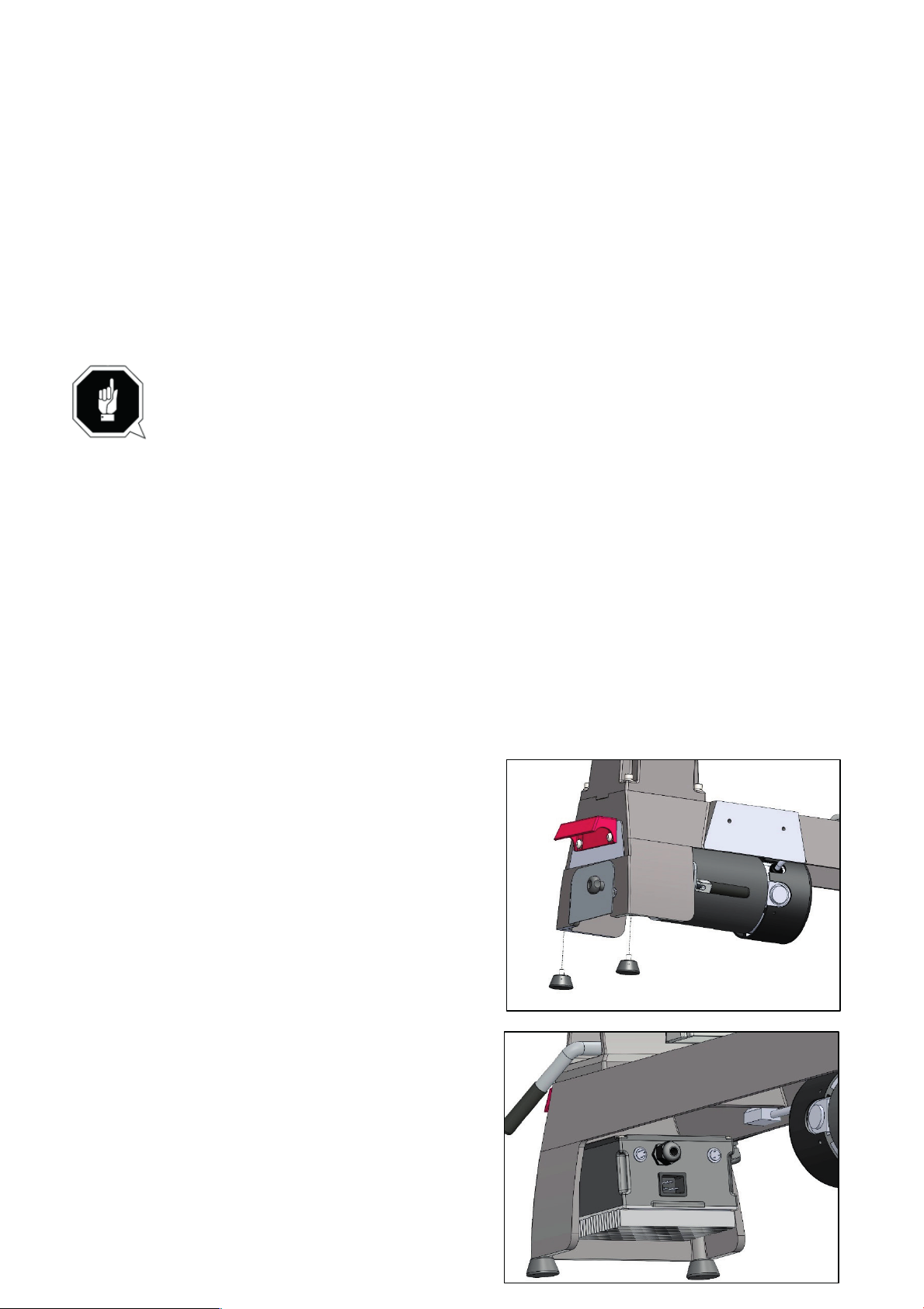
1. Install (4) rubber feet into holes in bottom of legs
and adjust feet so lathe sits level without rocking.
2. Insert end of power cord into receptacle in back of
control box.
8
Page 12
3.6 Initial commissioning
Once assembly is complete, test run the machine to ensure it is properly connected to power and
safety components are functioning correctly. If you find an unusual problem during the test run,
immediately stop the machine, disconnect it from power, and fix the problem BEFORE operating the
machine again.
The test run consists of verifying the motor powers up and runs correctly.
To test run machine:
1. Clear all setup tools away from machine.
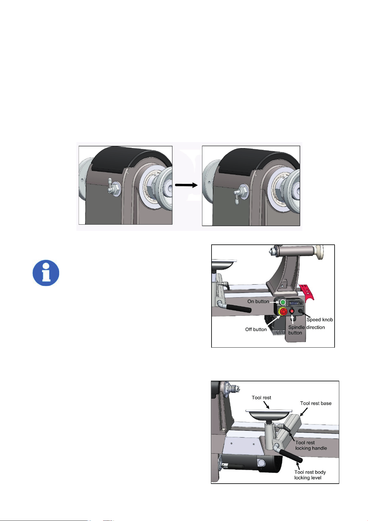
2. Open the indexing pin knob and rotate so detent is seated on roll pin. This disables the indexing
pin knob.
3. Turn spindle speed knob all the way counterclockwise.
4. Connect machine to power supply.
Verify machine is operating correctly
by setting spindle direction switch in
forward position, pressing ON button,
then slowly turning spindle speed dial
clockwise. The digital readout should illuminate,
and spindle should rotate down toward front of
lathe.
5. Turn spindle speed dial all the way counterclockwise.
6. Press OFF button.
7. Set spindle direction switch to reverse position, press
ON button, then slowly turn spindle speed dial clockwise.
8. When operating correctly, machine runs smoothly with little or no vibration or rubbing noises.
Spindle should rotate up toward rear of lathe.
9. Press OFF button.
3.7 Adjustment
3.7.1 Tool rest adjustment
You can adjust the position, height and angle of the
tool rest assembly to suit your task at hand.
1. The tool rest locking lever (locks the tool rest body) in
position. Loosen the lever to slide the tool rest body along
the lathe bed. Tighten the lever firmly when the tool rest
9
Page 13
body is properly positioned.
NOTE: There is a nut on the underside of tool rest body that needs to be tightened periodically
to enable the tool rest body locking lever to tighten properly.
2. The small tool rest locking handle locks the tool rest in place. Loosen the handle to position the tool
rest at the specific angle or height. Tighten the handle firmly when the tool rest is properly positioned.
3.7.2 Setting up the face plate
NOTE: When installing the face plate for turning bowls and plates, mount the workpiece onto the face
plate prior to installing the face plate on the headstock.
To install the face plate:
1. Thread the face plate onto the headstock spindle by turning it clockwise as far as it will go, and
then tighten the two set screws with a hex wrench.
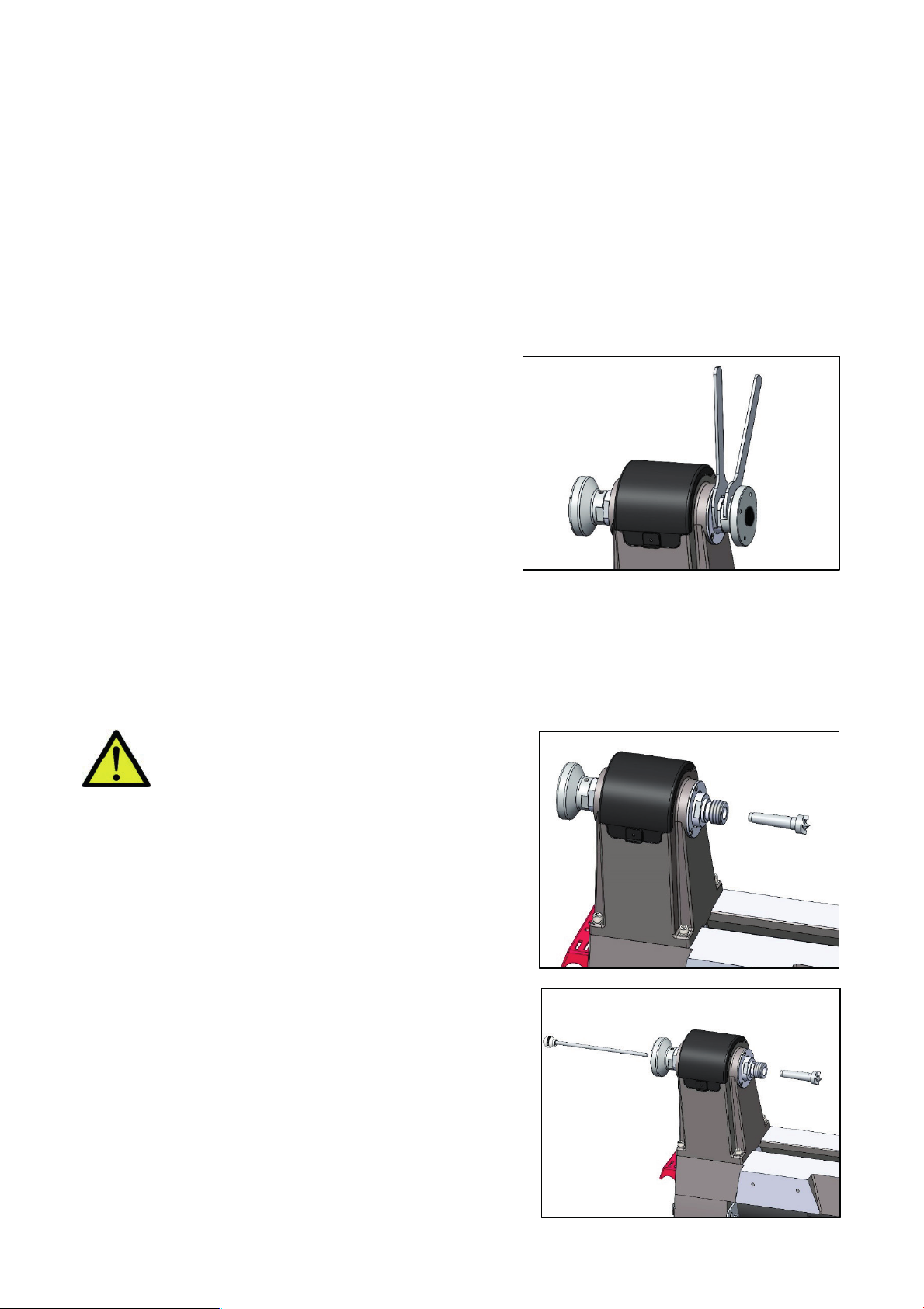
2. Lock the spindle lock by engaging the knob in the deep
groove. Insert the knockout rod into a hole on the side of
the face plate and use the wrench to fully tighten the face
plate.
To remove the face plate:
1. Loosen the two face plate set screws.
2. Lock the spindle lock and use the two wrenches to
unscrew the face plate by turning it towards the operator.
3.7.3 Setting up the headstock spur center
To install the spur center:
1. Make sure the mating surfaces of both the spur center and the headstock spindle are clean. You
can use an acetone-moistened cloth to remove any other debris, oil, etc.
2. Drive the spur center into the workpiece, using a rubber mallet or a piece of scrap wood.
CAUTION: Never drive the workpiece into
the spur center while the spur center is in
the headstock.
3. Push the spur center into the headstock spindle.
To remove the spur center:
1. Hold the spur center to prevent it from falling. Use a rag
to protect your hand from the sharp edges.
2. Insert the knockout rod through the spindle hole to tap
out the spur center.
10
Page 14
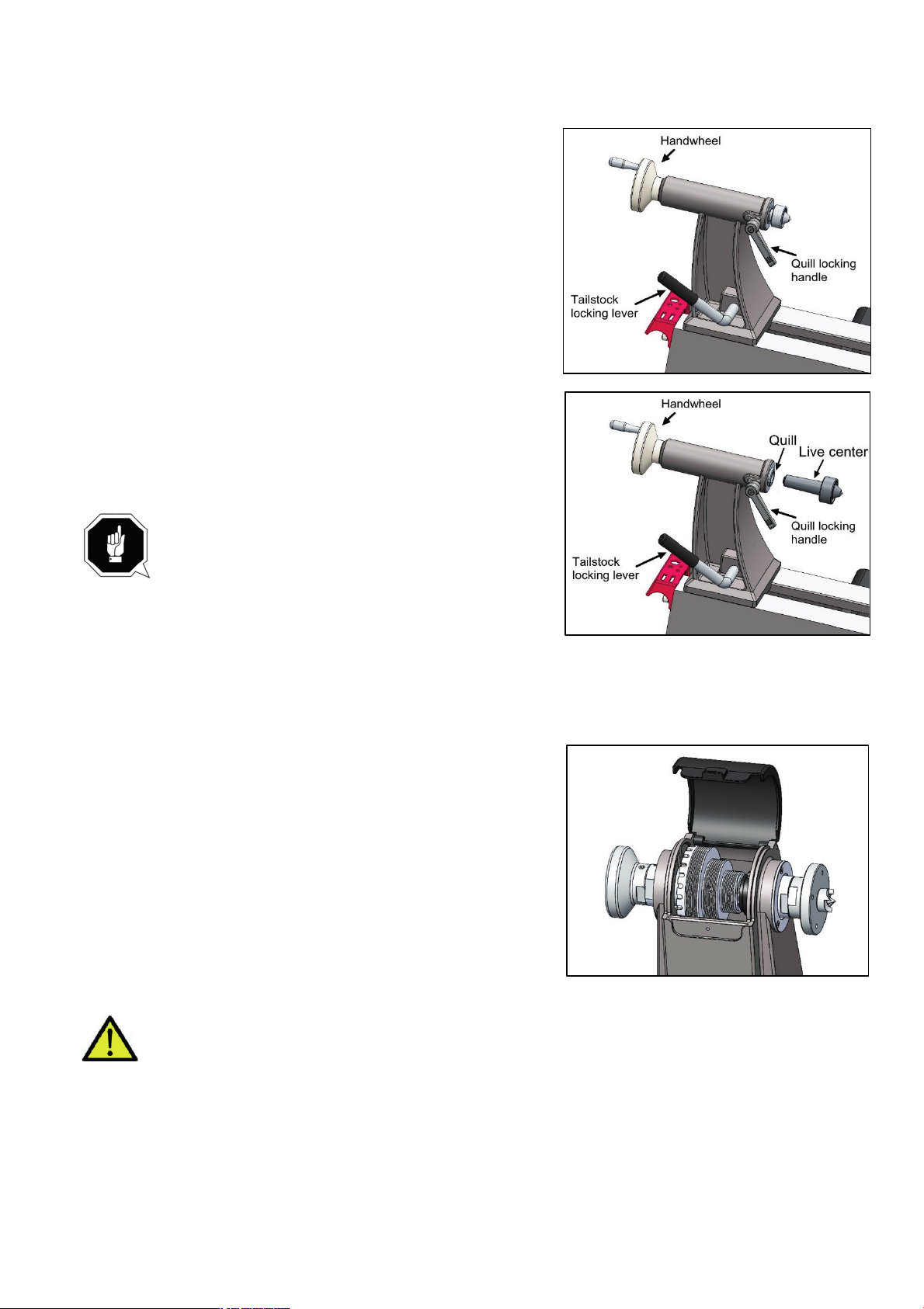
3.7.4 Tailstock adjustment
Loosen the tailstock locking lever and slide the tailstock
along the lathe bed into the desired position. Retighten the
locking lever.
Loosen the quill locking handle just enough to unlock the
tailstock quill. Turn the handwheel clockwise to advance the
quill and counterclockwise to retract the quill. Retighten the
quill locking handle.
3.7.5 Setting up the tailstock live center
To install the live center:
1. Rotate the tailstock handwheel clockwise a few times to
advance the quill forward.
2. Make sure the mating surfaces are clean. Push the live
center into the quill.
NOTE: If the tailstock quill gets fully retracted
when the live center is mounted, it will dismount
the live center. This is normal. Remount the live
center by extending the tailstock quill approximately 0.5 inch
and pushing the live center in place.
To remove the live center:
1. Hold the live center to prevent it from falling. Use a rag to protect your hand from the sharp
edges.
2. Rotate the handwheel counterclockwise to retract the quill
until the live center is released from the quill.
3.7.6 Indexing/Spindle lock
Indexing is used to create evenly spaced features around the
circumference of the workpiece while keeping the spindle
locked. There are 24 index positions in the spindle pulley,
each 15° apart, to help you rotate the workpiece evenly for
accurately spaced features.
Place the spindle lock in the locked position to help maintain the certain index point.
CAUTION: Make sure to DISENGAGE the spindle lock before starting the lathe again.
Never start the lathe with the index pin engaged in the spindle pulley!!
3.7.7 Adjusting the speed
MC1421VDA MC1421VDB: Three speed ranges: 60-720, 130-1700 RPM, and 300-3550 RPM.
MC1421VF: Two speed ranges: Low 0-1500 RPM and High 0-3550 RPM.
11
Page 15
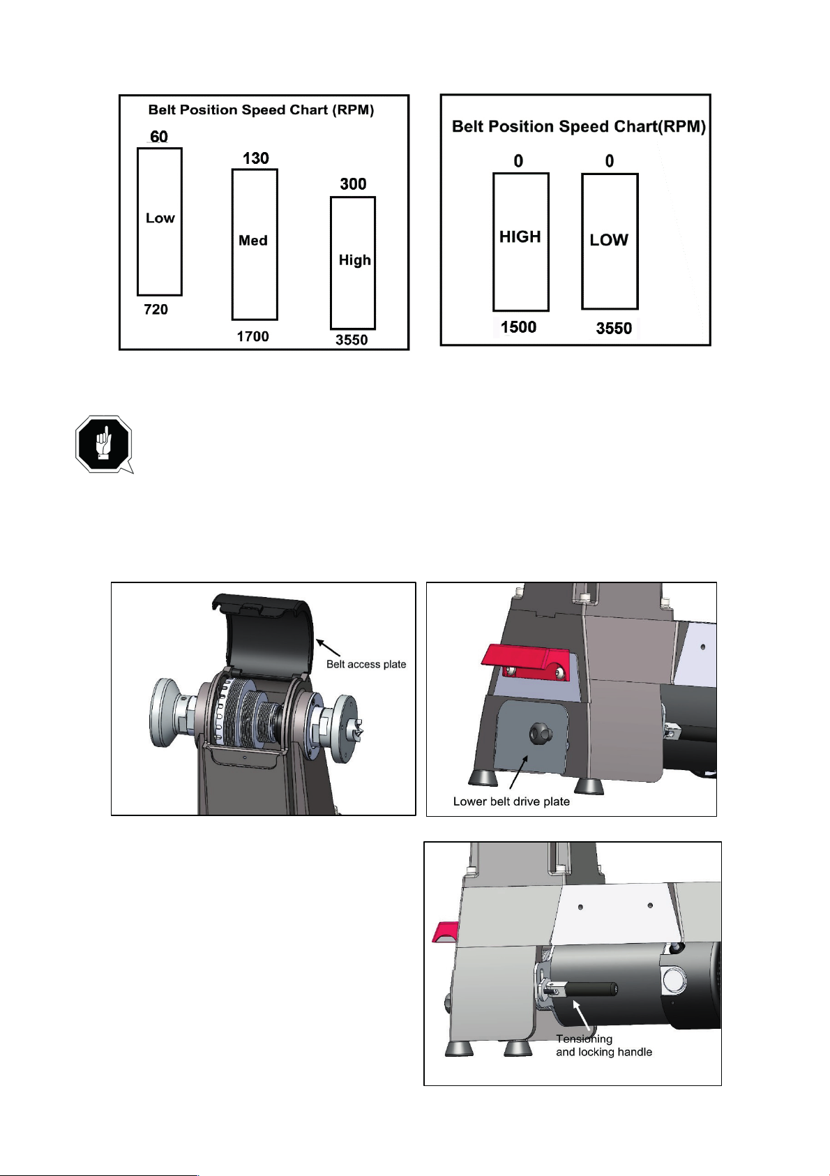
FOR MC1421VDA MC1421VDB FOR MC1421VF
Always start at slower speeds for rough cuts and larger workpieces. Use faster
speeds for refined cuts and detailed work. Set the suitable speed range for your
operation by adjusting the belt position. Change the speed within a speed range
using the speed adjustment knob. The speed will be displayed on the digital RPM
readout on the front panel.
1. When changing speed, make sure to turn off and disconnect the lathe.
2. Loosen the knob on the top front of the headstock and open the belt drive access plate.
3. Open lower belt drive plate onto the left side of the headstock.
4. Loosen the motor tensioning locking handle.
5. Adjust the belt’s position on both the upper
and lower drive pulleys to the desired speed
range setting. Make sure the belt is vertically
aligned on the upper and lower pulleys.
6. Tighten the locking handle to its original
position, allowing the weight of the motor to place
the belt under tension.
8. Close the lower belt drive plate. Close the
upper belt drive access plate and tighten the belt
drive access panel knob.
9. Use the speed adjustment knob on the front
12
Page 16

panel to set the speed within your selected speed range. Use the forward/reverse switch to set the
rotational direction.
3.7.8 Speed recommendations
High range is best when turning a workpiece where a clean finish is required and only light cuts are
made. Mid range is a compromise between high and low ranges. Low range, which has more torque,
is best when turning a workpiece where a lot of material must be removed and a rough finish does
not matter. Use the speed dial to adjust spindle speed within each range.
4. Operation
The purpose of this overview is to provide the novice machine operator with a basic understanding
of how the machine is used during operation, so the machine controls/components discussed later
in this manual are easier to understand. Due to the generic nature of this overview, it is not intended
to be an instructional guide. To learn more about specific operations, read this entire manual, seek
additional training from experienced machine operators, and do additional research outside of this
manual by reading "how-to" books, trade magazines, or websites.
If you are not experienced with this type of machine, WE STRONGLY
RECOMMEND that you seek additional training outside of this manual. Read
books/magazines or get formal training before beginning any projects.
TURN OFF MACHINE BEFORE CHANGING ROTATIONAL DIRECTION.
4.1 Spindle turning
Spindle turning is the operation performed when a workpiece is mounted between centers. Bowls,
table legs, tool handles, and candlesticks are typical projects where this operation is used.
To set up a spindle turning operation:
13
Page 17
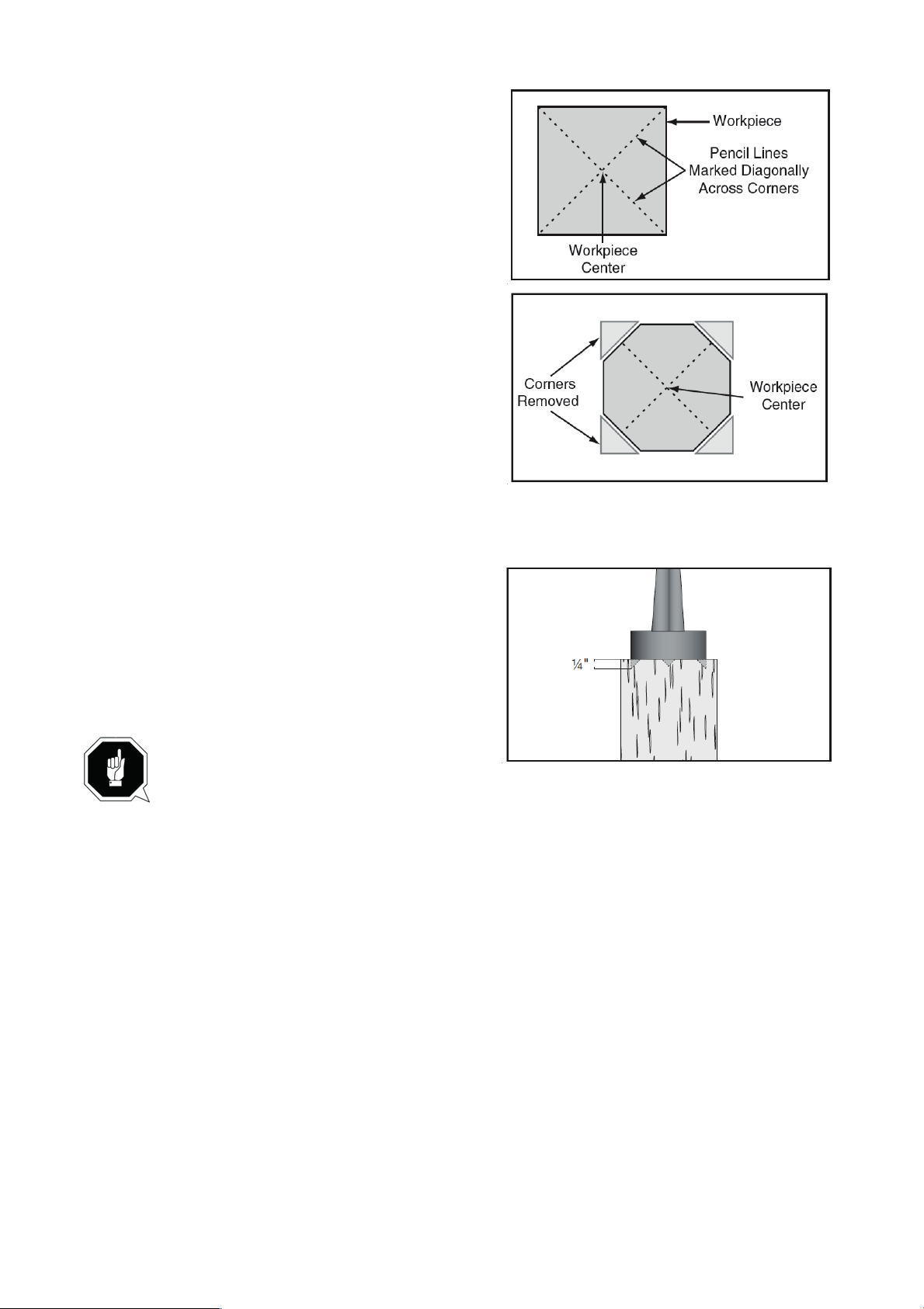
▲ Find center point of both ends of your workpiece
by drawing diagonal lines from corner to corner
across end of workpiece.
▲ Make a center mark by using a wood mallet and
tapping point of spur center into center of workpiece on
both ends.
▲ Using a
1⁄4" drill bit, drill a 1⁄4" deep hole at center
mark on end of the workpiece to be mounted on
headstock spur center.
▲ To help embed spur center into workpiece, cut
1⁄8"
deep saw kerfs in headstock end of workpiece along
diagonal lines marked in Step 1.
▲ If your workpiece is over 2" x 2", cut corners off workpiece lengthwise to make turning safer and
easier.
6. Drive spur center into end center mark of workpiece
with a wood mallet to embed it at least
1⁄4" into
workpiece.
7. With workpiece still attached, insert spur center into
headstock spindle.
Note: Use tool rest to support opposite end
of workpiece so that workpiece and spur center do not separate during installation.
8. Install live center into tailstock quill and tighten quill-lock handle to lock quill in position.
9. Slide tailstock toward workpiece until point of live center touches workpiece center mark, then lock
tailstock in this position.
10. Loosen quill-lock handle and rotate tailstock handwheel to push live center into workpiece at
least 1⁄4".
11. Properly adjust tool rest to workpiece.
12. Before beginning lathe operation, rotate workpiece by hand to ensure there is safe clearance on
all sides.
4.1.1 Spindle turning tips
▲ When turning the lathe ON, stand away from the path of the spinning workpiece until the spindle
reaches full speed and you can verify that the workpiece will not come loose.
▲ Use the slowest speed when starting or stopping the lathe.
▲ Select the right speed for the size of workpiece that you are turning.
▲ Keep the turning tool on the tool rest the ENTIRE time that it is in contact with the workpiece.
▲ Learn the correct techniques for each tool you will use. If you are unsure about how to use the
lathe tools, read books or magazines about lathe techniques, and seek training from experienced
14
Page 18

and knowledgeable lathe users.
The following operation instructions serves as a beginning point for some common lathe operations.
Practice on scrap material to become familiarized with the operation process and make the
necessary adjustments before working on your workpiece.
4.1.2 Roughing out cut
Roughing out is the first step of the lathe operation, which uses the large roughing gouge tool to
smooth out sharp corners to make the workpiece cylindrical. When roughing out a workpiece, run
the lathe at low speed and always cut downhill, from the large diameter side of the workpiece to the
small diameter side.
1. Make sure the lathe turned off and disconnected. The first cut will start about 2 inches from the
tailstock end of the workpiece. Adjust the tool rest to the suitable position and set the lathe to a slow
speed.
2. Plug in and turn on the lathe. Wait for the motor to reach full speed. Place the roughing gouge on
the tool rest about 2 inches from the tailstock end of the workpiece. Slowly and gently raise the tool
handle until the cutting edge comes into contact with the workpiece.
NOTE: Make sure that the tool is being held well on the work, with the bevel or
grind tangent to the revolving surface or the workpiece. This position will generate
a clean shearing cut. Do not push the tool straight into the work.
3. To make the first pass, rolling the flute of the tool (the hollowed-out portion) towards the end of
the tailstock.
4. Make the second pass, starting at about 2 or 3 inches to the left of the first cut. Again, advance
the tool towards the tailstock, and merge with the previous cut.
5. As your cuts get close to the headstock live center end of the workpiece, roll the gouge in the
opposite direction to carry the final cut off the live center end of the workpiece.
Always work towards the end of the workpiece; NEVER start a cut at the end.
6. Make long sweeping cuts in a continuous motion to turn the workpiece to a cylinder. Keep as
much of the bevel of the tool in contact with the workpiece as possible to ensure control and avoid
catches. The roughing cut is continued until the work approaches about 1/8 inch to the required
cylinder diameter.
7. Once the workpiece is roughed down to a cylinder, smooth it with a large skew chisel tool. The
turning speed can be increased. Keep the skew handle perpendicular to the spindle and use only
the center third of the cutting edge for a long smoothing cut (touching one of the points of the skew
to the spinning workpiece may cause a catch and ruin the workpiece).
NOTE: Constantly remember to move the tool rest inward towards the workpiece
to keep a safe distance between the tool and your workpiece.
4.1.3 Creating Beads
Making a parting cut for the desired depth and location of your bead.
1. Place the parting tool on the tool rest and move the tool forward to make the full bevel of the tool
come into contact with the workpiece. Gently raise the handle to make cuts of the appropriate depth.
Repeat for the other side of the bead.
15
Page 19

2. Using a small skew or spindle gouge, start in the center between the two cuts and cut down each
side to form the bead. Roll the tool in the direction of the cut.
4.1.4 Creating coves
Using a spindle gouge to create a cove.
1. With the flute of the tool at 90 degrees to the workpiece, touch the point of the tool to the
workpiece and roll in towards the bottom of the cove. Stop at the bottom, as attempting to go up the
opposite side may cause the tool to catch.
2. Move the tool over the desired width of the cove. With the flute facing the opposite direction,
repeat the step for the other side of the cove. Stop at the bottom of the cut.
4.1.5 Creating V-grooves
Using the point of the skew to create a V-groove in the workpiece.
1. Lightly mark the center of the V with the top of the skew. Move the point of the skew to the right
half of the desired width of your cut.
2. With the bevel parallel to the right side of the cut, raise the handle and push the tool in to the
desired depth. Repeat from the left side.
NOTE: The two cuts should meet at the bottom and leave a clean V-groove.
Additional cuts may be taken to add to either the depth or the width of the cut.
4.1.6 Sanding the workpiece
Adjust the lathe to a slower speed for sanding and finishing. High speed can build friction while
sanding and cause burns in some woods. The cleaner the cuts, the less sanding will be required. So
try to make the cuts as refined as you can before moving to the sanding process.
1. Use sandpaper finer than 120 grit, as coarse sandpaper may scratch the workpiece. Fold the
sandpaper into a pad will allow easier and safer sanding. Do not wrap the sandpaper around your
fingers or the workpiece.
2. Apply light pressure to the workpiece during sanding. Use power-sanding techniques to avoid
concentric sanding marks around your finished piece.
3. Progress through finer grits of sandpaper until the desired surface is achieved. Finish sanding
with 220 grit sandpaper.
4.2 Bowl turning
4.2.1 Mounting the workpiece onto the face plate
When turning bowls or plates with a large diameter, mounting it to the face plate to gives the
maximum amount of support. While face plates are the most reliable method for holding a larger
block of wood for turning, a lathe chucks can also be used. A chuck is handy when working on more
than one piece at a time, allowing you to open the chuck and change workpieces instead of having
to remove the mounting screws.
1. Select a stock that is at least .2 inches (5 mm) larger than each dimension of the finished
workpiece.
2. Remove any bark from the top of the wood stock (that will be later attached onto a face plate or in
a chuck).
3. True one of the surfaces of the workpiece for mounting against the face plate. Using the face
16
Page 20

plate as a template, mark the location of the mounting holes on the workpiece and drill pilot holes of
the appropriate size.
If the mounting screws on the face plate will interfere with the workpiece, a waste block can be
used. Shape the waste block so that it is of the
same diameter as the face plate. Flatten the mating
surfaces of the waste block and the workpiece. Use
a high quality glue suitable for the particular
workpiece to prevent the workpiece from falling off
during operation. Glue the waste block to the
workpiece securely. If you plan to use a chuck, turn
the waste block into a tenon of the appropriate
length and diameter to fit your chuck.
4.2.2 To shape the inside of a bowl or plate
▲ Turn off the lathe and move the tailstock out of the way.
▲ Mount the workpiece onto the face plate and install the face plate on to the headstock.
▲ Adjust the tool rest in front of the workpiece to be just below the centerline and at the right angle
to the lathe’s turning axis.
▲ Rotate the workpiece by hand to check for proper seating and clearance.
▲ Begin shaping by lightly shearing across the top of the bowl from rim to center. Place a bowl
gouge tool on the tool rest at the center of the workpiece with the flute facing the top of the bowl.
The tool handle should be level and pointed toward the four o’clock position.
▲ Control the cutting edge of the gouge with the left hand, while swinging the tool handle around
towards your body with the right hand. The flute should start out facing the top of the workpiece,
rotating it upwards as it moves deeper into the bowl to maintain a clean and even curve. As the tool
goes deeper into the bowl, progressively work outwards towards the rim of the bowl. It may be
necessary to turn the tool rest into the piece as you get deeper into the bowl.
NOTE: Try to make one light continuous movement from the rim to the bottom of
the bowl to ensure a clean, sweeping curve through the piece. Should there be a
few small ridges left, a light cut with a large domed scraper can even out the
surface.
Develop the preferred wall thickness at the rim and maintain it as you work deeper into the bowl
(once the piece is thin toward the bottom, you cannot make it thinner at the rim). When the interior is
finished, move the tool rest back to the exterior to re-define the bottom of the bowl. Work the tight
area around the face plate or the chuck with a bowl gouge. Begin the separation with a parting tool,
but do not cut all the way through.
4.3 Turning tools
Lathe tools come in a variety of shapes and sizes, and usually fall into five major categories.
WARNING: Select the right tool for your task at hand. Make sure all tools, chisels
and accessories are sharp before using them.
DO NOT use dull or damaged tools!!
17
Page 21
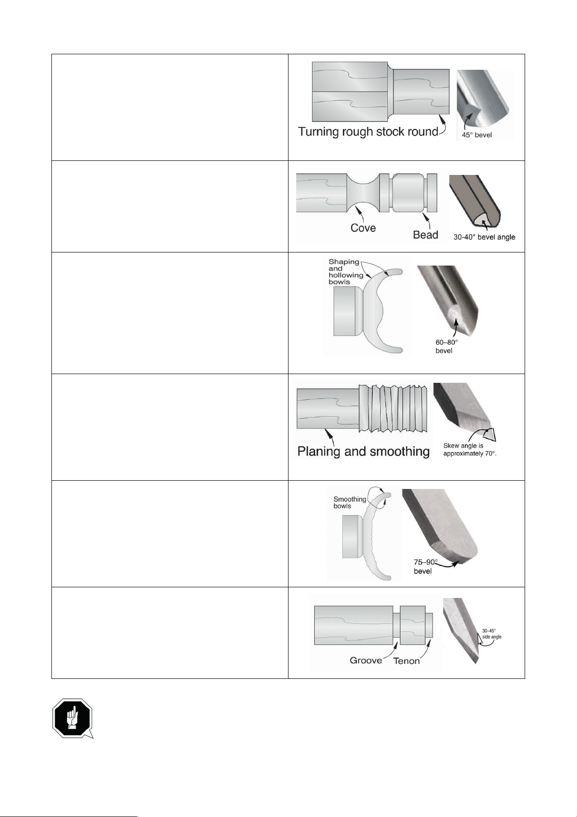
▲ Roughing gouge
cove profiles. The rough gouge is a hollow,
either a round or pointed nose.
he bowl gouge cuts external and internal
mounted stock, such as
bowls and platters. It can also be used for
cutting, beading, and parting off.
20°–40°).
of profiles (round nose, spear point, square
Mainly used for rough cutting, detail cutting, and
double-ground tool with a round nose, and the
detail gouge is a hollow, double-ground tool with
▲ Spindle gouge
The spindle gouge cuts coves, beads and freeform contours. It can also be used for producing
shallow hollows on faceplate turnings.
▲ Bowl gouge
T
profiles on faceplate-
creating ultra smooth cuts on bowls and spindles
by using it as a shearing scraper.
▲ Skew Chisel
A very versatile tool that can be used for planing,
squaring, VThe skew chisel is flat, double-ground with one
side higher than the other (usually at an angle of
▲ Round nose scraper
Typically used where access for other tools is
limited, such as hollowing operations. This is a
flat, double-ground tool that comes in a variety
nose, etc.) to match many different contours.
▲ Parting tool
Use the parting tool to form grooves and tenons
and to remove stock. It can also be used for
rolling small beads.
If possible, select only quality high-speed steel turning tools. High-speed steel
tools hold an edge and last longer than ordinary carbon steel. As one becomes
proficient in turning, a variety of specialty tools for specific applications can be
acquired. The following tools provide the basics for most woodturning project.
18
Page 22

5. Maintenance
This chapter contains important information about
▲ Inspection
▲ Maintenance
ATTENTION!
Properly performed regular maintenance is an essential prerequisite for
operational safety, failure-free operation, a long service life of the wood lathe and
the quality of the products which you manufacture. Installations and equipment from other
manufacturers must also be in good condition.
5.1 Schedule
For optimum performance from this machine, this maintenance schedule must be strictly followed.
Ongoing
Daily Check Monthly Check
To maintain a low risk of injury and proper
machine operation, if you ever observe any of the
items below, shut down the machine immediately
and fix the problem before continuing operations:
• Loose faceplate or mounting bolts.
• Damaged center or tooling.
• Worn or damaged wires.
• Loose machine components.
• Any other unsafe condition.
•Clean off dust buildup.
• Clean and lubricate
lathe bed, spindle, and
quill.
• Belt tension,
damage, or wear.
5.2 Cleaning
Cleaning this lathe is relatively easy. Vacuum excess wood chips and sawdust, and wipe off the
remaining dust with a dry cloth. If any resin has built up, use a resin-dissolving cleaner to remove it.
Protect the unpainted cast-iron surfaces by wiping them clean after every use—this ensures moisture
from wood dust does not remain on bare metal surfaces.
5.3 Lubrication
All bearings on this lathe are lubricated and sealed at the factory, and do not need additional
lubrication.
Wipe a lightly oiled shop rag on the outside of the headstock spindle. DO NOT allow any oil to get on
the inside mating surfaces of the spindle.
Use the tailstock handwheel to extend the quill out to the furthest position and apply a thin coat of
white lithium grease to the outside of the quill.
DO NOT allow any oil or grease to get on the inside mating surfaces of the quill.
19
Page 23
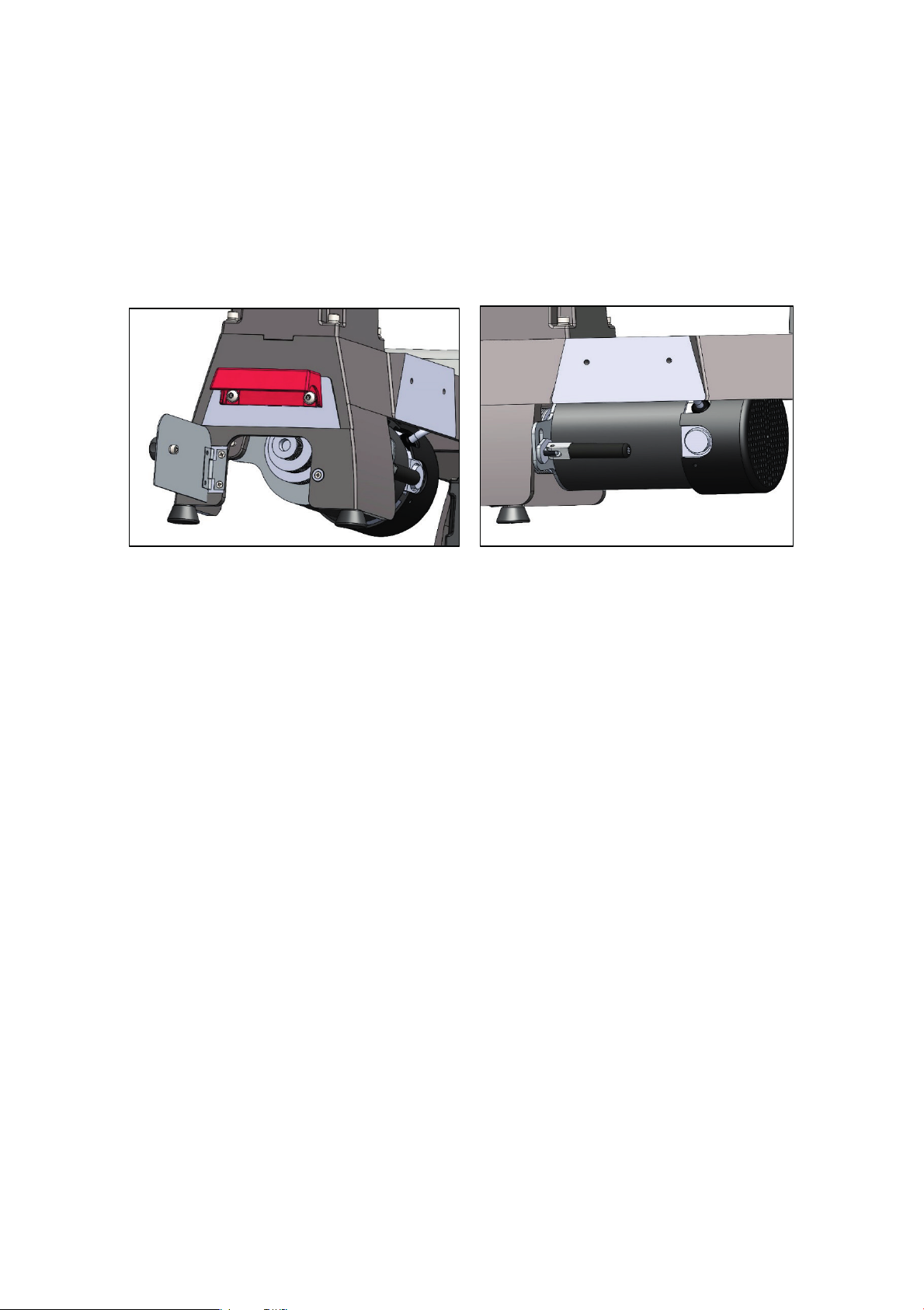
5.4 Tensioning and replacing belt
Most of the stretching will occur during the first 16 hours, but may continue with further use. If the
lathe loses power while making a cut, the belt may be slipping and need tensioning. If the belt shows
signs of excessive wear, or damage, replace it.
5.4.1 Tension belt
1. Disconnect machine from power!
2. Open the front and lower belt drive access plates, and loosen belt-tension lock handle.
3. Press belt with moderate pressure in center to check tension. Belt is correctly tensioned when there
is approximately 1⁄2" deflection.
4. Re-install side access cover and close front access cover.
5.4.2 Replacing belt
1. Disconnect machine from power!
2. Open the front and lower belt drive access plates.
3. Loosen belt-tension locking handle, release belt tension, then remove belt from motor pulley.
4. Unthread and remove spindle handwheel, then remove (3) Phillips head screws from spindle end
cover and remove cover.
5. Move belt around pulley and spindle, then remove belt through upper opening.
6. Insert new belt through lower opening, and pull it around end of spindle onto pulley.
7. Re-install headstock spindle handwheel.
8. Loosely install belt on inner or outermost motor pulley position.
9. Tighten belt-tension lock handle.
10. Follow Step 4 in the Tensioning Belt procedure to set belt tension.
11. Close the front and lower belt drive access plates.
5.5 Replacing brushes (FOR MC1421VDA ONLY)
This machine is equipped with a universal motor that uses a pair of carbon brushes to transmit power.
These brushes are considered to be regular "wear items" or "consumables" that will eventually need
to be replaced. The frequency of this replacement is directly related to how much the motor is used
and how hard it is pushed. These brushes are not covered under warranty.
Replace both brushes at the same time if the motor no longer reaches full power, operates
inconsistently, or when the brushes measure less than 1⁄4" long (new brushes are 5⁄8" long).
20
Page 24
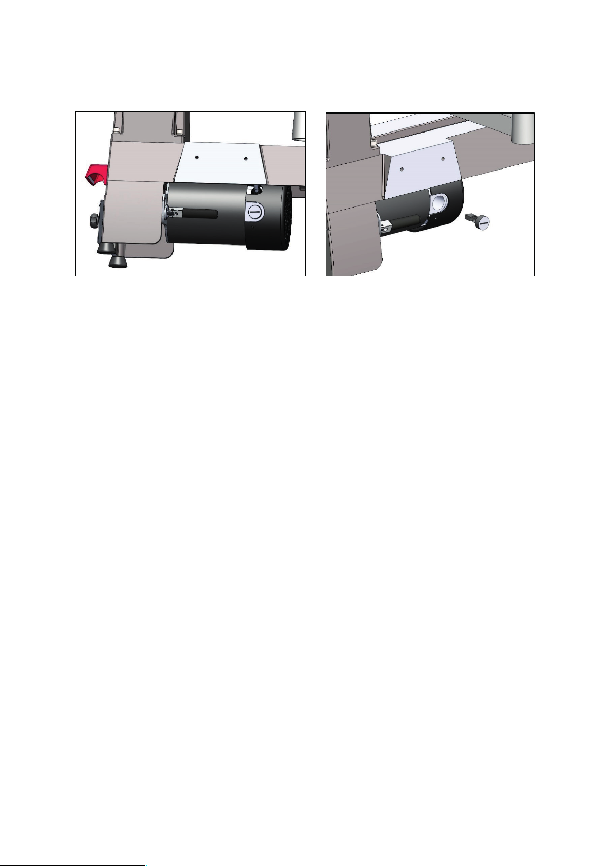
To replace motor brushes:
1. Disconnect machine from power!
2. Use dime to unscrew and remove brush caps on front and rear of motor.
4. Use a ruler to measure wear of each carbon brush. If either brush is worn to less than 1/4" in length,
replace both brushes.
5. Insert new brush assemblies, positioning them to slide into slots in motor sockets. Individually,
press each brush cap against its spring, pushing it into motor socket and turning each brush cap to
lock it into motor housing.
6. Test run machine.
21
Page 25

6. Troubleshooting
6.1 Motor& Electrical
DRO ERROR CODE LIST (FOR MC1421VDA ONLY)
ERROR CODE DESCRIPTION SOLUTION
F1 low voltage protection (20% lower than standard) check voltage, restart lathe
F2 high voltage protection (20% higher than standard) check voltage, restart lathe
F3 incorrect operation of reverse turn off main switch, restart lathe after the
speed display showing "zero"
Symptom Possible Cause Possible Solution
Machine does not
start, or power supply
fuse/breaker trips
immediately after
startup.
Machine stalls or is
underpowered.
Machine has vibration
or noisy operation.
1. Spindle direction switch in neutral
position.
2. OFF button not pressed before toggling
spindle direction switch.
3. Motor brushes worn or at fault.
4. Blown fuse.
5. Power supply circuit breaker tripped or
fuse blown.
6. Motor wires connected incorrectly.
7. Wiring open/has high resistance.
8. ON/OFF switch at fault.
9. Circuit board at fault.
10. Variable-speed potentiometer at fault.
11. Motor at fault.
1. Machine undersized for task.
2. Workpiece material not suitable for
machine.
3. Feed rate/cutting speed too fast.
4. Variable-speed potentiometer at fault.
5. Belt slipping.
6. Motor brushes worn or at fault.
7. Circuit board at fault.
8. Pulley slipping on shaft.
9. Motor at fault.
1. Motor or component loose.
2. Machine sits unevenly on workbench.
3. V-belt worn, loose, or misaligned.
4. Pulley loose.
5. Motor fan rubbing on fan cover.
6. Workpiece/faceplate at fault.
7. Motor mount loose/broken.
8. Motor bearings at fault.
1. Toggle switch to forward/reverse.
2. Press OFF button before toggling spindle
direction switch.
3. Remove/replace brushes.
4. Replace fuse/ensure no shorts.
5. Ensure circuit is sized correctly and free of shorts.
Reset circuit breaker or replace fuse.
6. Correct motor wiring connections.
7. Check/fix broken, disconnected, or corroded
wires.
8. Replace switch/circuit breaker.
9. Inspect/replace if at fault.
10. Test/replace if at fault.
1. Use sharp chisels; reduce feed rate/depth of cut.
2. Only cut wood/ensure moisture is below 20%.
3. Decrease feed rate/cutting speed.
4. Test/replace if at fault.
5. Tension/replace belt; ensure pulleys are aligned,
belts are clean and not damaged.
6. Remove/replace brushes.
7. Inspect/replace if at fault.
8. Tighten/replace loose pulley/shaft.
9. Test/repair/replace.
1. Inspect/replace damaged bolts/nuts, and
retighten with thread-locking fluid.
2. Adjust feet.
3. Inspect/replace belt. Re-align pulleys if necessary
4. Re-align/replace shaft, pulley, set screw, and key.
5. Fix/replace fan cover; replace damaged fan.
6. Center workpiece in chuck/faceplate; reduce
RPM; replace defective chuck.
7. Test by rotating shaft; rotational grinding/loose
shaft requires bearing replacement.
22
Page 26

oil/grease.
6.2 Wood lathe operations
Symptom Possible Cause Possible Solution
Bad surface
finish.
Excessive
vibration upon
startup (when
workpiece is
installed).
Chisel grabs or
digs
into workpiece
Tailstock moves
under load.
Spindle lacks
turning power or
starts up slowly.
Quill will not
move forward
when handwheel
is turned
DRO doesn't give
reading; reading
incorrect.
1. Dull tooling or wrong tool used for task.
2. Tool height is not 1⁄8" above spindle
centerline.
3. Spindle speed is wrong.
4. Excessive vibration.
1. Workpiece is mounted incorrectly.
2. Workpiece warped, out of round, or flawed.
3. Lathe is resting on an uneven surface.
4. Spindle speed too fast for workpiece.
5. Workpiece hitting stationary object.
6. Tailstock or tool rest not securely clamped
to lathe bed.
7. Belt pulleys are not properly aligned.
8. Motor mount bolts are loose.
9. Belt is worn or damaged.
10. Spindle bearings are worn or damaged.
1. Wrong chisel/tool being used.
2. Chisel/tool too dull.
3. Tool rest height not set correctly.
4. Tool rest is set too far from workpiece.
1. Tailstock mounting bolt/hex nut is loose.
2. Bed or clamping surface is excessively oily
or greasy.
1. Belt is slipping.
2. Pulleys loose.
3. Workpiece too heavy for spindle.
1. Shorted/disconnected wiring/plugs.
2. Variable-speed potentiometer at fault.
3. DRO speed sensor at fault.
4. Circuit board at fault.
1. Sharpen tooling, select correct tool for operation.
2. Adjust tool rest so tool is 1⁄8" above spindle
centerline.
3. Adjust for appropriate spindle speed (Page 23).
4. Troubleshoot possible causes/solutions in this table.
1. Remount workpiece, making sure that centers are
embedded in true center of workpiece.
2. Cut workpiece to be concentric, or use a different
workpiece.
3. Adjust feet to eliminate wobble.
4. Reduce spindle speed.
5. Stop lathe and fix interference problem.
6. Check lock levers and tighten if necessary.
7. Align belt pulleys.
8. Tighten motor mount bolts.
9. Replace belt.
10. Test by rotating shaft; rotational grinding/loose
shaft requires bearing replacement.
1. Use correct chisel/tool.
2. Sharpen or replace chisel/tool.
3. Correct tool rest height.
4. Move tool rest closer to workpiece.
1. Tighten mounting bolt/hex nut.
2. Clean bed or clamping surface to remove excess
1. Tighten/adjust belt.
2. Tighten pulley set screw; re-align/replace shaft,
pulley set screw, and key.
3. Remove excess material before remounting; use
lighter workpiece.
1. Align quill keyway and quill lock lever and slightly
tighten lever to engage keyway.
1. Inspect wiring connections on circuit boards,
sensors, and plugs. Replace/repair as necessary.
2. Test/replace if at fault.
3. Test/replace if at fault.
4. Inspect/replace if at fault.
23
Page 27
7. Optional accessories
Installing unapproved accessories may cause machine to malfunction, resulting in serious
personal injury or machine damage. To reduce this risk, only install accessories
recommended for this machine.
7.1 New extension bed
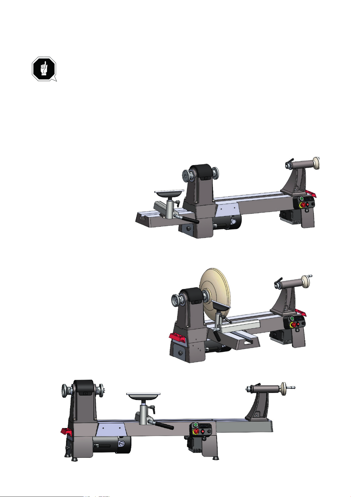
The lathe is designed with three positions for installing the optional extension bed. When installed on
the left side, the maximum swing over bed can reach to 16” for outboard turning. When installed on
the front side of the bed, it could be easily to turn the bottom side of bowls, platters etc. When installed
on the right side, the distance between centers could reach to 34.5” with new 13.5" extension bed and
45" with the original MC1420 extension bed.
On the left side, the maximum
swing over bed can reach to
16” for outboard turning.
On the front side of the bed, it could be
easily to turn the bottom side of bowls,
platters etc.
On the right side, the distance between centers could reach to 34.5”.
24
Page 28
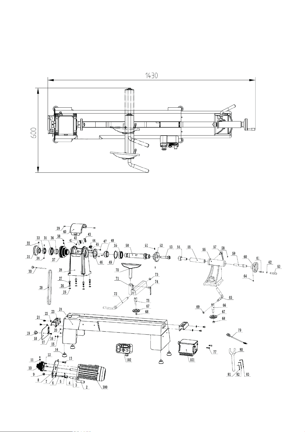
7.1.1 Dimensions
7.1.1 Dimensions
Consider anticipated workpiece sizes and additional space needed for auxiliary stands, work tables,
or other machinery when establishing a location for this machine in the shop.
Below is the minimum amount of space needed for the machine with new extension bed when install
it on the right side of the lathe bed.
Consider anticipated workpiece sizes and additional space needed for auxiliary stands, work tables,
or other machinery when establishing a location for this machine in the shop.
Below is the minimum amount of space needed for the machine with new extension bed when install
it on the right side of the lathe bed.
8. Diagram and part list
8.1 Diagram for MC1421VDB
25
Page 29

8. Diagram and part list
8.1 Diagram for MC1421VDB
8.2 Part list for MC1421VDB
6
Locking screw
1 48
Plastic Spacer
1
8
Motor base
1 50
Spindle
1
9
Hexagon lock nut
1 51
Screw
2
10
Motor Pulley
1 52
Face plate
1
11
Screw
2 53
Spur Center
1
12
Screw
3 54
Live Center
1
18
Bed cover plate
1 60
Tailstock handwheel
1
19
Locking handle
1 61
Handle lever
1
27
Screw
4 69
Elastic retaining ring
1
28
Headstock
1 70
Tool rest
1
29
Belt
1 71
Tool rest base
1
30
Rod
1 72
Eccentric handle
1
31
Spindle handwheel
1 73
Retaining ring
1
34
Screw
2 77
Screw
2
37
Spindle pulley
1 81
Hexagonal wrench
1
38
Screw
2 82
Hexagonal wrench
1
39
Screw
2 83
Hexagonal wrench
1
40
Front access plate
1 100
DC brushless motor
1
41
Screw
1 101
Motor Driver Assembly
1
42
Sensor
1 102
Switch box assembly
1
PART NO. DESCRIPTION QTY
2 Handle sleeve 1
3 Locking handle 1
4 Locking cam 1
5 Elastic cylindrical pin 1
7 Pressing plate 1
13 Screw 1
14 Rubber foot 4
15 Magnet 1
16 Screw 1
17 Screw 1
20 Screw 2
21 Screw 4
22 Flat washer 4
23 Tool holder 1
24 Bed 1
25 Flat washer 4
26 Spring washer 4
32 Screw 1
33 Positioning nut 1
35 Ball bearing 2
36 Spacer 2
43 Bracket 1
PART NO. DESCRIPTION QTY
44 Indexing pin 1
45 Screw 2
46 Bearing cover 1
47 Screw 3
49 Elastic retaining ring 1
55 Quill 1
56 Tailstock 1
57 Handle 1
58 Screw 1
59 Guide screw 1
62 Retaining ring 1
63 Handle 1
64 Screw 1
65 Eccentric Handle 1
66 Tailstock support 1
67 Fixed plate 1
68 Locking nut 1
74 Handle 1
75 Locking support 1
79 Power plug 1
80 Wrench 2
26
27
Page 30
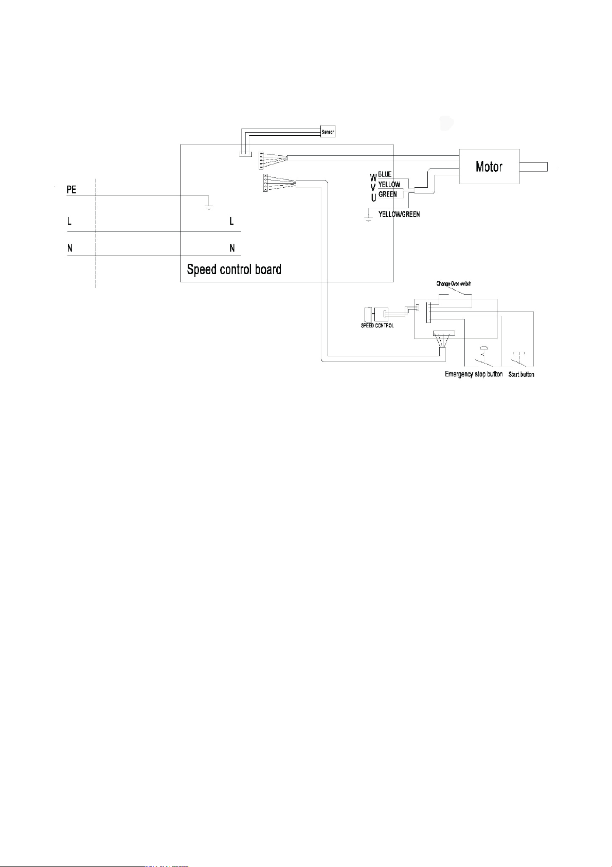
8.3
Wiring diagram for MC1421VDB
Page 31

‘original’
EC DECLARATION OF CONFORMITY
Axminster Tool Centre Ltd
Name and address of person authorised to compile the technical file: Axminster Tool Centre
Ltd, Unit 10 Weycroft Avenue, Axminster, Devon EX13 5PH, United Kingdom The machinery fulfils all relevant provisions of Supply of Machinery (Safety) Regulations 2008
as amended.
Machinery Directive 2006/42/EC
EMC Directive 2014/35/EU
References to the relevant harmonised standards used or references to the other technical
specifications in relation to which conformity is declared:
Product model: AP530WL Name and address of the manufacturer: Axminster Tool Centre Ltd, Unit 10 Weycroft Avenue,
Axminster, Devon EX13 5PH, United Kingdom This declaration of conformity is issued under the sole responsibility of the manufacturer. Object of the declaration: 111887 Axminster Professional AP530WL Bench Lathe 230V
The object of the declaration described above is in conformity with the relevant GB legislation:
ISO 12100:2010 Safety of machinery - General principles for design - Risk assessment and risk reduction
ISO 19085-1:2021 Woodworking machines - Safety - Part 1: Common requirements (ISO 19085-1:2021)
ISO 13857:2019 Safety of machinery - Safety distances to prevent hazard zones being reached by upper and lower limbs (ISO
13857:2019)
ISO 13854:2019 Safety of machinery - Minimum gaps to avoid crushing of parts of the human body (ISO 13854:2017)
IEC 55014-1:2021 Electromagnetic compatibility - Requirements for household appli ances, electric tools and similar apparatus -
Part 1: Emission
Additional information:
IEC 55014-2:2021 Electromagnetic compatibility - Requirements for household appli ances, electric tools and similar apparatus -
Part 2: Immunity - Product family standard.
Signed for and behalf of: Axminster Tool Centre Ltd; (place and date of issue): Axminster, Devon, United Kingdom Kingdom, 24-10-24
Oct 24
th
(name, function): Andrew Parkhouse, Supply Chain Director
Signature:
‘original’
AP530WL Wood Lathe
UK DECLARATION OF CONFORMITY
Axminster Tool Centre Ltd
Supply of Machinery (Safety) Regulations 2008 as amended.
Electromagnetic Compatibility Regulations 2016 as amended.
Name and address of person authorised to compile the technical file: Axminster Tool Centre
Ltd, Unit 10 Weycroft Avenue, Axminster, Devon EX13 5PH, United Kingdom The machinery fulfils all relevant provisions of Supply of Machinery (Safety) Regulations 2008
as amended.
References to the relevant harmonised standards used or references to the other technical
Product model: AP530WL Wood Lathe
Name and address of the manufacturer: Axminster Tool Centre Ltd, Unit 10 Weycroft Avenue,
Axminster, Devon EX13 5PH, United Kingdom This declaration of conformity is issued under the sole responsibility of the manufacturer. Object of the declaration: 111887
The object of the declaration described above is in conformity with the relevant GB legislation:
specifications in relation to which conformity is declared:
ISO 12100:2010 Safety of machinery - General principles for design - Risk assessment and risk reduction
ISO 19085-1:2021 Woodworking machines - Safety - Part 1: Common requirements (ISO 19085-1:2021)
ISO 13854:2019 Safety of machinery - Minimum gaps to avoid crushing of parts of the human body (ISO 13854:2017)
IEC 55014-1:2021 Electromagnetic compatibility - Requirements for household appli ances, electric tools and similar apparatus -
ISO 13857:2019 Safety of machinery - Safety distances to prevent hazard zones being reached by upper and lower limbs (ISO
13857:2019)
Part 1: Emission
Additional information:
IEC 55014-2:2021 Electromagnetic compatibility - Requirements for household appli ances, electric tools and similar apparatus -
Part 2: Immunity - Product family standard.
Signed for and behalf of: Axminster Tool Centre Ltd; (place and date of issue): Axminster, Devon, United Kingdom, 24
(name, function): Andrew Parkhouse, Supply Chain Director
Signature:
Page 32

The packaging is suitable for recycling.
Please dispose of it in a responsible manner.
EU Countries Only
Do not dispose of electric tools together with household waste material.
By law they must be collected and recycled separately.
Axminster Tools, Axminster Devon EX13 5PH
axminstertools.com
 Loading...