

Page 1
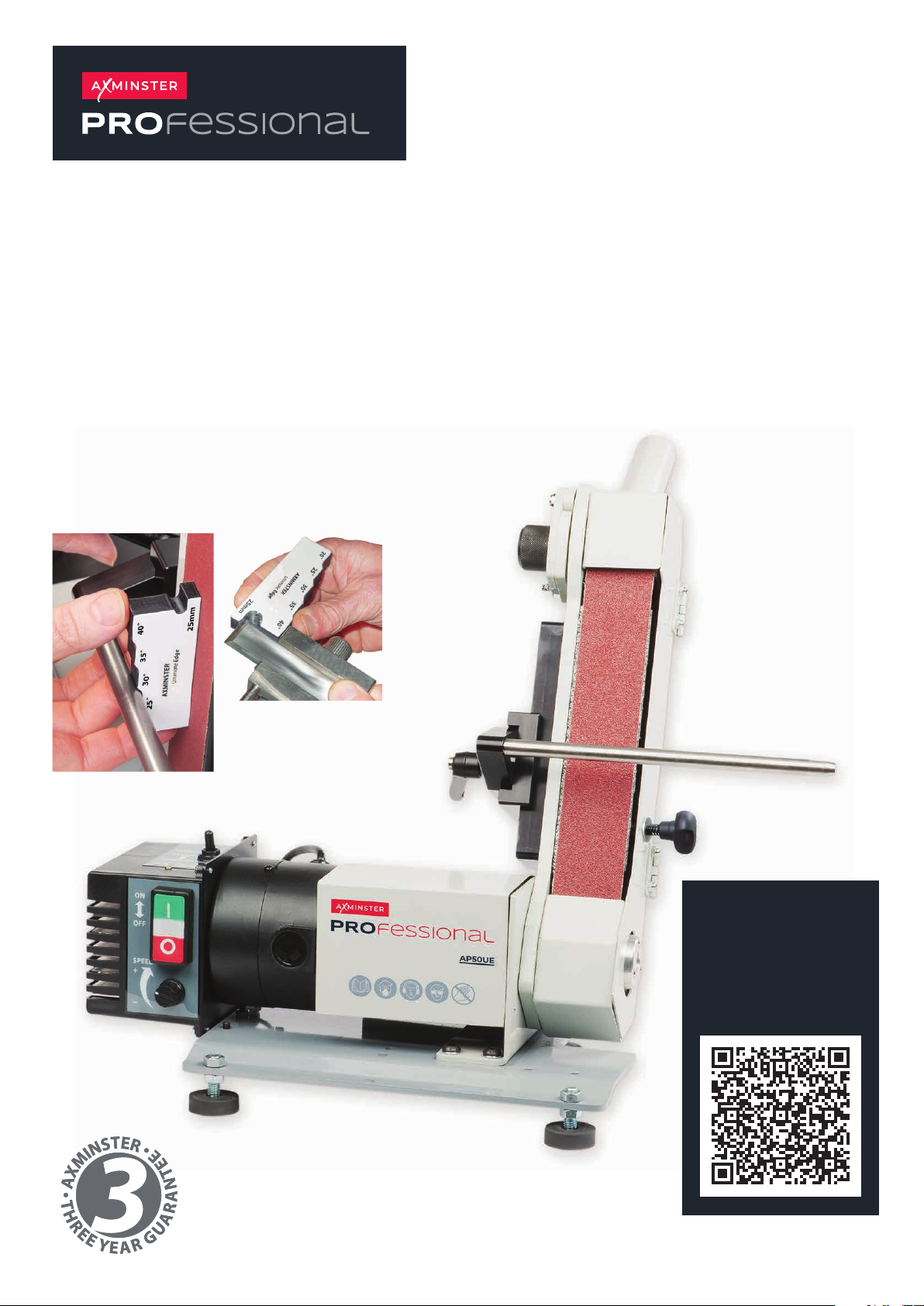
AP50UE
Ultimate Edge Variable
Speed Sharpening System
Code 107658
Original Instructions
Code 106686
Ultimate Edge
Angle Gauge Included
Watch
The Set Up
Guide
Here!
AT: 22/03/2023
BOOK VERSION: 12
Page 2
INDEX OF CONTENTS
EU Declaration of Conformity 02
What’s Included 03
General Instructions for 230V Machines 04
Specification 04
Assembly 04-05-06-07
Illustration & Parts Description 08-09
Setup/Adjustment 10-11
Changing the Belt 12-13
Changing Motor Brushes/Maintenance 13
Support Bar with Dual Axis Adjustment 14-16
Support Bar Assembly 14
Setting the Support Bar 15
Setting the Bar to the Platen 16
Ultimate Edge Angle Gauge 16
Ultimate Edge Accessories 17-18-19-20-21
Polishing Compound Chart 22
Ultimate Edge Online Video 23
Exploded Diagrams/List 24-25-26
Wiring Diagram 26
Spindle Speed Digital Readout Troubleshooting 27
EU DECLARATION OF CONFORMITY
Cert No: DC-P50
Axminster Tool Centre Ltd
Axminster Devon
EX13 5PH UK
axminstertools.com
declares that the machinery described:-
Type Ultimate Edge
Model AP50UE
Signed
Andrew Parkhouse
Operations Director
Date: 08/05/2022
The symbols below advise the correct safety procedures when using this machine.
EU Declaration of Conformity
This machine complies with the following directives:
2006/42/EC
2014/35/EU
EN ISO 12100:2010
EN ISO 60204-1:2006+AC:2010
conforms to the machinery example for which the
EC Type-Examination Certificate No M.2016.201.N1187, 14091705IDA 15001
has been issued by UDEM International Certification Auditing
Training Centre Industry and Trade Co.Ltd
at: Mullukent Mahallesi 2073 Sokak (Eski 93 Sokak) No: 10 Cankaya-Ankara-TURKEY
and complies with the relevant essential health and safety requirements.
Fully read manual
and safety instructions
before use
Ear protection
should be worn
Eye protection
should be worn
2
Dust mask
should be worn
HAZARD
Page 3
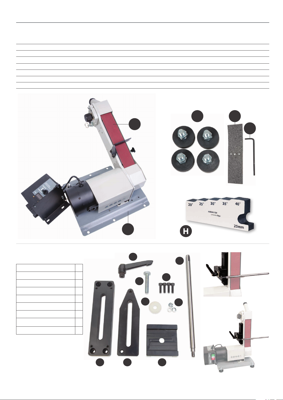
WHAT’S INCLUDED
Model Number AP50UE
Quantity Item Part
1 Ultimate Edge Variable Speed Sharpening System A
1 Abrasive Belt (Fitted) B
4 Adjustable Rubber Feet C
1 Graphite Pad (Self Adhisive) D
1 Long Hex Key 4mm E
1 Ultimate Edge Angle Gauge H
Code 103738
Support Bar with Dual Axis Adjustment
• Clamping Handle A
• Large Bolt B
• Four Caphead Screws C
• Large Clear Washer D
• Four Spring Washers E
• Round Bar F
• Adjustable Mounting Plate G
• Round Bar Mounting Plate H
A
A
B
B
D
C
C
D
E
H
F
E
• Mounting Plate Cradle I
G
H
I
3
Page 4
GENERAL INSTRUCTIONS FOR 230V MACHINES
The following will enable you to observe good working
practices, keep yourself and fellow workers safe and maintain
your tools and equipment in good working order.
WARNING!! KEEP TOOLS AND EQUIPMENT
OUT OF REACH OF YOUNG CHILDREN
KEEP WORK AREA AS UNCLUTTERED AS IS
PRACTICAL. UNDER NO CIRCUMSTANCES SHOULD
CHILDREN BE ALLOWED IN WORK AREAS.
Mains Powered Tools
• Tools are supplied with an 13 Amp UK plug.
• Inspect the cable and plug to ensure that neither are
damaged. Repair if necessary by a suitably qualified person.
• Do not use when or where it is liable to get wet.
Workplace
• Do not use 230V a.c. powered tools anywhere
within a site area that is flooded.
• Keep machine clean.
• Leave machine unplugged until work is about to commence.
• Always disconnect by pulling on the plug body and not the
cable.
• Carry out a final check to the machine.
• Ensure you are comfortable before you start work,
balanced, not reaching etc.
• Wear appropriate safety clothing, goggles, gloves,
masks etc. Wear ear defenders at all times.
• If you have long hair wear a hair net or helmet to prevent it
being caught up in the rotating parts of the machine.
• Consideration should be given to the removal of rings and
wristwatches.
• Consideration should also be given to non-slip footwear etc.
• Do not use the machine if you are tired or distracted
• Do not use this machine within the designated safety areas
of flammable liquid stores or in areas where there may be
volatile gases.
• OBSERVE…. make sure you know what is happening
around you and USE YOUR COMMON SENSE.
SPECIFICATION
Code 107658
Model AP50UE
Rating Trade/Professional
Power DC 230V 50Hz 560W
Motor Speed 3,000 rpm
Motor Pulley Diameter 56 mm
Belt Speed (Metres Per Minute) 202-600 mpm
Belt Size 50 mm x 785 mm
Dust Extraction Outlet 32 mm
Overall L x W x H 540 x 280 x 520 mm
Weight 17.5 kg
Assembly
Fig A
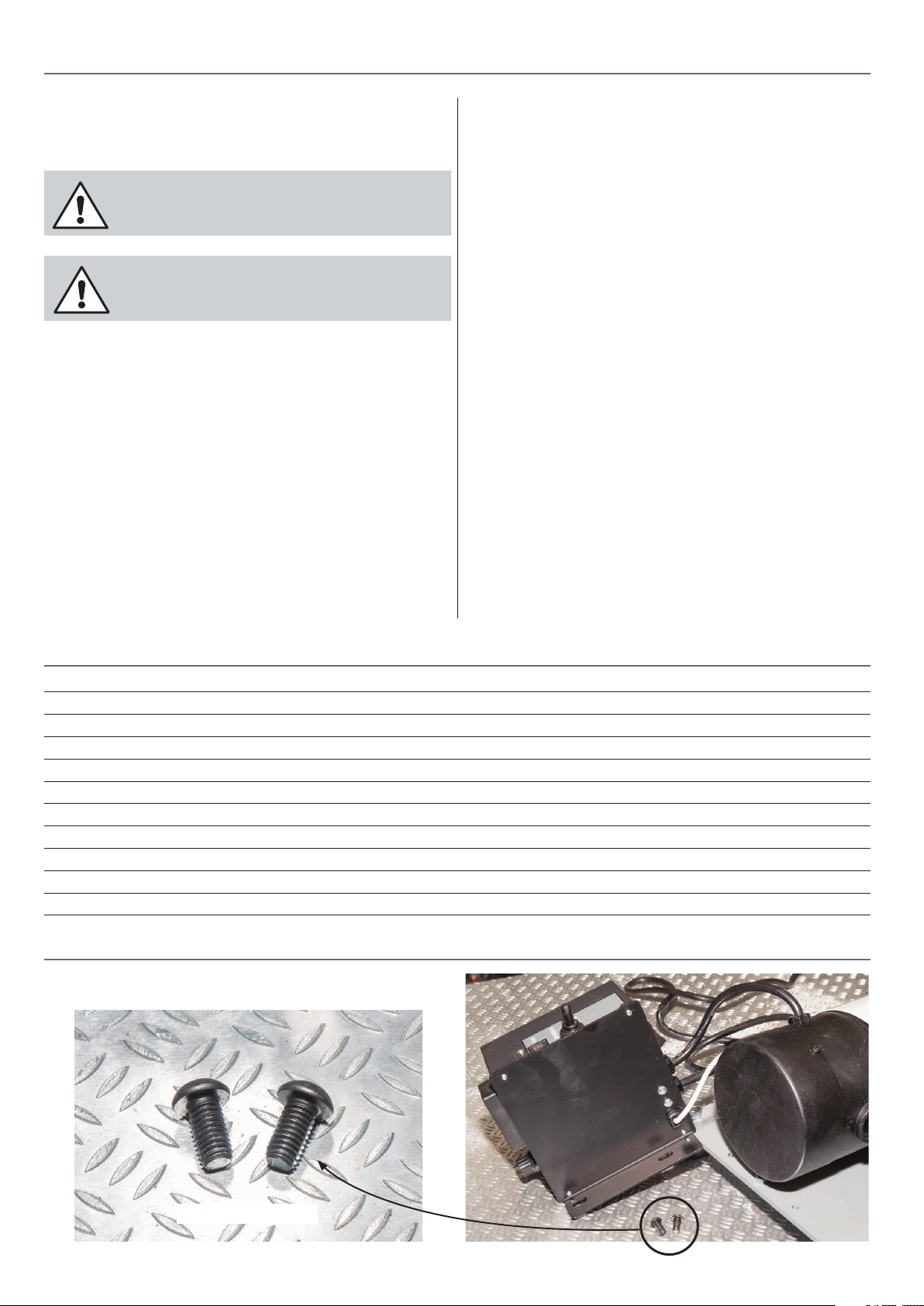
Domed Hex screws
4
Page 5
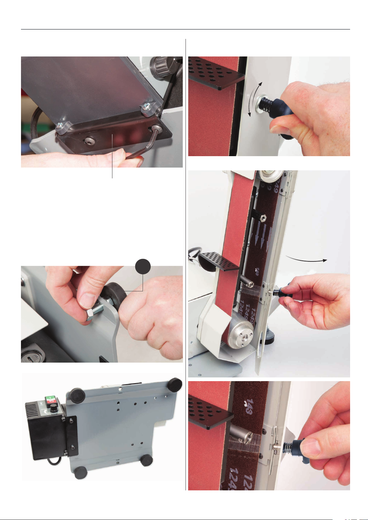
ASSEMBLY
Fig B
Control box assembly
Threaded Rubber Feet
Locate the four ‘Rubber Feet’ (C), remove one nut from each
of the threaded feet and place aside. Slot each threaded foot
through the four pre-drilled holes to each corner of the unit’s
base. Replace the nuts, stand the unit upright and adjust each
foot in turn until the machine is level, see fig 01-02.
Fig 03-04-05
Lock
Unlock
Press knob in and twist
Fig 01-02
C
5
Continues over...
Page 6
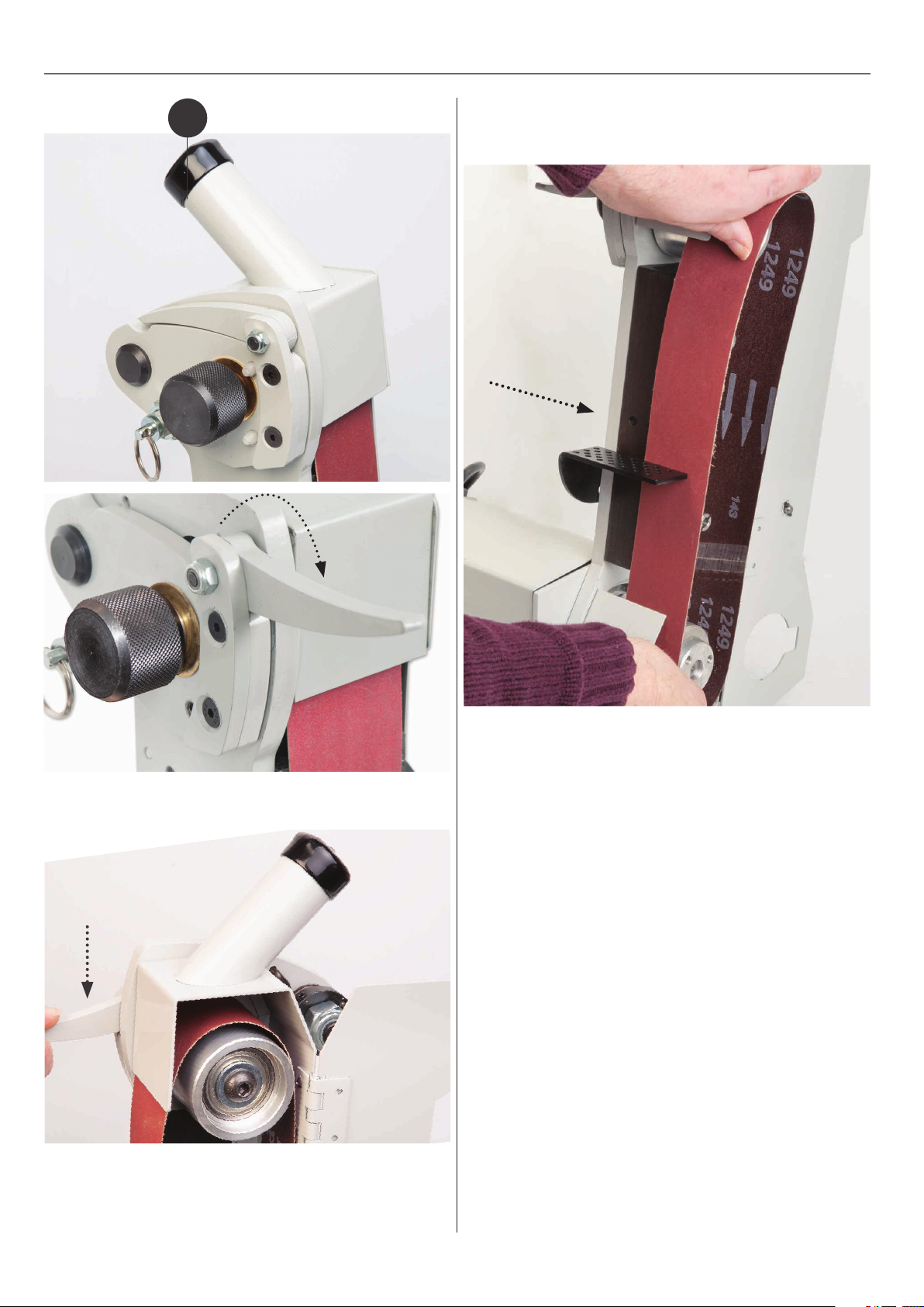
ASSEMBLY
Fig 06-07
3. Remove the belt and place safely aside, see fig 09.
2
Fig 09
Fig 08
Rotate the lever (2) to the side of the platen, see fig 06-07.
Press down the lever to release the belt tension, see fig 08.
There are two options that can be fitted to the ‘Platen’.
• The ‘Platen’ on its own
• The ‘Graphite Pad’ which is included
For most applications we recommend the fitting of the graphite
pad ,the graphite pad has a self adhesive backing and is stuck
directly onto the front face of the platen.
The graphite pad helps reduce friction between the abrasive
belt and the platen,it also helps with smoother grinding as has
a slight cushion effect between the item being sharpened and
the abrasive belt.
There may be some applications where a more rigid grind is
needed and would recommend to use the platen with no pad
fitted.
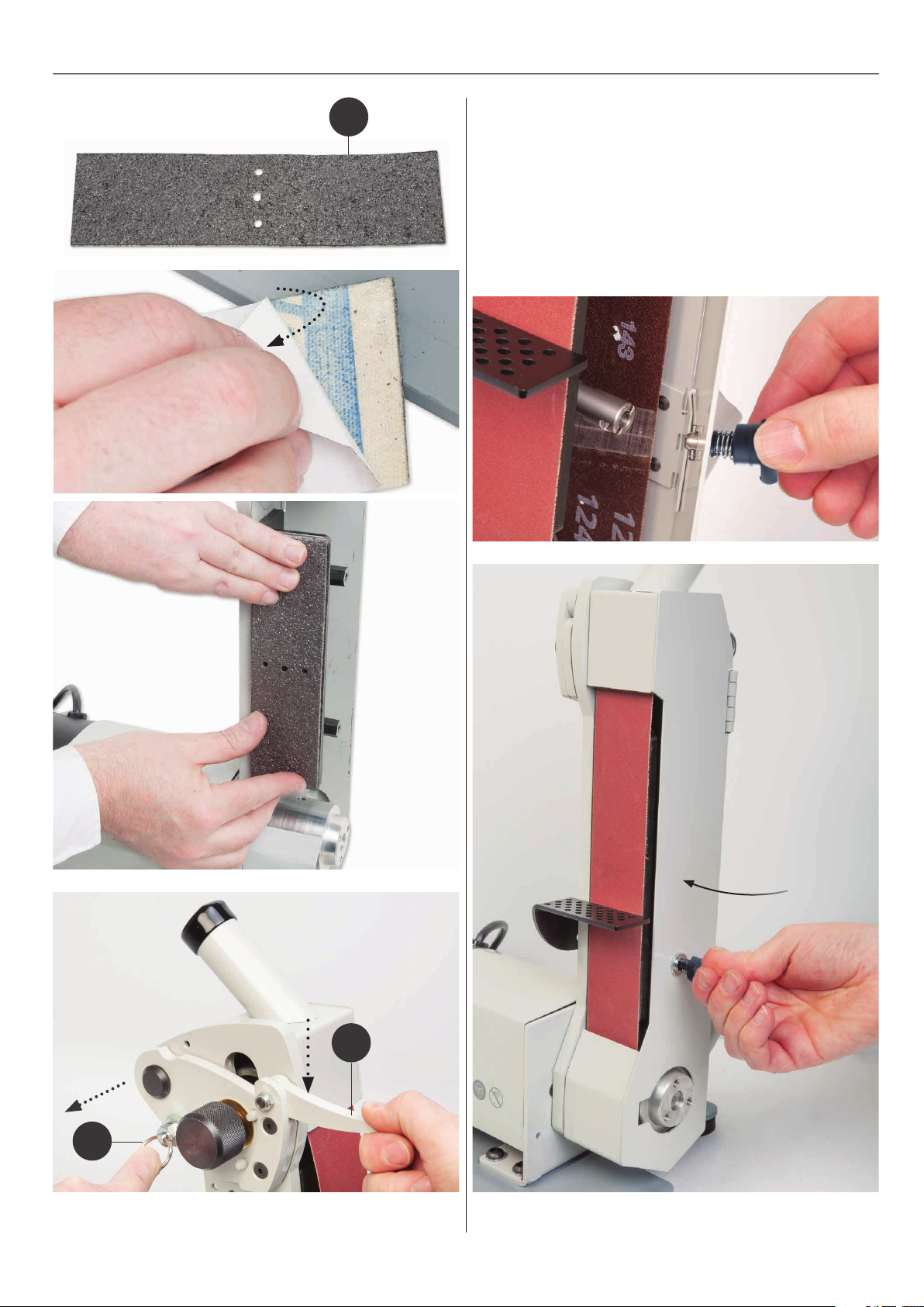
Fitting the Graphite Pad
Locate the ‘Graphite Pad’, (D) and peel off the adhesive backing.
Position the pad down onto the platen and press firmly down,
see fig 10-11-12.
6
Page 7
ASSEMBLY
Fig 10-11-12
D
5. Slide the belt back on and centre the belt on the platen.
Press the lever (2) down and hold in place, pull the locking ‘PIN’
(3) out and raise the platen to re-tension the belt, see fig 13.
6. Close the belt access door and engage the locking pin,
see fig 14-15.
Fig 14-15
Fig 13
3
2
7
Page 8
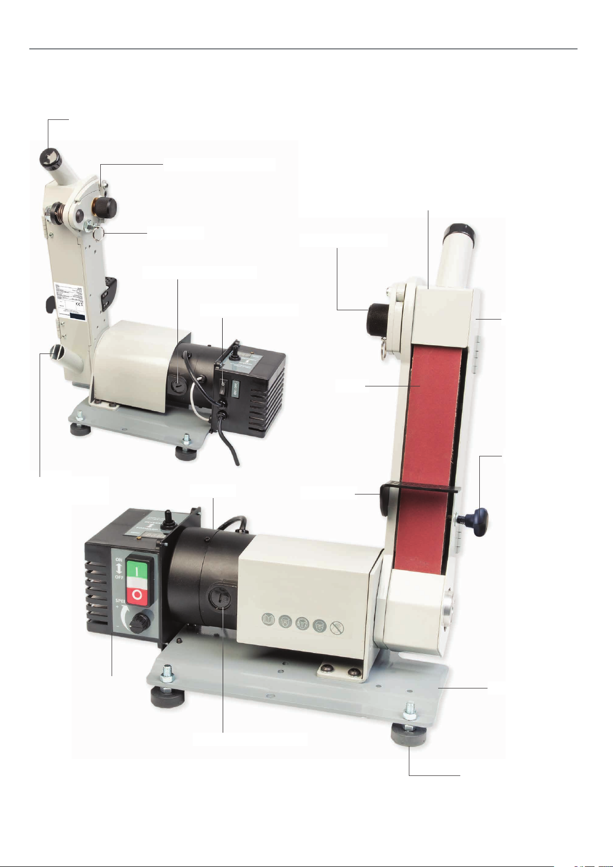
ILLUSTRATION & PARTS DESCRIPTION
32mm Upper dust
extraction outlet
Belt tension mechanism
Belt Guard
32mm Lower dust
extraction outlet
Locking pin
Motor brush access cap
Main ON/OFF switch
Motor
Belt tracking knob
Belt door
Belt
Locking knob
Work table
Control box
Base plate
Motor brush cap
Adjustable rubber foot
8
Page 9
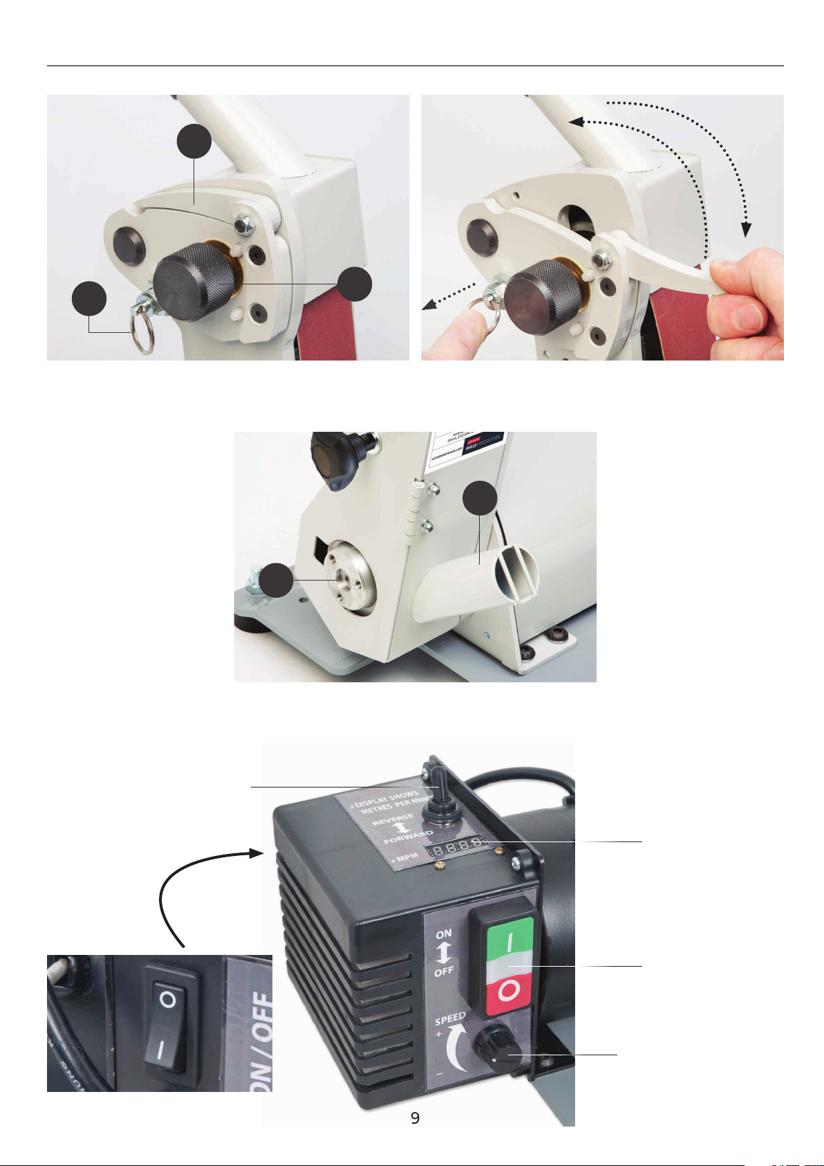
A
ILLUSTRATION & PARTS DESCRIPTION
C
B
Locking pin for tension mechanism (A), Tracking control knob
(B), Operating lever (C) to release the tenstion to the belt
G
32mm Lower dust extraction outlet (F)
Belt tension mechanism
F
Foward/Reverse selector switch
Main ON/OFF switch
Belt speed (MPM)
Meters Per Minute
ON/OFF buttons
Speed control dial
9
Page 10
SETUPADJUSTMENT
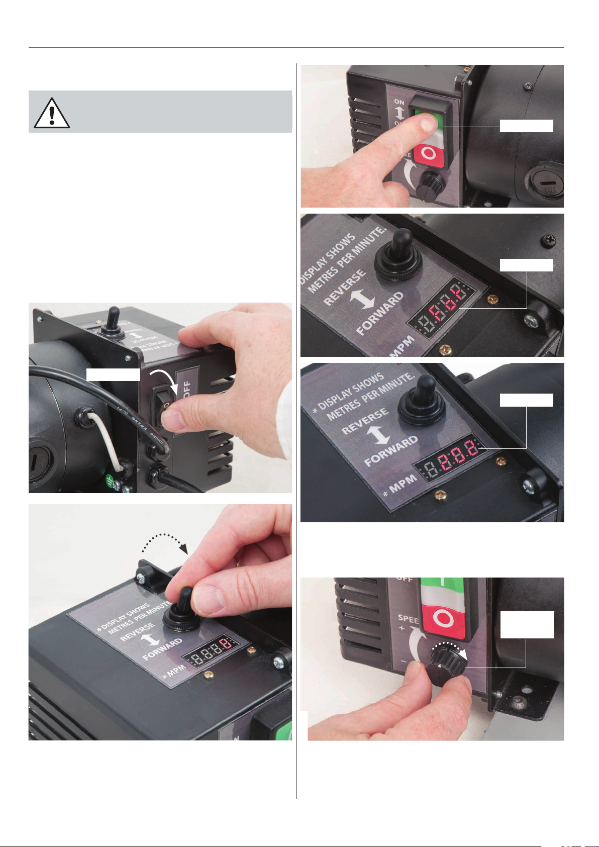
Selector switch in the
forward position
Tracking the Belt
CONNECT THE MACHINE TO THE
MAINS SUPPLY!
1. Press the main ON/OFF on switch to the ‘ON’ position,
see fig 21.
2. Move the selector switch to the ‘Forward’ position, see fig 22.
3. Make sure the speed control dial is turned right down then
press the ‘GREEN’ button to start the machine, see fig 23. The
digital diaplay will read ‘For’ (Forward) then ‘202’ (MPM) will
light up, see fig 24-25.
Fig 21-22-23-24-25
Switch ON
Forward
Power ON
202 (MPM)
4. Turn the speed control knob until the display reads around
‘400’ (MPM), see fig 26
Fig 23
Increase
speed
10
Page 11
SETUPADJUSTMENT
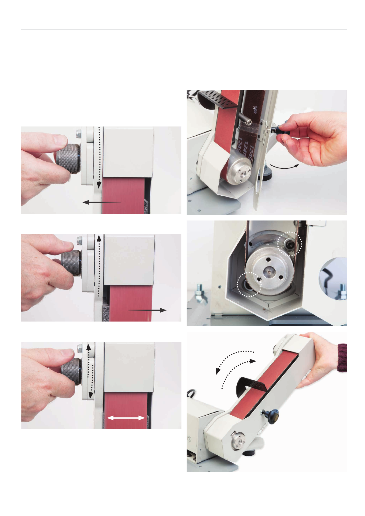
5. Turn the ‘Tracking Knob’ until the belt is centred on the
platen, see fig 27-28-29.
NOTE: Don’t make sudden adjustments otherwise you
may over correct. Make small adjustments.
NOTE: The belt may require re-tracking from forward
to reverse and vise versa.
Fig 27-28-29
Turning the tracking knob clockwise
moves the belt to the left
Setting the Platen Angle
The platen can be pivoted to the required angle by loosening
the two button Hex screw , see fig 31. Lower the plat en to the
required angle, see fig 32. Re-tighten the Hex screws to secure
the setting.
Fig 30-31-32
Turning the tracking knob anti-clockwise
moves the belt to the right
Making small adjustments to centre
the belt on the linisher
6. Once complete, press the ‘RED’ button to stop the machine.
7. Switch off the main ON/OFF switch to isolate the machine.
11
Page 12
CHANGING THE BELT
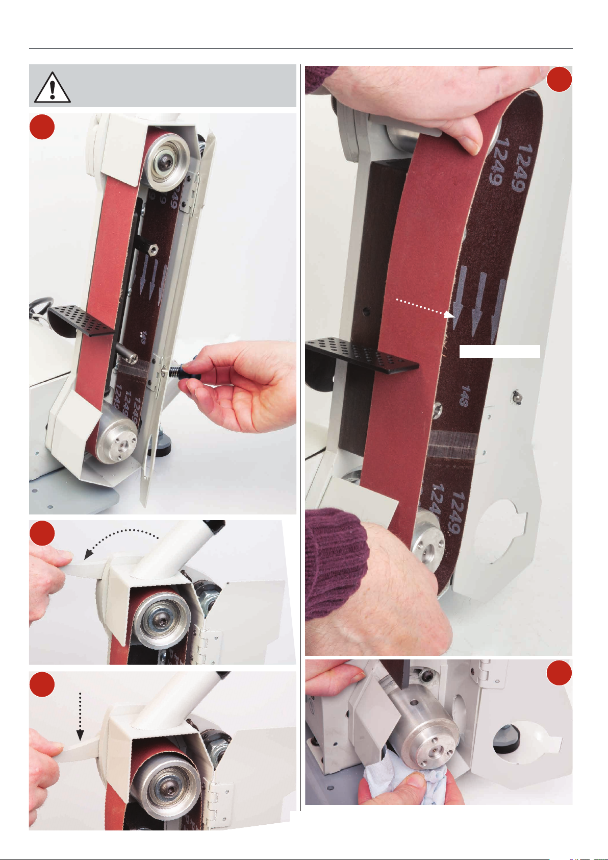
1
DISCONNECT THE MACHINE
FROM THE MAINS SUPPLY!
4
Remove old belt
2
3
5
Clean inside the drive belt assembly
12
Page 13
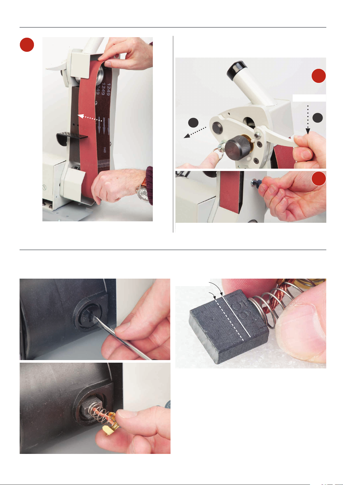
CHANGING THE BELT
6
Press down the lever and hold in place, pull the locking pin out
and raise the roller assembly to re-tension the belt.
7
Press down
1
2
Pull locking pin
8
CHANGING MOTOR BRUSHES MAINTENANCE
Check the condition of the motor brushes every 5-6 months.
Unscrewing each brush cap screw in turn.
Replace the belt and close the door.
Check the condition of the motor brushes and replace just
before the index line.
Index mark
Replace mark
There is very little mechanical maintenance that can be carried
out on the machine, keep the machine clean.
1. Remove the belt plate and check there is no dust or resin
build up on the pulleys or at the edges of the platen.
2. Remove all dust deposits and clean the motor using an ‘M’
Class Vaccum Cleaner.
3. Remove the dust extraction hose and check any build up
of deposits inside the hose and extraction outlet.
13
Page 14
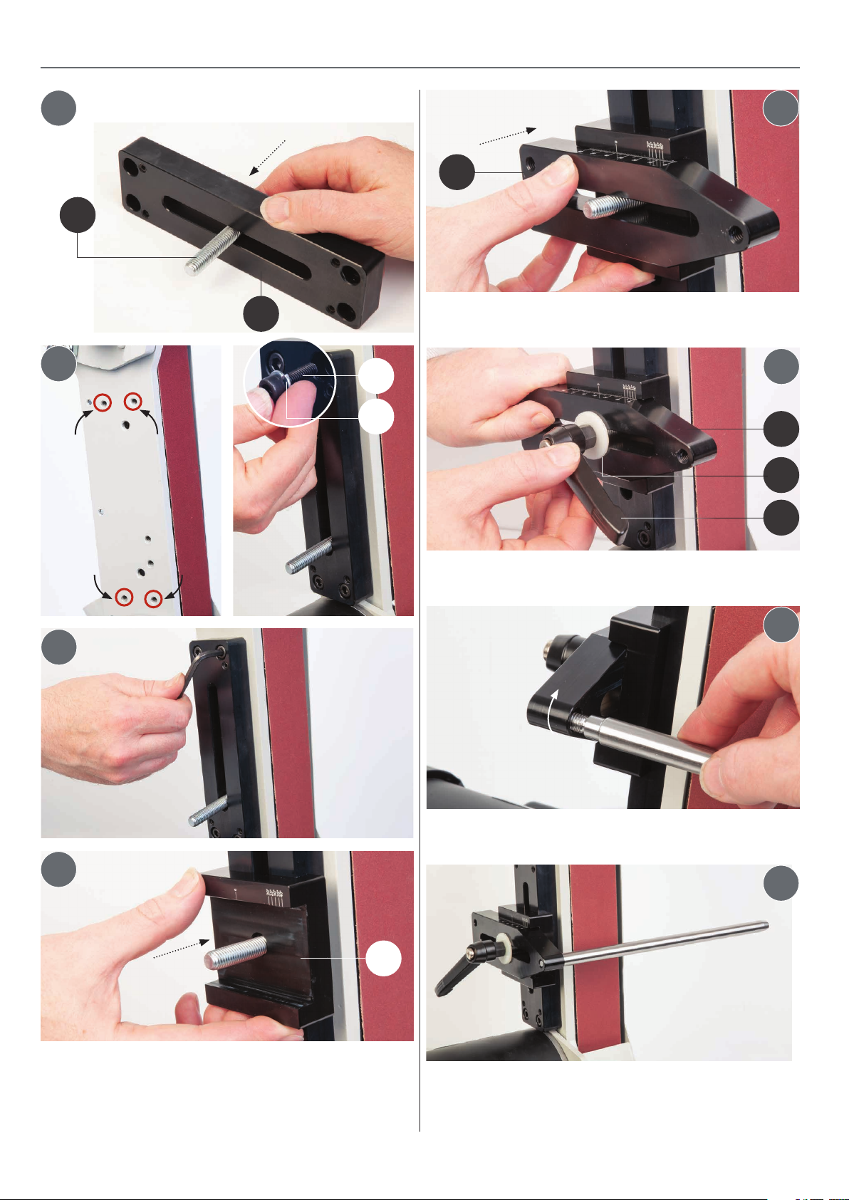
SUPPORT BAR WITH DUAL AXIS ADJUSTMENT
Support Bar Assembly
1
B
Slot the bolt (B) through the
elongated slot in the adjustable
mounting plate (G).
2
Position the plate
(G) against the
platen, line up the
four holes, secure in
position using the
screws (C) & spring
washers (E).
G
C
E
5
H
6
H
D
A
3
4
Tighten the
mounting plate
(G) against the
linisher using a
5mm Hex key.
I
Screw the thread
end of the round
bar (F) into the
thread hole in jig
plate (H).
7
8
Support bar assembled.
Locate the honing guide
assembly and slide the
unit onto the round bar.
Slot the bolt (B) through the pre-drilled hole in the
mounting plate cradle (I), see step 4. Repeat the procedure
for round bar mounting plate (H), see step 5. While holding the
assembly, place the clear washer (D) over the bolt and screw
on the clamping handle (A). Nip-up the handle to secure the
assembly, see step 6.
14
Page 15
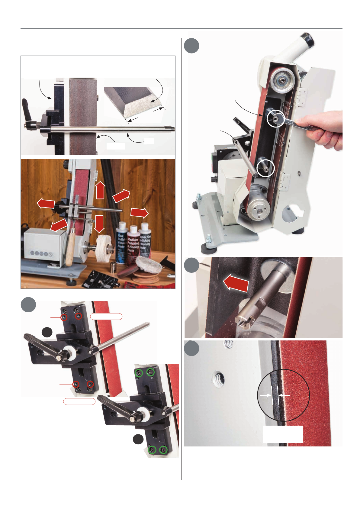
SETTING THE SUPPORT BAR
Terminology of the Support Bar
Support Bar
Left
Front
2
These are the striations,
we call them sharpening lines
Loosen the two studs
25mm
Bar
Bar
Platen
Up
Back
Right
Down
1
Grub screw A
A
Grub screw C
Grub screw D
The ‘RED’ circles in figure (A) shows the
positions of the grub screws used to adjust
the support bar, to the side of the frame. The
‘GREEN’ circles in figure (B) shows the
position of the Hex head screws used to fix
the support bar to the side of the linisher.
Grub screw B
B
3
Platen
4
0.5 to 1mm
Clearance
Loosen the two threaded studs holding the platen. Adjust the
platen so it projects out from the steel frame of about 0.5 to
1mm. Tighten the studs to secure the plat en in place .
15
Page 16
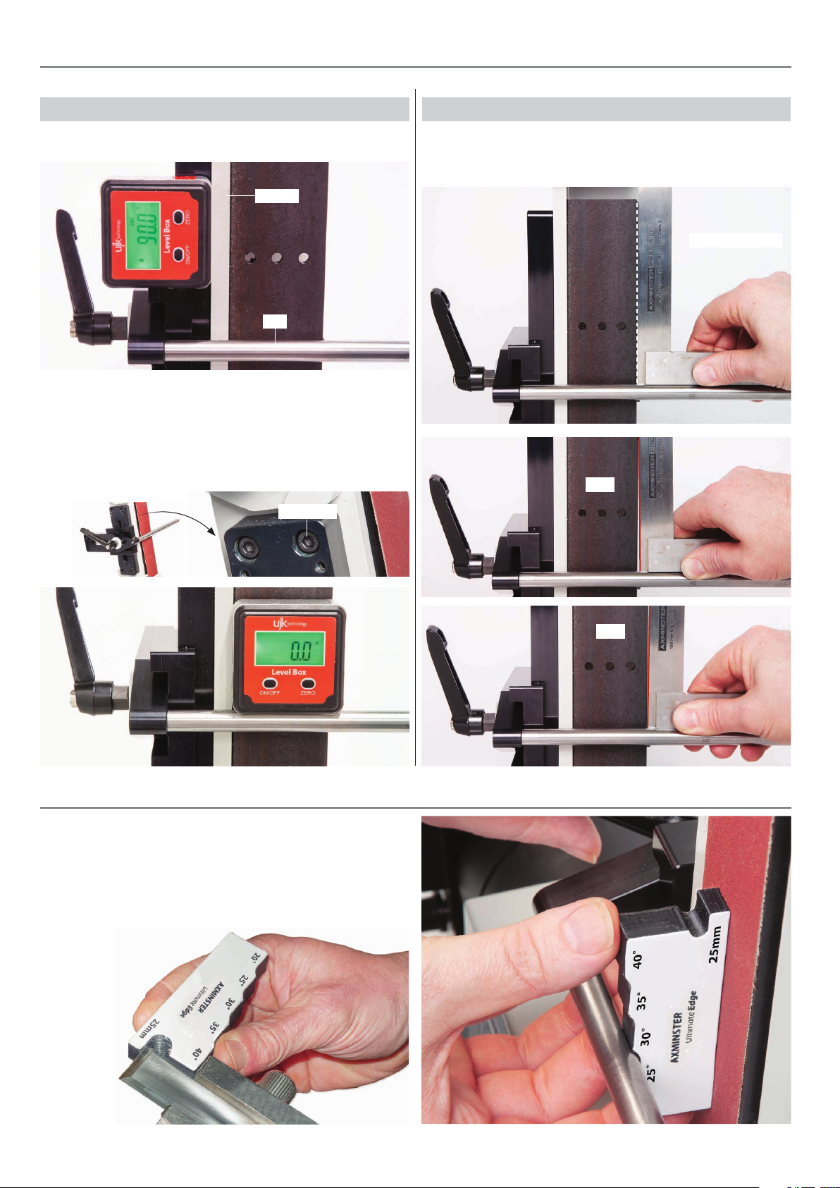
SETTING THE BAR TO THE PLATEN
Method One Method Two
Setting the Bar at 90˚ to the Platen
Linisher
Bar
Using a digital leveling box check the suport bar is perpendicular
to the platen. Place the leveling box onto the bar, it should read
‘ZERO’ on the display. If adjustment is required, lightly loosen the
four Hex screws and adjust the support bar until the ‘Bar’ is in line
with the platen, nip up the Hex screws to secure the assembly .
Hex screw
Alternatively place a 90˚ square on the bar and check its in line
with the edge of the platen and make adjustments accordantly.
Square to the platen
Gap
Ultimate Edge Angle Gauge
The ‘ Angle Gauge ’ tool is a quick and easy way to accurately set
the correct clearence between the platen and the support bar.
The gauge has five preset stops from 20˚ to 40˚ degrees.
The gauge also incorporates a 25mm projection stop to set the
correct projection of the chisel out from the ‘Honing Guide’
assembly.
Gap
16
Page 17
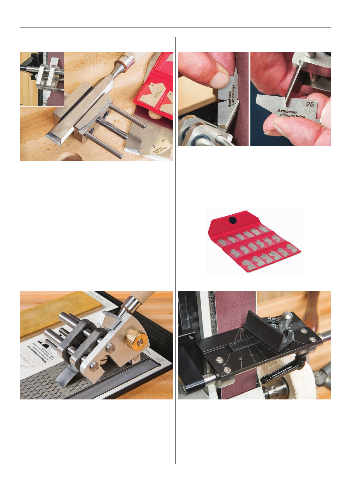
ULTIMATE EDGE ACCESSORIES
Axminster Honing Guide Assembly (code 105281)
The Ultimate Edge Honing Guide is perfect for plane blades,
joinery chisels etc. This fits onto the round bar which is part of
the Support Bar Assembly. Clamping the blade tightly, both
primary and secondary bevels can be achieved if required. The
whole jig is manufactured from stainless steel and has a simple
setting screw to control the width. The LH jaw is reversible
and has twin jaws, one curved so that chisels that do not have
perfectly parallel sides (such as Japanese and old hand forged
chisels) can be clamped, the other jaw being parallel. The jaws
are dovetailed, so securely clamp the tools against the body.
The jaws accommodate blades from 3-66mm in width. A setting
gauge is provided to enable the correct sharpening angle to
be set based upon a standard projection of the cutting tool at
25mm from the guide.
Universal Edge Gauge Setting (code 103730)
As with all accurate sharpening, it’s all about the angles and
our 18 piece set gives all angles from 90° through to 5°. The
set is perfect for setting up sharpening guides as well as
checking ground angles. The UJK level box is an additional
useful accessory for the Ultimate Edge, its ability to record
and set angles is perfect for this application.
Angle Gauge Set In Wallet 5-90 Deg
Ultimate Edge Micro Bevel Gauge (code 105427)
Having ground the primary bevel on any tool the secondary
bevel or micro bevel actually does the majority of the work.
It is exactly what it says it is; a micro bevel which can be
increased with ease each time the tool becomes dull. The
micro bevel guide is made of stainless steel and aluminium
and has the ability to accept the tool still mounted in the
honing guide. The precise angle of the micro bevel can be
easily set and with a few positive passes over a fine diamond
or waterstone, a superb edge can be achieved.
Universal Sharpening Table (code 105426)
This table is an accessory for the Ultimate Edge Support Bar.
This is machined from anodised alloy and is supplied with a
mitre setting guide. The table is locked by a handle locking
securely onto the round bar. Anodised in black, there is a
quadrant of angles laser marked into the surface for easy
reference. Ideal for freehand lathe tool sharpening and
general linishing. Size 130 x 75mm.
17
Page 18
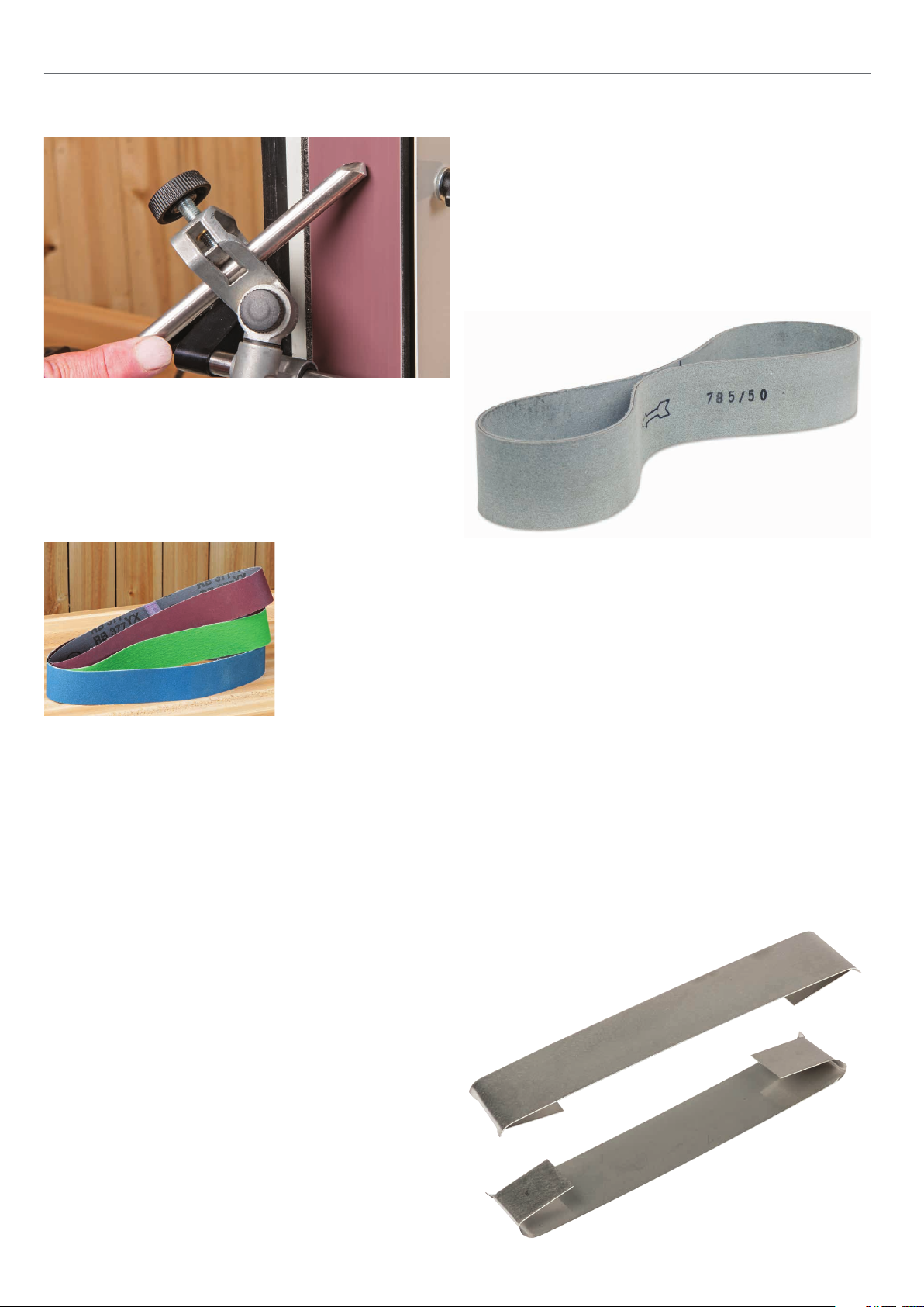
ULTIMATE EDGE ACCESSORIES
Tormek
Many of the Tormek® jigs work amazingly well on the 12mm bar
of the Ultimate Edge and provide the user with extremely sharp
and accurately ground tools. The Tormek fingernail grinding jig
is shown using an aluminium oxide belt with a 65mm
protrusion. See the Tormek® pages for full details.
Belts and Accessories for the Ultimate Edge Machine
belt. As well as abrasive belts we have added a high quality ultra
flexible leather honing belt which can be used with the various
polishing pastes. For general use we recommend aluminium
oxide at about 180g working finer to 400g for final finishing
before any secondary bevel is applied using an ultra fine
diamond or waterstone. 3M’s Trizact abrasive is ideal for final
grinding of all materials resulting in a fine edge ready to use
straight off the machine. This is a different abrasive from normal
convention but equates to 600G, 1200G and 3000G Note: if dust
extraction is to be used, a fireproof hose should ALWAYS be
used (106624).
®
Jigs for Gouges (code 102132)
There are many different
types of abrasive ideally
suited to the purpose
of metal sharpening or
grinding. W e have
listed below the most
popular ones and will
add online a number of
other types of abrasive
Hermes FB637 Blue Film 785 x 50mm Belt 1500G 105554
Hermes FB637 Blue Film 785 x 50mm Belt 2500G 105555
Slip Plate 105676
Red Medium Grade Paste 103703
Blue Fine Grade Paste 103715
White Super Fine Paste 103716
Flame Retardant Extraction Hose 25mm x 2m 103717
Axminster Profiled Honing Wheel
Code 104737
• A three layer belt with a nylon core and two layers of chr ome
tanned leather
• Always use the belt in a clockwise direction
(belt travelling away from the blade tip)
• Never use the belt in a anti-clockwise direction
(belt travelling towards the blade tip)
Axminster Steel Slip Plate
Code 105676
This simple piece of thin steel clips onto the platen of the
Ultimate Edge Sharpening System and covers the graphite
slip plate. While the graphite slip plate helps the abrasive belt
move evenly over the platen when pressure is applied, there are
times when a firmer surface may be required. This is especially
important when sharpening wider flat bevels on plane irons for
example. The steel slip plate is easy to remove after use.
Description Grit Code
Alu Oxide Cloth Belt 785 x 50mm 120G 105233
Alu Oxide Cloth Belt 785 x 50mm 180G 105234
Alu Oxide Cloth Belt 785 x 50mm 240G 105235
Alu Oxide Cloth Belt 785 x 50mm 320G 105236
Zirconium Cloth Belt 785 x 50mm 60G 105238
Alu Oxide Cloth Belt 785 x 50mm 400G 105237
Zirconium Cloth Belt 785 x 50mm 120G 105239
Trizact Abrasive Belt 50 x 785mm A30 600G 105428
Trizact Abrasive Belt 50 x 785mm A16 1,200G 105429
Trizact Abrasive Belt 50 x 785mm A6 3,000G 105430
Hermes FB637 Blue Film 785 x 50mm Belt 800G 105553
18
Page 19
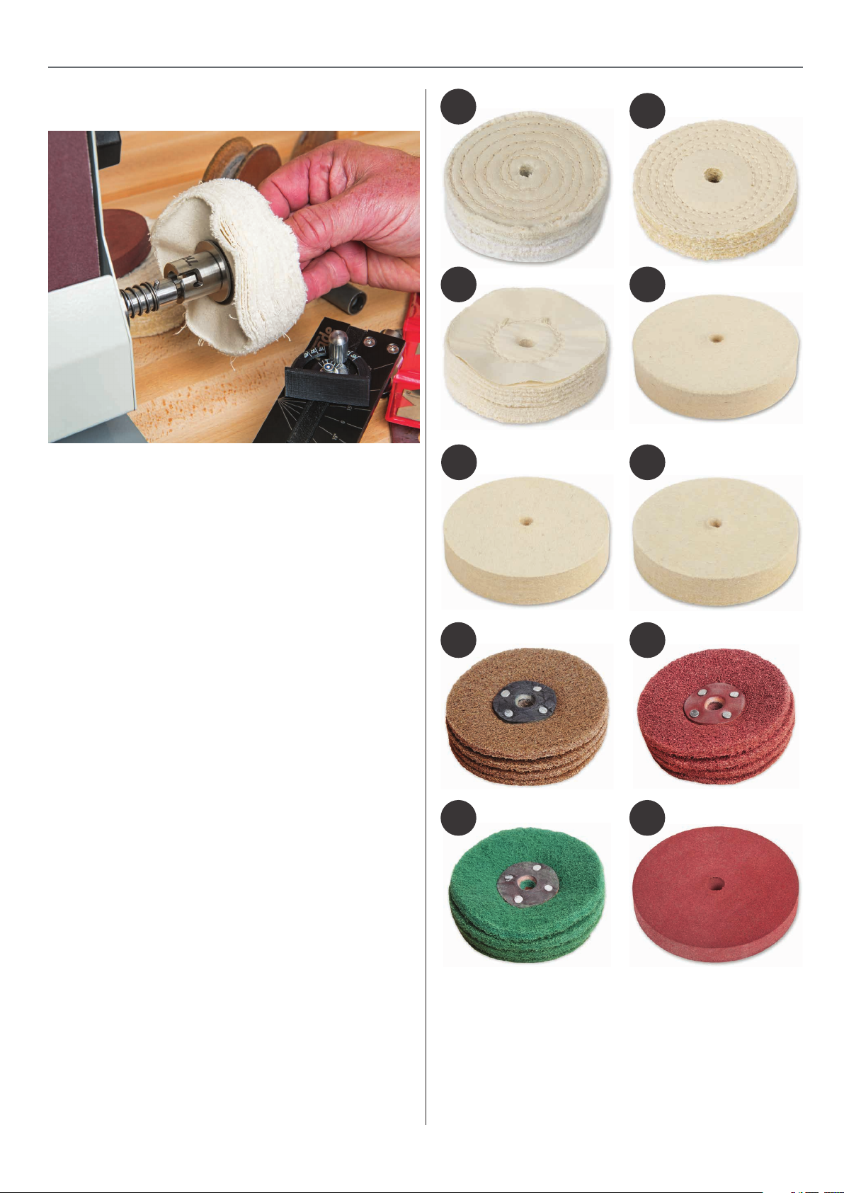
ULTIMATE EDGE ACCESSORIES
Polishing and Honing “Twist & Fix” Arbor (code 105419)
The unique “Twist & Fix” multipurpose arbor allows for the
virtually instant change of different mops, felt wheels and
profiling wheels. Supplied with mounting screws and one
“Twist & Fix” arbor, additional arbors can be purchased
singularly or in a set of 3. This unique 12mm diameter quick
change arbor systems allows the power source to be run in
either forward or reverse direction. Polishing mops, felt wheels
etc should always be used in a specific order; the ability to
change these almost instantly ensures that the process of starting coarse and ending up fine is always followed.
1
2
43
65
7 8
Axminster Polishing and Honing Accessories
A variety of 12mm bore accessories are available for use on
the “Twist & Fix” 12mm arbor including a leather profiled
wheel for carving tools, a rubberised wheel for polishing and
traditional mops both stitched, loose leaf and sisal.
N.B. Smaller sizes of abrasive soaps are available online.
No Description Code
1 4” Standard Stitched Polishing Mop 105422
2 4” Sisal Polishing Mop 105421
3 4” Loose Fold Polishing Mop 105423
4 Felt Wheel for Ultimate Edge - Hard 105580
5 Felt Wheel for Ultimate Edge - Medium 105579
6 Felt Wheel for Ultimate Edge - Soft 105578
7 Nylon Abrasive Wheel - Hard 105583
8 Nylon Abrasive Wheel - Medium 105582
9 Nylon Abrasive Wheel - Soft 105581
10 Rubber Sharpening/Honing
Wheel 100 x 13 x 12mm 105202
109
19
Page 20
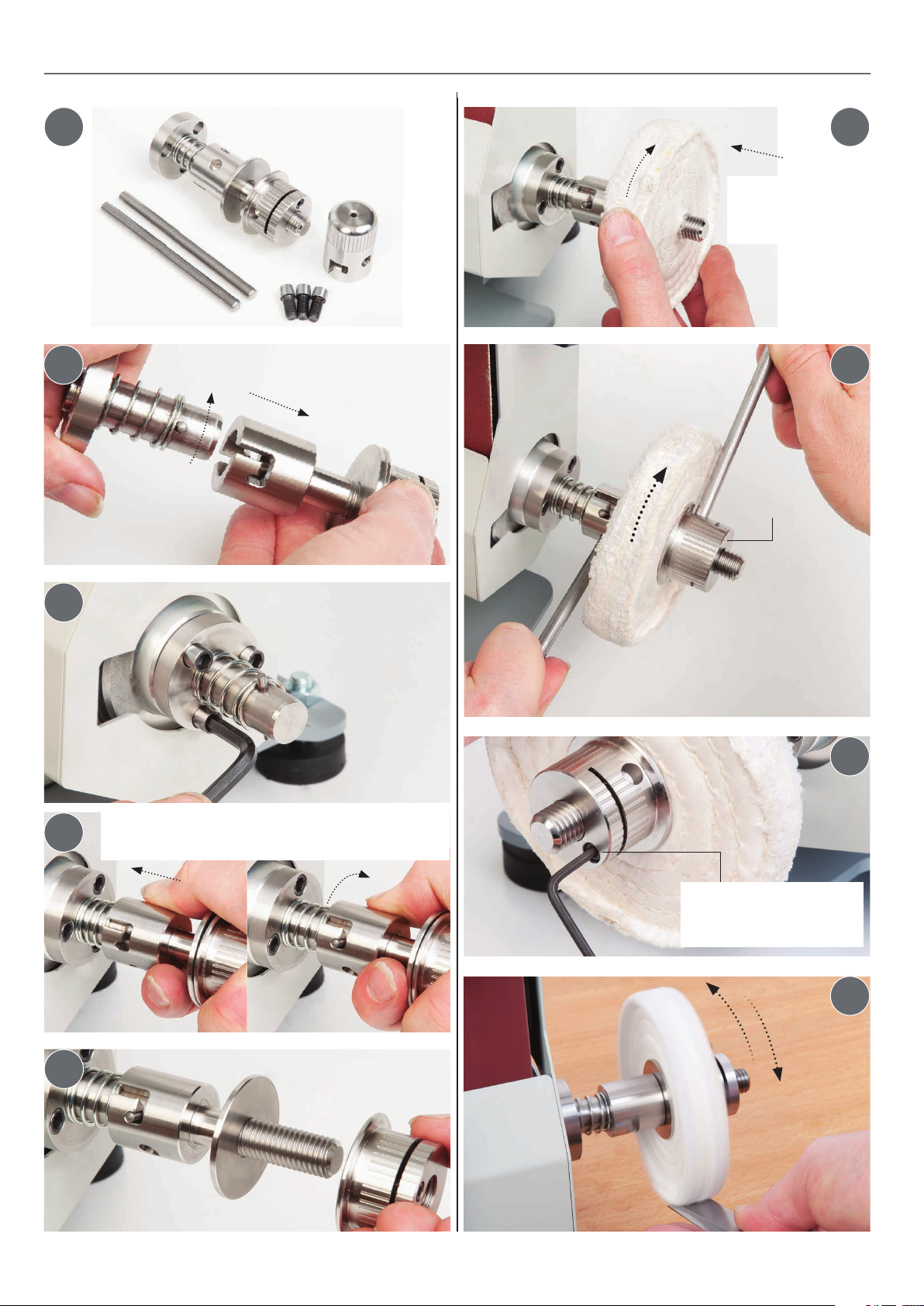
ULTIMATE EDGE ACCESSORIES
1 6
Screw on the
mop/honing wheel
(not supplied)
3
Detach assembly
Mount the carrier
using the three Hex
screws
72
Nut
Insert the tommy bars into
the holes in the “Twist & Fix”
assembly and tighten the
nut
8
Line up the bayonet fitting with the carrier pins, press
4
in and ‘Twist’ so the assembly is locked together
5
Nip-up the Hex screw
to prevent the nut from
unscrewing while in motion
9
20
Page 21
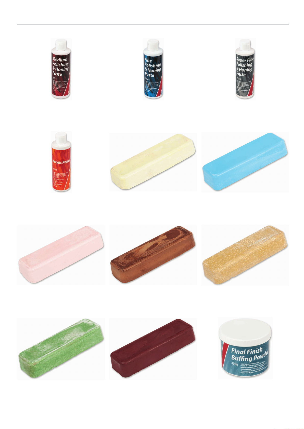
ULTIMATE EDGE ACCESSORIES
Red Medium Polishing
& Honing Paste 250g
Code 103703
Acrylic Polish
Code 105761
Blue Fine Polishing
Axminster Yellow Polishing Compound
& Honing Paste 250g
Code 103715
Axminster Blue Polishing Compound
Code 105921
White Super Fine
Polishing & Honing Paste 250g
Code 103716
Code 105924
Axminster Pink Polishing Compound
Code 105926
Axminster Green Polishing Compound
Code 105929
Axminster Brown Polishing Compound
Code 105927
Axminster Red Polishing Compound
Code 105930
21
Axminster Buff Polishing Compound
Code 105928
Axminster Trade Final Finish
Buffing Powder
Code 105763
Page 22
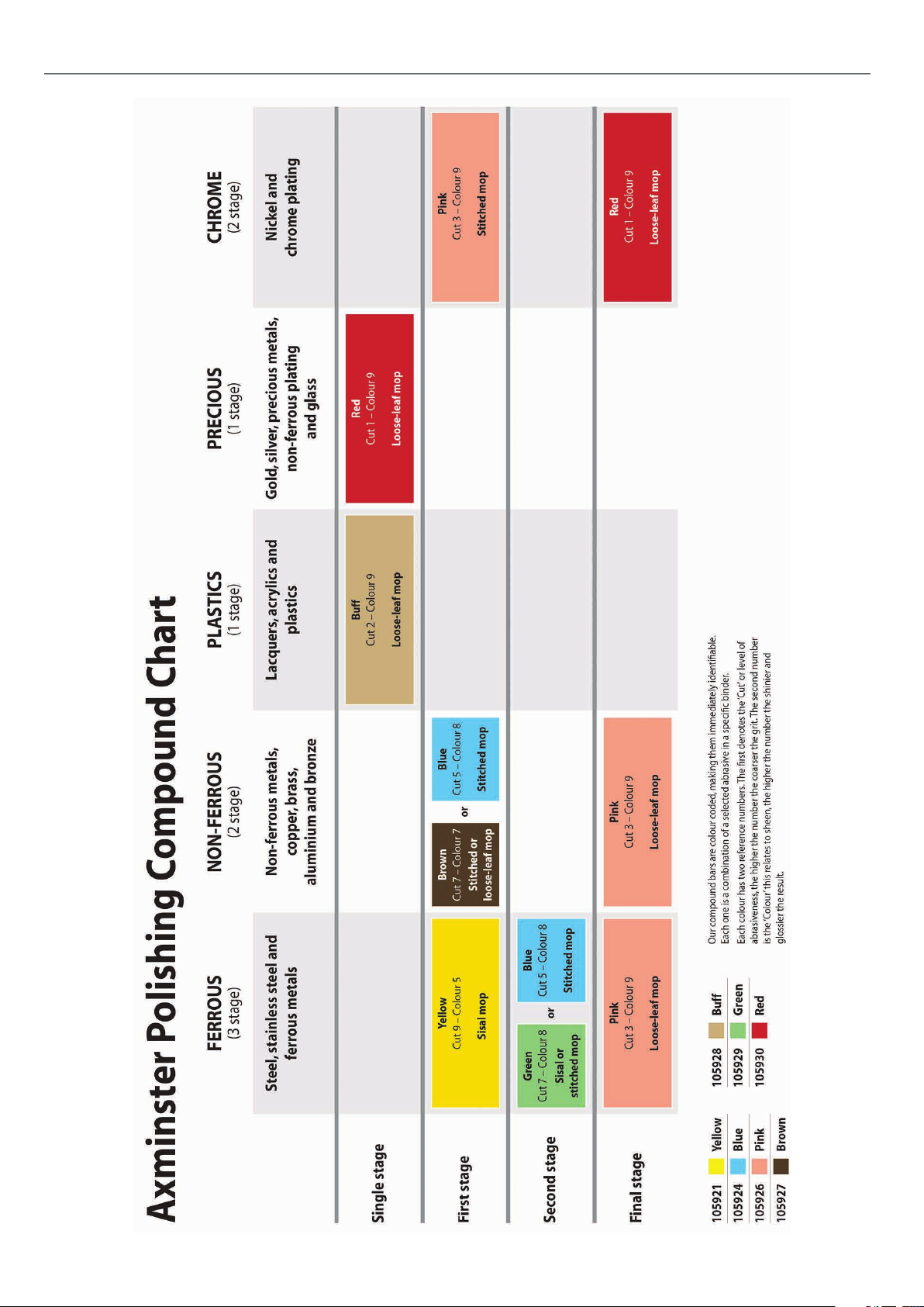
POLISHING COMPOUND CHART
22
Page 23
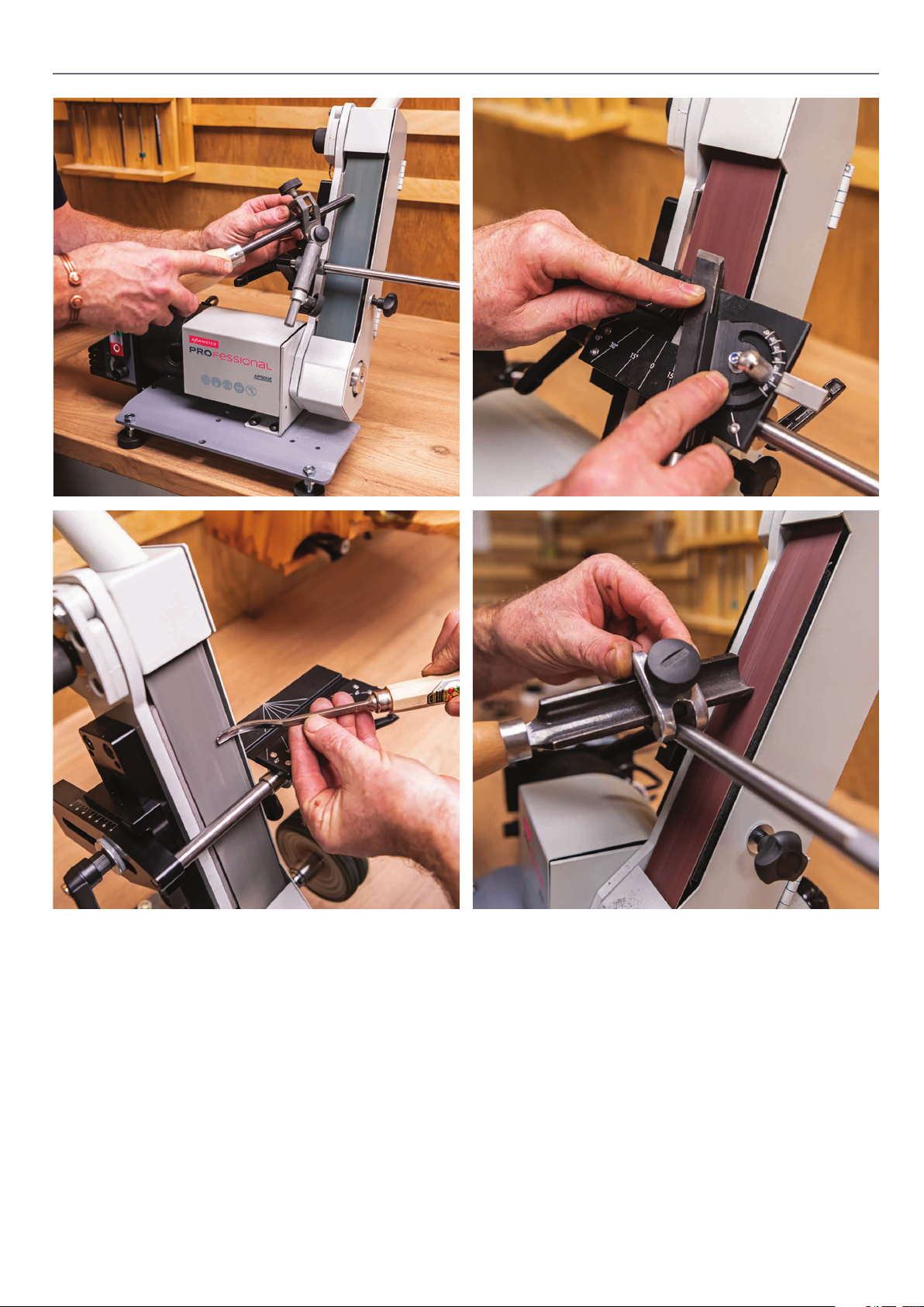
ULTIMATE EDGE ONLINE VIDEO
See the full range of accessories on our website including video guides
23
Page 24
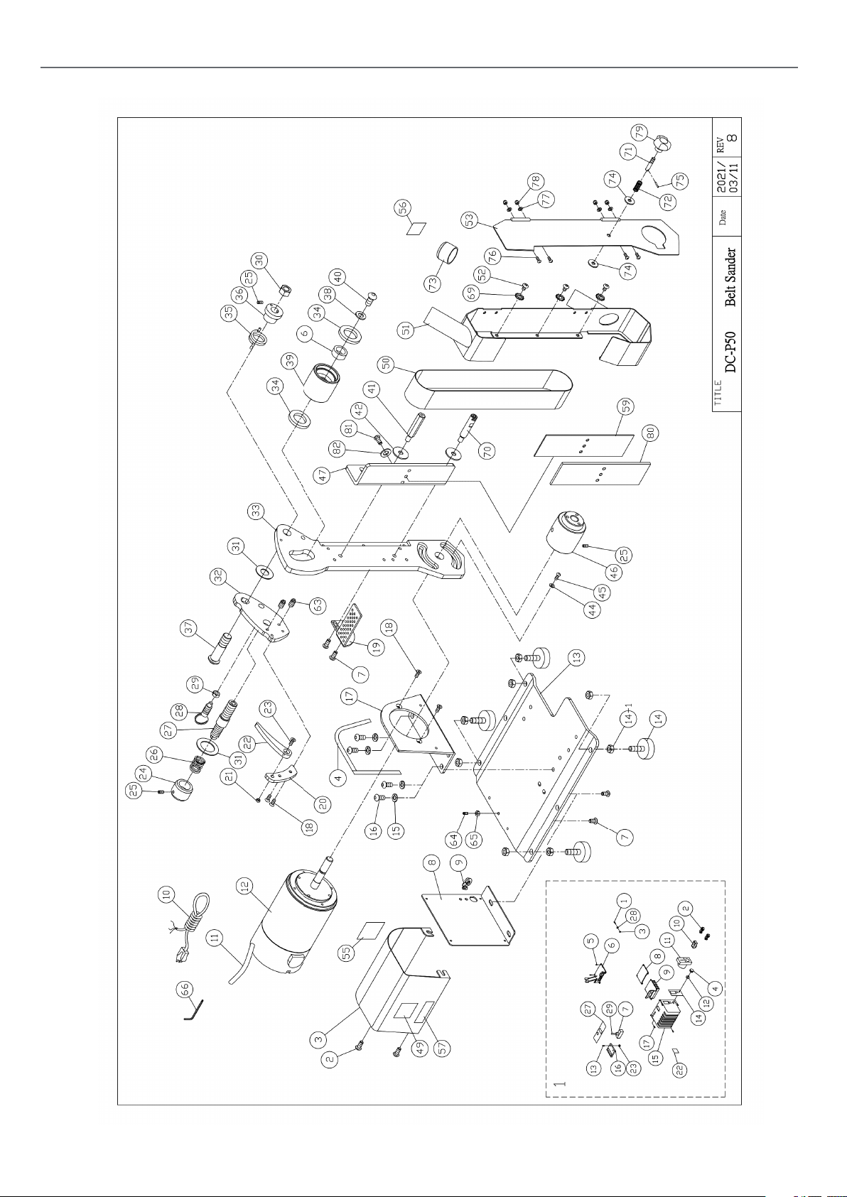
EXPLODED DIAGRAMSLIST
107658
AP50UE (Variable Speed)
24
Page 25

EXPLODED DIAGRAMSLIST
PART NO DESCRIPTION SPECIFICATION Qty
1 CONTROL BOX 1
l-l ROUND HEAD
SCREW
1-2 STRAIN RELIEF
BUSHING
1-3 NUT #10-24 2
1-4 VR KNOB 1
1-5 ROUND HEAD
SHEET METAL
SCREW
1-6 PC BOARD 1
1-7 FORREV
SWITCH
1-8 PARTITION
PLATE
1-9 HEAT SINK 1
1-10 POWER SWITCH 1
1-11 SWITCH 1
1-12 VR CONTROL 1
1-13 ROUND HEAD
SHEET METAL
SCREW
1-14 LABEL 1
1-15 CONTROL BOX 1
1-16 SPEED DISPLAY 1
1-17 ROUND HEAD
SCREW
1-22 LABEL 1
1-23 NUT M3 2
1-27 LABEL 1
1-28 TOOTH
WASHER
1-29 RUBBER
SLEEVE OF
SWITCH
2 BUTTORN
SCREW
3 COVER 1
4 FOAM PAD 1
6 BUSH 1
7 BUTTORN HEAD
SCREW
8 CONTROL BOX
PLATE
9 STRAIN RELIEF
BUSHING
10 POWER CORD 1
#10-24*5/16” 2
6P-4 2
M3X20MM 4
1
1
M3X15MM 2
#8-32*3/8 4
#10-24 2
1
M5X6 2
M6X12 4
1
SR-F51 1
11 MOTOR CORD 1
12 MOTOR 1
13 BASE PLATE 1
14 FOOT PAD 4
14A NUT 3/8” 8
15 SPRING
WASHER
16 BUTTON HEAD
SCREW
17 MOTOR PLATE 1
18 FLAT HEAD
SCREW
19 TOOL HOLDER 1
20 FIX PLATE 1
21 NYLON NUT M6 1
22 HANDLE 1
23 FLAT HEAD
SCREW
24 KNOB 1
25 SET SCREW M5Xl2 4
26 SPRING 1
27 SHAFT 1
28 LOCK PIN SET 1
29 NUT l/2”-13UNCX8t 1
30 NYLON NUT Ml 6x2. OP 1
31 BRASS WASHER 016X1.2t 2
32 LIVE PLATE 1
33 MAIN BODY 1
34 BEARING 6203ZZ 2
35 TWIST SPRING 1
36 BUSH 1
37 SHAFT 1
38 WASHER M10 1
39 LIVE WHEEL 1 1
40 BUTTON HEAD
SCREW
41 STOP ROD 1
42 WASHER M8 2
44 WASHER 1/4” 2
45 BUTTOM HEAD
SCREW
46 MOTOR WHEEL 1
47 HOLD PLATE 1
49 LABLE 1
50 BELT 1
M8X12 4
M5X12 4
M6x20 1
M10X15 1
1/4”xl” 2
4
25
Page 26
EXPLODED DIAGRAMSLIST
51 BODY COVER 3
52 ROUND HEAD
SCREW
53 SIDE COVER 1
55 MOTOR LABLE 1
56 I.D LABLE 1
57 WARNING
LABLE
59 GRAPHITE PAD 1
63 POM SET
SCREW
64 SET SCREW M6X15 1
65 NUT M6 1
66 LONG REACH
BALL END HEX
KEY
69 EXTERNAL
TOOTH
WASHER
M5X6 1
4mm 1
M5 3
70 STOP ROD 1
71 HANDLEBAR 1
72 SPRING 1
73 COVER 1
74 WASHER M6 2
75 PIN 02X12 1
1
2
76 BUTTOM
SCREW
77 WASHER M3 4
78 NYLON NUT M3 4
79 LOCK HANDLE 1
80 WEAR PLATE 1
81 BUTTOM HEAD
SCREW
82 WASHER 2
M3X10 4
M6x10 2
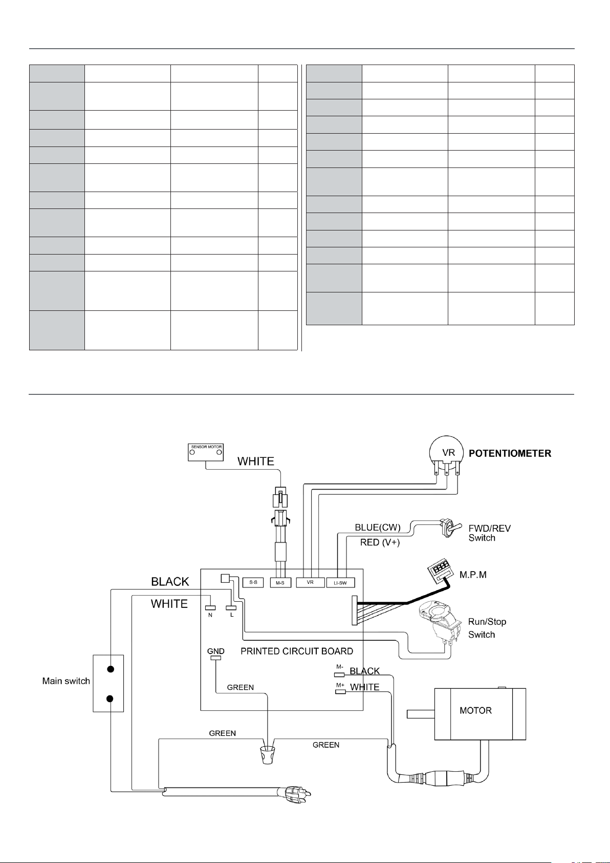
WIRING DIAGRAM
107658
AP50UE (Variable Speed)
26
Page 27
SPINDLE SPEED DIGITAL READOUT TROUBLESHOOTING
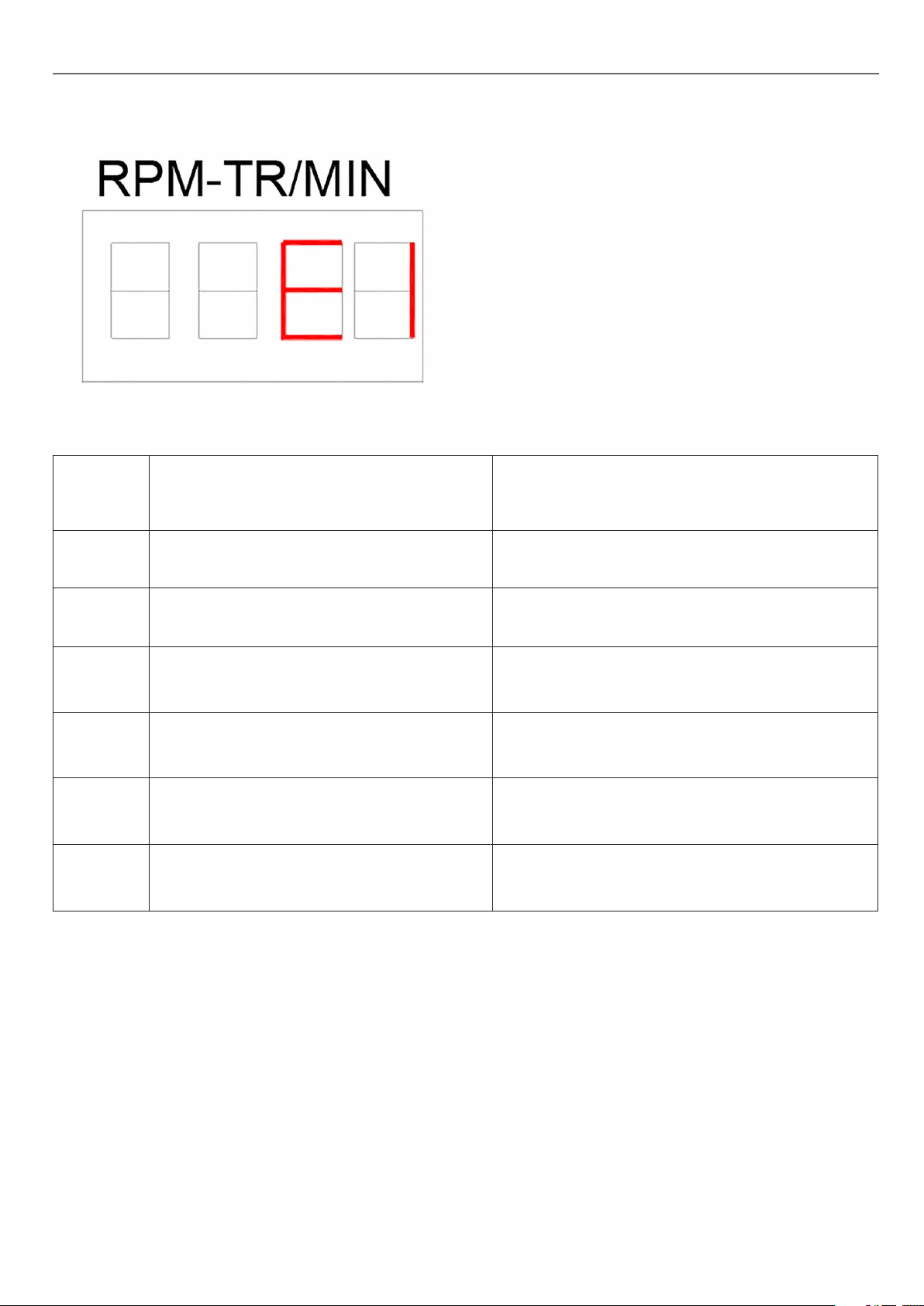
On occasions the spindle speed D.R.O may display error message
codes. If your machine stops unexpectedly and shows an error
code, look at the table below to determain what the code means
and how to resolve the issue.
ERROR
CODE
E1
E2
E3
E4
E7
E8
Description Solution
Machine is too hot
(motor will stop working.)
Machine is being overloaded
(motor will stop working.)
Problems with input voltage.(input
Unplug machine and leave machine
for 30 mins to cool down.
Press stop button to clear error code and
use machine more gently .
Check the power supply voltage is correct.
voltage could be too high or too low)
Machine is being overloaded ( motor will stop
working.)
Press stop button to clear error code
and retry.
Feedback from motor is not working. Press stop button to clear error code
and retry.
Control box issue. Contact supplier.
27
Page 28

The Axminster guarantee
Buy with confidence from Axminster!
So sure are we of the quality, we cover all parts and labour free of charge for three years!
For more information visit axminstertools.com/3years
The packaging is suitable for recycling.
Please dispose of it in a responsible manner.
EU Countries Only
Do not dispose of electric tools together with household waste material.
By law they must be collected and recycled separately.
Axminster Tools, Axminster Devon EX13 5PH
axminstertools.com
 Loading...