

Page 1
AT: 31/07/2025
BOOK VERSION: 10
Code 108995
Code 720773
Original Instructions
AP406WL
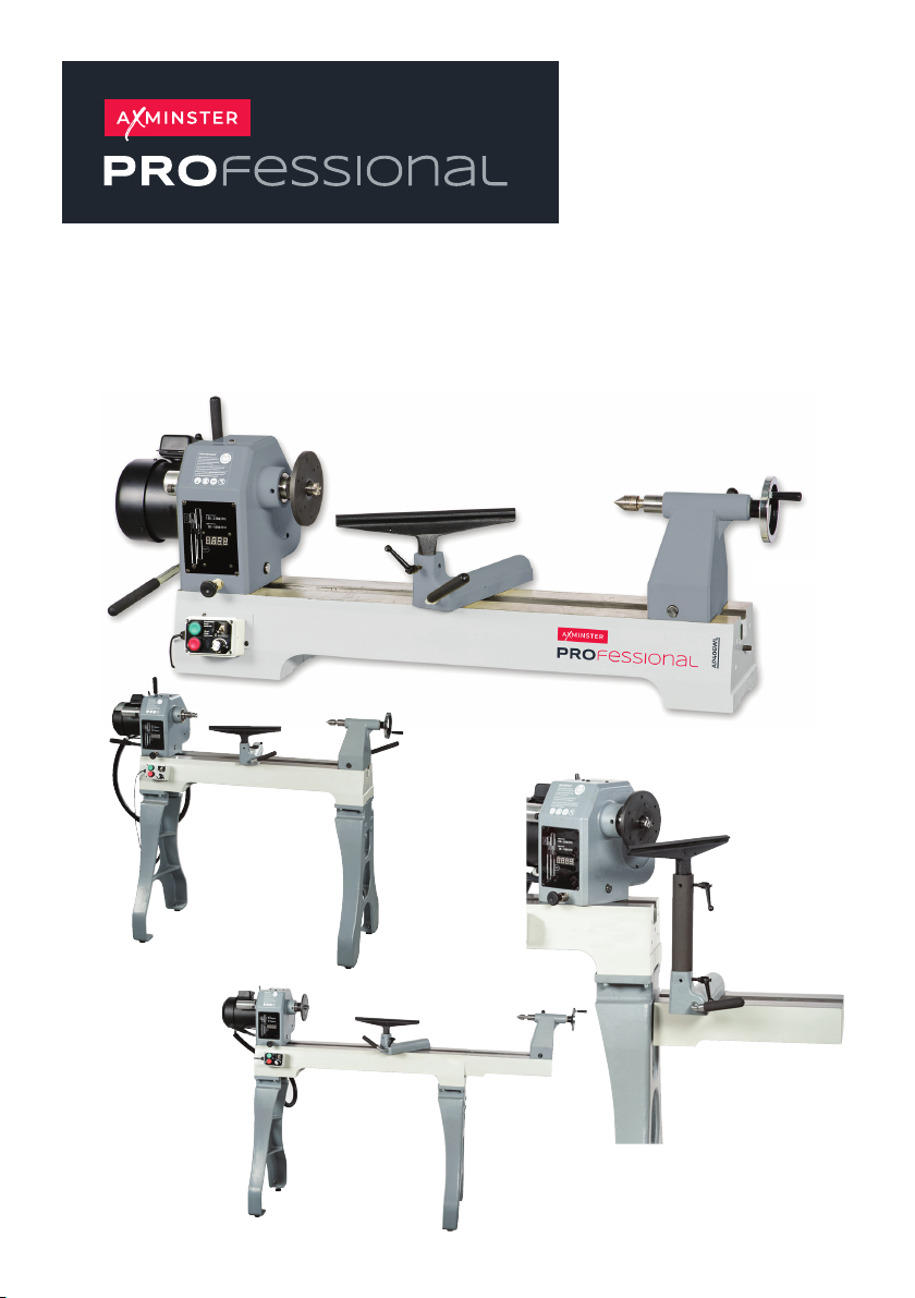
Bench Mounted Woodturning Lathe
Code 108995
Code 502704
Code 720773
Page 2
INDEX OF CONTENTS
EU Declaration of Conformity 02
What’s Included 03
Optional Accessories 03
General Instructions for 230V Machines 04
Specific Safety Instructions for Woodturning Lathes 05
Specifications 06
Assembly Instructions 6-10
Lathe Assembly 6-7
Lathe Stand Assembly 7-8
Lathe Extension Assembly 1 and 2 8-9
Illustration and Description 10-11
Operating Instructions 12-14
Rotating the Headstock 12
Removing the Faceplate 12
Indexing Facility 13
Removing the Drive Centre 13
Changing the Belt Speed 13-14
Optional Woodturning ASR Locking Ring 14
Maintenance 15
Exploded Diagrams/Lists 16-17-18-19-20-21-22
Wiring Diagram 23
EU DECLARATION OF CONFORMITY
The symbols below advise the correct safety procedures when using this machine.
Fully read manual
and safety instructions
before use
Ear protection
should be worn
Eye protection
should be worn
2
Dust mask
should be worn
HAZARD
Motor gets hot
Page 3
WHAT’S INCLUDED
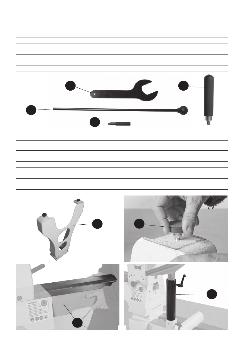
Quantity Item Part Model Number
1 No Bench Mounted Woodturning Lathe A
1 No Spanner B
1 No Push Rod C
1 No Spindle Lock Pin D
1 No Motor Plate Handle E
1 No Instruction Manual
AP406WL
B
E
C
D
OPTIONAL ACCESSORIES
Quantity Item Part Code Number
1 No Lathe Extension with Centring PIN H 502704
4 No 3/8” x 1 3/4” Hex Bolts & 8 No 3/8” Washers
1 No Tool Rest Extension I
2 No Lathe Stand F 502705
8 No 3/8" x 11/2" Bolts & 16 No 3/8" Washers
4 No Feet G
F
G
H
I
3
Page 4

GENERAL INSTRUCTIONS FOR 230V MACHINES
Good Working Practices/Safety
The following suggestions will enable you to observe
good working practices, keep yourself and fellow
workers safe and maintain your tools and equipment
in good working order.
WARNING!! KEEP TOOLS AND
EQUIPMENT OUT OF THE REACH
OF YOUNG CHILDREN
Primary Precautions
These machines are supplied with a moulded 13
Amp. Plug and 3 core power cable. Before using the
machine inspect the cable and the plug to make
sure that neither are damaged. If any damage is
visible, have the tool inspected/repaired by a suitably
qualified person. If it is necessary to replace the plug,
it is preferable to use an ‘unbreakable’ type that will
resist damage. Only use a 13 Amp plug, and make
sure the cable clamp is tightened securely. Fuse as
required. If extension leads are to be used, carry out
the same safety checks on them, and ensure that they
are correctly rated to safely supply the current that is
required for your machine.
Work Place/Environment
Make sure when the machine is placed that it sits
firmly on the bench or stand, that it does not rock,
that it is sufficiently clear of adjacent obstacles so
that you have unimpeded access to all parts of the
machine. The machine is designed for indoor use, do
not use when or where it is liable to get wet. Keep
the machine clean; it will enable you to more easily
see any damage that may have occurred. Clean the
overall machine with a damp soapy cloth if needs
be, do not use any solvents or cleaners, as these may
cause damage to any plastic parts or to the electrical
components. Clean the machine components with
a lightly oiled cloth. If the machine is liable to be
standing idle for any length of time a light coat of
machine or spray oil will minimise rusting.
It is good practice to leave the machine unplugged
until work is about to commence, also make sure
to unplug the machine when it is not in use, or
unattended. Always disconnect by pulling on the
plug body and not the cable. Once you are ready to
commence work, remove all tools used in the
setting operations and place safely out of the way.
Re-connect the machine.
Carry out a final “tightness” check e.g. chuck or face
plate, workpiece, tool rest, etc., check that the
correct speed has been selected.
Make sure you are comfortable before you start
work, balanced, not reaching etc. If the work you are
carrying out is liable to generate flying grit, dust or
chips, wear the appropriate safety clothing, goggles,
gloves, masks etc. If the work operation appears
to be excessively noisy, wear ear-defenders. If you
wear your hair in a long style, wearing a cap, safety
helmet, hairnet, even a sweatband, will minimise
the possibility of your hair being caught up in the
rotating parts of the tool, likewise, consideration
should be given to the removal of rings and
wristwatches, if these are liable to be a ‘snag’ hazard.
Consideration should also be given to non-slip
footwear, etc.
DO NOT work with cutting tools of any description if
you are tired, your attention is wandering or you
are being subjected to distraction. A deep cut, a
lost fingertip or worse; is not worth it! Above all,
OBSERVE…. make sure you know what is happening
around you, and USE YOUR COMMON SENSE.
Keep the work area as uncluttered as is practical, this includes personnel as well as material.
Under no circumstances should CHILDREN be
allowed in work areas.
4
Page 5

SPECIFIC SAFETY INSTRUCTIONS FOR WOODTURNING LATHES
1. Do not use ‘split’ work pieces.
2. Always start at the lowest speed when starting a
new task.
3. Check that the tool rest is at or slightly below the
centre line of the workpiece.
4. Check the workpiece is securely mounted in the
lathe before switching on the power.
5. Rotate the workpiece by hand, to check that it
is centralised, clear of the tool rest, not ‘split’ or has
loose knots.
6. Where lathes have the facility to be reversed; check
the machine is rotating in the correct direction.
7. If your lathe has the facility to run in reverse, you
must ensure that the mounting accessories (chucks,
faceplates etc.,) can be ‘locked’ onto the lathe
mandrel, and in the case of chucks have some form
of security device to prevent them ‘unwinding’ during
reverse operation.
8. Make sure your tools are stored/racked away from
the turning area of the lathe. Do not reach over a
rotating workpiece at any time.
9. Do not ‘dig in’ or try to take too large a cut.
10. Do not leave the lathe running unattended; or
leave the machine until everything is stopped.
11. Some turning tools may have specific sharpening
angles that have been determined by the
manufacturers; when re-sharpening, adhere to these
angles to maximise the finish of your work.
SPECIFICATION
Code 108995
Model AP406WL
Rating Professional
Power 230V 50Hz 1.5kW
Speed Low 0-1,600rpm High 300-3,750rpm
Spindle Taper MT2
Spindle Thread with ASR Safety Groove M33x3.5 mm (Ref T38)
Taper Tailstock MT2
Distance Between Centres 700 mm
Max Diameter Over Bed 203 mm
Overall L x W x H 1115 x 450 x 460 mm
Weight 96 kg
5
Page 6
ASSEMBLY INSTRUCTIONS
Please take some time to read the section entitled
“Illustration and Description” to identify the
various parts of your machine so that you are familiar
with the terminology we will use to enable you
to set up and operate your table lathe safely and
correctly.
The lathe and its accessories will arrive coated with
corrosion preventative grease. This will need to
be cleaned from the lathe, its components and
accessories prior to it being set up.
Use degreaser to remove the barrier grease. Be
warned, it will stain if you splash it on clothing etc.,
wear overalls, rubber gloves are also a good idea,
as is eye protection. After cleaning, lightly coat the
machine with a thin layer of light wax. If you used
paraffin/kerosene make sure you apply this thin film
sooner rather than later.
WARNING: The wood lathe is a heavy machine, it is advisable to use a lifting
device such as a hoist, scissor lift or seek help when assembling the lathe.
Unpack your new 1628 Variable Speed Lathe and recycle the packaging responsibly.
The cardboard packaging is biodegradable.
Lathe Assembly
The majority of the machine comes fully assembled, the remaining items to be assembled is described below.
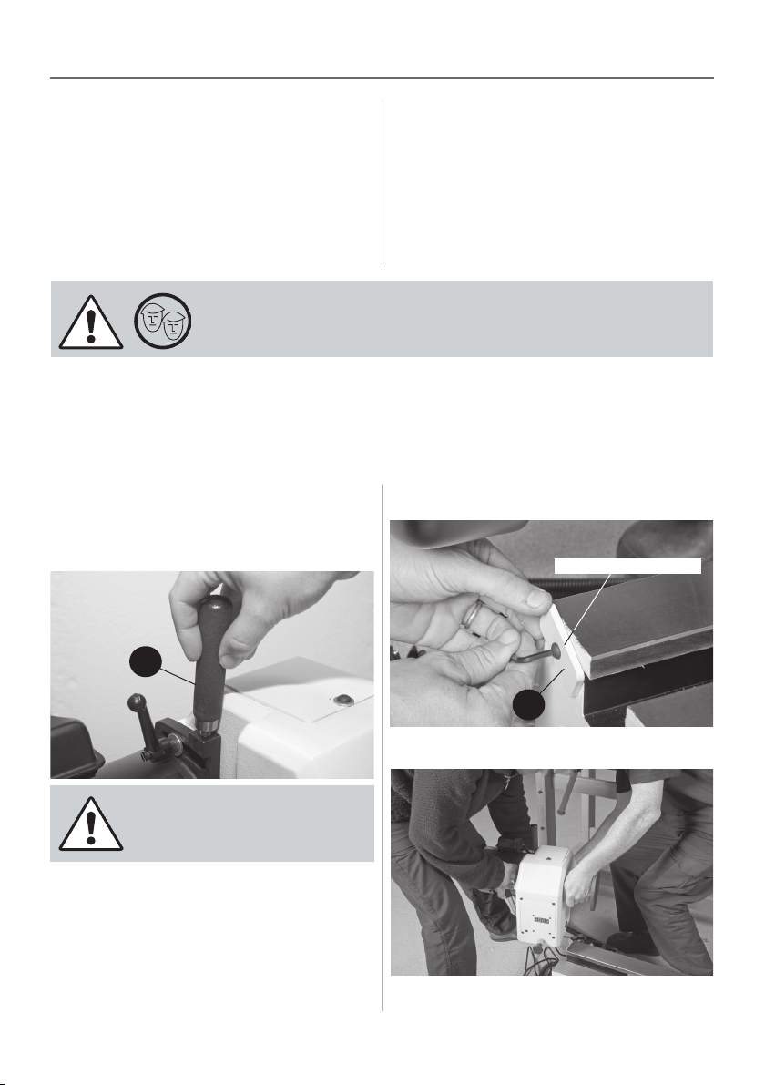
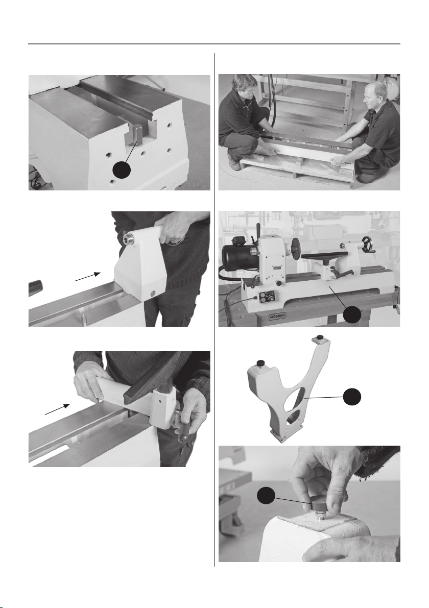
Locate the motor plate handle (E) and screw it into
the pre-drilled hole in the motor tension bracket, see
figure 1
Figure 01
Headstock stop bracket
Figure 02
E
We recommend you remove the headstock, tool
rest and tailstock from the lathe bed before
lifting the lathe assembly off the pallet as the
lathe is very heavy.
1. Loosen the headstock stop bracket (a), to the
left side of the lathe bed and with help slide the
headstock off the lathe bed and place safely aside,
see figures 2-3.
2. Remove the tailstock stop rod (b) from the right
hand side of the lathe bed and remove both the
tailstock and tool rest assembly and place safely
aside. (See figures 4-5-6)
a
Figure 03
Remove the headstock from the lathe bed
6
Page 7
ASSEMBLY INSTRUCTIONS
Figure 04
Figure 05
Figure 06
Figure 07
b
Figure 08
A
Figure 09
3. Lift the lathe bed from the pallet onto a work
bench, see figs 7 then refit the headstock, tool rest
and tailstock as described in steps 1 and 2, see
figure 8
Lathe Stand Assembly
1). Locate the two lathe stands (F) and the four feet
(G).Screw the threaded feet into the pre-drilled holes
to the base of the stands. (See figure 9)
F
G
7
Continues Over...
Page 8
ASSEMBLY INSTRUCTIONS
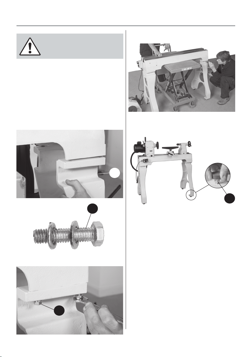
Remove the headstock, tool rest assembly and
tailstock from the lathe bed as before to make
it easier to assemble the stands
2. After removing the above lift the lathe bed using a
scissor lift, lifting host or seeking help.
3. Place the stands (F) to each end of the lathe bed
and line up the holes in the stands with threaded
holes in the lathe bed, secure using the 3/8" bolts and
washer (c),see figures 10-11-12-13.
4. Replace the headstock, tool rest and tailstock. (See
figure 14)
Figure 10
F
Figure 11
c
Figure 13
Use a lifting device as a scissor lift for example to raise the
lathe bed to mount the lathe stands
Figure 14
G
Adjust the feet (G) until the lathe is level
Figure 12
Lathe Extension Assembly
The lathe extension (H) bolts onto either end of the
lathe bed which increases the length of the lathe for
turning larger projects. The lathe extension can also
be mounted to the stands for turning large diameter
projects.
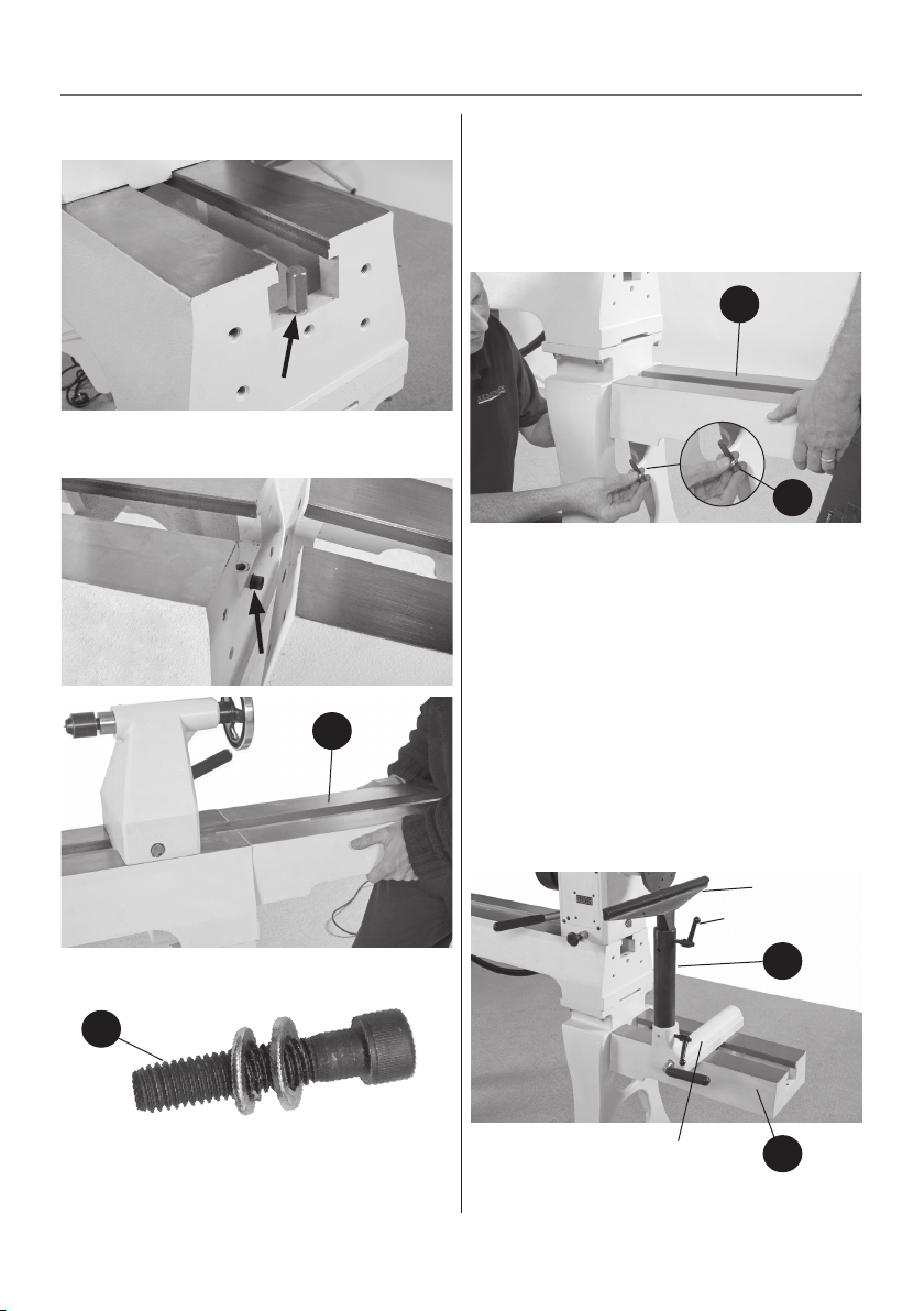
Assembly 1
1. Locate the lathe extension and centring PIN (H)
and 3/8” Hex bolts, washers (d). Remove the tailstock
stop ROD from the end of the lathe bed, see figure
15 and place safely aside.
2. Insert the centring “PIN” for the lathe bed
c
extension into the centre hole in the main lathe bed.
Slot the centre hole in the bed extension over the
“PIN” and upagainst the lathe bed, see figure 16. Line
up the holes and secure using the 3/8” Hex bolts and
washers (d), See figure 17.
8
Page 9
ASSEMBLY INSTRUCTIONS
Figure 15
Remove the tailstock stop “ROD” and place safely aside
Figure 16
H
Assembly 2
1. Line up the holes in the lathe extension (H) with
the threaded holes in lathe stand (F) and secure
using the 3/8” Hex bolts and washers (d), see figure
18.
Figure 18
H
d
Using the 3/8” Hex bolts and washers (d), secure the lathe
extension in position
2. Release the headstock lock and slide the headstock
down to the end of the lathe bed and lock in position.
Slide the tool rest assembly onto the lathe extension
(H), undo the tool rest locking handle and remove
tool rest. Locate the tool rest extension (I), slot the
tool rest extension into the machined recess and
tighten the clamping handle.
3. Loosen the clamping handles on the tool rest
extension (I) and slot the tool rest into the extension,
tighten the tool rest locking handle. (See figure 19)
While holding the lathe bed extension (H), secure using
the four the 3/8” Hex bolts and washers (d)
d
Figure 19
Tool rest
Tool rest lock
I
Tool rest assembly
9
H
Page 10
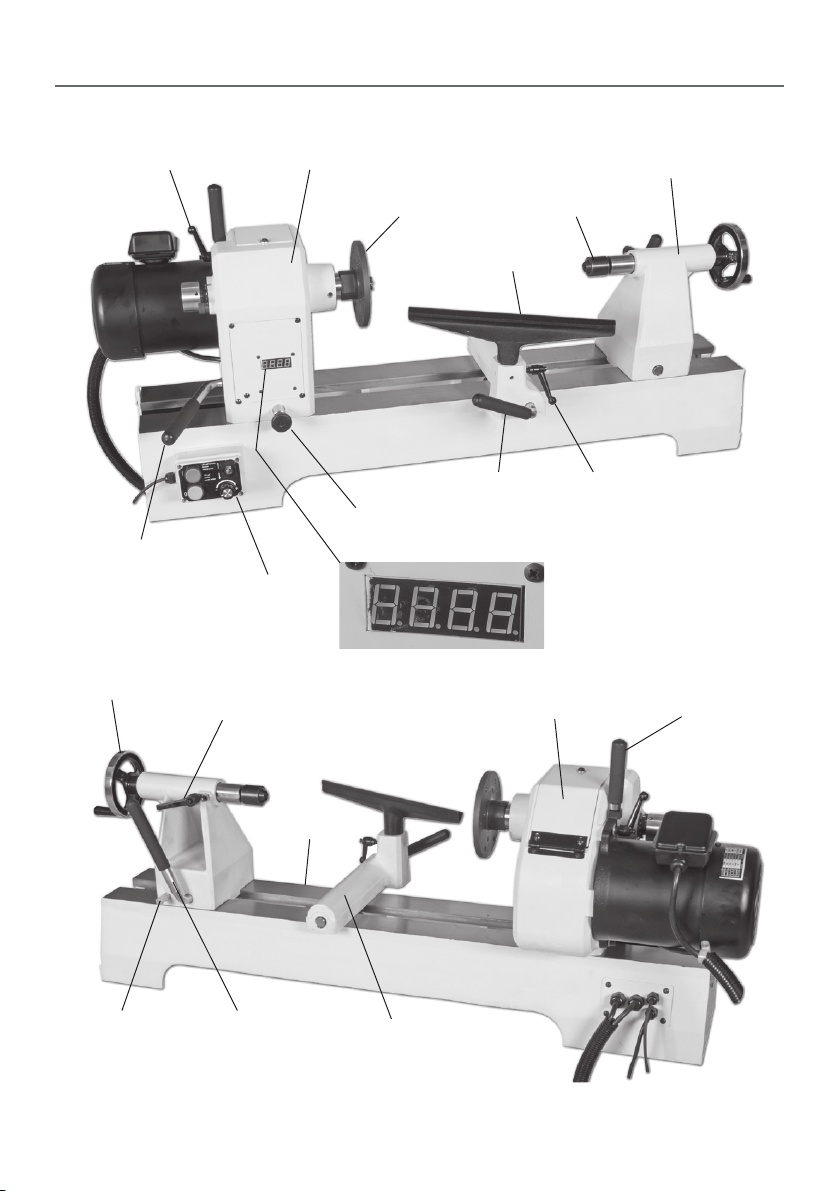
ILLUSTRATION AND DESCRIPTION
Motor locking handle
Headstock locking handle
Tailstock wheel
Tailstock barrel lock
Headstock
Control box
Faceplate
Banjo lock
Headstock pivot lock
Spindle speed LED
Tool rest
Access panel
Tailstock
Live centre
Tool rest lock
Motor plate handle
Lathe bed
Tailstock lockTailstock lock stop
Banjo
10
Page 11
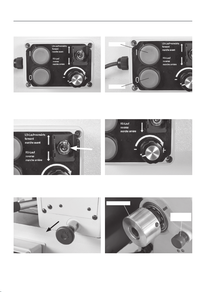
ILLUSTRATION AND DESCRIPTION
ON
OFF
The control box has a magnetic base enabling it to be
positioned anywhere on the lathe
Forward and Reverse switch The Speed Control Knob, enables you to increase
ON (Green) and OFF (Red) buttons
or decrease the speed of the spindle
Indexing ring
Index lock
pin
Headstock Pivot Lock, pull this knob to rotate the headstock to
the desired position
Indexing ring facility and locking pin is used for fluted columns,
clock faces and accurate hole positioning
11
Page 12
OPERATING INSTRUCTIONS
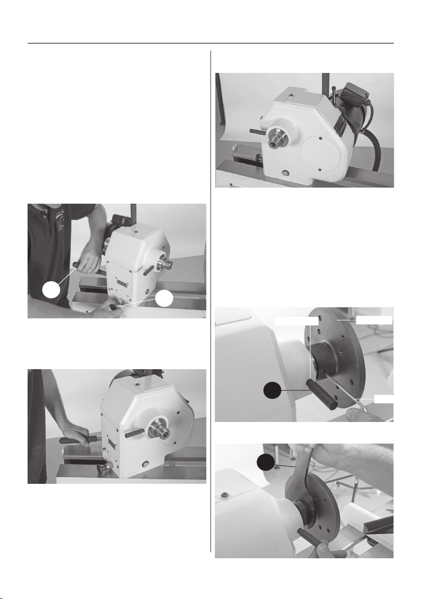
Rotating the Headstock
The Headstock can be swivelled in any position
by lifting up the Headstock locking handle (a) and
pulling the Headstock pivot lock (b) out, swivel the
Headstock to the desired position is reached, lock in
place by pushing down the headstock locking
handle (a). (See figure 18)
The Headstock incorporates two index positions
45˚and 90˚, swivel the headstock until it locks in
place to allow bowls to be turned in front of the
lathe. (See figures 19-20)
Figure 18
a
b
Lift up the Headstock locking handle (a), pull the
Headstock pivot lock (b) out and swivel the
Headstock to the desired position
Figure 19
Figure 20
The Headstock locked in the 90˚ index position
Removing the faceplate
Locate the spindle lock pin (D) and spanner (B).
Rotate the spindle until the machined hole on the
shaft lines up with the spindle collar access hole.
Insert the locking pin (D) to lock the spindle, using
a Hex key loosen the two grub screws on either side
of the spindle, see figure 21. Using the spanner (B)
remove the faceplate, see figure 22.
Figure 21
Access hole
Faceplate
The Headstock locked in the 45˚ index position
D
Hex key
Figure 22
B
12
Page 13
OPERATING INSTRUCTIONS
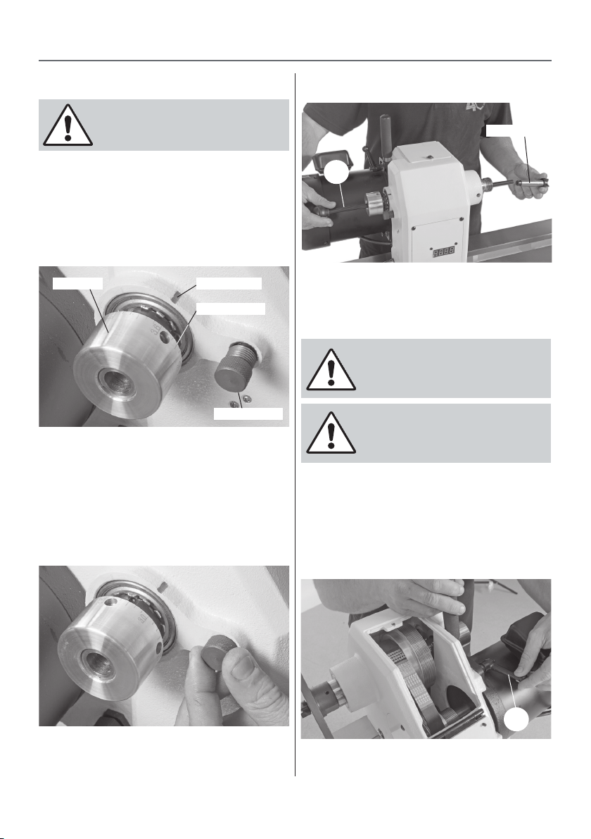
Indexing facility
DISCONNECT THE LATHE FROM THE
MAINS SUPPLY
The Indexing ring is situated to the left side of the
headstock which incorporates 36 positions at (10˚)
segments. To the side of index ring is the index
locking pin to lock the spindle in position. The
indexing facility is useful for fluted columns, clock
faces and accurate hole positioning. (See figure 23)
Figure 23
Index ring
Line up the measurement you require on the index
ring with the index marker on the headstock and
screw in the index locking pin to lock the spindle in
position. (See figure 24)
NOTE: Make sure the measurement is in line with
the index marker otherwise the locking pin may
not in gauge properly.
Index marker
10˚ Segments
Index lock pin
Figure 24
Figure 25
Drive centre
C
Repeat the procedure for the live centre in the
tailstock.
Changing the belt speed
Note: The lowest speed pulley combination
is furthest from the faceplate, the smallest
motor pulley diameter to largest spindle pulley
diameter.
DISCONNECT THE LATHE FROM THE
MAINS SUPPLY BEFORE CHANGING
THE BELT
Open up the pulley access panel on top of the
headstock by removing the Hex screw. Slacken the
belt by loosening the motor locking handle (a),
move the motor until the belt is slack enough to be
reposition. (See figure 26)
Figure 26
Removing the Drive Centre
To remove the drive centre from the spindle, locate
the push rod (C), insert it through the index ring
assembly and push the drive centre out, see figure 25.
Loosen the motor locking handle (a) enough
to allow the pulley to be repositioned
13
a
Continues Over...
Page 14
OPERATING INSTRUCTIONS
Figure 27
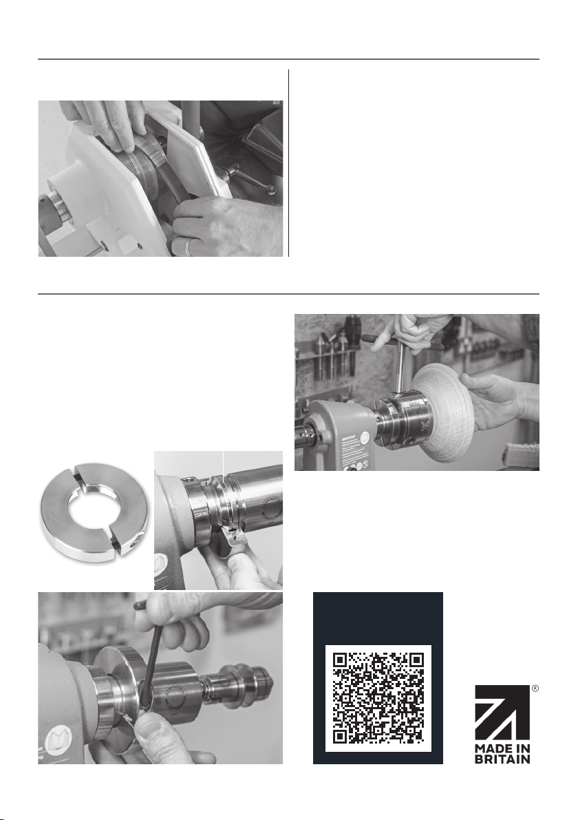
Reposition the belt, making sure the groves in the
belt slot into the groves in the pulleys. Pull/push
the motor assembly until the belt is under tension,
retighten the motor locking handle (a). (See figure
27)
Close the pulley access panel and replace the Hex
screw.
OPTIONAL WOODTURNING ASR LOCKING RING
Added level of safety
The Axminster Woodturning ASR Locking Ring is
designed for lathes with a M33x3.5 EURO standard
(ASR) spindle and threaded fittings that feature a
EURO locking ring groove. When the lathe runs in
reverse or stops, the precision engineered tool
prevents threaded fittings such as chucks or
faceplates from becoming loose.
Euro locking ring groove
See the online Video by scanning the Q&R code below.
Watch the set up
video here
14
Page 15
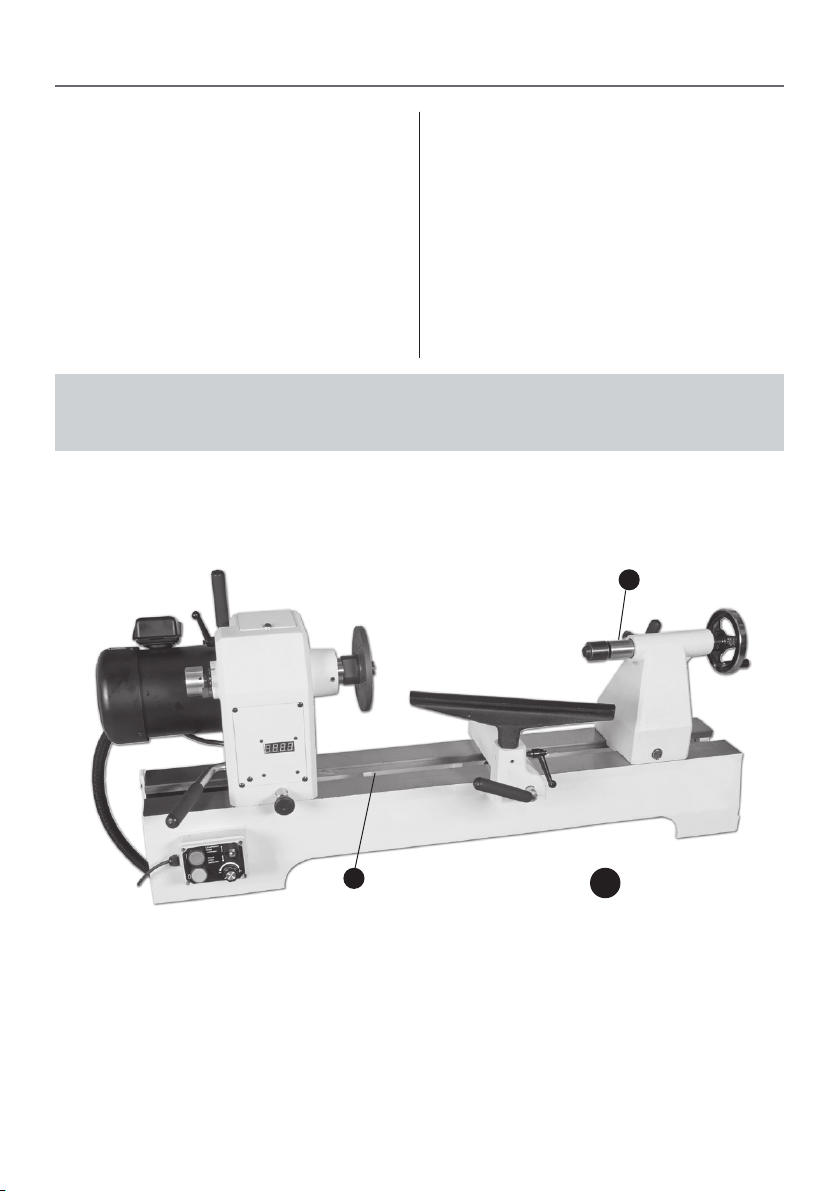
MAINTENANCE
The woodturning lathe has little maintenance, but
it is advised to do the following checks to keep the
lathe in good working order.
After every use
• Clean wood shavings away from the lathe bed and
tool rest
• Smear a light coat of wax (Protec Tool Wax Polish,
Code. 211835) over the lathe bed to allow the Banjo
and Tailstock to run smoothly over the lathe bed and
to prevent corrosion.
Monthly check
• Check the tension of the belt and adjust, see
previous page for changing the belt speed.
• Check any build up of wood shaving on the motor
and spindle pulley’s and clean if necessarily.
• Using a airline, blow out the motor’s air vents.
NOTE: Always use a dust mask and eye protection
NOTE: If the lathe not going to be used for a period of time, smear a light coat
of wax over the lathe bed and place a dust sheet over the lathe.
Wax Points
15
Page 16
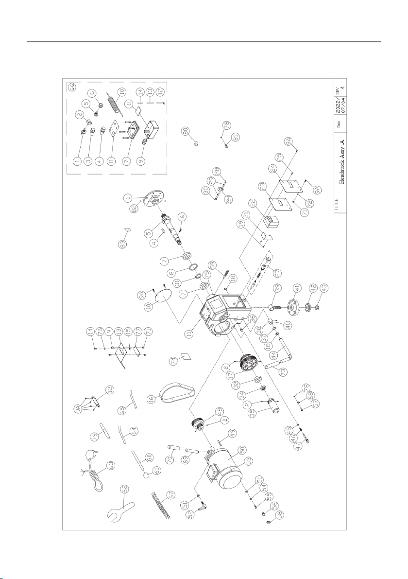
EXPLODED DIAGRAMS/LISTS
Headstock Assembly A
16
Page 17

Headstock Assembly A
EXPLODED DIAGRAMS/LISTS
PART
NO.
1628-A01 Face plate 6” 1
1628-A02 Set Screw 1/4*3/8” 6
1628-A04 Key 8*8*40 1
1628-A05 Spindel M33*P3.5 1
1628-A06 Round Head
1628-A07 Bearing 6007ZZ 2
1628-A08 bearing
1628-A09 Big Round
1628A09A
1628-A10 Cover 1
1628-A11 Headstock 1
1628-A12 Latter Niu 1
1628-A13 Belt Cover 1
1628-A14 Screw 1/4x1/2 1
1628-A15 Nut CSTW-5 1
1628-A16 Belt 220J-10 1
1628-A17 Spindle Pully 1
1628-A18 C ring S-19 2
1628-A19 Tap Screw 1/4x1/2 2
1628-A21 Cover Plate 1
1628-A22 Digital Read-
1628-A23 Control Plate 1
1628-A24 Control Panel
1628-A25 Tap Screw M3*10 4
1628-A27 Postion Set 1
1628-A28 Nylo Nut M3 2
DESCRIPTION SPECIFICA-
Screw
bush-big
Head Screw
Truss Head
Screw
out
Acrylic
TION
1/4”*5/16” 4
#1024unc*1/2”
#1024unc*3/8”
Q’ty
1628-A29 Washer M3 4
1628-A30 Round Head
1628-A31 Bearing
1628-A32 Bearing 6205ZZ 1
1628-A34 Nylon Nut M25xP1.5 1
1628-A35 Hand Wheel 1
1628-A36 Cord
1
1628-A37 Wave Washer BWW-629 1
1628-A38 Bush 1
2
1628-A39 Bolt 1
1628-A40 Set Screw 1 /4”*1/4 ” 2
11
1628-A41 Headstock
1628-A42 Fixing Piece 1
1628-A43 Nylo Nut 3/4”-10unc 1
1628-A44 Headstock
1628-A45 C-ring S-9 1
1628-A46 Spring 1
1628-A47 Lock Pin 1
1628-A48 Motor Pully 1
1628-A49 Key 6*6*55 1
1628-A50 Motor 230V 50HZ 1
1628-A51 Washer 3/8” 2
1
1628-A52 Handle 3/8” 1
1628-A53 Motor Label 1
1628-A54 Spring
1
1628-A55 Cap Screw 3/8-16uncx1-
1628-A56 Cord Protec-
Screw
Bush-small
Protector
Base
Shaft
Washer
tor
M3*35 2
1
MGB20-10B 1
1
1
3/8” 1
1
1/4
PG13.5 1
17
Continues Over...
Page 18

MAIN HEADING
Headstock Assembly A
1628-A57 Screw #10-24*7/8” 1
1628-A58 Wire Fixing
1628-A59 Lock Pin 1
1628-A60 Tapered
1628-A61 Knob 1
1628-A62 Faceplate
1628-A63 Power Wire 1
1628-A64 Power Wire-2 1
1628-A65 Motor Wire 1
1628-A66 Control Box 1
1628A66-1
1628-
A66-2
1628-
A66-3
1628-
A66-4
1628-
A66-5
1628-
A66-6
1628-
A66-7
1628-
A66-8
1628-
A66-9
1628-A66-10Single Wire 1
Piece
Shaft
Wrench
Fed/Rev
Switch
Protector 1
Switch-Green 1
Switch-Red 1
VR Control 1
VR Nut 1
Box 1
Magnet 1
Cord
Protector
5/8” 4
PG11 1
1628-A66-12Wire 1 1
1628-A66-13Wire 2 1
1628-A66-14Wire 3 3
1
1628-A67 Hose 1
1628-A68 Wire Fixing
1
1628-A69 Handle 1
1628-A70 Protect
1628-A71 Nylon Nut #10-24 3
1628-A72 Tooth
1
1628-A73 Protect
1628-A74 Label 1
1628-A75 Warning
1628-A76 Washer 1/4” 1
1628-A77 Acrylic 1
1628-A78 Nut #10-24 2
1628-A79 Double
1628-A80 Nylon Screw
1628-A81 Truss Head
1628-A82 Set Screw M6x10 2
1628-A83 Warning
Piece
Slipcover
Washer
Slipcover
Label
Taper
Plugs
Screw
Label
ACC2.5 1
19-100 1
#10-24 1
19-140 1
#10-24*1/2” 1
1
1
1
1
1628-
A66-11
Control Label 1
18
Page 19
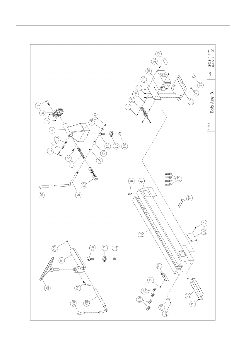
Body Assembly B
MAIN HEADING
19
Continues Over...
Page 20

EXPLODED DIAGRAMS/LISTS
Body Assembly B
PART
NO.
1628-B01 Handle 1
1628-B02 Handwheel 5”*19 1
1628-B03 Set screw 1/4* 1/4 2
1628-B04 Tailstock 1
1628-B05 Handle 5/16” 1
1628-B06 Eccentric
1628-B07 Big Round
1628-B08 stop rod 2
1628-B09 Set screw M10x30 1
1628-B10 nut M10 1
1628-B12 Tailstock
1628-B13 Tailstock
1628-B14 C ring S-19 2
1628-B15 Bushing 1
1628-B16 Bolt 2
1628-B17 Fixing Piece 2
1628-B18 Nylon nut 3/4”-10unc 2
1628-B19 Bed 1
1628-B20 Eccentric
1628-B21 Toolrest
1628-B22 Tool rest 14” 1
1628-B23 C ring S-18 1
1628-B24 Lever 3/8” 1
1628-B25 Cover 1
DESCRIPTION SPECIFICA-
shaft
Head Screw
Spindle
Screw
shaft
Carriage
TION
#1024unc*3/8”
3/4”-16UNF 1
Q’ty
1628-B26 cord
1628-B27 Dust board 1
1628-B28 Front cover 1
1628-B29 inverter side
1628-B30 inverter 1
1628-B31 Big Round
1
13
1628-B32 inverter
1628-B33 Flat head
1628-B34 Warning
1628-B35 cord
1
1628-B36 Round Head
1628-B37 Cable tie 2
1628-B38 protect slip-
1628-B39 guard 1
1628-B40 protect slip-
1628-B41 Name plate 1
1628-B42 Hex head
1
1628-B43 Warning
1
1628-B44 wave washer BBW-629 1
1628-B45 brake 1
1628-B46 Nut #10-24UNC 2
protector
cover
Head Screw
backplane
screw
Label
protector
Screw
cover
cover
screw
Label
PG11 2
#1024unc*3/4”
#1024unc*5/16”
PG9 2
1/4”20UNC*1/2”
17-100 1
19-140 1
3/8”*2” 4
1
4
1
4
1
1
1
20
Page 21
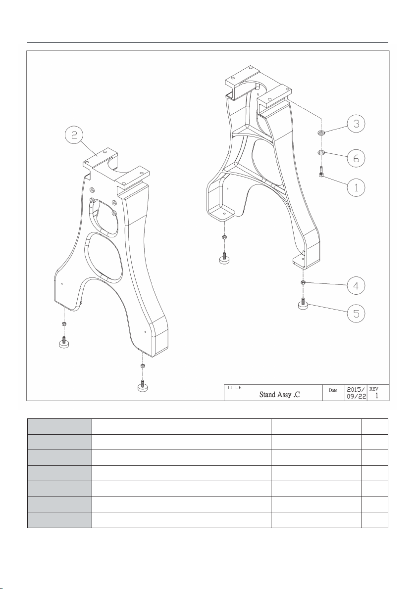
Stand Assembly C
EXPLODED DIAGRAMS/LISTS
PART NO. DESCRIPTION SPECIFICATION Q’ty
1628-C01 Hex Head Screw 3/8”-16*1-1/2 8
1628-C02 Stand 22” 2
1628-C03 Washer 3/8”-18*2t 8
1628-C04 Nut 3/8” 4
1628-C05 Adjustable Leveler 3/8” 4
1628-C06 spring washer 3/8” 8
21
Page 22
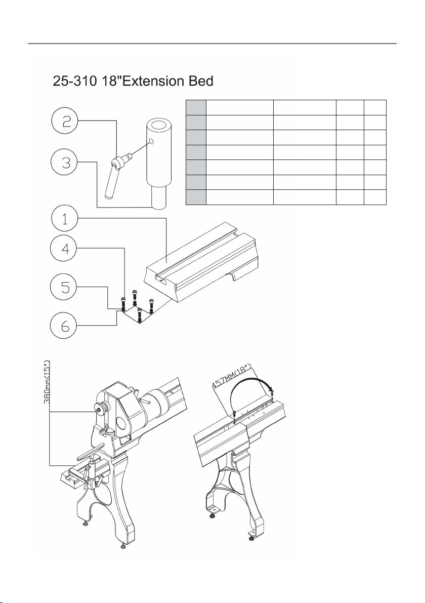
EXPLODED DIAGRAMS/LISTS
No. Part No. Description Size Qty
1 25-618 Extension bed 18” 1
2 25650-30 Handle 3/8” 1
3 3520B-310 Extension Post 25.4 1
4 Screw Package 3/8”Cap screw 1-1/4” 4
5 Screw Package Sprinq Washer 3/8” 4
6 Screw Package Washer 3/8” 4
22
Page 23
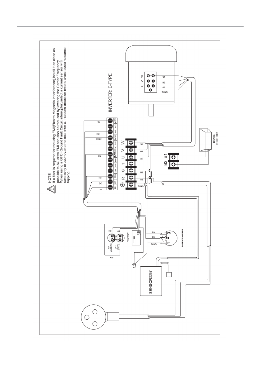
WIRING DIAGRAM
23
Page 24

Page 25

Page 26

The packaging is suitable for recycling.
Please dispose of it in a responsible manner.
EU Countries Only
Do not dispose of electric tools together with household waste material.
By law they must be collected and recycled separately.
Axminster Tools, Axminster Devon EX13 5PH
axminstertools.com
 Loading...