

Page 1
Watch
The Set Up
Guide
Here!
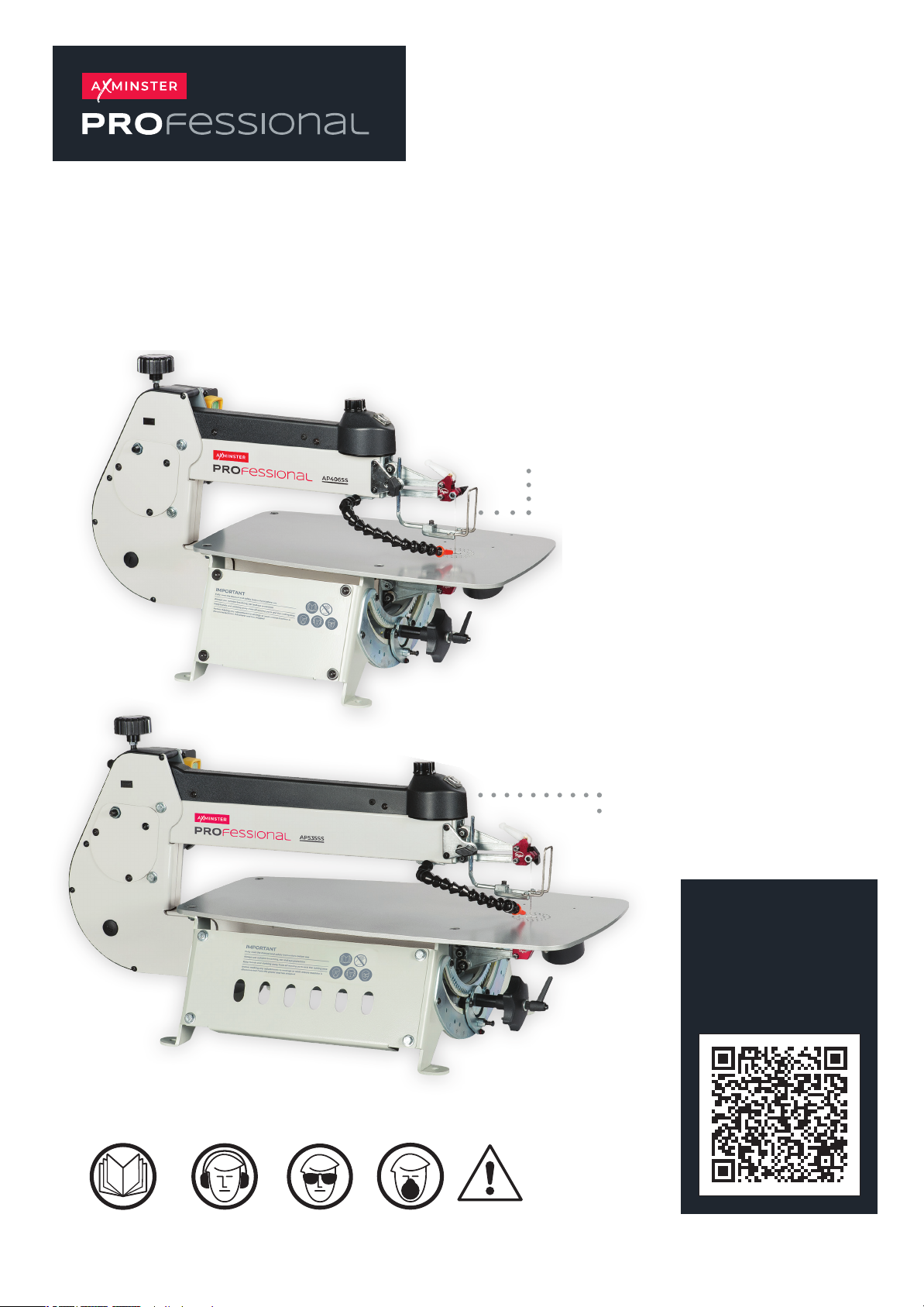
AP406SS, AP535SS
Scroll Saws
AP406SS Code 107653
AP535SS Code 107654
AP406SS
(KC-16)
AP535SS
(KC-21)
Original Instructions
AT:30/07/2025
BOOK VERSION: 9
The symbols below advise the correct safety procedures when using this machine.
Fully read manual
and safety instructions
b
efore use
Ear protection
should be worn
Eye protection
should be worn
Dust mask
should be worn
HAZARD
Page 2
INDEX OF CONTENTS
Rules For Safe Operation 03
Safety Instructions 04
Electrical Requirements 05
Identication of Main Parts & Components 06
Unpacking & Set Up 07
Installation & Assembly 07-08
Choosing & Installing a Saw Blade 08-09-10
Operating Instructions 11-12-13
Maintenance, Adjustments & Servicing 14-15
Changing the Fuse 15
Specications 15
Stand Assembly 16-17
Exploded Diagrams/Lists
KC-16, KC-21Exploded Diagram (A) 18-19
KC-16, KC-21Exploded Diagram (B) 20-21
KC-16, KC-21Exploded Diagram (C) 22-23
Base Mounting Holes 24
Wiring Diagram 25
2
Page 3

RULES FOR SAFE OPERATION
To help ensure safe operation, please take a moment to learn
the machine’s applications and limitations, as well as potential hazards.
Axminster Tools disclaims any real or implied warranty and holds itself harmless
for any injury that may result from the improper use of its equipment.
1. Be sure to read, understand and follow all safety warnings and
instructions in the supplied Operator’s Manual.
2. Do not operate the saw when tired, distracted, or under the
eects of drugs, alcohol or any medication that impairs reexes
or alertness. Stay alert! Give your work your undivided attention.
3. Keep the work area well lit, clean and free of debris. Cluttered
areas and benches invite injuries.
4. Keep children and shop visitors at a safe distance while
operating the saw; do not permit them to operate the scroll saw.
5. Childproof and tamper proof your shop and all machinery
with locks, master electrical switches and switch keys, to prevent
unauthorised or unsupervised use. Fine particulate dust is a
carcinogen that can be hazardous to health. Work in a well
ventilated area and use a dust collector whenever possible.
7. Wear approved safety glasses, dust mask and nonskid
footwear. Do not wear loose clothing, gloves, bracelets, necklaces
or jewellery while operating the saw. Keep long hair contained by
wearing protective hair covering.
8. Be sure all adjustment tools, wrenches or other
clutter are removed from the machine and/or the table surface
before operation. When not in use, tools should be locked-up
in a dry place, out of children’s reach and away from ammable
substances.
9. Keep hands well away from saw blade and all moving parts.
Use a brush, not hands, to clear away chips and sawdust.
12. Avoid working from awkward or o balance positions. Do not
overreach while cutting; keep both feet on oor. Never lean over
or reach behind the blade and never pull the work piece through
the cut from behind.
13. Never stand or lean on the saw. Serious injury could occur if the
unit is tipped over or if the blade is unintentionally contacted.
14. Use of parts and accessories NOT recommended by Axminster
Tool Centre may result in equipment malfunction or risk of injury.
15. Never leave the machine unattended while running or with
the power “ON”.
16. Always turn o and disconnect from power source before
servicing or changing accessories, blades, bits, and cutters, or
before performing any maintenance or adjustments.
17. Make sure that switch is in the “OFF” position before plugging
in the power cord. Do not use the saw if the power switch is
defected, have defective switches replaced by an authorized
service centre.
18. Make sure saw is properly grounded. If equipped with a three
prong plug it should be used with a three-pole receptacle. Never
remove the third prong. Avoid body contact with grounded
surfaces (e.g. pipes, radiators, stoves, refrigerators).
19. Repairs to the saw should only be carried out by qualied
people using original spare parts. A guard or other damaged part
should be properly repaired or replaced by an authorized service
centre.
10. Be sure that the saw blade is properly installed, and in the
correct cutting direction, before operation. Always use a clean,
properly sharpened blade. Dirty or dull blades are unsafe and can
lead to accidents. Also, be sure the blade has gained full operating
speed before beginning to cut.
11. Do not push or force wood into the blade. The saw will perform
better and more safely when working at the rate for which it was
designed. Do not use for purposes not intended.
3
20. Inspect power cords and extension wires periodically. If
damaged, have them repaired by an authorized service facility.
Never yank cords and wires and keep away from heat, oil, and
sharp edges.
21. This tool is for indoor use only. Do not expose to rain or use
in wet or damp locations.
Page 4
SAFETY INSTRUCTIONS
Additional Safety Instructions
Specific o the Scroll Saw
Because each shop situation Is unique, no list of safety guidelines can ever be complete.
The most Important safety feature In any shop Is the knowledge and good Judgement of the user. Use common sense and
always keep safety considerations, as they apply to your individual shop situation first and oremost In mind. If you have
any doubts about the safety of an operation you are about to perform: STOP! Do not perform the operation until you have
validated from qualified ndividuals If the operation Is safe to perform and what Is the safest method to perform It.
1. Material hold-down must be properly set and remain In
Position during use.
2. Never reach under the table when operating or make any
adjustments while the scroll saw Is run ning.
3. Secure the saw to the work bench with clamps or mounting
hardware.
4. Where possible, use clamps or a vice to secure your
workplace. It Is safer than using your hand.
5. Do not lift or carry the saw by the upper arm.
6. Make sure blade tension Is properly adjusted.
7. Avoid awkward hand positions where a sudden slip could
cause a hand to move Into the saw blade. Do not place ngers or hands in the path of the saw blade.
8. When removing short workplaces, or cleaning up around the
table, be sure that the switch Is In the OFF position and that
the blade has come to a complete stop.
9. Never turn the saw ON before making sure that the table Is
clear except for the workplace and related feed or support
devices for the operation planned.
10. Check for proper blade size and type.
11. Do not attempt to saw stock that does not have a at
surface unless a suitable support is used.
12. Turn o motor If the material resists being backed out of
an Incomplete cut. Use appropriate speed for applications.
13. CAUTION: Some wood contains preservatives such as
copper chromium arsenate (CCA) which can be toxic.
When cutting these materials, extra care should be taken
to avoid Inhalation and to mini mize skin contact.
14. Always use a dust mask and safety glasses when sawing.
15. Keep guards In place and In working order.
16. Make sure your ngers do not contact the terminals of the
power cord plug when plugging in or unplugging the saw.
17. Never overfeed or force work Into the blade.
18. Check for alignment and binding of all moving parts,
broken parts, mounting and any other con ditions that
may aect the saw’s operation.
19. Keep handles dry and free from oil and grease.
To avoid electrical shock, ensure machine Is properly grounded. Do not operate In
damp conditions. Disconnect from power supply before servicing. Replace fuse with
the same type and rating only - 3 Amp.
Be sure to read and understand owners manual before operating.
4
Page 5
ELECTRICAL REQUIREMENTS
Before connecting the machine to the power
source, verify that the voltage of your power
supply corresponds with the voltage specied on
the motor I.D. Nameplate. A power source with
greater voltage than needed can result In serious
injury to the user as well as damage to the machine.
If in doubt, contact a qualied electrician before
con necting to the power source.
This tool is for indoor use only. Do not expose to
rain or use In wet or damp locations.
GROUNDING INSTRUCTIONS EXTENSION CORDS
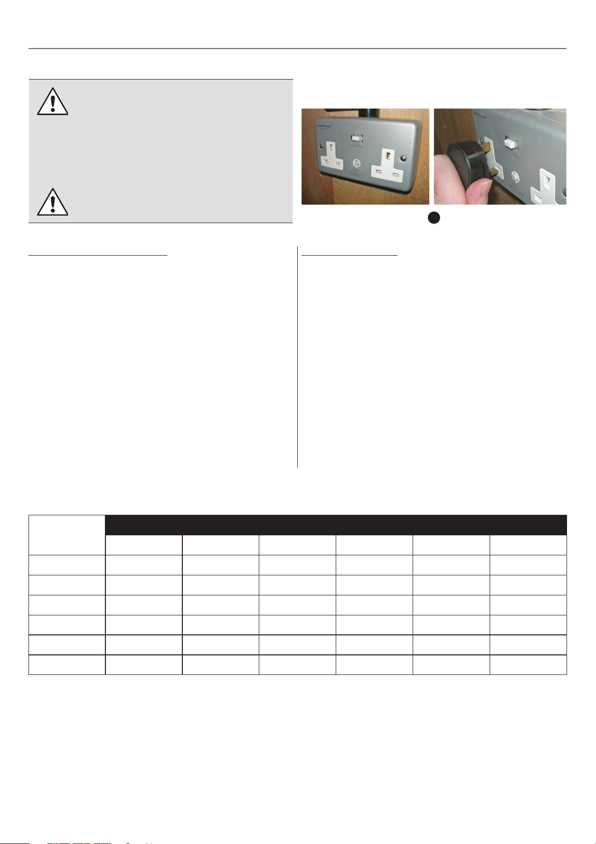
a
In the event of an electrical malfunction or short circuit,
grounding reduces the risk of electric shock. The motor of
this machine Is wired for 240V single phase operation and Is
equipped with a 3-conduc tor cord and a 3-prong grounded
plug to t a grounded type recep tacle, ( a )
Note: The use of an adaptor plug Is Illegal in some areas.
Check your local codes.
DO NOT MODIFY THE PLUG PROVIDED.
If It will not t your receptacle, have the proper receptacle
Installed by a qualied electrician.
CHECK with a qualied electrician or service person If you
do not completely understand these grounding Instruc tions,
or If you are not sure the tool is properly grounded.
AMPERES
(AMPS)
25 FEET 50 FEET 75 FEET 100 FEET 150 FEET 200 FEET
EXTENSION CORD LENGTH
USE ONLY 3-WIRE EXTENSION CORDS THAT HAVE 3-PRONG
GROUNDING PLUGS AND 3-POLE RECEPTACLES THAT
ACCEPT THE TOOLS’ PLUG. REPAIR OR REPLACE A
DAMAGED OR WORN POWER CORD OR PLUG IMMEDIATELY.
If you nd It necessary to use on extension cord with your
machine make sure the cord rating Is suitable for the amperage
listed on the motor I.D. plate. An under sized cord will cause a
drop in line voltage resulting In loss of power and overheating. The accompanying chart shows the correct size extension
cord to be used based on cord length and motor I.D. plate amp
rating. If In doubt, use the next heavier gauge. The smaller the
number the heav ier the gauge.
<5 16 16 16 14 12 12
5 TO 8 16 16 14 12 10 NR
8 TO 12 14 14 12 10 NR NR
12 TO 15 12 12 10 10 NR NR
15 TO 20 10 10 10 NR NR NR
21 TO 30 10 NR NR NR NR NR
* Based on limiting the line voltage drop to 5V at 150% of the rated amperes.
NR = Not Recommended
5
Page 6
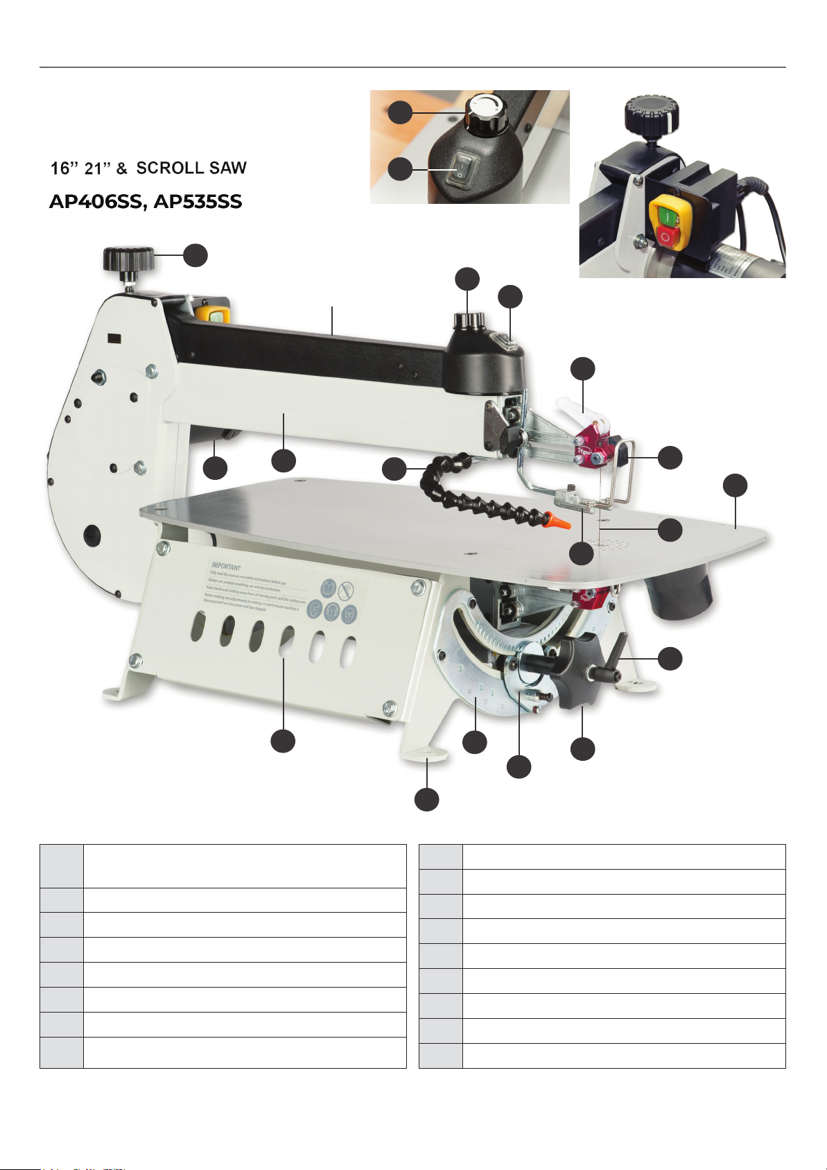
IDENTIFICATION OF MAIN PARTS & COMPONENTS
B
A
ON/OFF Switch (A)
Speed Control Dial (B)
C
A
AP535SS
B
NVR power isolating switch
Q
O
A VARIABLE BLADE SPEED
CONTROL KNOB
B ON/OFF SWITCH
C UPPER ARM TENSIONER
D BLADE CLAMP
E BLADE
F WORKPIECE HOLD DOWN
G TABLE
H BLADE TILT LOCKING LEVER
N
P
M
F
K
I
J
L
I TILT HANDLE
J ANGLE INDICATOR
K ANGLE ADJUSTMENT SCALE
L MOUNTING HOLES (4)
M BLOWER
N UPPER ARM
O MOTOR
P BLADE HOLDER SOCKETS
Q BLADE TENSION LEVER
D
G
E
H
6
Page 7
UNPACKING & SET UP
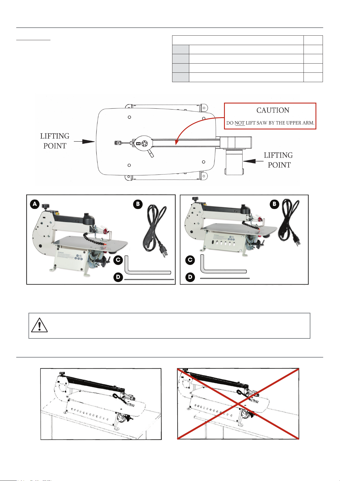
UNPACKING
Carefully unpack and remove the scroll saw and its
components from the box and check for missing or
damaged Items as per the list of contents below.
Note: Please report any damaged or missing
items to ‘Axminster Tools Customer Service’ on
(Call: 03332 406 406)
Once the parts have been removed from the packaging,
you should have the following Items:
AP406SS (KC-16) AP535SS (KC-21)
LIST OF CONTENTS Qty
A SCROLL SAW 1
B POWER CORD 1
C 3MM HEX KEY 1
D BLADE 1
Unscrew the 4 shipping bolts and remove the saw from the protective plywood shipping base. For your conven ience this scroll
saw Is shipped from the factory partially assembled and requires only minimal assembly and set up before being put into service.
Before starting the assembly, make sure that the switch Is In the “OFF” position and that the power
cord is unplugged. Do not plug In or turn on the scroll saw until you have completed the assembly
and Installation steps described In this section of the manual.
INSTALLATION & ASSEMBLY
The unit should be Installed on a at, sturdy and
stable surface able to support the weight of the
machine and the workpiece with ease.
Never install the machine over the edge of a table
or workbench.
7
Page 8
INSTALLATION & ASSEMBLY
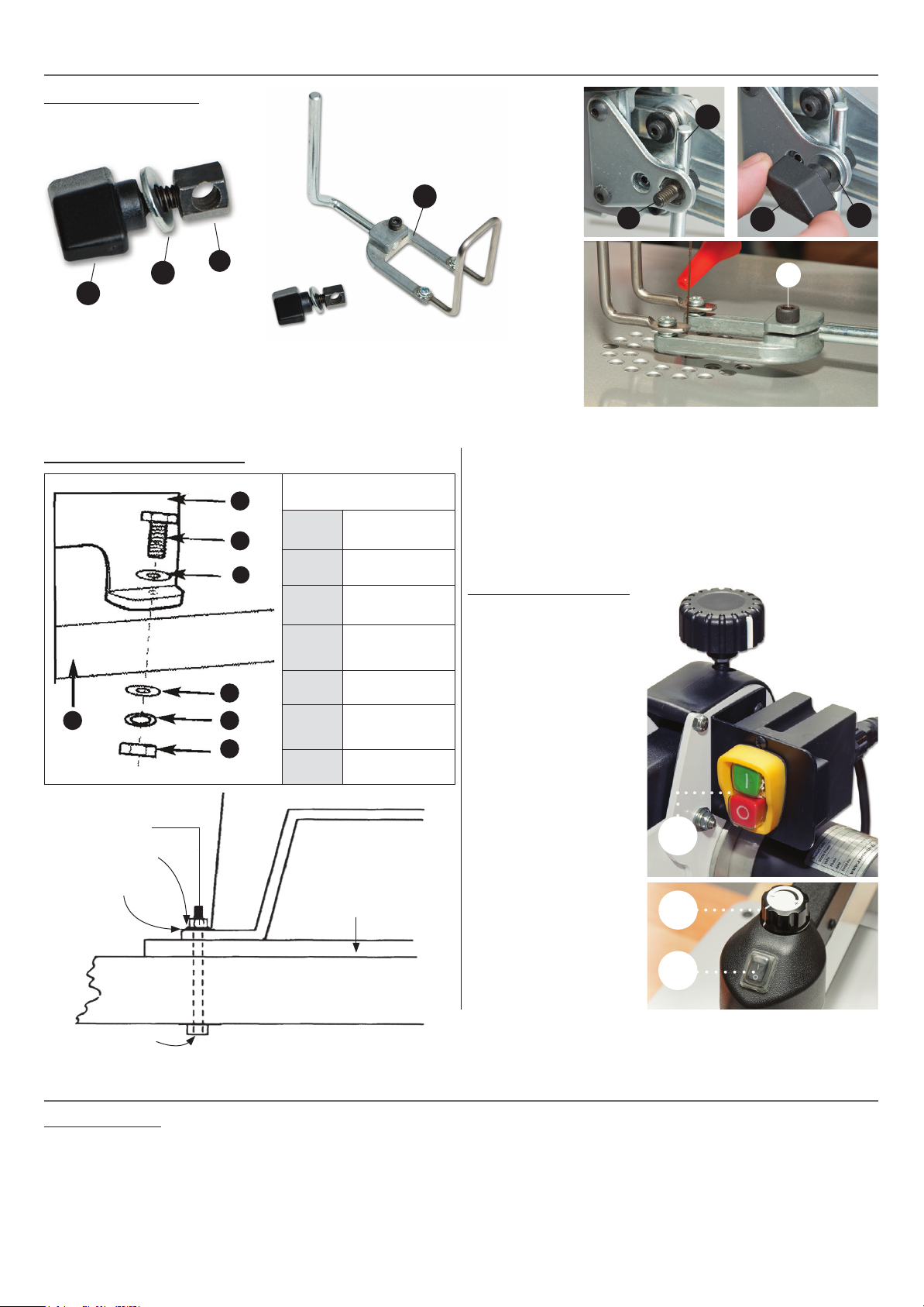
Saw guard assembly
d
d
c
a
b
b
c
a
Slot the guard clamping arm (d) through the pre-drilled hole in the hexagon clamp (c). Insert the hexagon
clamp (c) into the brackets hexagon recess, place the washer (b) over the hexagon clamp thread and secure
using the buttery clamping knob (a).
NOTE: DO NOT OVERTIGHTEN otherwise you may strip the thread
Mounting to Work Surface
e
d
f
g
HEX NUT
FLAT WASHER
LOCK WASHER
a
b
c
Asembly
a
b
c
d
e
f
g
1/2" FOAM PAD
OR CARPET
(OPTIONAL)
WORKBENCH
Saw
Hex Bolt
Flat Washer
Workbench
or Stand
Flat Washer
Locking
Washer
Hex Nut
It is strongly recommended that you mount the machine to a workbench or to
a purpose built stand, a pad between the scroll saw and the workbench/stand
is also recommended to reduce vibration.
Drill four 8mm holes in your workbench/stand and secure using
nuts bolts washers (Not Included).
NVR Switch assembly
A power NVR switch has
been attached to isolate the
scroll saw while not in use,
see g A.
• Press the ‘GREEN’ button
to put power to the scroll
saw then press the ‘ON’
button (B) to start the saw.
• Once operation has
be completed, press
the ‘RED’ button to isolate
the scroll saws power.
NOTE: MAKE SURE THE
SPEED CONTROL DIAL (C)
IS SET TO LOW BEFORE
YOU START UP THE SAW!
d
Saw guard assembly (d) assembled
A
C
B
HEX HEAD BOLT
CHOOSING & INSTALLING A SAW BLADE
Blade Selection
Blade selection Is dependent on the type and thickness of the material being cut, but Is also a matter of experience and personal
preference. There are numerous types of blades available on the market specically suited for vari ous cutting applications such as
metal-cung and spiral blades which cut In all directions. Try test-cutting with a sample of each to determine which blade works
best for you with dierent materials. Replacement blades can be purchased from a variety of sources. Ask your local tool or scroll
saw dealer for suggestions for unpinned 5” scroll saw blades based on what is available In your area.
8
Page 9
CHOOSING & INSTALLING A SAW BLADE
Some general guidelines to consider when choosing blades:
• Wide, thick blades with coarse teeth are suited to cutting straight lines and sweeping curves, but will not turn tight corners.
They will cut aggressively and leave a fairly smooth nish, but may leave burn marks If the work piece is turned too tightly.
• Narrower, thinner blades with ner teeth will cut more slowly, but will turn much tighter corners for cutting very
intricate work. They will Impart a very smooth, burnished nish that requires no sanding.
• Consider material thickness when selecting blades. Ensure that a minimum of two or three teeth are In con tact with the
workplace at all times. For example, when cutting 1 /8” thick material, use a blade with a mini mum of 16-20 teeth per Inch.
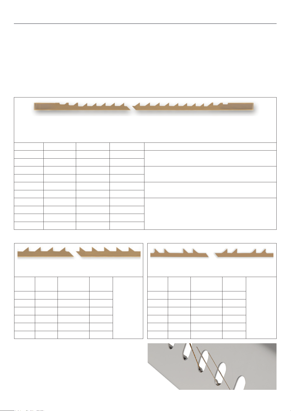
SKIP TOOTH
Regular evenly spaced tooth pattern. Considered the most common of scroll saw blades, they
are available In the widest range of sizes and provide a good combination of fast cutting action
with good chip clearance and a relatively smooth nish.
BLADE WIDTH THICKNESS TEETH/INCH
#2/0 .022 .010 28 or extremely Intricate sawing. Very tight cuts In 1/16”-
#0 .024 .011 25
#2 .029 .012 20 For tight radius work with thin materials, 3/32” -
#4 .035 .015 15
#5 .038 .016 12.5 For close radius work In materials 1 /8” or thicker. Good
#6 .041 .016 12.5
#7 .045 .017 11.5
#9 .053 .018 11.5
#11 .059 .019 9.5
#12 .062 .024 9.5
1 / 4” wood veneer, plastic, hard rubber, pearl, etc.
1/2” wood veneer, wood, bone, bre, plastic, etc.
,or sowing hard and soft woods, bone, horn, plastic, etc.
Popular sizes for cutting hard and soft woods, 3/16” up to
2” Also cuts plastic, paper, felt, bone, etc.
REVERSE TOOTH DOUBLE TOOTH
Reverse teeth at the bottom of the blades prevent
splintering to the underside of the workpiece.
BLADE WIDTH THICKNESS TEETH/
INCH
#2/OR .026 .011 28/20
#2R .029 .012 20/13
#5R .038 .016 12.5/9
#7R .049 .018 11.5/8
#9R .054 .019 11.5/8
#12R .062 .062 9.5/6
There are 12 sockets (mounting holes) on either side
of the base of the saw to hold blade storage “test tubes”
(tubes not supplied). Most blade retail ers sell blades
either already in the tubes or will be able to sell spare tubes
separately. Storing your spare blades in tubes, by size, right
on the base of the machine con be a great way to organize
your spore blades so that they are handy and available when
needed.
Some
as Skip
Tooth
blades.
Fast, clean cutting and very ecient chip clearance.
BLADE WIDTH THICKNESS TEETH/
INCH
#1D .026 .013 30
#3D .032 .014 23
#5D .038 .016 16
#7D .044 .018 13
#9D .053 .018 11
#12D .061 .022 10
9
Some
as Skip
Tooth
blades.
Page 10
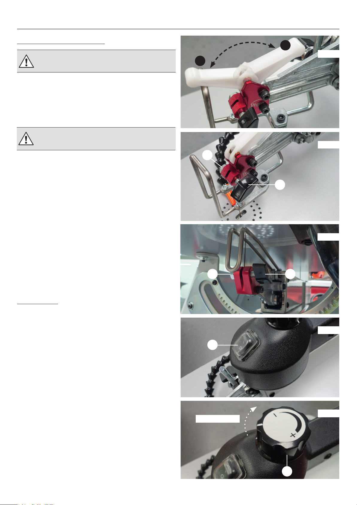
CHOOSING & INSTALLING A SAW BLADE
Installing or Changing Blades
Always turn o and unplug the machine
before removing, handling or changing blades.
1. Remove an Installed, worn or broken blade by ipping the
blade ten sion lever forward (position ( 1 ), then loosening the
thumbscrews ( a ) and ( b ), on the upper and lower blade
mounts ( c ) and ( d ) ( See Fig. 1 to 3 ).
2. Raise the upper arm and remove the blade.
NOTE: If the upper arm is xed in position,
turn to page 15 to adjust the arm tension!
3. With the blade teeth facing forward, slip one end of the
blade through the hole In the table and t each end of the
blade Into the corresponding upper and lower blade mounts,
then tighten the thumbscrews rmly by hand only - do not use
tools. Note: Over tightening the blade clamp tumb screws can
cause premature wear to the blades gripping surface and result
in blade slippage.
2
Fig.1
1
Fig.2
b
a
4. Push the blade tension lever back (position ( 2 ) to apply
tension on the blade.
Helpful Hints on blade tension: Determining correct
blade tension Is somewhat subjective. It is learned through
experience and is somewhat dependant on personal
preference. A properly tensioned blade will last longer and
be much less likely to break prematurely. If the blade tension
Is too loose, you will notice that the blade will have a tendency
to drift or slip o-line when cutting and you may also
experience excessive vibration or unusual noise. A blade
that is too tight will break prematurely.
On/Off Switch
A simple, dust protected rocker style on/o switch ( a ) is
located on the top of the saw. (See Fig. 4)
Adjusting the blade speed
The Scroll Saw Is equipped with a variable blade speed control
which allows you to select or ne-tune to the exact blade speed
required (from 400-1550 strokes per minute) for best results
based on the type and thick ness of material and type of blade
being used.
The blade speed control knob ( b ) , Is located on the top of
the machine. (See Fig. 5)
d
a
Fig.3
c
Fig.4
• To increase blade speed, turn the control knob clockwise.
• To decrease blade speed turn the control knob counter
clockwise.
Assuming the blade has been properly Installed In the blade
mounts, when the blade tension lever Is pushed fully back
towards the rear of the saw. The blade should be properly
tensioned. Test the blade tension by lightly pulling on the
blade, like you would a guitar string, with your nger. If the
blade is tight and tensioned correctly you will get a clear and
even note. If. so, you are ready to proceed to operating and
cutting with the saw.
Increase speed
Fig.5
b
10
Page 11
OPERATING INSTRUCTIONS
Blade speed selection Is subjective and Is dependant on a
variety of factors: type and thickness of material being cut, type
of blade being used, feed rate, required nish quality as well as
experience, personal preference and com fort level of the user.
There are no hard and fast rules. Be patient - practice and experience will be your best teacher. Here are some general guidelines to consider when selecting/adjusting blade speed:
• For best results and smoothest most ecient cutting, always
select the highest blade speed that you are comfort able using
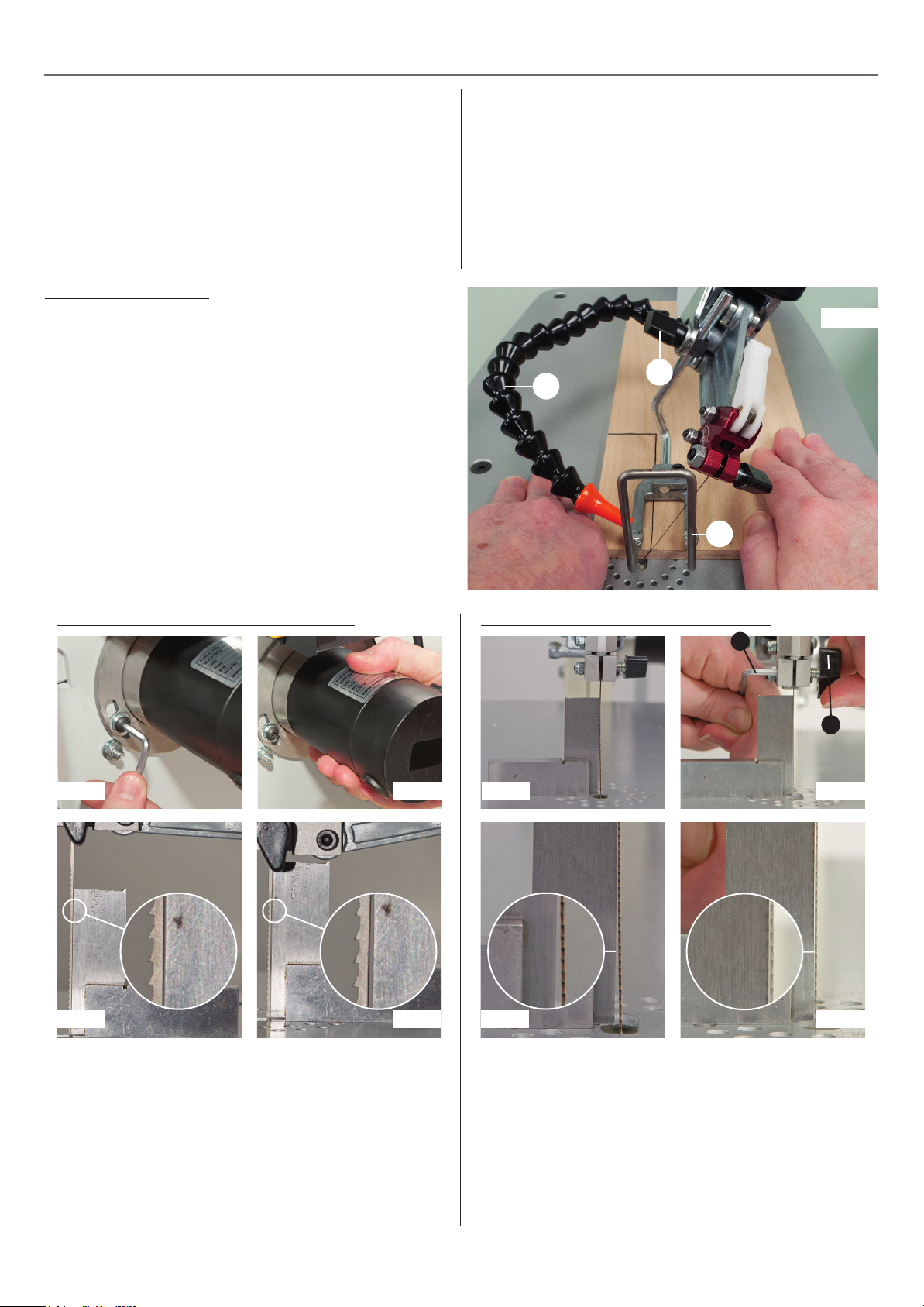
Adjusting the Blower
The KC-16 KC-21 is equipped with a built-in blower to help
clear cutting dust from the workpiece surface In front of the
blade and on any reference lines. Adjust the blower tube ( a )
as needed to point the nozzle at the blade to set It at a
comfortable distance so as not to obstruct your hand
movement as you work. (See Fig. 6)
Workpiece Hold-Down
The workplace hold down ( b ) (See Fig. 6) can be adjusted to
assist In preventing the blade from lifting the workpiece up
from the table during the cut. Loosen the thumbscrew ( c )
to set the height to your convenience based on the thickness
of the workplace. Before cutting, test to make sure that the
hold-down Is not adjust ed too tightly to the workplace or
that It obstructs the movement of the workpiece.
based on your experience and skill level.
• Generally speaking, harder or denser workpiece material
requires slower blade speeds.
• Slower speeds also work better when very thin blades, or
when cutting most metals as well as for brittle or delicate
material such as ne veneers.
• Some wood species will have a tendency to burn quicker at
higher blade speeds. To avoid additional sanding later, reduce
blade speed and feed speed at the rst signs of burn marks on
the workpiece.
Fig.6
c
a
b
Adjusting the Osolation (Front to Back)
Fig A Fig B
Fig C Fig D
Place a 90˚ square up against the blade, the blade movement
can be set between course and ne for dierent cutting tasks,
this can be adjusted by rotating the motor within its’ mounts.
Loosen the motor mounting cap head bolts, see gs A enough
to be able to rotate the motor (this can be quite sti to turn),
start the machine and run at approximately 1/4 speed. By
rotating the motor, see g B and carefully observing the blade
you will be able to see the blade changing its setting. The
nest setting is where the blade moves vertically with the
least amount of movement, see g C backward and forwards
Top & Bottom Blade holder Alignment
a
b
Fig A Fig B
Fig C
horizontally. This should also be where the machine vibrates the
least. When you have the setting where you wish it to be, tighten
the motor mounting bolts.
If the blade is out of alignment please follow the procedures
below for adjusting the top and bottom blade holders:
Place a 90˚ square up against the blade, see g A. U sing a 4mm
Hex key (a) adjust the grub screw and buttery nut (b), see g B,
until the blade is parallel with the square. (See gs C and D).
Fig D
11
Page 12
OPERATING INSTRUCTIONS
Basic 90° Straight or Curved Cuts
All cuts made with the blade at 90° to the table follow the some
basic principals. Start by marking or transferring your pattern or
reference lines onto you workplace.
Note: The KC-16 has a 16” throat that allow tor a workpiece
of up to 16” of clearance to swing completely around with
out hitting the bock of the saw It necessary, rough-cut the
workpiece down to a workable size before starting
intricate work on the scroll saw. The above note applies
also to the KC-21 (21”) scroll saw.
1. With the saw turned o and unplugged, install the
appropriate blade for the type of material to be cut and
the type of cut to be made (Refer to the section “Choosing
and in stalling a Saw Blade” on page 9).
2. Adjust the workplace hold-down and the blower nozzle
to your liking.
3. Turn on the sow and set the speed controller to the
desired blade speed.
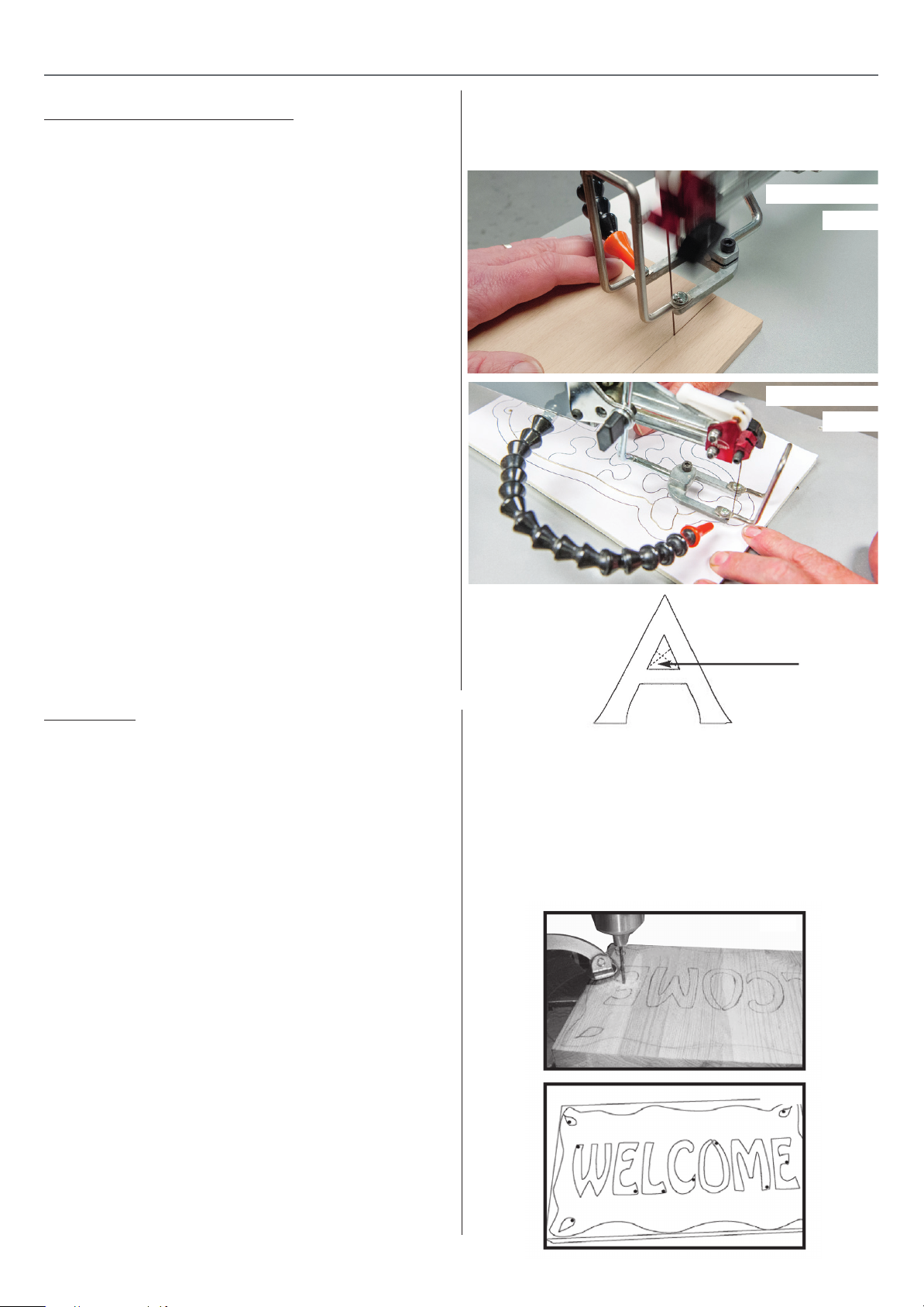
4. With your ngers holding the piece rm to the table,
and using your thumbs for directional control, (See Fig 7
& 8) feed the workplace Into the blade using steady, even
pressure.
5. Make sure that the blade Is cutting on the waste side of
your reference line and adjust feed direction sllghty as
needed to compensate for blade drift.
Cutting Tips: To stay In control on tight curve cuts, slow
down your feed rate as needed to allow the blade teeth
time to make the cut. Avoid coming to a complete stop
whenever possible as this can leave burn marks on the
workpiece and also makes It more difficult o get the piece
re-started and moving through the cut again. Avoid forcing
through a curve cut as this can cause the blade to twist and
cut o-track or may even cause the blade to break.
Straight Cuts
Fig.7
Curved Cuts
Fig.8
Fig.9
Remove portion
Fret Cutting
Fret or Inside cutting Is an operation that can only be performed on a scroll saw. Fret cutting Involves drilling a small
guide or pilot hole through the Interior of your pattern on the
workplace, then disconnecting one end of the blade which Is
tted through the guide hole and re-connected; essentially
using this guide hole as the starting point to cut out the piece
from within. A typical example of fret cutting would be removing the canter portion of lettering. (See Fig.9)
The KC-16, KC-21 ls a great tool for fret cutting because, unlike
most scroll saws It allows you to raise the upper arm with the
blade attached, line up the guide hole In your workplace with
the hole In the table and then lower the arm white guiding the
blade through the hole from above (see step by step
Instructions below). This can be a very useful time saving feature, particularly for Intricate or complex fret designs that can
Involve dozens or even hundreds of holes.
Note: The upper arm locks in place in the raised position
for easier insertion of the blade through the hole in the
workpiece and for easier blade change.
1. With the saw turned o and unplugged, Install the
appropriate blade for the type of material to be cut and
the type of cut to be mode (Refer to the section “Choosing
and Installing a Saw Blade” on page 9 of this manual).
2. With your pattern or design transferred onto the
workplace, drill a guide hole In the Inside waste portion of
the workpiece. (See Fig. 10) Make sure that the hole Is large
enough for the blade to t through.
Helpful hints on drilling guide holes: It multiple fret cuts are
required on the same workpiece, drill all of your required
guide holes before taking the workpiece to the scroll saw.
This will keep you from going back and forth from the saw
to the drill press.
To prolong blade life by limiting unnecessary cutting, drill your
guide holes as close as possible to your reference lines.
(See Fig. 11)
Fig.10
Fig.11
12
Page 13
OPERATING INSTRUCTIONS
3. Release tension on the blade by ipping the blade tension lever forward.
4. Loosen the thumbscrew on the lower blade mount, located under the table, to release the blade from the mount.
5. Raise the upper arm assembly which will lift the blade up through the hole and above the table.
6. Position the workpiece on the table so that the guide hole lines up with the hole In the table.
7. Lower the arm assembly with one hand while guiding the blade through the hole In the workpiece and table.
8. Re-Install the bottom end of the blade In the lower blade mount and tighten the thumbscrew to secure the
blade In the lower blade mount.
9. Flip back blade tension lever to re-tension the blade and test the blade tension as described In “Installing or
Changing Blades· section of this manual.
10. To begin cutting follow the same steps as described In “Basic 90° straight or curved cuts• section on
page 12 of this manual.
To reduce the risk of Injury, always turn off the s w and wait for the blade to come to a complete stop
before reaching in to remove waste material from a fret cut.
Angle or Bevel Cutting
One of the unique features of the KC-18 KC-21 Scroll Saw Is
the ability to tilt the head of the saw In order to make angle or
bevel cuts. The table and the workpiece always stay horizontal
(parallel to the oor) while the blade tilts, keeping your hands in
the same comfortable cutting position as they would normally
be for regular right angle cuts. Because you are not ghting
gravity or working with your hands or wrists bent In awkward
positions, It con be a huge advantage and makes It easier and
safer to make accurate bevel cuts.
a
b
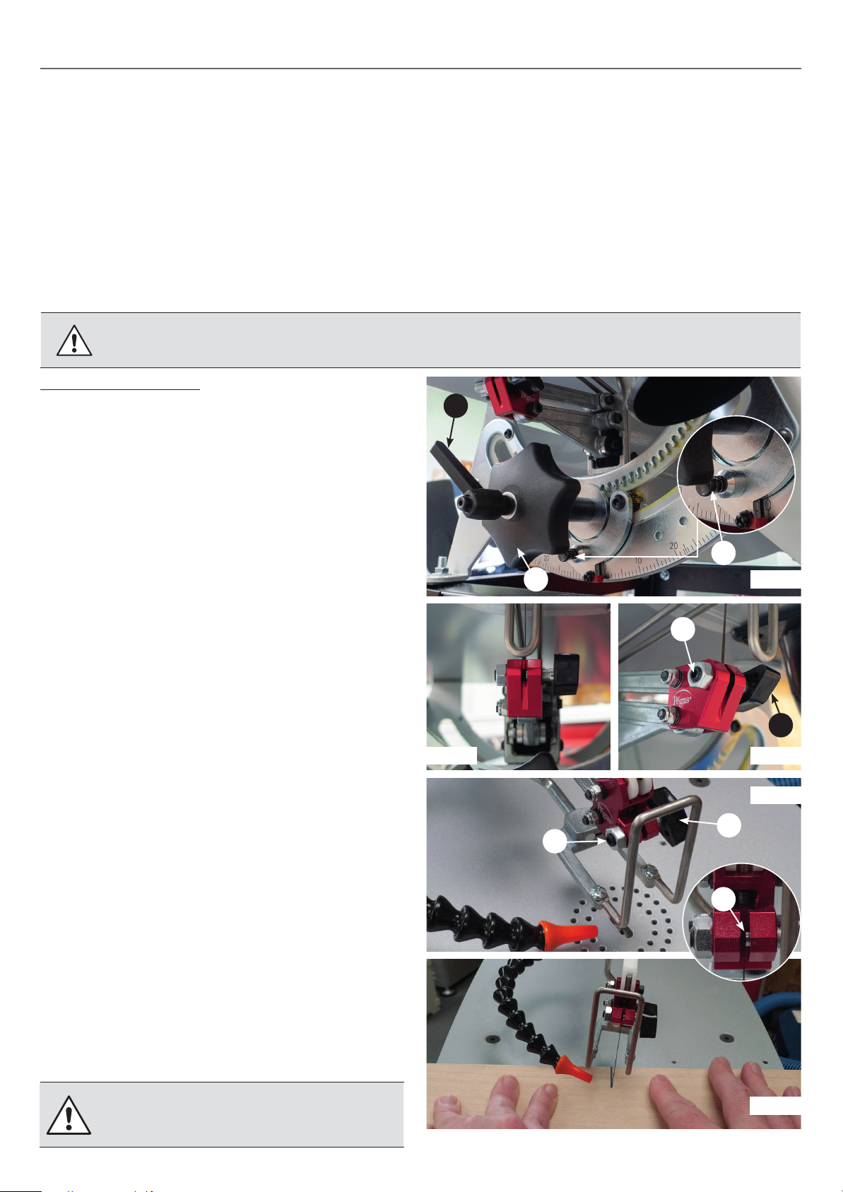
The blade tilt controls ore located under the table at the front
saw. (See Fig. 12)
c
Fig.12
To tilt the blade for bevel cutting:
1. Release the locking lever ( a ) by turning counter-clockwise.
2. Turn the tilting handle ( c ) left or right to set the blade to
the desired angle.
Note: Push in and hold the spring loaded indexing pin ( b )
to locate the following common angles: 90˚, 45˚, 30˚ &
22.5˚ both left and right.
When tilting the blade to the left at extreme angles, it may
be necessary to remove and reverse the lower blade mount
thumbscrew ( c ) assembly in order to maximise clearance
under the table. (Fig. 13 shows the lower blade mount in
default position.
To avoid kinking or damaging the blade in the holder, when
making adjustments make sure the set screw ( d ) (opposite
the thumbscrew ( e ) is threaded in to the holder to protrude beyond the blade slot ( f ). (See Fig. 14 &15)
3. Tighten the locking lever ( a ) to secure the blade at the
desired angle.
4. To begin cutting follow the same steps as described In
“Basic 90° straight or curved cuts” section on page 11 of
this manual. Fig. 16 shows the scroll saw In position for
bevel cutting.
d
e
Fig.13 Fig.14
Fig.15
e
d
f
To reduce the risk of injury, always turn o the saw
and wait for the blade yo come to a complete stop
before reaching in to remove waste material.
Fig.16
13
Page 14
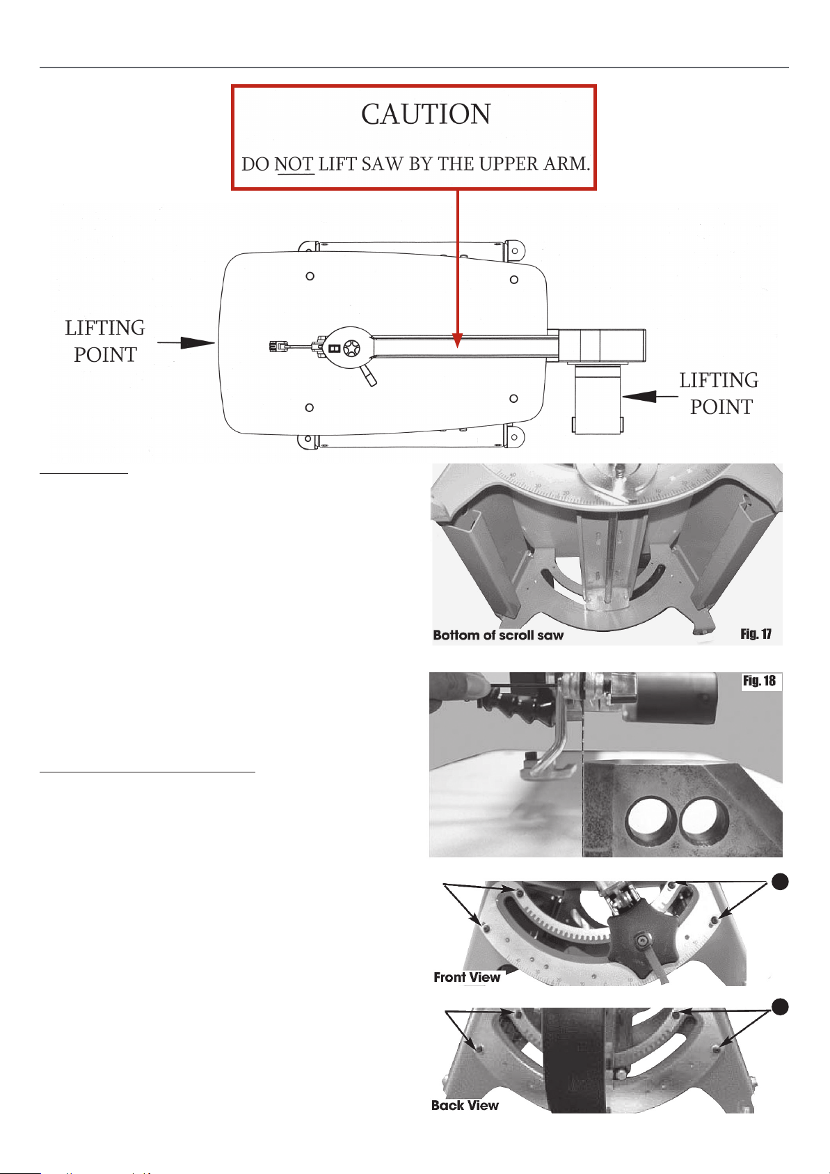
MAINTENANCE, ADJUSTMENTS & SERVICING
Maintenance
Always release tension on the blade when the saw Is not
In use.
• Clean the saw regularly with a soft bristle brush or by
vacuuming to keep cutting dust from accumulating.
• An occasional application of a light dab of grease on the front
and rear trunnions (See Fig. 17) will keep the tilting mechanism working smoothly. If you nd the tilting mechanism
becoming more dicult to operate, thoroughly wipe o any
built-up cutting dust on the trunnions and re-apply a little
grease.
• The bearings in the drive mechanism are sealed and perma-
nently lubricated and do not need to be oiled or greased.
Squaring the Blade to the Table
Depending on frequency of use and how much the tilting
mechanism is used, normal wear will over time cause the blade
to come slightly out of alignment with the table.
Periodically check the blade is square with the table. When
needed, adjust as described in the following steps to re align
the blade square to the table.
1. Turn o and unplug the saw.
2. Using the blade tilt controls at the front of the saw, set the
blade angle to read O - which Is 90° vertical to the table.
3. Set a machinists square on the table and against the blade
to verify the blade angle. (See Fig. 18)
4. If the blade angle requires adjustment loosen the 4 bolts
In the front trunnion ( a ) well as the 4 bolts on the rear
trunnions ( b ).
5. By hand, move the entire head to bring the blade square to
the table.
6. With the blade square to the table hold the head in
posi tion and re-tighten the bolts on the front and rear
trunnions.
a
b
14
Page 15
MAINTENANCE, ADJUSTMENTS & SERVICING
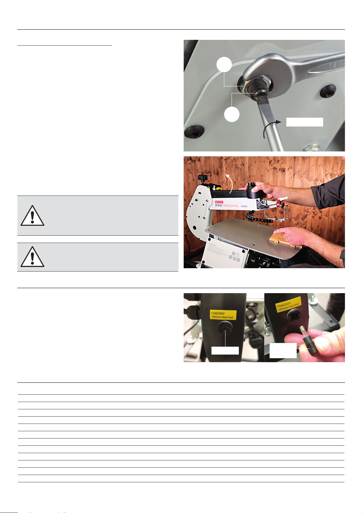
Upper Arm Tension Adjustment
Over time with normal wear the upper arm adjustment
screw (A) may require slight adjustment in order to hold
the arm in the raised position when the arm is lifted by the
operator.
To rest the adjustment screw:
1. Remove the blade and with the upper arm down set the
arm more or less parallel to the saw table.
2. Loosen the locking nut (B) with a 14mm spanner.
3. Turn the adjuster screw clockwise, 1/4 of a turn at a time
until there is enough resistance to hold the arm in the
raised position.
4. Re-tighten the lock nut (B) and check again to make sure
the upper arm will now stay up when lifted. If not repeat
these steps again, using 1/4 turn adjustments.
NOTE: DO NOT overtighten the adjustment
screw! Over tightening the screw will apply to
much tension and prevent the free movement
of the arm during operations causing damage
to your scroll saw over time.
B
A
1/4 of a turn
NOTE:
if the arm is fi ed in position with no
movement turn the screw anti-clockwise,
1/4 of a turn at a time and check again.
CHANGING THE FUSE
The scroll saws takes a 5 Amp 20 x 5mm glass fuse,
follow the instructions below on how to change the fuse.
1. Unplug the scroll saw from the mains.
2. Unscrew the fuse cap to the rear of the scroll saw and
remove the 5 AMP fuse.
3. Insert a new 5 AMP fuse into the end cap holder.
4. Re-insert the fuse assembly and lightly tighten.
Fuse
End cap
holder
SPECIFICATIONS
Code 107653 107654
Model AP406SS (KC-16) AP535SS (KC-21)
Rating Trade/Professional Trade/Professional
Power 230V 50Hz 320W 230V 50Hz 320W
Throat 406 mm 535 mm
Stroke 18 mm 18 mm
Cuts per Minute 400 -1,400 400 -1,550
Max Depth of Cut 51 mm 51 mm
Noise Level dB (A) 67dB(A) 67dB(A)
Table Size 305 x 470 mm 345 x 597 mm
Arm Tilt Left 35° Right -45° Left 35° Right -45°
Overall L x W x H 686 x 380 x 432 mm 812 x 380 x 387 mm
Weight 24.5 kg 29.5 kg
15
Page 16
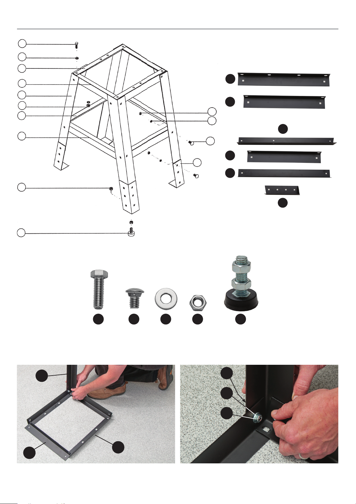
STAND ASSEMBLY
A
B
1
2
3
C
4
C
B
1
2
3
5
E
4
6
5
D
6
D
A E
x4 M8
Bolts
x24 M8
Coach Bolts
3
B C D
x32 M8
Washers
x28 M8
Nuts
x4 Thread Rubber
Foot
E
B
C
1
2
Step 2Step 1
16
Page 17
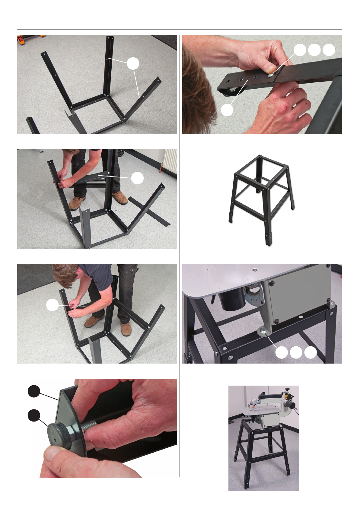
STAND ASSEMBLY
E B C
3
6
Step 7Step 3
Use the holes in the bracket (6) to adjust the stand height
4
6
D
Step 4
Stand assembled
5
A B C
Step 5
Lower the scroll saw on top of the stand and lineup the holes,
secure using the four bolts (A) washers (B) and Nuts (C)
Step 6
17
Page 18
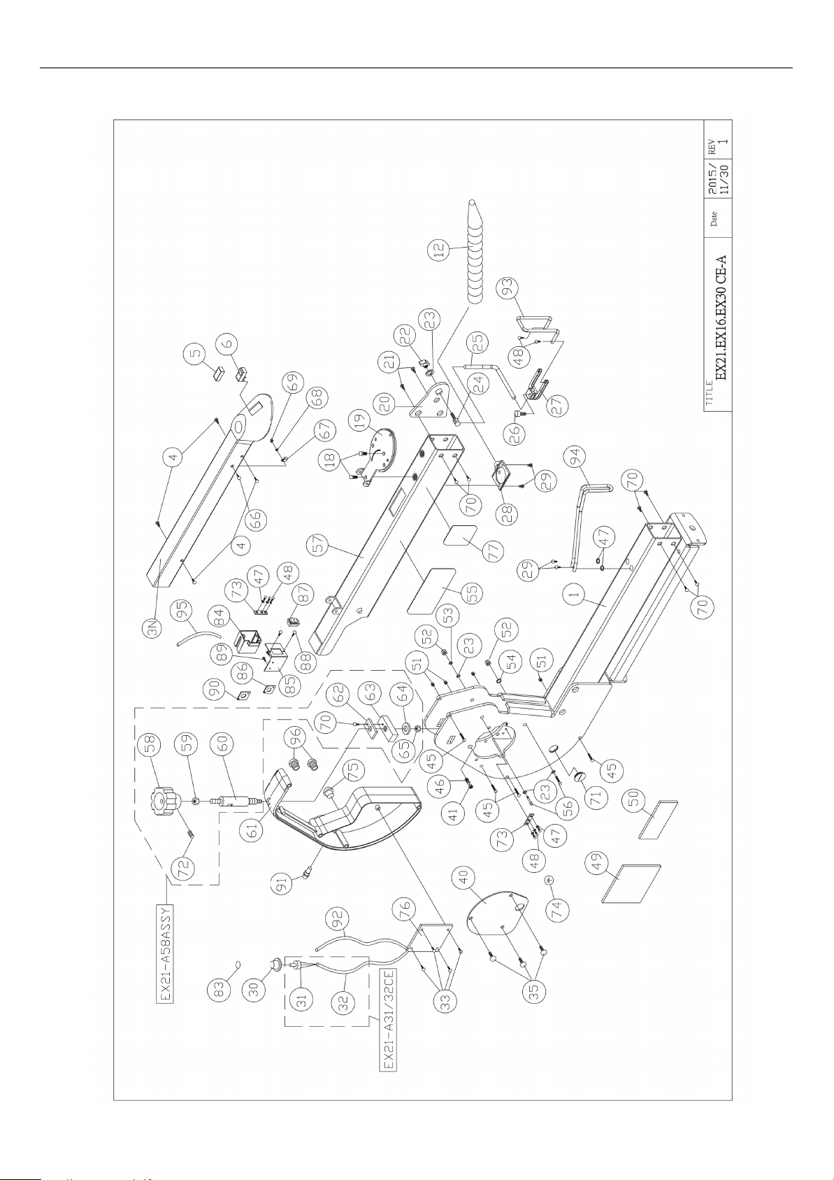
EXPLODED DIAGRAMS/LISTS
KC-16 - KC-21 - Diagram A
(KC-16) (KC-21)
18
Page 19

KC-16 - KC-21 - Diagram A
EXPLODED DIAGRAMS/LISTS
REF. PART NO. DESCRIPTION SPECIFICATION QTY
01 EX21-A01 Main Body
EX16-A78 Main Body
EX30-A01 Main Body
03N EX21-A03N Top Cover
EX16-A79 Top Cover
EX30-A03 Top Cover
04 EX21-A04 Allen Screw #10-32x1/4
05 EX21-A05 Switch Cover
06 EX21-A06 Switch
12 EX21-A12 Air Nozzle
18 EX21-A18 BOLT 1/4-20x1/2
19 EX21-A19 Upper & Lower
20 EX21-A20 Hold Down Mount
21 EX21-A21 Allen Screw #10-32x3/8
22 EX21-A22 Hold Down Clamp
23 EX21-A23 Washer 1/4x16x1.8
24 EX21-A24 Hold Down Clamp
25 EX21-A25 Hold Down Bar
26 EX21-A26 Cap Screw #10-32x1/2
27 EX21-A27 Hold Down Forks
28 EX21-A28 Dust Blower
29 EX21-A29 Tap Screw #8-32UNF3/8” 4
30 EX21-A30 VR Knob
31 EX21-A31CE VR
32 EX21-A32CE Control Cable
EX16-A81 Control Cable
EX30-A32CE Control Cable
EX21A31/32CE
33 EX21-A33 Screw M4x8 4
35 EX21-A35 Allen Screw 1/4-20x1/2 3
40 EX21-A40 Gear Cover 1
41 EX21-A41 Nut 3/8xT5. 5 1
45 EX21-A45 Allen Screw #10-32x2-1/4 4
46 EX21-A46 Screw 3/8x5/8 1
47 EX21-A47 Washer #8 8
48 EX21-A48 Screw #8-32x1/4 8
49 EX21-A49 Motor Label 1
50 EX21-A50 Warning Label 1
51 EX21-A51 Nylon Nut #10-32 4
52 EX21-A52 Nylon Nut 1/4-20UNC 2
53 EX21-A53 Lock Washer 1/4. 1
54 EX21-A54 Flat Washer 1/4. (0. D. 13) 1
Tension Plate
Plate
Knob
Screw
VR-With control
cable
55 EX21-A55 Label 2
56 EX21-A56 Screw 1/4*2-1/2 2
57 EX21-A57 Upper Arm
EX16-A80 Upper Arm
EX30-A57 Upper Arm
58 EX21-A58 Knob
EX21-A58ASSY Upper arm rising
59 EX21-A59 Nut M8
60 EX21-A60 Adjusting lever
61 EX21-A61 Control Box
62 EX21-A62 Cross Block
63 EX21-A63 Housing Cross
64 EX21-A64 Flat Washer M6x16x2
65 EX21-A65 Nylon Nut M6
66 EX21-A66 Allen Screw #10-32x1/2
67 EX21-A67 R Fastener ACC2
68 EX21-A68 Washer #10
69 EX21-A69 Nylon Nut #10-32
70 EX21-A70 Allen Screw #10-32x5/16
71 EX21-A71 Button
72 EX21-A72 Set Screw M4x5
73 EX21-A73 Ground Plate
74 EX21-A74 Ground Label
75 EX21-A75 Strain Relief PG11
76 EX21-A76 Motor Control Set
EX16-A82 Motor Control Set
EX30-A76 Motor Control Set
77 EX21-A77 Label
83 EX21-A83 Label
84 EX21-A84 Switch Box
85 EX21-A85 Control plate
86 EX21-A86 Fixing plate
87 EX21-A87 Switch
88 EX21-A88 Round Head
89 EX21-A89 Round Head
90 EX21-A90 Fixing plate
91 EX21-A91 Fuse Holder
92 EX21-A92 Power Cord
93 EX21-A93 Protection brack-
94 EX21-A94 Protection brack-
95 EX21-A95 Short power cord
96 EX21-A96 Strain relief PG9 2
knob assembly
Retainer
Block
#10-24UNCx3/4”
Screw
#10-24UNCx5/8”
Screw
et-Up
et-Down
19
Page 20

EXPLODED DIAGRAMS/LISTS
KC-16 - KC-21 - Diagram B
(KC-16) (KC-21)
20
Page 21

KC-16 - KC-21 - Diagram B
EXPLODED DIAGRAMS/LISTS
REF. PART NO. DESCRIPTION SPECIFICATION Q’TY
01 KC21-B01 Trunnion 2
02 KC21-B02 Side Panel 2
KC16-B41 Side Panel 2
KC30-B02 Side Panel 2
03 KC21-B03 Rear Trunnion Plate 1
04 KC21-B04 Front Trunnion Plate 1
05N KC21-B05N Table 1
KC16-B42 Table 1
KC30-B05N Table 1
07 KC21-B07 Power Cord 1
08 KC21-B08 Spong Block 1
09 KC21-B09 Polyfoam 1
10 KC21-B10 Screw 1/4”-20UNC* 1/2” 1
11 KC21-B11 Lock Washer 1/4” 3
12 KC21-B12 Washer 1/4” 9
KC16-B43 Washer 1/4” Black 8
13 KC21-B13 Blade Tilt Washer 2
14 KC21-B14 Blade Tilt Drive Gear 2
15 KC21-B15 Screw 1/4-20UNC*3/4” 10
KC16-B44 Allen Screw 1/4-20UNC*3/4” 8
16 KC21-B16 Angle Follower 2
17 KC21-B17 Screw #10-32x5/16” 8
18 KC21-B18 Washer #10x12x1 8
19 KC21-B19 Nut 1/4”-20UNC 12
20 KC21-B20 Angle Indicator 1
21 KC21-B21 Allen Screw 1/4”-20x1” 2
22 KC21-B22 E Ring ETW-3 1
23 KC21-B23 Tilt Detent Barrel 1
24 KC21-B24 Spring 1
25 KC21-B25 Detent Plunger 1
26 KC21-B26 Tilt Handle 1
27 KC21-B27 Washer 1/4”x16X3 1
28 KC21-B28 Blade Tilt Locking
29 KC21-B29 Flat Head Screw 1/4”-20x3/4 4
36 KC21-B36 Tilt Lock Draw Rod 1
KC16-B45 Tilt Lock Draw Rod 1
KC30-B36 Tilt Lock Draw Rod 1
38 KC21-B38 Pointer 1
39 KC21-B39 Round Head Screw M4x6mm 1
40 KC21-B40 Washer M4 1
45A KC21-B45A Dust collector table
KC16-B45A Dust collector table
KC30-B45A Dust collector table
45.1 KC21-B45.1 Plastic shroud Plate 1
KC16-B45.1 Clear PVC Plate 1
45.2 KC21-B45.2 Dust chute 1
45.3 KC21-B45.3 Round Head Screw #8-32unc-3/8” 4
45.4 KC21-B45.4 Washer #8-32unc 4
46 KC21-B46 Strain relief 210-7010-M16-10 1
47 KC21-B47 Warning Label 1
48 KC21-B48 External Tooth
Lever
kit
kit
kit
M4 1
Washer
1
21
Page 22
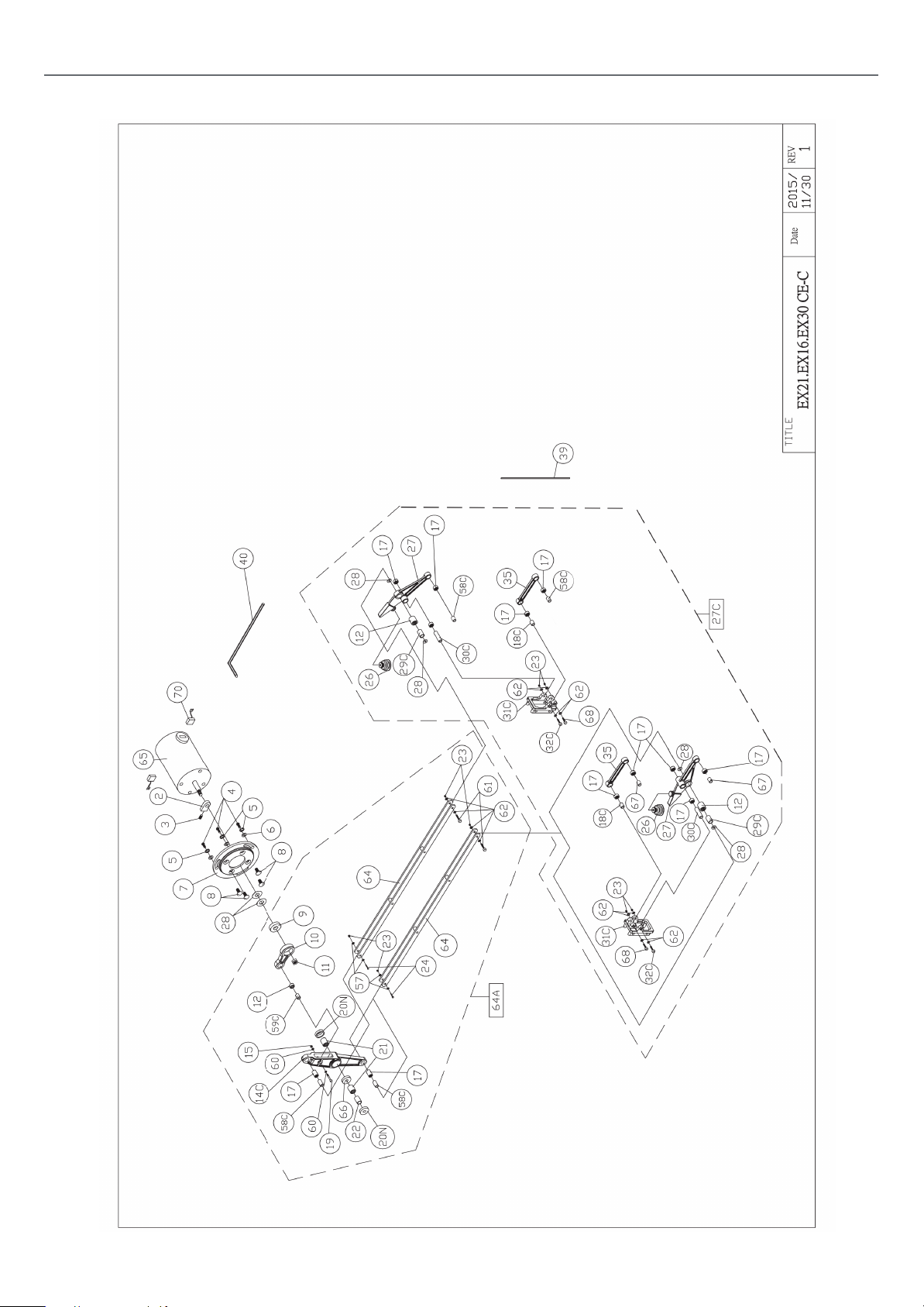
EXPLODED DIAGRAMS/LISTS
KC-16 - KC-21 - Diagram C
(KC-16) (KC-21)
22
Page 23

KC-16 - KC-21 - Diagram C
EXPLODED DIAGRAMS/LISTS
REF. PART NO. DESCRIPTION SPECIFICATION QTY
02 EX21-C02 Balance Block 1
03 EX21-C03 Set Screw M6*6 l
04 EX21-C04 Allen Screw 1/4-20x1/2 3
05 EX21-C05 Lock Washer 1/4. 3
06 EX21-C06 Flat Washer 1/4x16x1.8 3
07 EX21-C07 Motor Cover Plate 1
08 EX21-C08 Screw M6x16 4
09 EX21-C09 Bearing 608ZZ 1
10 EX21-C10 Motor Cam 1
11 EX21-C11 Nut M8XP1.25 LH 1
12 EX21-C12 Bearing 810 3
14C EX21-C14C Rocker Cam 1
15 EX21-C15 Lock Nut M5 1
17 EX21-C17 Bearing 0609 12
18C EX21-C18C Inner Bearing Sleeve
(Short)
19 EX21-C19 Cap Screw M5*28 1
20N EX21-C20N Bearing Cover 2
21 EX21-C21 Bearing 1412 2
22 EX21-C22 Main Rocker Pivot 14. 04x35. 5 1
23 EX21-C23 Nut M4 12
24 EX21-C24 Cap Screw M4*25 2
26 EX21-C26 Air Pump Bellows 2
27 EX21-C27 Front Rocker 2
27C EX21-C27C Upper and Lower
rocker assembly
(EX16-C27C)
EX30-C27C Upper and Lower
rocker assembly
6.03x21 2
28 EX21-C28 Washer M8*15*0.6 6
29C EX21-C29C Inner Bearing Sleeve-
Front Rocker
30C EX21-C30C Bearing Inner Sleeve
(Long)
31C EX21-C31C Rocker Mount 2
32C EX21-C32C Cap Screw M4*45 2
35 EX21-C35 Strut 2
39 EX21-C39 Blade
40 EX21-C40 Allen Key 3MM
57 EX21-C57 Washer M4x10x1 4
58C EX21-C58C Inner Bearing Sleeve
(Long)
59C EX21-C59C Bearing Inner Sleeve 8.03 x 21.5mm 1
60 EX21-C60 Washer M5 2
61 EX21-C61 Cap Screw M4*27 2
62 EX21-C62 Washer M4x14x1 12
64 EX21-C64 Drive link Assy 2
EX16-C64 Drive link Assy 2
EX30-C64 Drive link Assy 2
64A EX21-C64A Complete drive link
Ass’y
EX16-C64A Complete drive link
Ass’y
EX30-C64A Complete drive link
Ass’y
65 EX21-C65 Motor 1
66 EX21-C66 Washer 1
67 EX21-C67 Cylinder insert 6.03x16mm 2
68 EX21-C68 Cap Screw M4x30 2
70 EX21-C70 Motor Brushes 2
8. 03x18. 40mm 2
6.03x37mm 2
6.02 x 16.5mm 4
23
Page 24
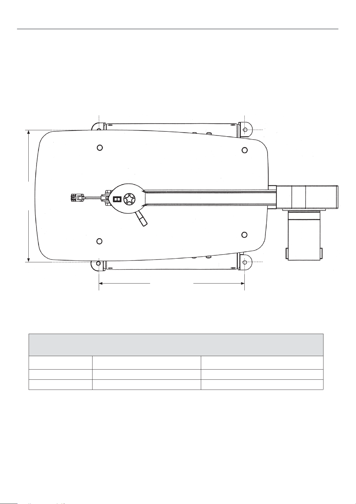
BASE MOUNTING HOLES
Width
Length
Base Hole Dimensions
Model Length Width
AP406SS (KC-16) 262 mm 343 mm
AP535SS (KC-21) 385 mm 343 mm
24
Page 25
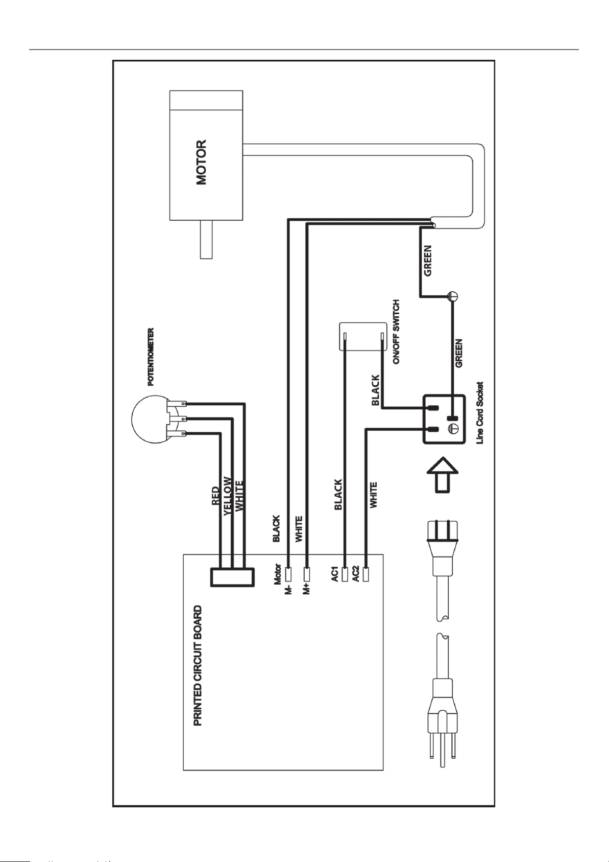
WIRING DIAGRAM
252627
Page 26

Page 27

Page 28

The packaging is suitable for recycling.
Please dispose of it in a responsible manner.
EU Countries Only
Do not dispose of electric tools together with household waste material.
By law they must be collected and recycled separately.
Axminster Tools, Axminster Devon EX13 5PH
axminstertools.com
 Loading...