

Page 1
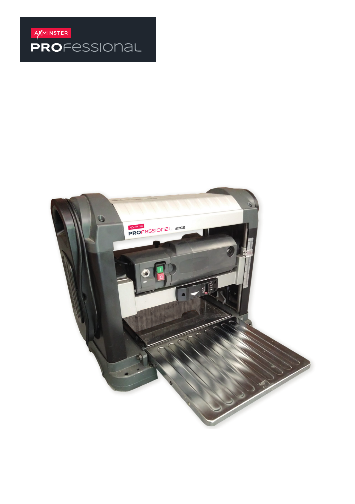
AP330ST
330mm Surface Thicknesser
Code 109100
Original Instructions
AT: 31/07/2025
BOOK VERSION:
02
Page 2
INDEX OF CONTENTS
What’s In the Box 03
Safety 04
Assembly 05-06
Set Up 07-08-09
Operation 10
Blade Rotation/Change 11
Troubleshooting 12
Maintenance 13
Exploded Diagram/Parts LIsts 14-15-16
Wiring Diagram 17
Declaration of Conformity 18-19
2023
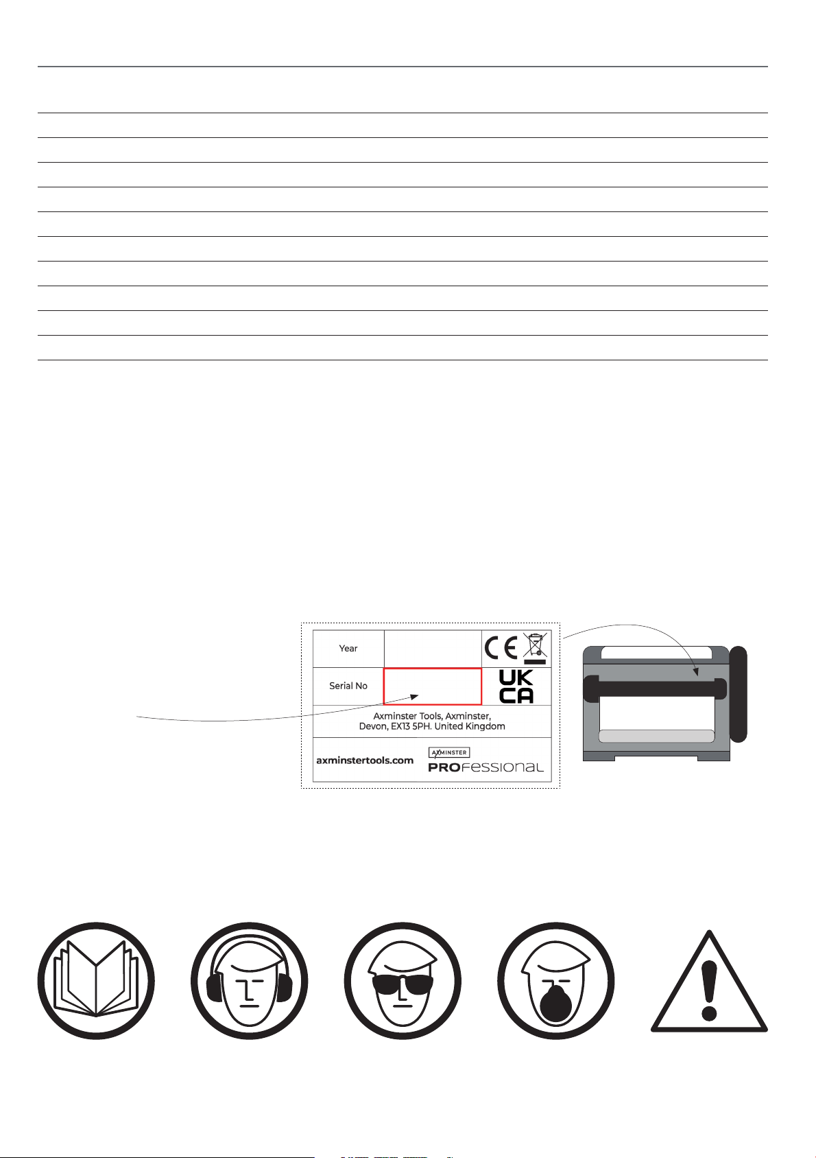
The machine’s Serial Number is
located on the specification label
2003256
as shown.
Rear View
The symbols below advise the correct safety procedures when using this machine.
Fully read manual
and safety instructions
before use
Ear protection
should be worn
Eye protection
should be worn
2
Dust mask
should be worn
HAZARD
Page 3
WHAT’S IN THE BOX
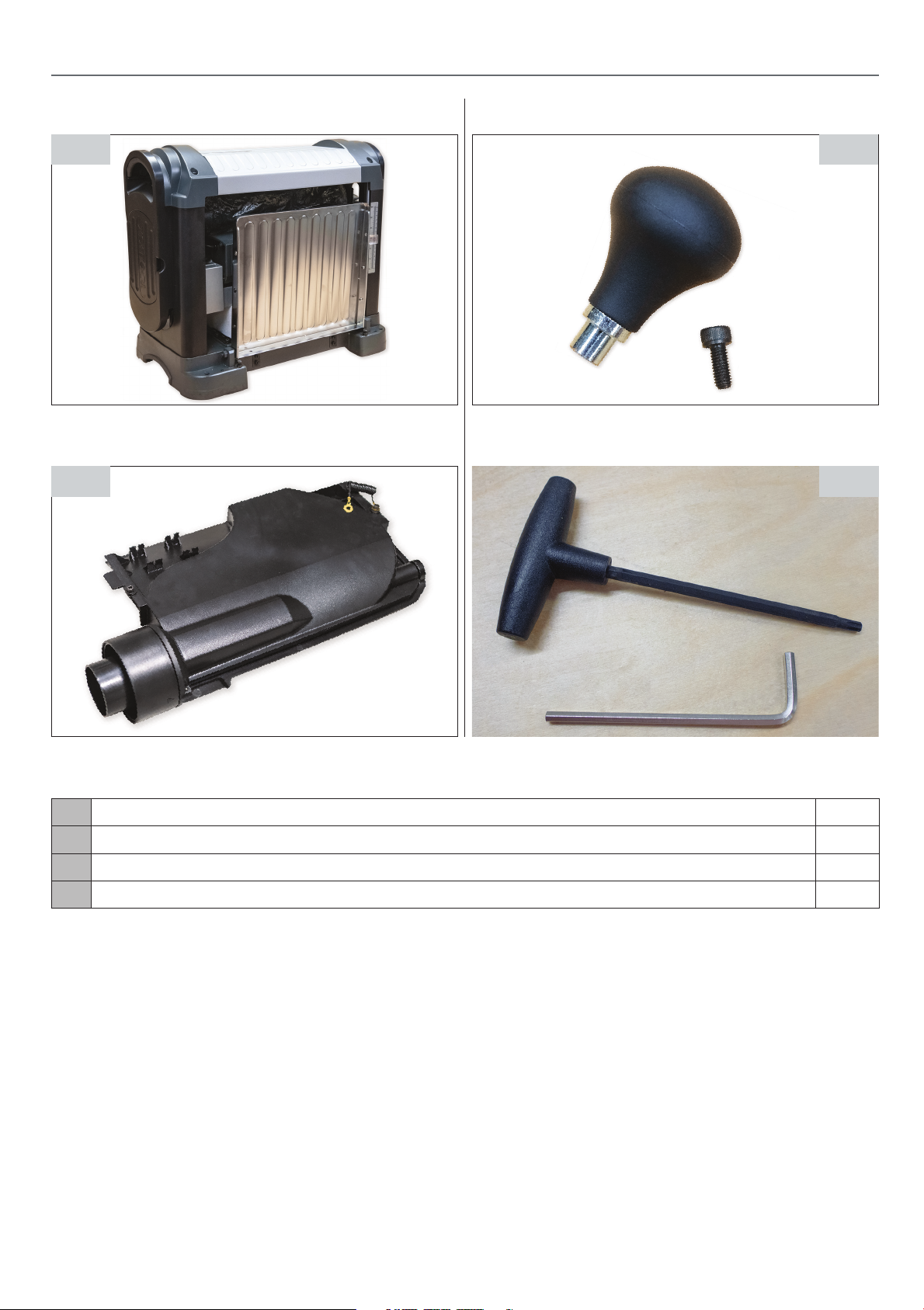
Fig A
Fig C
Fig B
Fig D
A Benchtop Thicknesser 1
B Table Rise & Full Handwheel Knob & Caphead Screw 1
C Dust Extraction Outlet 1
D Handle Torx Screwdriver TZ25 & 4mm Hex Key 1
3
Page 4

SAFETY
The following is a list of safety precautions you must consider when using a Thicknesser:
! ALWAYS REMEMBER TO DISCONNECT THE POWER TO THE THICKNESSER WHEN
MAKING REPAIRS OR ADJUSTING BLADES AND GUARDS.
! ALWAYS REMEMBER TO READ THROUGH THE MACHINE INSTRUCTIONS SUPPLIED.
• Eye protection, ear protection, respiratory protection
and chip extraction are highly recommended when
operating this machine.
• Do not wear gloves, loose clothing, jewellery, or any
dangling objects when operating a Thicknesser and
ensure that long hair is tied up out of the way.
• All guards must be in place and fully operational. If a
guard seems to be missing or damaged, adjust, replace
or repair immediately.
• Ensure that all visible electrical components (cables,
switches) are in good condition without damage.
• Hands and fingers must be kept clear of the blades,
• Use only the recommended blade size & type.
• Ensure all blades are sharp & in good condition.
• The blades must be adjusted in accordance with the
instruction manual.
• Never thickness plane small pieces – 12” in length
minimum.
• Long material should be supported at the same
height as the thicknesser table
• Ensure you are comfortable before you start
work,balanced, not over reaching.
• Do not use the machine if you are under the
influence of drugs or alcohol, tired or distracted.
• Do not allow children to operate the machine.
• Do not use the machine in an excessively damp or
wet environment.
• Never leave the machine unattended when it is
running.
• Keep the table top & surrounding work area free
from excessive dust & debris to help prevent slipping
or tripping.
• Ensure that the machine is stable on the floor, fixed
to the bench and wheel bases if used are locked off.
More safety information can be found at: http://www.hse.gov.uk/pubns/wis17.pdf
4
Page 5
ASSEMBLY
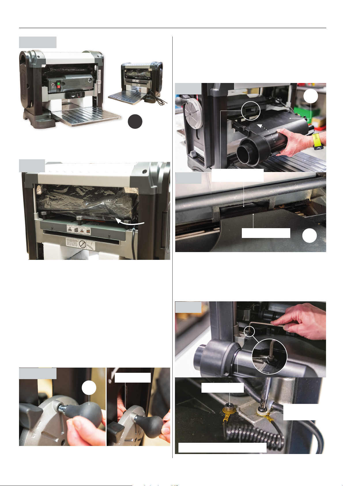
Fig 01-02
A
1. Place the thcknesser (A) on a flat and lever surface and
fold both front & rear extention tables down, see fig 01-02.
Fig 03
5. Find the dust extraction hood. Slide the extractor (C)
into the space that occupied the cutter block housing
see fig 06. Gently push home until the extractor inlet
slots over the motor’s fan outlet, see fig 07. Secure in
place using the two Cap screws on either side of the
extractor moulding, see fig 08.
Fig 06
C
Fig 07
Motor fan outlet
2. Remove all accessories parts from inside the machine,
see fig 03.
3. Locate the rise and full handwheel knob and caphead
screw (B). Rotate the rise & full wheel to the side of the
thicknesser until the threaded hole in the wheel is in
line with the elongated slot in the frame.
4. Inset the knob (B) into the holes recess in the wheel
assembly, introduce the Cap screw through the
elongated slot from inside the machine and secure
th
e knob in place using the supplied 4mm Hex key,
see fig 04-05.
Fig 04-05
Cap screw
B
Extractor inlet
NOTE: Dust and debris moving inside the plastic extraction hose may cause a build up of static electricity.
This can cause a potential hazard especially with fine
dust. The extraction outlet incorporates a ‘Anti-Static’
discharge cable. Secure the connector to the frame
using the power cable P-Clip, see fig 08.
C
Fig 08
Cap screws
Anti-Static distcharge cable
5
Power cable
P-Clip
Continues over...
Page 6
ASSEMBLY
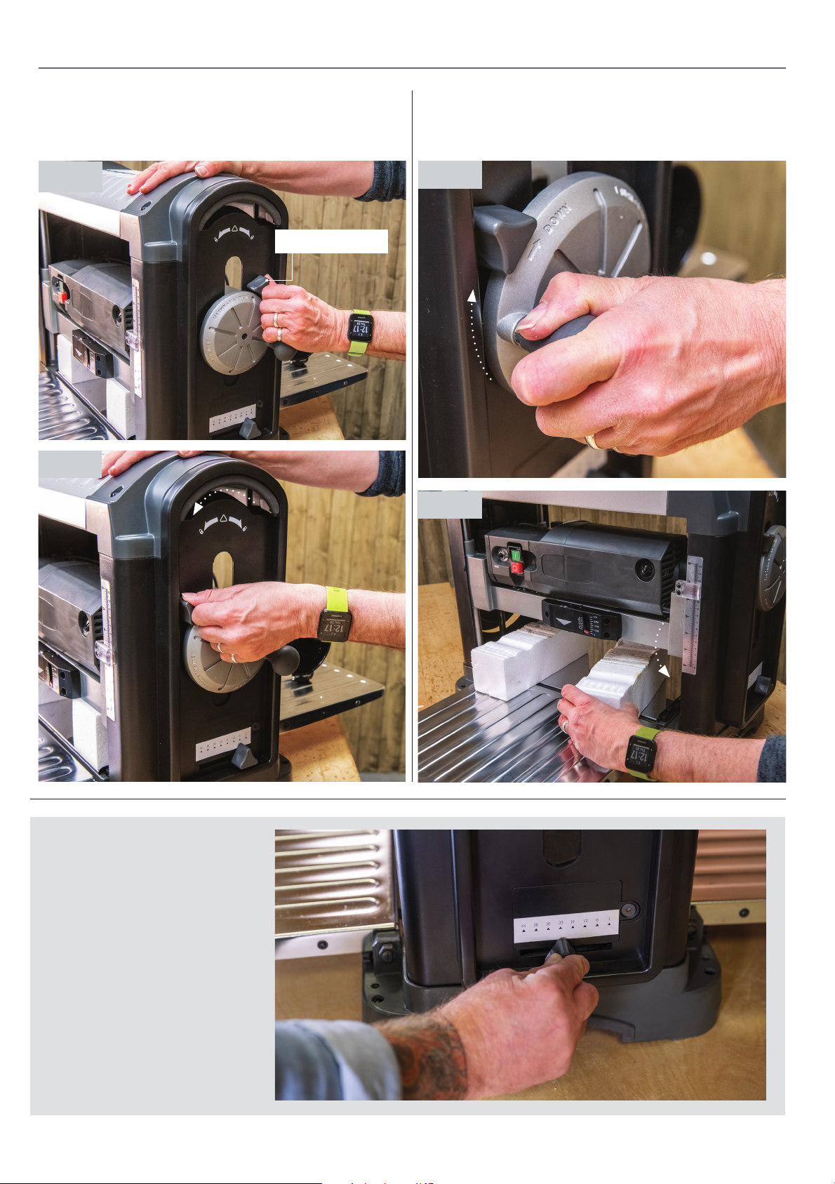
7. Unlock the cutter block head unit by rotating the
locking lever to the left, Note: this is located above
the rise and full handwheel, see fig 09-10.
Fig 09
Locking lever
Fig 10
8. Turn the rise and full wheel clockwise to raise the
head sufficiently to remove the polystyrene blocks,
see fig 11-12.
Fig 11
Fig 12
8 Pre-Set Depth Stop
Save time on setup with 8 preset depth stops at the following
common timber thicknesses:
3.2mm, 6.35mm, 12.7mm, 19mm,
25.4mm, 31.75mm, 38mm and
44.5mm
6
Page 7
SET UP
Levelling the Tables
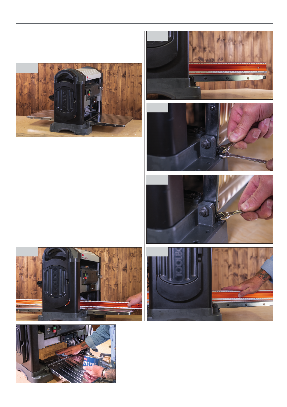
For storage & transportation the infeed & outfeed support
tables are folded in the up position, for use these tables
will need to be folded down, see fig 13.
Fig 13
Before use the table will need to be levelled with the main
planer table.
1. Ensure that the planer is disconnected from
its power source
2. Fold both tables down.
3. Place a straight edge / clean spirit level through
the planer & rest it on the tables, see fig 14
Fig 15
Fig 16
Fig 17
4. Check to see if there are any large gaps underneath
the straight edge, see fig 15
5. To reduce the gaps & align the tables first lift the
tables & release the lock nuts, see fig 16
6. Adjust the stop screw until the folded support table
appears level with the main planer table,repeat both
sides for both the infeed & out feed tables, see fig 17-18
Fig 14
Fig 18
Ensure that the tables are
cleaned and waxed ready
for the first use
7
Continues over...
Page 8
SET UP
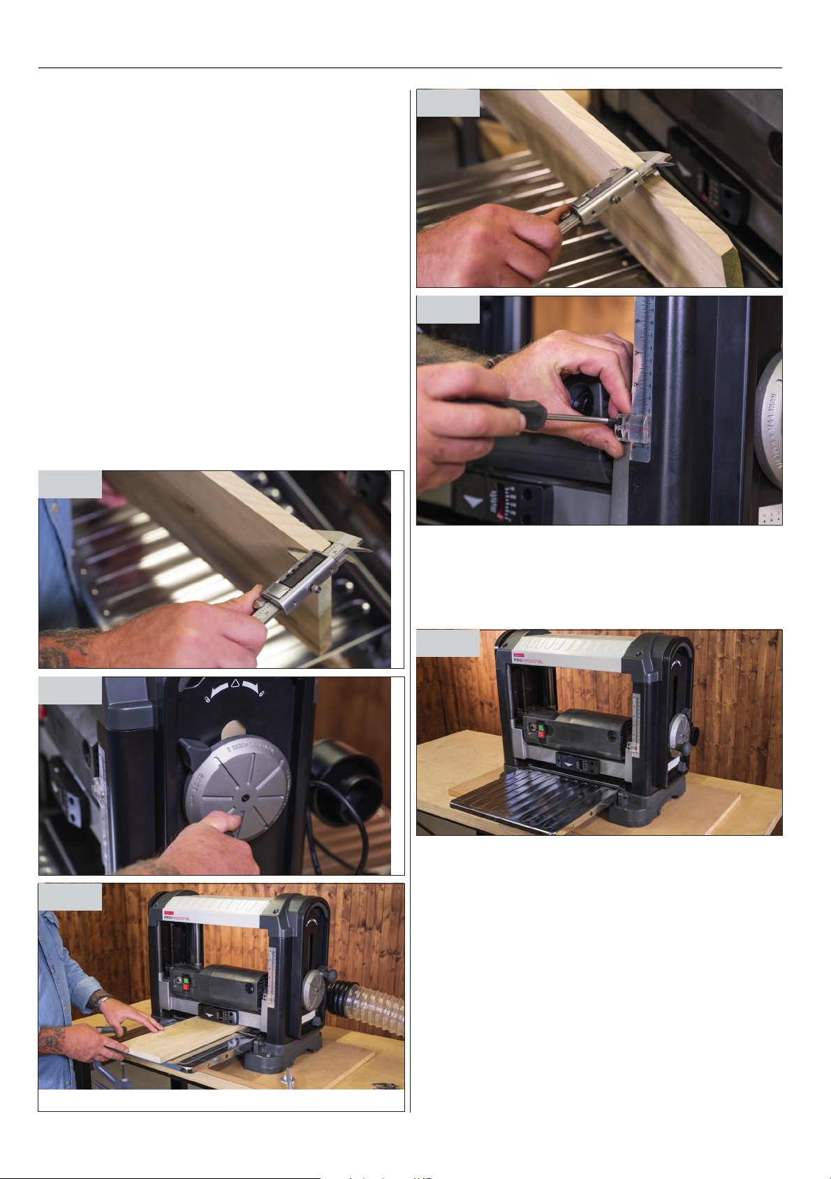
Setting the Timber Thickness Scale
1. Using a scrap fairly flat piece of timber, measure the
thickness of the timber at each corner, see fig 19
2. Ensure that the cutter head is unlocked, then adjust
the cutter head height to match your timber
measurement then relock the cutter head, see fig 20.
3. Switch ‘ON’ the thicknesser and wait until it
reaches full speed.
4. Feed a piece of timber through as per operation
instruction on page 9, see fig 21.
5. Switch ‘OFF’ and wait until it comes to a complete stop.
6. Compare the measurement on the timber with the
reading on the scale, see fig 22.
7. If the reading is different, adjust the scales pointer by
loosening the two screws & moving the scale, see fig 23.
Fig 19
Fig 22
Fig 23
Fig 20
Fig 21
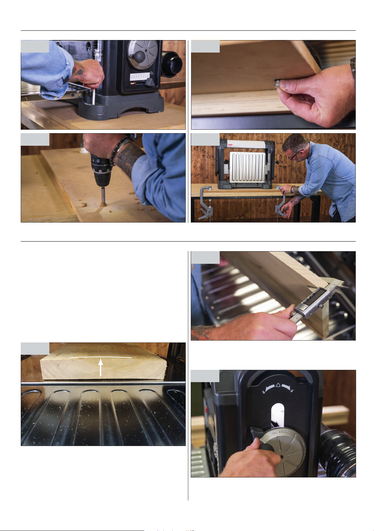
Securing to the Workbench
It is recommended to secure the planer to the workbench
when in use, for this we suggest mounting your planer to
a baseboard, see fig 24.
Fig 24
1. Choose a board around 50% larger than the planers
footprint / base size & at least 16mm thick.
2. Position the planer central to the baseboard & mark
the four mounting holes in the planer base, see fig 25.
3. Drill the four holes to suit the bolts using ( 70mm x
M8 recommended), to ensure that the board sits flat &
stable on the workbench or trestles counter bore the
holes slightly from the underside, see fig 26.
4. Fix the planer to the baseboard , bolting from
the underside, see fig 27.
5. Then simply clamp the baseboard & planer to the
workbench or trestle, see fig 28.
8
Page 9
SET UP
Fig 25
Fig 26
Fig 27
Fig 28
Before using the machine you must ensure that the
machine has been set up with the tables levelled & the
scale set. Also ensure that the tables are clean, waxed
and the extractor has been connected.
For the best results it is advisable to have the flattest side
of the timber facing down on the table. If a satisfactory
“flat” side cannot be found then it may be wise to flatten
off one side with either a surface planer or hand plane.
If the timber seems to be crowned then feed the timber
through crown up, see fig 29.
Fig 29
OPERATION
Fig 30
2. Set the thicknesser cutter head to this dimension using
the depth scale on the side of the machine and lock it off,
see fig 31.
Fig 31
1. Measure the largest/thickest section of the timber,
check this at all four corners of the timber, see fig 30.
9
Continues over...
Page 10
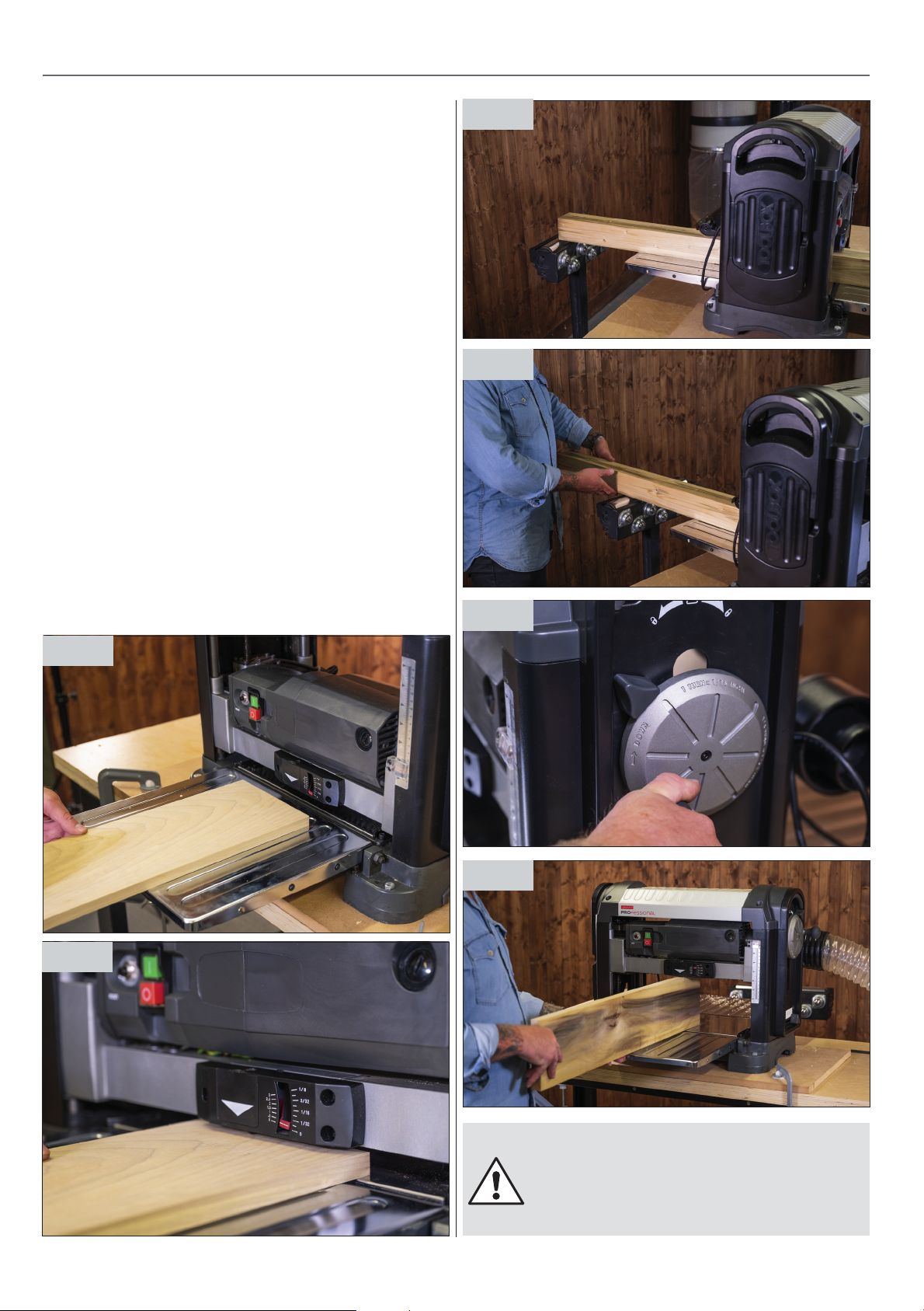
OPERATION
3. Press the green “on” button & wait for the machine
to come up to full speed.
4. Place the timber on the infeed table & slowly advance
the timber towards the cutter head, see fig 32.
5. The depth of cut scale will give you an indication of
how much material will be removed, see fig 33.
6. Allow the machine to pick up the timber & pull it
through the cutter head, ensure that long lengths
of timber are supported, see fig 34.
7. Move to the rear of the machine to support the timber
as it is fed through the cut, do not pull it through, allow
the feed rollers to feed the timber through, see fig 35.
8. The first pass will only very lightly contact the timber,
to remove more timber & completely it clean up then
simply wind the head down, see fig 36.
9. Once the first side is clean & planed then flip the
timber over to plane the other side taking it down
incrementally down to your desired width.
Fig 34
Fig 35
10. It is perfectly ok to thickness the narrow edge of
the timber, a minimum of 20mm is recommended,
see fig 37.
Fig 32
Fig 33
Fig 36
Fig 37
10
IT IS IMPORTANT NOT TO OVERLOAD THE
PLANER, FOR HARDWOODS & WIDE TIMBER
BOARDS 150MM+ IT IS RECOMMENDED TO
REDUCE THE DEPTH CUT FOR EACH PASS
DOWN TO 0.5MM 1MM.
Page 11
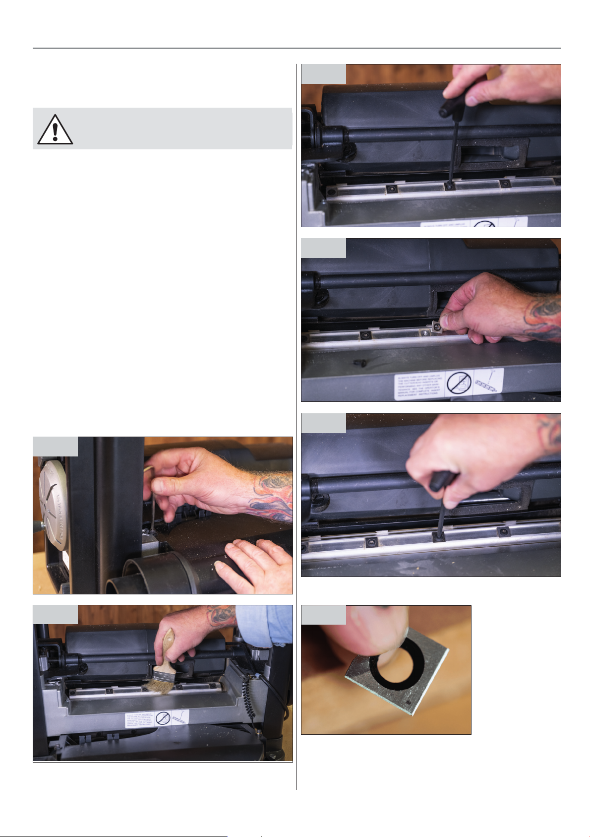
BLADE ROTATIONCHANGE
There are 26 HSS square cutters in total each with 2 cutter
edges across the 330mm cutting width, after many hours
of use these cutters will need rotating or replacing
DISCONNECT THE MACHINE FROM THE
MAINS SUPPLY BEFORE CONTINUING!
1. Undo the 2 cap screws and remove the plastic
extraction chute, see fig 38.
2. Brush all debris from the cutter/cutters that are to
be rotated or changed, see fig 39.
3. Using only the tool provided undo the countersink
Torx screw, see fig 40.
4. Lift & twist the cutter so that the fresh sharp edge faces
downwards, ensuring that there is no debris under the
cutter & the cutter is seated correctly, see fig 41.
5. Retighten the countersink Torx screw & repeat if
numerous cutters seem blunt or damaged, see fig 42.
6. NB - Each cutter has a rotation marker to help you
monitor which edges have been used - NB the cutting
edge & marker will always face down, see fig 43.
Fig 40
Fig 41
7. Replace the dust chute
Fig 38
Fig 39
Fig 42
Fig 43
11
Page 12

TROUBLESHOOTING
PROBLEM POSSIBLE CAUSE SOLUTION
Grain is fussy 1. Planing wood with high
moisture content
2. Blades are dull
Grain is torn 1. The cut is too heavy
2. Blades are cutting
against the grain
3. Blades are dull
Grain is rough/raised 1. Blades are dull
2. Cut is too heavy
3. Moisture content is too high
4. Cutter head bearings are
damaged
Uneven depth of cut
from side to side
Board thickness
does not match
depth of cut scale
Chain is jumping 1. Sprockets are misaligned
1. Blade projection is not uniform
2. Cutter head is not levelled
to planer bed
1. Depth of cut scale is incorrect 1. Adjust the depth of cut scale
2. Sprockets are worn
1. Dry the wood
2. Sharpen the blades
1. Review proper depth of cut
2. Feed the workpiece with the
grain, or turn workpiece around
3. Sharpen the blades
1. Sharpen the blades
2. Review proper depth of cut
3. Dry the wood
4. Replace the bearings
1. Adjust the blade projection
2. Level the cutter head to table
1. Align the sprockets
2. Replace the sprockets
Machine will not
start/restart
Circuit tripping
resulting in motor
stoppage
Poor feeding
of timber
Workpiece
is jammed
1. Tool is not plugged in
2. Motor failure
3. Wire is loose
4. Overload reset has failed
5. Motor starter failure
1. Extension cord is too long
or too thin
2. Blades are too dull
3. Low voltage running
1. Planer table is dirty
2. Feed roller is damaged
3. Sprocket is damaged
4. Gear box malfunctions
1. Inadequate blade setting height 1. Set the blade to the correct height
1. Check the power source
2. Check the motor
3. Check the motor by a qualified
electrician
4. Allow machine to cool down
and restart
5. Check the motor by a qualified
electrician
1. Use a shorter or thicker
extension cord
2. Sharpen or replace the blades
3. Check the voltage
1. Clean off the pitch and residue,
and lubricate the planer table
2. Replace the feed roller
3. Replace the sprocket
4. Check the gear box
12
Page 13
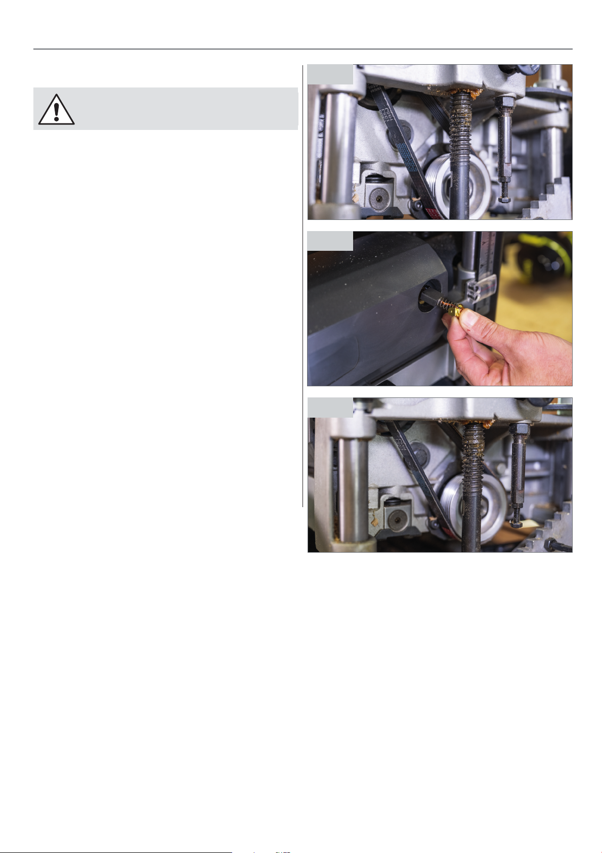
DISCONNECT THE MACHINE FROM THE
MAINS SUPPLY BEFORE CONTINUING!
• Clean tables ensuring that they are pitch /
resin free & level.
• Check that the cutters & feed rollers are
clean & free of debris
MAINTENANCE
Fig 44
• Check cutters.
• Check power lead.
• Check drive belt, see fig 44.
• Check carbon brushes, see fig 45.
• Check & regrease elevating screws, see fig 46.
Fig 45
Fig 46
13
Page 14
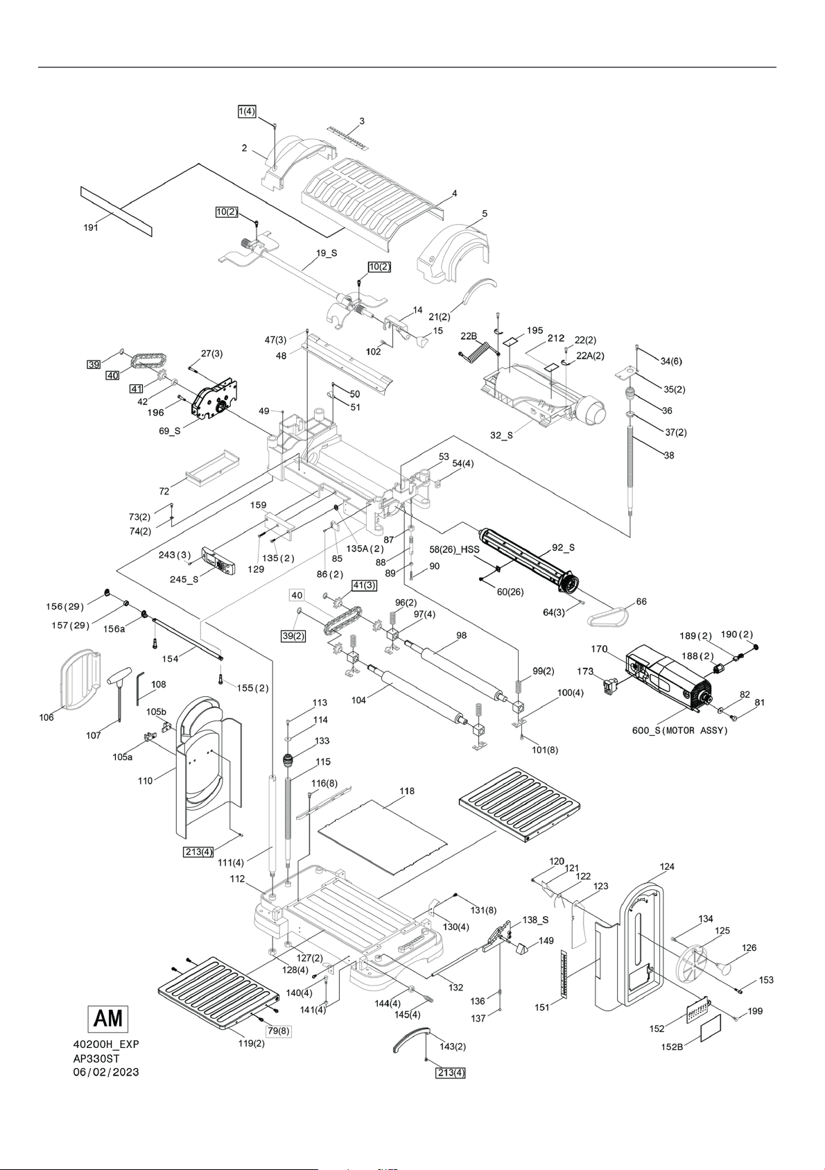
EXPLODED DIAGRAMPARTS LISTS14EXPLODED DIAGRAMPARTS LISTS
Page 15

NO DESCRIPTION QTY
1 SCR SEMS L/WASH 4
2 CAP LEFT 1
3 SCALE LENGTH 1
4 COVER UPPER 1
5 CAP RIGHT 1
6 SHAFT TRANSMISSION 1
7 WASHER 1
8 NUT LOCK 1
9 SUPPORT 2
10 SCR SEMS L/WASH 4
11 WASHER 1
12 SCR SOC SET CUP PT 2
13 WORM ELEVATION 1
14 HANDLE 1
15 KNOB SNIPE 1
16 SCR HEX SOC HD LOCK 1
17 RING RETAINING 1
18 PLATE LOCK LEFT 1
19 SLEEVE 1
20 PLATE LOCK RIGHT 1
21 PAD UPPER 2
22 M5XP0.8X12L 2
22A SBG4910-216d 2
22B ANTISTATIC DISCHARGE CABLE 1
27 SCR SEMS L/WASH 3
28 SCR SEMS L/WASH 2
29 COVER GEARBOX OUTSIDE 1
30 BEARING BALL 1
31 SHAFT GEAR 1
32 DUST CHUTE 1
34 SCR HEX SOC HD LOCK 6
35 COVER 2
36 WORM GEAR R.H. 1
37 BUSHING 2
38 SCREW ELEVATING R.H. 1
39 RING RETAINING EXT 3
40 CHAIN 2
41 SPROCKET 4
42 SPACER 1
43 GEAR ASM SMALL 1
43a GEAR DRIVE 2
44 GEAR ASM INTER 1
45 SPACER UNDERCUT 4
46 SPACER 2
47 SCR PAN CR 3
48 PLATE DUST CHUTE 1
49 SCR HX SOC SET CUP 1
50 SCR PAN CR 1
51 CLAMP CORD 1
53 FRAME UPPER 1
54 BLOCK SUPPORT 4
58 INSERT 26
60 TORX SCREW 26
61 KEY 1
63 RETAINER BEARING 1
64 SCR HEX SOC CAP 3
65 PULLEY CUTTER HEAD 1
66 BELT DRIVE 1
67 GEAR LARGE 1
68 BUSHING GEAR 5
69 COVER GEARBOX INSIDE 1
70 GEAR PINION 1
71 BEARING BALL 2
72 COVER GEAR BOX 1
73 SCR PAN CR TYTT 2
74 LOCKWASHER EXT 2
75 NUT 1
78 BUSHING 1
79 SCR SEMS W/WASH 9
80 COVER POINTER 1
81 SCREW HEX HD 1
82 WASHER 1
84 ROD POINTER ELEVATING 1
85 INDICATOR DEPTH 1
86 SCREW PAN CR 2
87 NUT HEX SPECIAL 1
88 ROD STEP 1
89 NUT HEX 1
90 SCRW HEX HD 1
92 CUTTERHEAD 1
93 WORM GEAR L.H. 1
94 PULLEY MOTOR 1
95 NUT HEX 1
96 SPRING COIL LEFT 2
97 BLOCK BEARING 4
98 ROLLER OUTFEED 1
99 SPRING COIL RIGHT 2
100 PLATE RETAINER RIGHT 4
101 SCR HEX SOC CAP 8
102 SCR HEX SOC CAP 1
104 ROLLER INFEED 1
105a HOLDER TOOL A 1
105b HOLDER TOOL B 1
106 COVER TOOL BOX 1
107 TORX WRENCH 1
108 WRENCH HEX’L 1
110 COVER SIDE LEFT 1
15
Page 16

EXPLODED DIAGRAMPARTS LISTS
111 ROD SUPPORT 4
112 BASE 1
113 SCR HEX SOC CAP 1
114 WASHER 1
115 SCREW ELEVATING L.H. 1
116 SCR SEMS L/WASH 8
117 RAIL GUIDE 2
118 PLATE WEAR 1
119 INFEED OUTFEED TABLE 2
120 SCR PAN CR TYTT 1
121 PLATE STIFFENER 1
122 SPRING TORSION 1
123 PLATE SIDE GUARD 1
124 COVER SIDE RIGHT 1
125 HUB HANDWHEEL 1
126 KNOB HANDWHEEL 1
127 NUT LOCK 2
128 NUT HEX 4
129 SCREW 1
130 SPRING FLAT 4
131 SCR SEMS L/WASH 8
132 ROD PIVOT 1
133 WORM GEAR L.H. 1
134 SCR HEX SOC CAP 1
135 SCREW 2
135A TH-bx330p 135a 6
136 SPRING COIL 1
137 BALL STEEL 1
138 BLOCK GUARD 1
139 SCR HEX SOC CAP 2
140 SCREW HEX 4
141 NUT HEX 4
143 PAD BASE 2
144 NUT HEX SPECIAL 4
145 BOLT ADJUSTING 4
146 BLOCK STEP 1
147 NUT HEX 1
148 PIN STEP BLOCK 1
149 KNOB STEP 1
151 SCALE THICKNESS 1
152 COVER SIDE R.H. 1
153 SCR SEMS L/WASH 1
154 LONG BAR 1
155 SCR HEX SOC CAP 2
156 SPACER 29
156a SPACER 1
157 ANTI-KICK JAW 29
159 PAD 1
196 SCR SEMS L/WASH 1
199 SCR HEX SOC FLT HD 1
213 SCR PAN CR TYTT 8
214 WASHER 3
215 COVER GEARBOX 1
216 WASHER WAVE 1
217 PLUG 1
222 WASHER WAVE 1
243 SCREW 3
245 HOUSING POINTER 1
246 SPRING COIL 1
248 POINTER 1
600 MOTOR 1
188 HOLDER BRUSH 2
189 BRUSH 4
190 CAP BRUSH 2
172 WAVE FILTER 1
173 SWITCH LOCKING 1
16
Page 17
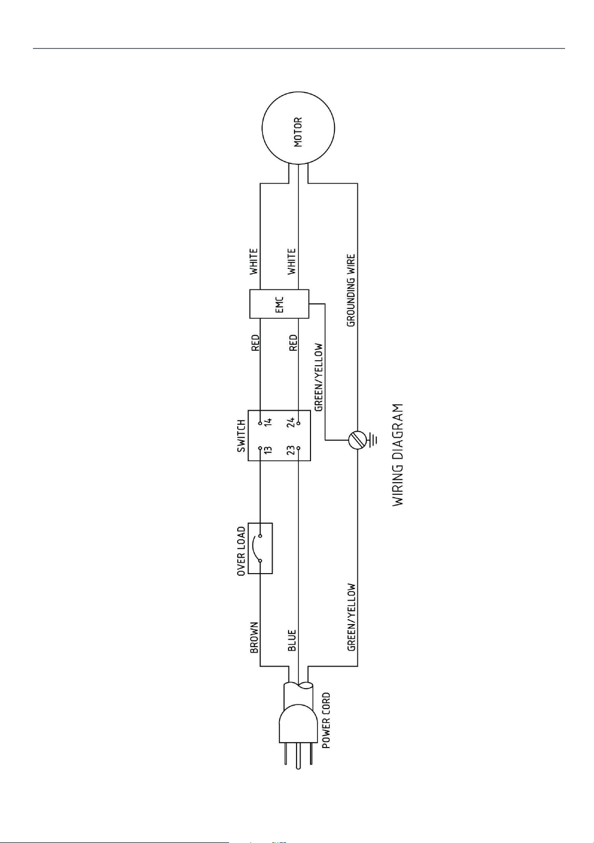
WIRING DIAGRAM
17
Page 18
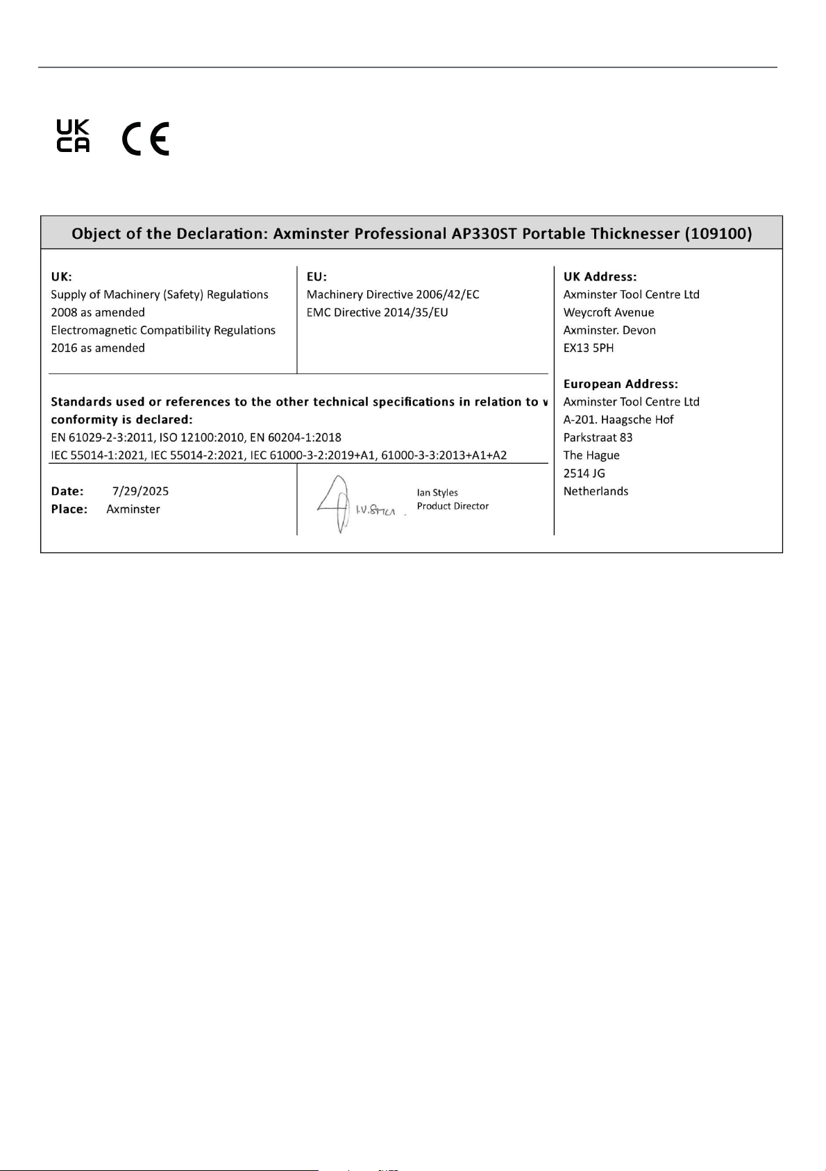
DECLARATION OF CONFORMITY
18
Page 19

19
Page 20

The packaging is suitable for recycling.
Please dispose of it in a responsible manner.
EU Countries Only
Do not dispose of electric tools together with household waste material.
By law they must be collected and recycled separately.
Axminster Tools, Axminster Devon EX13 5PH
axminstertools.com
 Loading...