

Page 1
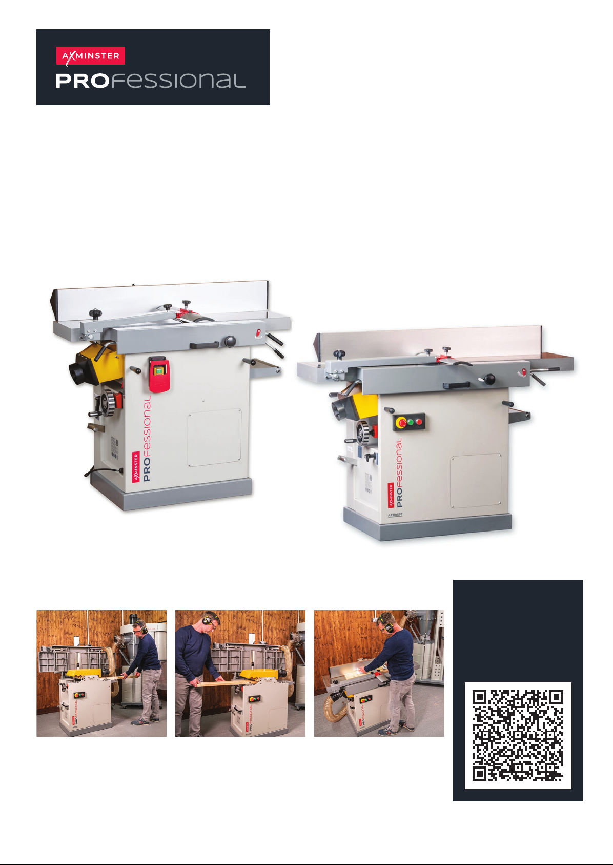
AP260SPT Code 107807
AP310SPT Code 107808
AP260SPT & AP310SPT
Planer Thicknesser
Original Instructions
AP260SPT
AP310SPT
Watch
The Set Up
Guide
Here!
AT: 13/08/2025
BOOK VERSION:
07
Page 2
INDEX OF CONTENTS
What’s In The Box 02-03
Safety 04
Assembly 05-06-07
Set Up 08-09
General Use / Operation 10-11-12-13
Troubleshooting 14
Maintenance/Blade Change 15-16
AP260SPT Exploded Diagram/Parts Lists 17-24
AP310SPT Exploded Diagram/Parts Lists 27-36
Wiring Diagram 27
Declaration of Conformity
WHAT’S IN THE BOX
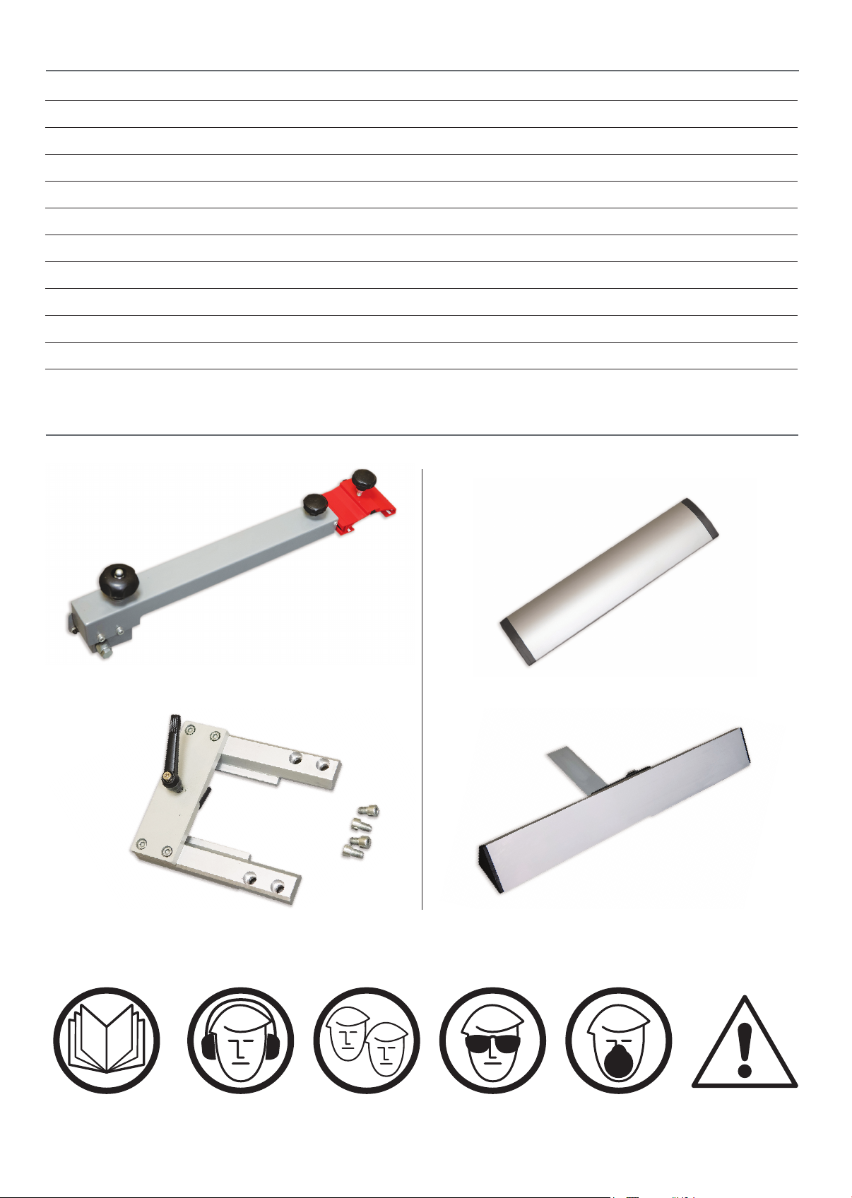
Fig A
Bridge Guard Arm
Fig C
39
Fig B
Bridge Guard
Fig D
Fence Bracket
Fence
The symbols below advise the correct safety procedures when using this machine.
Fully read manual
and safety instructions
before use
Ear protection
should be worn
Two Man
Assembly
2
Eye protection
should be worn
Dust mask
should be worn
HAZARD
Page 3
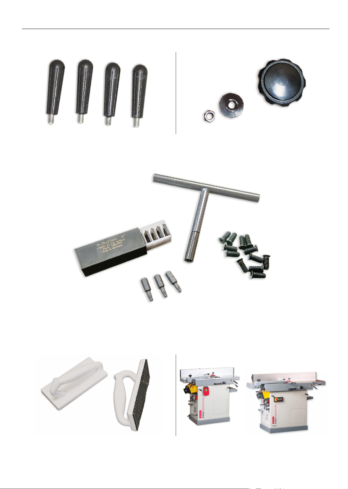
Fig E
Fig F
WHAT’S IN THE BOX
Carrying Handles & Table Locking Knob
Fig G
Replacement Cutters & Screws and Cutter Changing Spanner
Push Pad Guide Blocks
3
Planer Thicknesser
Fig H
Page 4

SAFETY
The following is a list of safety precautions you must consider when using a Planer/Thicknesser:
ALWAYS REMEMBER TO DISCONNECT THE POWER TO THE PLANERTHICKNESSER
WHEN MAKING REPAIRS OR ADJUSTING BLADES AND GUARDS.
ALWAYS REMEMBER TO READ THROUGH THE MACHINE INSTRUCTIONS SUPPLIED.
• Eye protection, ear protection, respiratory protection and chip extraction are highly recommended when
operating this machine.
•
Do not wear gloves, loose clothing, jewellery, or any dangling objects when operating a planer and ensure
that long hair is tied up out of the way.
• All guards must be in place and fully operational. If a guard seems to be missing or damaged,
adjust,replace or repair immediately.
• Ensure that all visible electrical components (cables, switches) are in good condition without damage.
• Hands and fingers must be kept clear of the blades - push blocks are highly recommended.
• Use only the recommended blade size & type.
• Ensure all blades are sharp & in good condition.
• The blades must be adjusted in accordance with the instruction manual.
• Never thickness plane small pieces - 12” in length minimum.
• Long material should be supported at the same height as the planer or thicknesser table.
• Ensure you are comfortable before you start work, balanced, not over reaching.
• Do not use the machine if you are under the influence of drugs or alcohol, tired or distracted.
• Do not allow children to operate the machine - without adult supervision.
• Do not use the machine in an excessively damp or wet environment.
• Never leave the machine unattended when it is running.
• Keep the machine table and surrounding work area free from excessive dust & debris to help prevent
slipping or tripping.
• Ensure that the machine is stable on the floor and wheel bases are locked off.
• More safety information can be found at: http://www.hse.gov.uk › pubns › wis17
4
Page 5
Fitting the Carrying Handles
ASSEMBLY
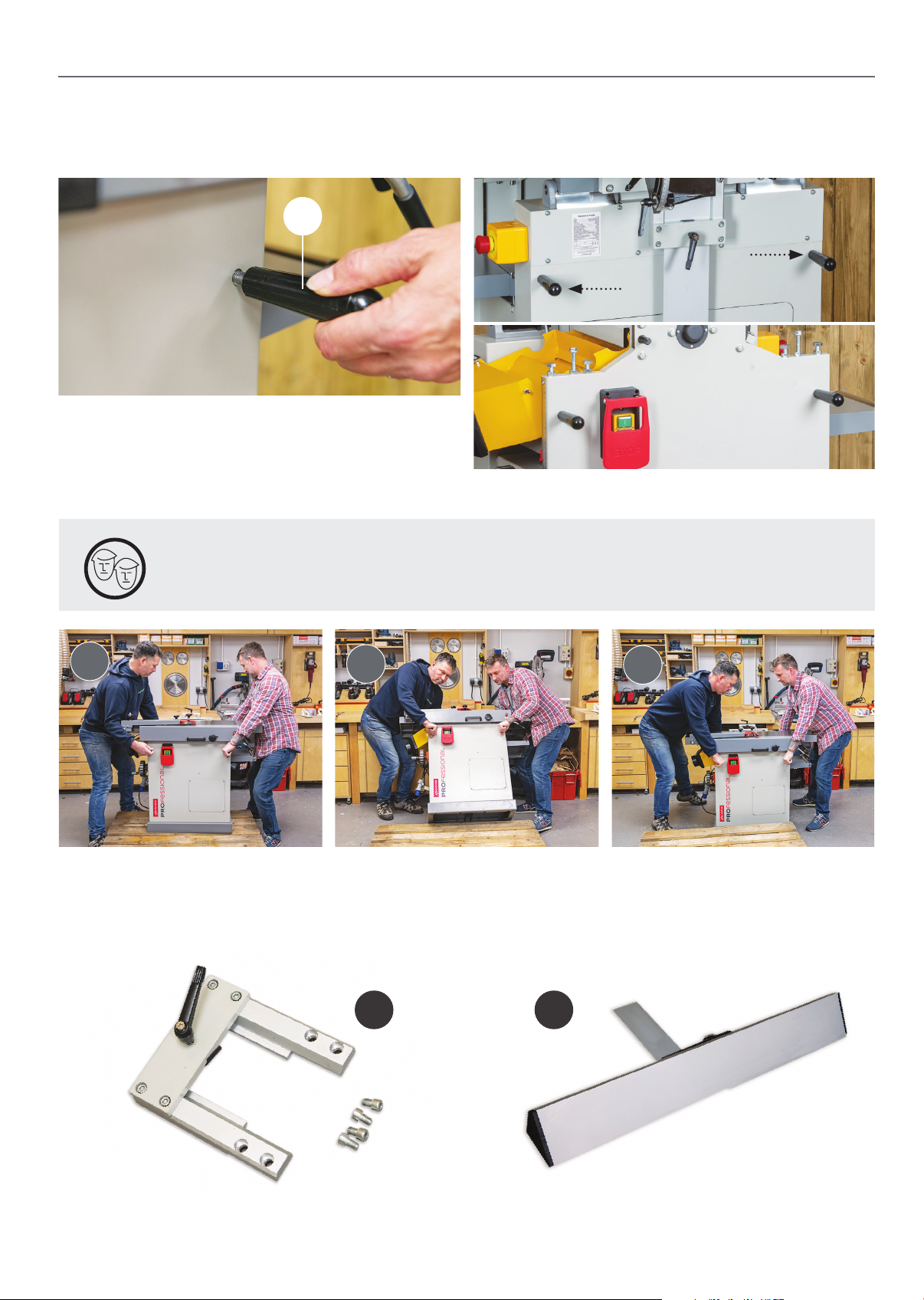
Fig 01
E
Screw the four carrying handles (E) into the
threaded holes on either side of the machine
as shown above, see fig 01-02
Removing Machine from Pallet
DO NOT LIFT BY THE TABLES WHEN REMOVING THE MACHINE FROM THE PALLET
USE THE FOUR CARRYING HANDLES AS SHOWN !
Fig 02
1
Fitting the Bracket & Fence Assembly
Fig 03
2
3
Fig 04
DC
5
Continues over...
Page 6
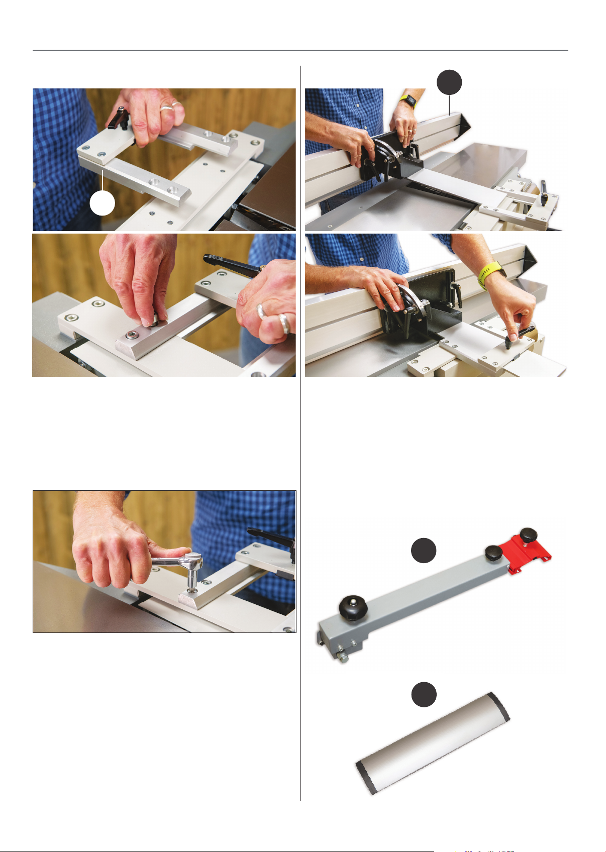
ASSEMBLY
Fig 05-06
Fig 08-09
D
C
1. Line up the bracket (C) with the four holes on
top of machine, see fig 05.
2. Use the four cap head bolts to secure, see fig
06.
Fig 07
3. Tighten with a 6mm hex key, see fig 07.
Fitting the Fence Assembly
1. Slide the fence (D) into the fence bracket (C),
see fig 08.
2. Secure the fence with the locking handle,
see fig 09.
Bridge Guard Arm & Guard Cover Assembly
Fitting the bridge guard arm (A) and bridge guard
(B), level/parallel with the outfeed table, see fig 10-11
1. Slide the Hex head bolt & spacer through the hole
to the end of the bridge guard arm (A), see fig 12.
Fig 10-11
A
B
6
Page 7

ASSEMBLY
Fig 12
2. Towards the back of the outfeed table attach the
bridge guard arm (A) in the threaded hole to the
side of the table, see fig 13.
Fig 13
4. Fit Nyloc nut under table to the end of the
hex head bolt used to attached the bridge
guard arm, see fig 15.
5. Tighten with a 16mm spanner, fig 16.
6. Slide the bridge guard (B) into place and
secure in place with locking knob, see fig 17-18.
Fig 17-18-19
Fig 14
3. Tighten hex head bolt, see fig 14
Fig 15-16
Nyloc nut
Fitting the Infeed Table Height
Adjustment Locking Knob
Fig 20-21-22
1. Place the washer on stud as shown, see fig 21
2. Fit the clamping knob on to stud, see fig 22.
7
Page 8
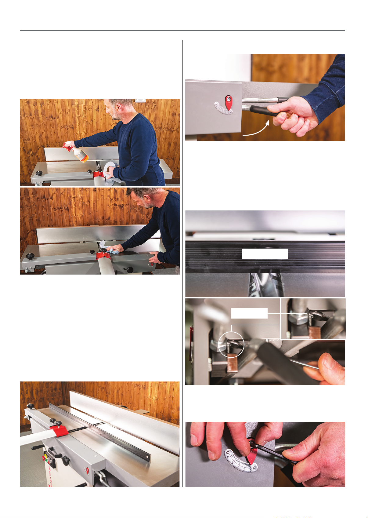
SET UP
• Ensure that the machine has sufficient space
around it to fully function & is stable on the
floor & the wheel kit is locked off. Degrease tables
& cutterblock - recommended is the Liberon wax &
polish remover, see fig 23-24.
Fig 23-24
Fig 26
• Raise the infeed table up to meet the underside
of the straight edge, see fig 26 this should come to
a positive stop bringing both tables level with each
other. If the infeed table stops higher or lower than
the outfeed table then adjustment can be made via
the bolt stop, see fig 27-28.
Fig 27-28
Tables, Level & Set Scales
• Firstly let’s set up the planing (top) parts of the
machine, the tables including the depth of cut
scale & the all important fence.
• Place a straight edge or clean spirit level at least
3ft long on the outfeed table, ensure that it is in the
middle of the table and is just off centre towards the
outfeed table, see fig 25.
Fig 25
Straight edge
Bolt stop
• Once the infeed and outfeed tables are level then
set the pointer to zero on the scale, see fig 29.
Fig 29
8
Page 9
SET UP
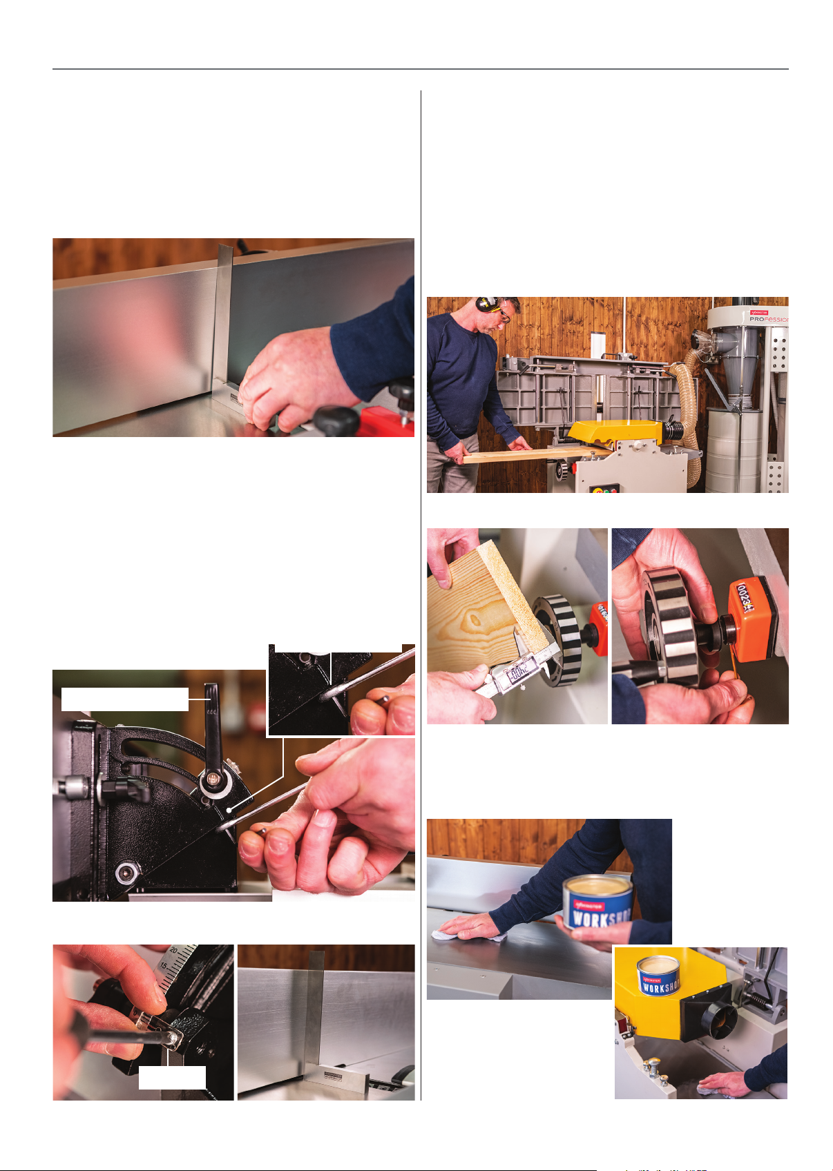
Thicknesser ScaleFence Set Up
• Position the fence around half way across the
table & lock in place. Then place a reliable square
on the table & against the fence, just beyond the
cutterblock, see fig 30.
Fig 30
• Check to see if the fence is square (90deg) to
the table, if not adjustments are made by firstly
unlocking the fence tilt clamp handle, then slacken
the adjuster screw lock nut, see fig 31. If a gap is at
the top of the square then wind the adjuster screw
out, if the gap is at the bottom then wind the
adjuster screw in. Ensure that all is locked in place
once adjustments have been made then set the
pointer to zero, see fig 32-33.
• Following the planing/thicknessing operation
instructions on page 10. Machine a piece of timber
so that it has two clean & parallel faces, at this point
leave the thicknessing table locked in position, see
fig 34. Accurately measure the dimension of the
timber across those faces then set both the digital
scale & pointer scale to that dimension, see fig 35-36.
Fig 34
Fig 35-36
Fig 31
Clamping handle
Fig 32-33
Screw lock nut
• Wax the tables, connect extraction hose & you are
all set, see fig 37-38
Fig 37-38
Pointer
9
Page 10
GENERAL USE OPERATION
Planing Operation (Surfacing)
ALWAYS ENSURE THAT THERE IS
ADEQUATE CLEARANCE TO ALLOW
FULL THROUGH FLOW OF TIMBER
BOTH BEFORE & AFTER THE CUT.
ENSURE THAT THE TIMBER IS FULLY
SUPPORTED AFTER THE CUT.
• Ensure all guards and extraction hoods are in
place correctly before you start the machine.
• Check that all accessories, tools etc., which have
been used to set the machine up, are removed and
set carefully aside or stowed away correctly.
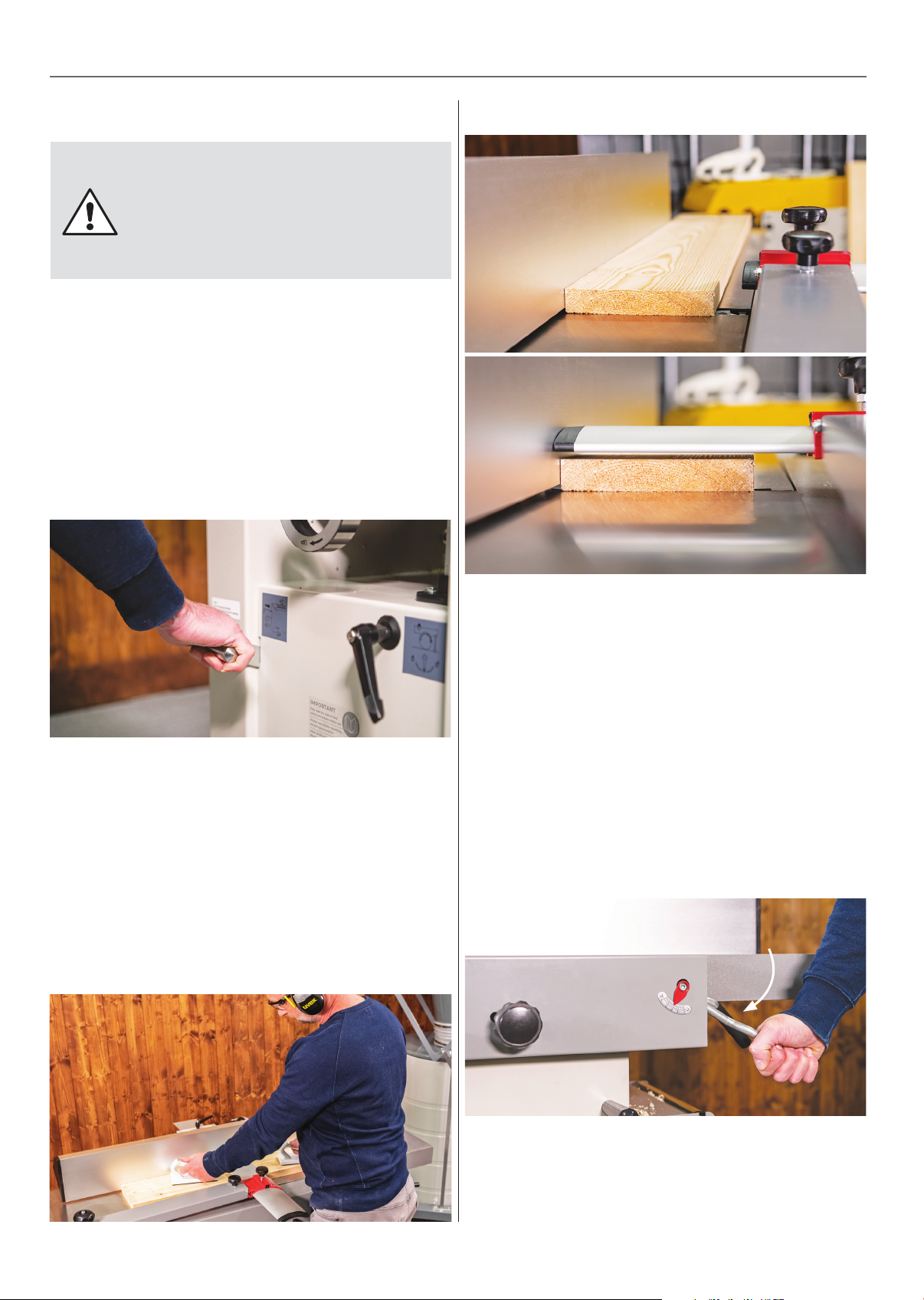
• Disengage the feed rollers(lift & pull lever out), see
fig 39.
Fig 39
Fig 41-42
• Check that there are no foreign objects e.g. old
nails, screws, small stones etc. embedded in the
material you are about to plane.
• Select the wider face. (The first planing operation).
If possible, ensure that you are not planing against
the grain and that if the timber is bowed, that the
back of the bow is uppermost (crown up). Try to
ensure that the timber is as stable on the table as
possible!, see fig 40.
Fig 40
• Set the fence, leaving sufficient exposed width
of planer blades for you to machine the largest
dimension of the workpiece, see fig 41.
• Set the bridge guard to ‘just’ clear the workpiece
allowing it to pass underneath the bridge guard but,
covering the whole of the exposed part of the cutter
block, see fig 42.
• Lower the infeed table to give the required depth
of cut/material removal, (e.g. more to work badly
distorted or very roughly finished timber, less to
‘finish’ a fine straight cut off a saw?).
Fig 43
• Press the green start button; allow the machine to
run up to speed.
10
Page 11
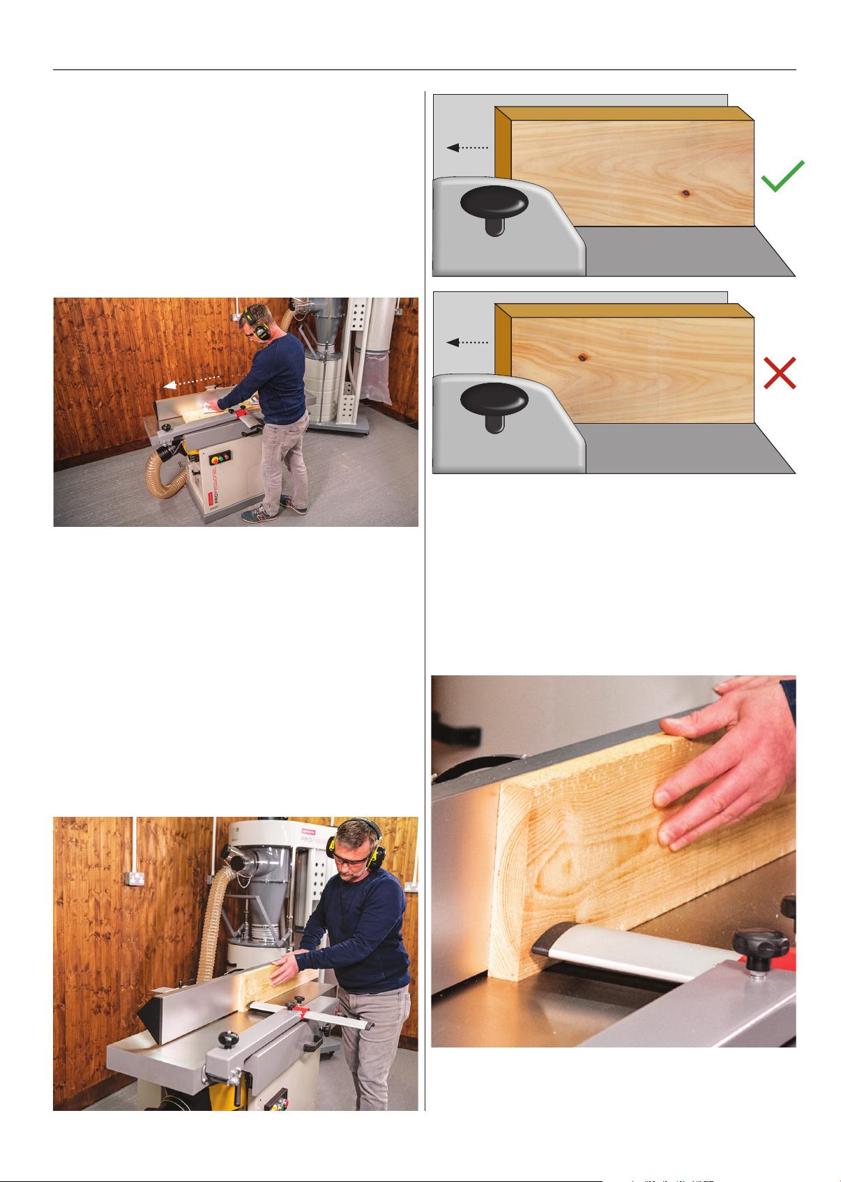
• Put the work piece onto the infeed table and
advance over the cutter block. Maintain a steady
feed speed and constant downward pressure
(usually on the outfeed table just past the cutter
block) on the timber whilst feeding, and ‘skip’ your
hands over the bridge guard when you reach it – use
push blocks where possible. Make as many passes
as required to render the timber clean, flat and
straight, see fig 44.
Fig 44
GENERAL USE OPERATION
With the Grain
Against the Grain
• Press the red stop button and let the machine run
to a stop.
Edging - The First Squaring Operation.
• Select the straightest edge or the edge that is the
most stable on the table.
• Put the selected edge down on the table also
putting the freshly planed surface against the fence.
Ensure that, if possible, you are not planing against
the grain and that if the timber is bowed, that the
back of the bow is uppermost, see fig 45-46-47.
Fig 45-46-47
• If necessary, alter the infeed table to increase or
decrease the depth of cut. It is usually possible to
remove more material when edging than when
surfacing.
• Set the fence, leaving sufficient exposed width of
planer blades for you to machine the edge of the
workpiece, see fig 48.
Fig 48
• Lower the bridge guard to cover over the
cutter block then adjust it to allow the timber
to pass through without snagging, see fig 48.
11
Page 12
GENERAL USE OPERATION
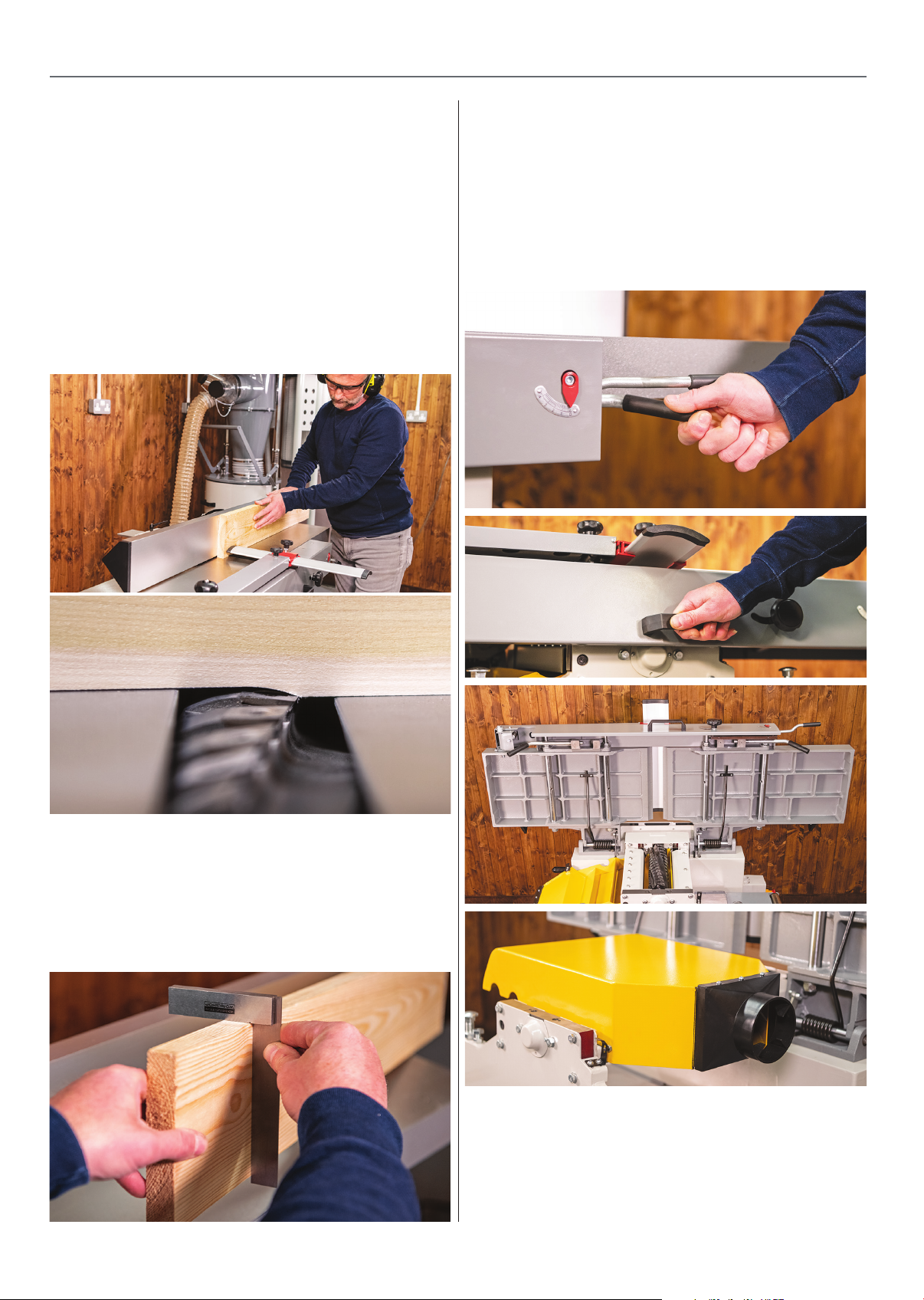
• Place the workpiece onto the infeed table and
push up against the fence.
• Press the green start button, allow the machine
to run up to speed then advance the timber over
the cutter block. Maintain a steady feed speed and
constant downward pressure and side pressure
against the fence whilst feeding; ensure that fingers
are kept high up on the top of the timber. Make as
many passes as required to render the wood flat,
straight and square, 49-50.
Fig 49-50
Thicknessing
• Release the two table lock cam handles located
at either side of the machine (twist & pull), then
using the handle lift the tables up fully to a stop,
see fig 52-53-54. Swing over into place the yellow
guard/extraction hood, see fig 55.
Fig 52-53-54-55
• When you have finished, the cut press the red
stop button and let the machine run to a stop.
• You should now have 2 straight , clean, flat
surfaces that are square to each other, see fig 51.
Fig 51
• Measure the largest/thickest section of the timber
and set the thicknesser bed to this dimension
using the depth scale on the side of the machine. It
is perfectly ok to thickness the narrow edge of the
timber, a minimum of 20mm is recommended, see
fig 56.
12
Page 13
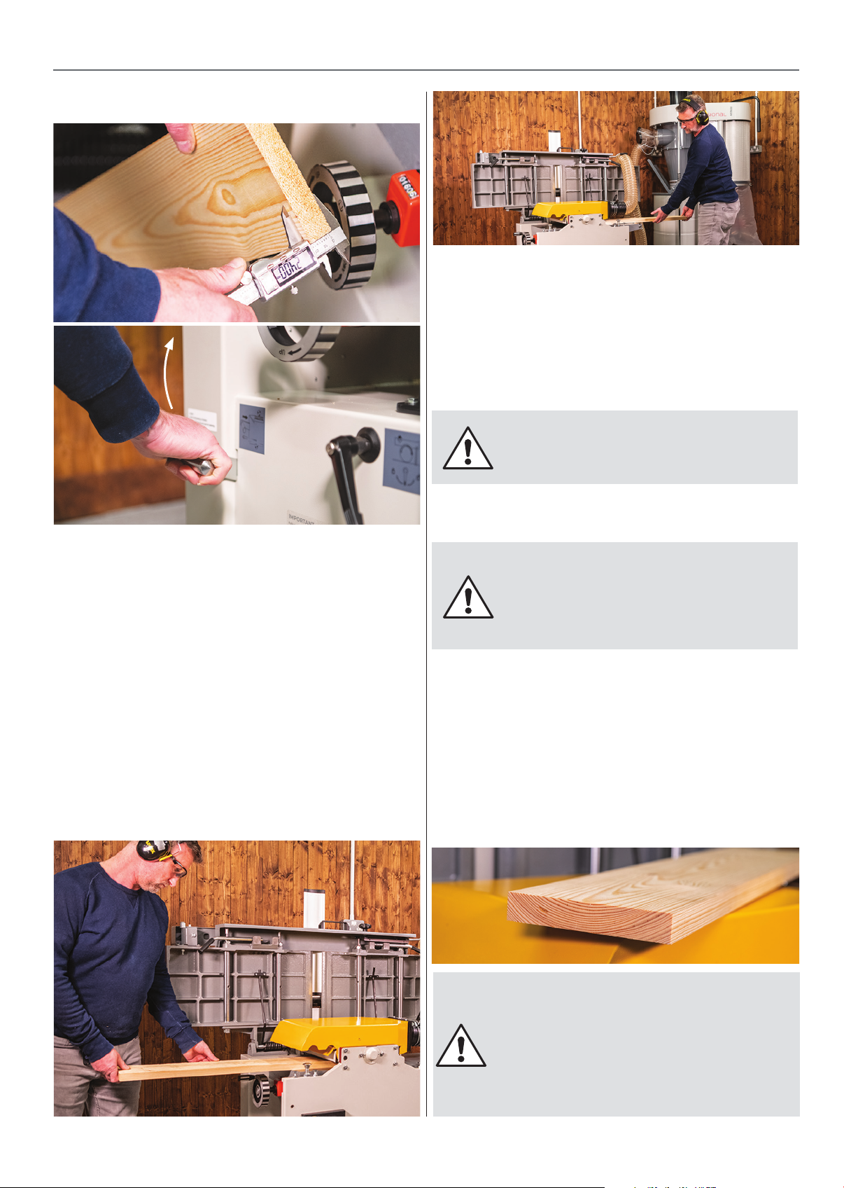
Fig 56-57
GENERAL USE OPERATION
• Move around to the ‘back’ of the machine and
support the timber to prevent it falling to the floor.
When the machining pass is complete measure
the dimension you have just cut and calculate how
much more material you have to remove to reach
the required size, see fig 59.
• Raise the thicknessing bed for the new cut.
NOTE. One complete turn of the
crank handle raises (or lowers) the
bed approximately 2mm.
• Engage the feed rollers (lift & drop lever in), see
fig 57.
• Press the green start button and allow the cutter
block to run up to full speed.
• Place the material so that the already machined
face is down, i.e. in contact with the thicknessing
bed, and you are not, if possible, cutting against the
grain.
• Push the material firmly into the machine until
the feed roller ‘picks up’ the material and moves it
through the machine, see fig 58.
Fig 58-59
Repeat the process until you reach your required
material thickness.
IMPORTANT - Wider or harder boards
will require more lighter passes to
achieve the required dimension rather
than fewer heavy passes to ensure
that the machine is not overloaded!
• REMEMBER you may want to do a ‘clean up’ pass
on your first surface as well (to remove possible
imperfections, e.g. planing ripples, small ‘dips’ that
didn’t clean perfectly during the first surfacing
phase, etc).
• You now should have clean, dimensioned, square
timber, see fig 60.
Fig 60
13
WARNING - Please ensure you
lower the thicknessing table to
a minimum of 150mm, prior to
returning the machine to planing
mode. This will prevent damage
to the dust hood or potential
misalignment of the tables.
Page 14

TROUBLESHOOTING
Planers are relatively simple machines and with all machinery, regular servicing & the correct extraction
(preventative maintenance) is essential to get the best from your machine. Below are our top five
questions answered if you find that your planer isn’t performing correctly.
Q : Why are there long raised ridges along the length of my timber after planing?
A :
Remedy: - Change/rotate blades.
Q : Why does the timber not feed through the thicknesser without stopping & stalling?
A :
Remedy: - Clean & wax the thicknesser table, clean feed rollers.
Q : Why is there a scallop cut out of the first or last few inches of the timber?
A : This is known as “Snipe”, there are 4 main reasons for snipe -
The blades may be slightly blunt or damaged, usually caused by the blades hitting a nail,
stapler, small stone or even a loose knot causing a nick in the sharp edge.
Dirty thicknessing table, usually a buildup of resin or wood chips. The feed roller may be
clogged or dirty , they may even need adjusting slightly to increase downwards pressure.
1 - The blades are set too far out of the cutter block causing snipe at the end of the timber
both in planing & thicknessing (non spiral planers only)
2 - The outfeed table is set too low in relation to the cutter block, planing only.
3 - The timber isn’t being placed flat on the thicknessing table at the start or the timber isn’t
being supported when coming out of the cut & is dropping slightly- thicknessing only.
Remedy: - Check that blades are set correctly (non spiral planers only), check that the outfeed table
is in the correct position, ensure that the timber is flat on the table both infeed & outfeed.
Q : My planer seems underpowered & slows down when cutting!
A :
Remedy: Retention drive belt, see page 16. Use sharp blades, take light cuts.
Q : My machine will not start!
A : Fuse blown, guards not in place, internal overload breaker tripped.
Remedy: Check & replace fuse, ensure that all guards are in place, check & push reset button.
Blunt blades are usually the cause,also take more lighter cut passes instead of fewer
heavy cut passes. Drive belt is loose , worn or damaged.
14
Page 15
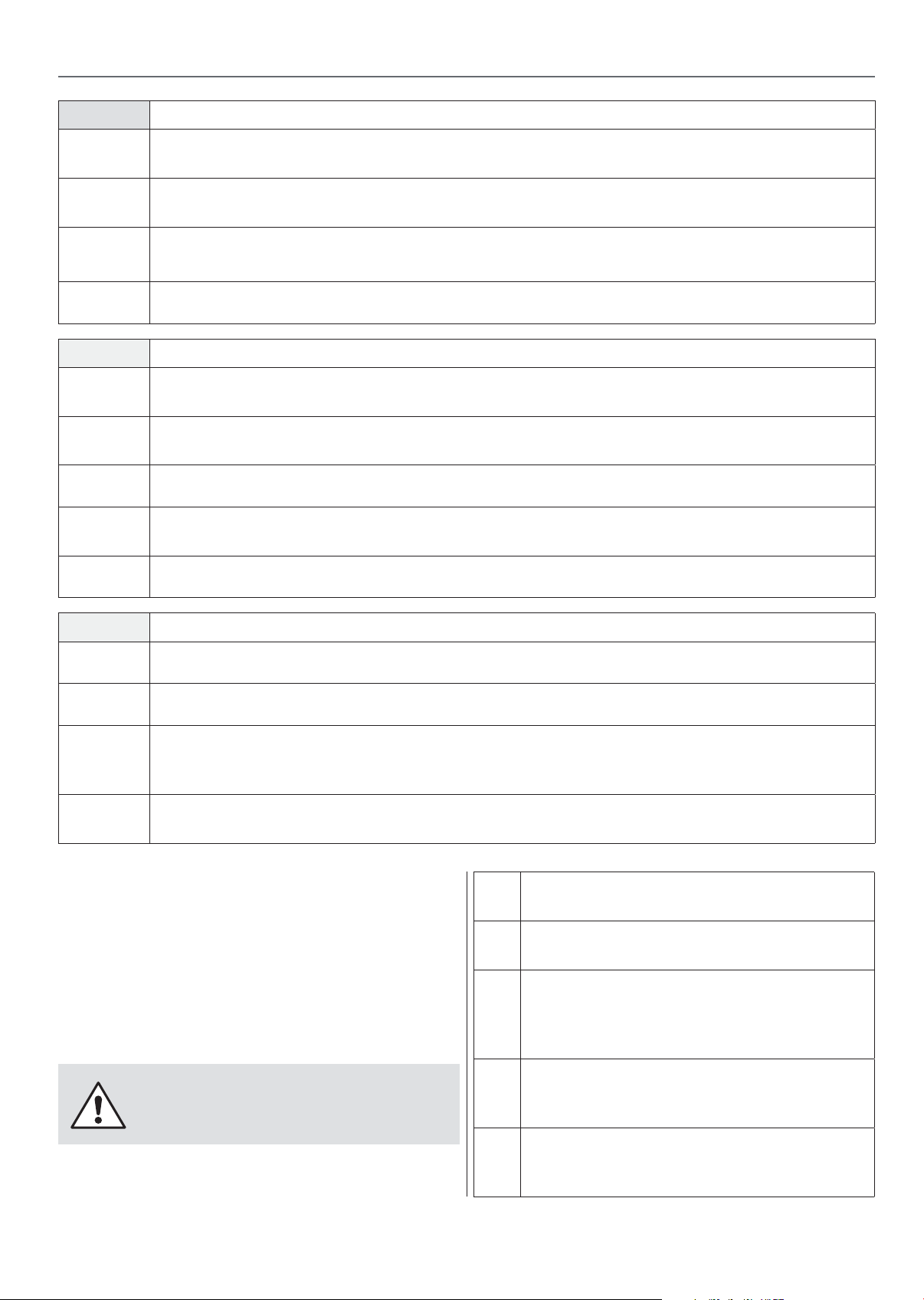
Daily -
MAINTENANCE
•
•
•
•
Weekly - Carry out the above checks, plus
•
•
•
•
•
Check that tables/beds are clean, not coated with resin etc. Apply a proprietary
cleaner/lubricating agent.
Check the cable and the plug for damage or defects. Mount the planer fence and check
it is set square.
Check the dust extraction hood and ensure there are no excessive build up of sawdust/resin,
especially in the mouth of the chip deflector and around the mouth of the extractor.
Check the blades for sharpness and damage.
Clean the machine thoroughly; remove any shavings, sawdust, chips etc,
from in, under and around the machine.
Check the cutter block for resin build up, especially behind the blade and in
the scallop of the chipbreaker/wedge.
Check that the infeed roller is free of debris & resin build up.
Lift the tables and brush out and clean any debris or build up around the
cutter block & feed rollers
Check the action of the anti-kickback fingers, again clean and lubricate as required.
Monthly - Carry out the above checks, plus
Remove the rear machine cover plate, check the condition and tension of the drive belt.
•
•
Check the auto-feed engage and disengage function.
•
•
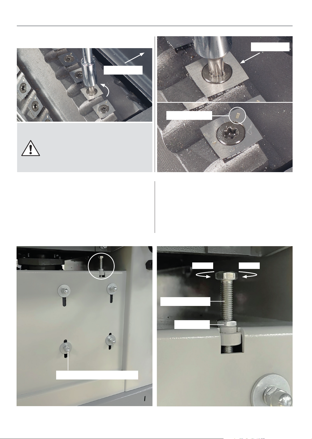
Blade Rotation/Change -
The spiral cutter block has four rows of durable
solid carbide square cutters running around its
circumference. There are 44 square cutters in total
e 260mm model and 56 cutters on the 310mm
on th
model and after many hours of use these cutters will
need rotating.
Check the condition of the drive chains, clean and apply a light coating of oil to the chains
and sprockets. Apply a light oiling to all the bearing areas, taking care not to get oil on the tyre
surfaces. Replace the rear machine cover plate.
If the table lock downs become ‘slack’ they can be adjusted by altering the height of the table
lock stud. Hold the stud firmly and loosen the lock nut.
Brush all debris from the cutter/cutters
•
that are to be rotated or changed.
Using only the tool provided undo the
•
countersink torx screw, see fig 61.
Lift & twist the carbide cutter so that the
•
fresh sharp edge faces the infeed table
direction, ensuring that there is no debris
under the cutter, see fig 62
DISCONNECT THE MACHINE FROM
THE MAINS SUPPLY BEFORE
CONTINUING!
15
Retighten the countersink torx screw &
•
repeat if numerous cutters seem blunt or
ged.
dama
NB - Each cutter has a rotation marker to
•
help you monitor which edges have been
used, see fig 62.
Continues over...
Page 16
MAINTENANCE
Fig 61-62-63
WARNING! BE VERY CAREFUL
WHEN TURNING THE CUTTERS AS
THE BLADES ARE EXTREMELY
SHARP. DO NOT OVERTIGHTEN TO
AVOID THE TORX HEAD SCREW
HEAD FROM GETTING DAMAGED!
Retention the Drive Belt
Sharp edge
Infeed table
Rotation mark
If the planer seems underpowered and slows
down when cutting then the drive belt may be
slipping and require more tension. Loosen the
four domed
thicknessing table. Loosen the tensioning bolt
locking nut and adjust the bolt at your discretion.
motor securing bolts,
below the
(NOTE: MAKE SMALL ADJUSTMENTS) Nip-up
the locking nut and re-tighten the motor domed
bolts. Start the machine and run a peice of timber
through. If adjust is still required repeat the
process until correct.
TensionSlacken
Tensioning bolt
Locking nut
Motor securing domed nuts
16
Page 17
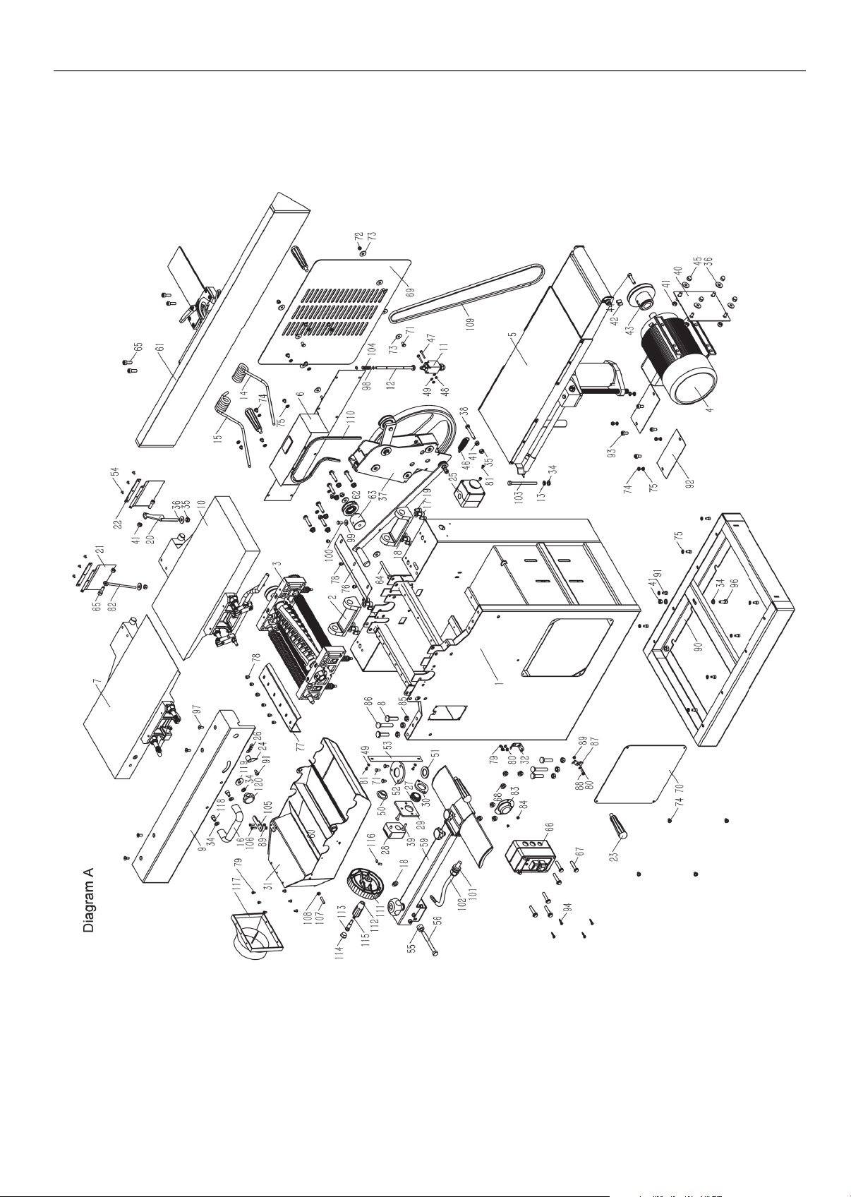
Diagram (A)
AP260SPT EXPLODED DIAGRAM PARTS LIST
17
17
Continues over...
Page 18

AP260SPT EXPLODED DIAGRAM PARTS LIST
Parts List (Diagram A)
No. Description
1 Machinery body
2 Turnover mount,planer table
3 Cutter block assembly
4 Motor
5 Thicknesser table assembly
6 Pulley cover
7 Outfeed assembly
8 Positioning bolt
9 Moveable cover
10 Infeed assembly
11 Limit switch
12 Stopping rod
13 Hex.thin nut M8
14 Supporting spring A
15 Supporting spring B
16 Hand lever
39 Cross recessed countersunk M6X25
40 Fixed board,motor
41 Hex.nut M8
42 Hex. socket set screws M8x15 with flat end
43 Motor pulley
44 Hex.socket cap head screw M8X35
45 Nut M8
46 Spring
47 Cross recessed pan head screw M4X30
48 Hex.nut M4
49 Washer 4
50 Locking axle sleeve
51 Oil-retaining bearing
52 Locking sleeve,bearing
53 Height scale,thicknesser table
54 Cross recessed countersunk M4X8
55 Spacer bush
17 Hex.socket cap head screw M10X25
18 Flat washer 10
19 Hex.socket cap head screw M6X15
20 Protective finger catch
21 Protective plate
22 Fixed strip
23 Lifting handle
24 Pointer
25 Emergency stop
26 Depth scale
27 Bearing
28 Readout
29 Fixed board,readout
30 Pressing board,bearing
31 Combined extraction hood
32 Extraction hood bracket lock
33 Hex.bolt M8X45
34 Washer 8
35 Hex.self-locking nut M8
36 Big washer 8
37 Transmission assembly
38 Hex.bolt M8X55
56 Hex.nut M10X35
57 Positioning bush
58 Cross recessed countersunk M6X16
59 Protective guard assembly
60 Hex.locking nut M10
61 Rip fence assembly
62 Tension wheel
63 Tension wheel shaft
64 Hex.bolt M8X70
65 Hex.socket cap head screw M8X25
66 Power switch
67 Hex.flange bolt M8X40
68 Hex.flange nut M12
69 Cover plate,friction wheel
70 Cover plate
71 Hex.bolt M6X12
72 Cap nut M6
73 Washer 6
74 Cross recessed pan head screw M6X8
75 Washer 6
76 Cover plate,outfeed roller
77 Cover plate,infeed roller
18
18
Page 19

AP260SPT EXPLODED DIAGRAM PARTS LIST
78 Hex.socket cap head screw M6X6
79 Cross recessed pan head screw M5X8
80 Washer 5
81 Cross recessed pan head screw M4X10
82 Stopping rod
83 Protective cover
84 Cross recessed pan head screw M5X10
85 Hex.nut M10
86 Cap-head step bolt
87 Pressing board
88 Cross recessed pan head screw M5X10
89 Hex.nut M5
90 Machine base
91 Hex.socket cap head screw M6X12
92 Protective board
93 Hex.socket cap head screw M6X15
94 Cross recessed pan head screw M5X8
95 Cross recessed pan head screw M5X8
96 Hex.socket cap head screw M8X20
97 Hex.socket countersunk screw M6X10
98 Circlips for shafts 8
100 Hex.bolt M6X16
101 Metric-bushing M20
102 Power cord
103 Hex.bolt M8X110
104 Spring
105 Pressing board
106 Cross recessed pan head screw M5X12
107 Stopping shaft,vacuum hood
108 Hex.nut M6
109 Drive belt
110 Drive chain
111 Handwheel
112 Knob
113 Screw,knob
114 End cap
115 O shape washer
116 Hex. socket set screws M6x10 with flat end
117 Dust port
118 Hex.socket cap head screw M8X12
119 Plastic gasket
120 Nut M8
99 Washer 6
19
19
Page 20
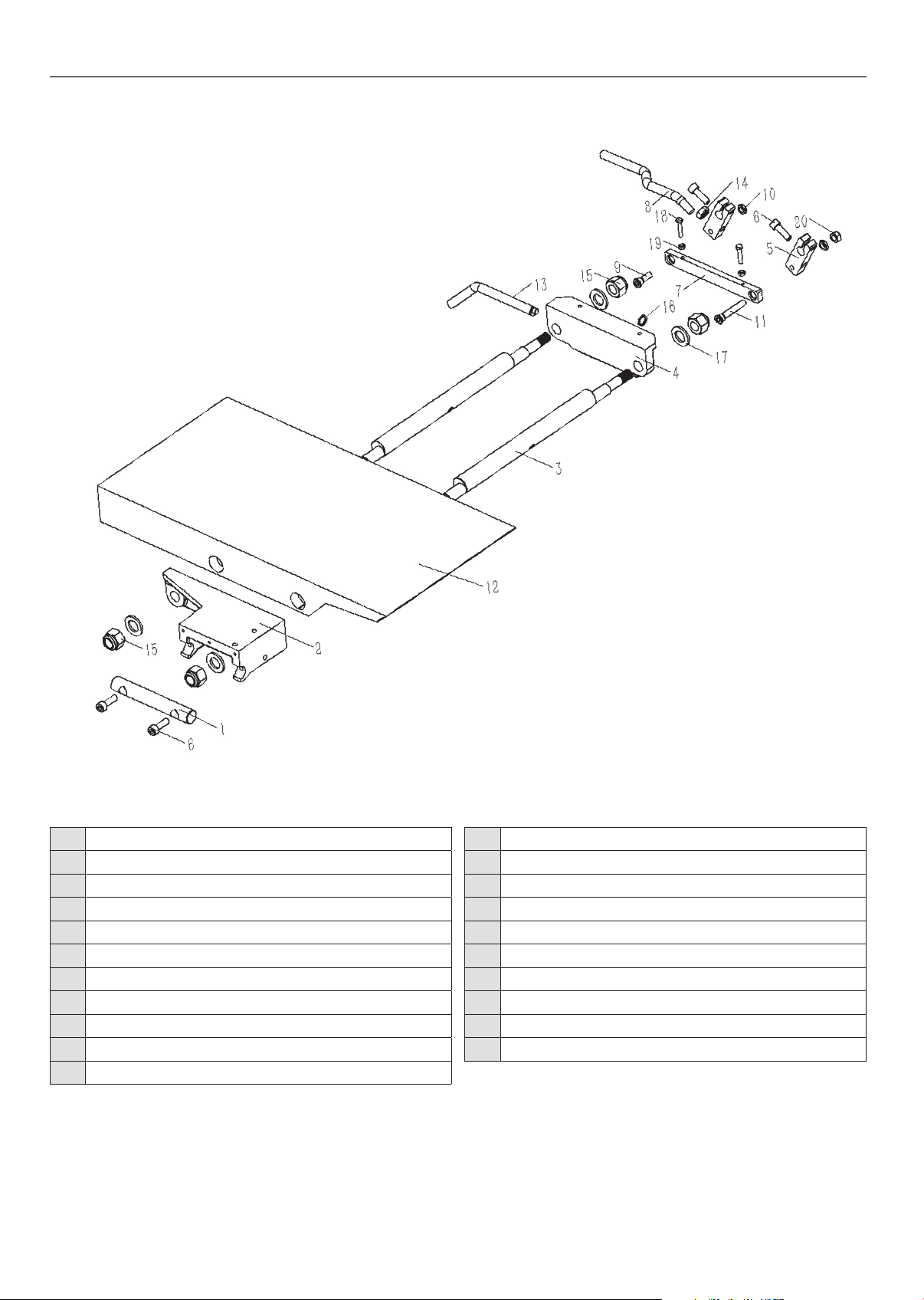
AP260SPT EXPLODED DIAGRAM PARTS LIST
Diagram (B)
Parts List (Diagram B)
No. Description
1 In-outfeed table shaft
2 Adjustable block infeed table
3 Eccentric shaft
4 Locking block,infeed table
5 Swing arm
6 Hex.socket cap head screw M8X25
7 Connection rod
8 Adjust handle, planer table
9 Step bolt
10 Thin hex.nut M8
11 Step bolt
12 Infeed table
13 Locking shaft
14 Hex.nut M10
15 Hex.locking nut M16
16 Circlips for shafts 12
17 Washer 16
18 Hex.bolt M5X25
19 Hex.nut M5
20 Hex.self-locking nut M8
20
20
Page 21
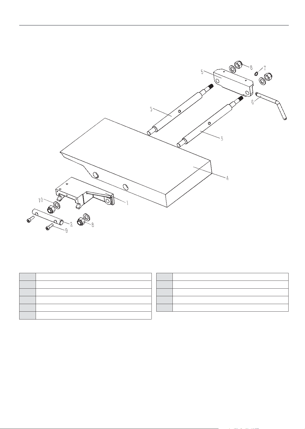
Diagram (C)
AP260SPT EXPLODED DIAGRAM PARTS LIST
Parts List (Diagram C)
No. Description
1 Adjustable block outfeed table
2 In-outfeed table shaft
3 Eccentric shaft
4 Outfeed table
5 Locking block,outfeed table
6 Table lock
7 Locking shaft
8 Hex.locking nut M16
9 Hex.socket cap head screw M8X25
10 Washer 16
21
21
Continues over...
Page 22
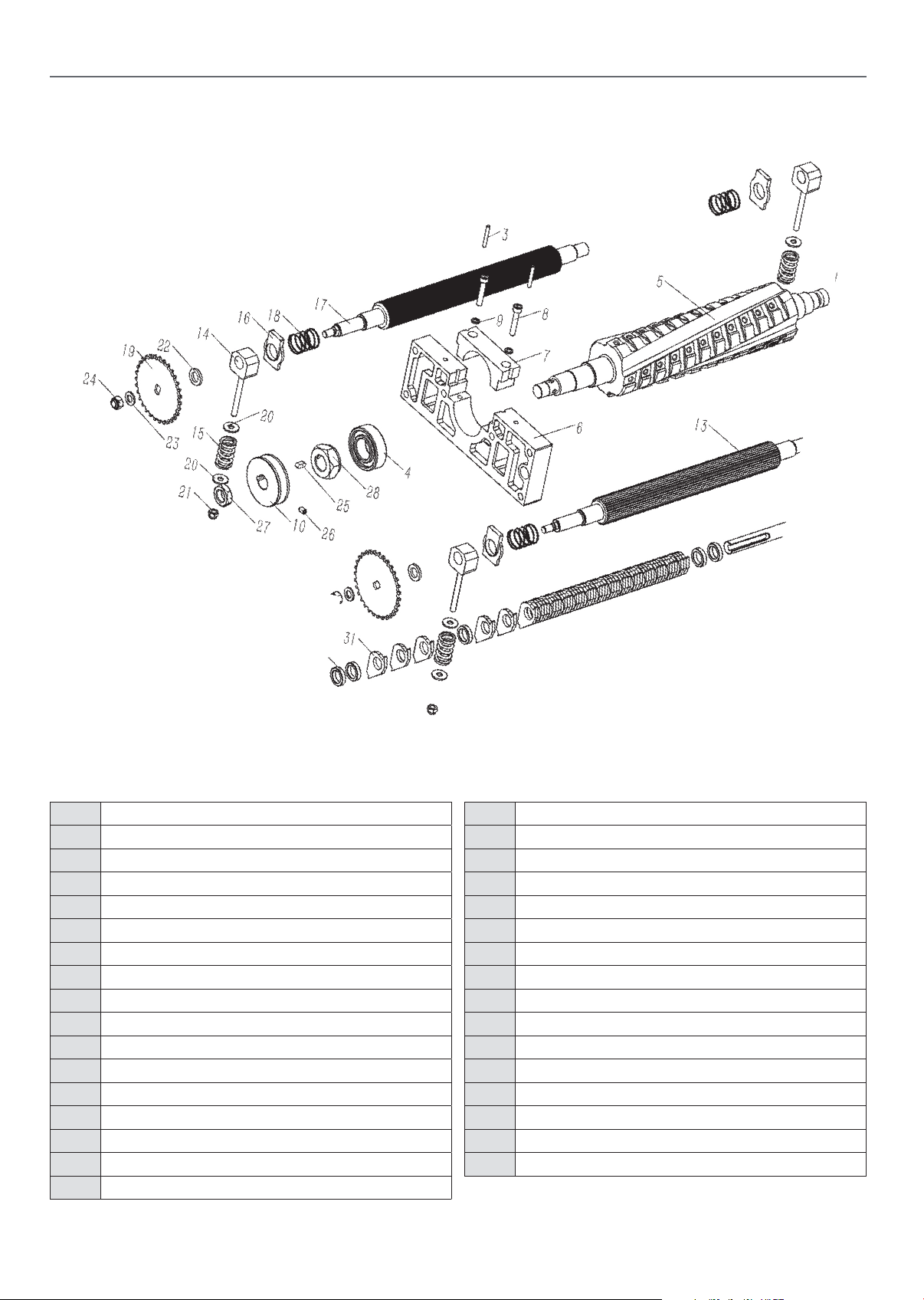
AP260SPT EXPLODED DIAGRAM PARTS LIST
Diagram (D)
Parts List (Diagram D)
No. Description
1 Cutter block bracket,front
2 Clamping block,f ront cutter block
3 Straight pin 5X25
4 Ball bearing 6205-2RZ
5 Spiral cutter block
6 Cutter block bracket,rear
7 Clamping block,rear cutter block
8 Hex.socket cap head screw M6X15
9 Spring washer 6
10 Spindle pulley
11 Special nut,cutter block
12 Washer 20
13 Infeed roller
14 Glide piece
15 Pressing spring
16 Square spacer
17 Outfeed roller
18 Spring
19 Sprocket A
20 Washer 6
21 Hex.locking nut M6
22 Sprocket spacer
23 Washer 8
24 Hex.self-locking nut M8
25 Key 5x5x10
26 Hex.socket set screw M6X10 with flat end
27 Hex.nut M16
28 Anti-loosening nut
29 Hex.socket set screw M6X8 with flat end
30 Dust hood shaft
31 Recoil lock
32 Collar
22
22
Page 23
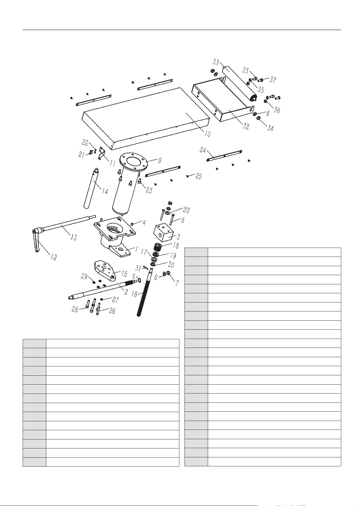
Diagram (E)
AP260SPT EXPLODED DIAGRAM PARTS LIST
Parts List (Diagram E)
No. Description
1 Fixed guide rail
2 Clamp lever,assembly
3 Raise gear seat
4 Hex.socket set screw M8X12 with flat end
5 Circlips for shafts 18
6 Washer 10
7 Hex.locking M10
8 Hex.bolt M6X60
9 Raise guide rail
10 Thicknesser table
11 Height pointer
12 Ratchet lever
13 Clamp rod
14 Special guide
15 Screw guide
16 Raise guide rod
17 Spacer
18 Raise gear
19 Thrust bearing 51102
20 Thrust roller pin washer assembly AXK1024
21 Cross recessed pan head screw M4X12
22 Washer 14
23 Hex.socket cap head screw M8X16
24 Edge-plate
25 Cross recessed countersunk screw M4X8
26 Hex.socket cap head screw M6X40
27 Hex.nut M6
28 Hex.socket cap head screw M8X35
29 Spring washer 8
30 Spacer
31 Straight pin 5x10
32 Extension table,thicknesser table
33 Roller
34 Hex.nut M10
35 Washer 8
36 Hex.nut M8
37 Hex.bolt M8X20
23
23
Continues over...
Page 24
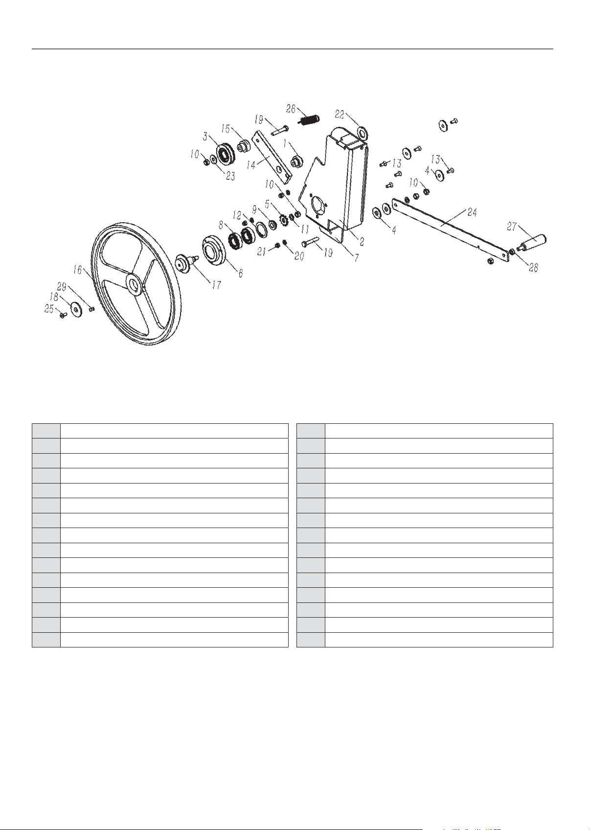
AP260SPT EXPLODED DIAGRAM PARTS LIST
Diagram (F)
Parts List (Diagram F)
No. Description
1 Positioning bush
2 Guide,friction pulley
3 Tension pulley
4 Plastic washer
5 Sprocket B
6 Spacer lock
7 Guide,friction pulley
8 Ball bearing 6004-2RZ
9 Sprocket washer
10 Hex.self-locking nut M8
11 Washer 8
12 Circlips for holes 42
13 Cross recessed countersunk M6X16
14 Tension plate
15 Collar
16 Sprocket A
17 Shaft
18 Shaft gland
19 Hex.bolt M8X45
20 Washer 6
21 Hex.locking nut M6
22 Washer 20
23 Big washer 8
24 Lever friction pulley
25 Hex.socket countersunk M6X16
26 Pull spring
27 Handle,lever
28 Hex.nut M8
29 Key 8x7x7
24
24
Page 25
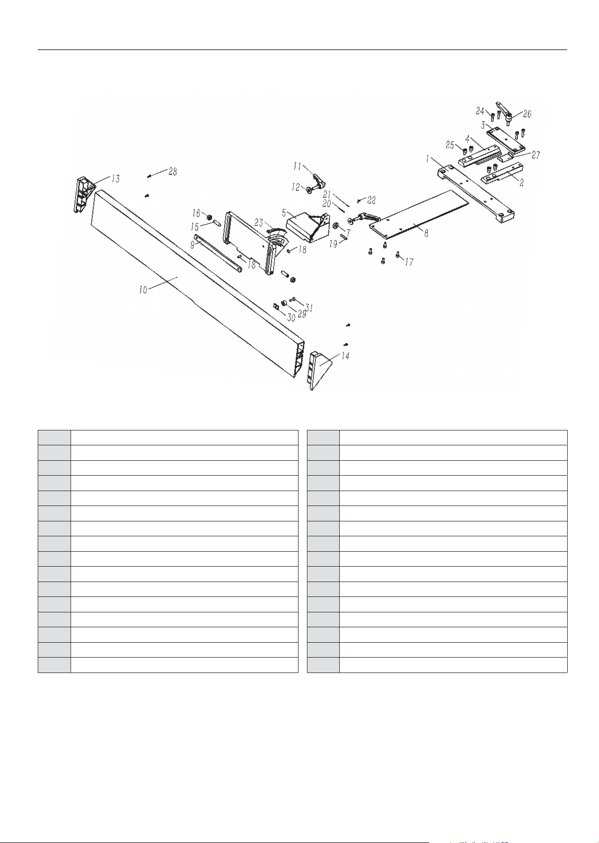
Diagram (G)
AP260SPT EXPLODED DIAGRAM PARTS LIST
Parts List (Diagram G)
No. Description
1 Guide bracket
2 Right guide block
3 Wedge-cover
4 Left guide block
5 Fence segment
6 Fence carrier
7 Washer
8 Arbor guard plate
9 Bolt guide
10 Rip fence
11 Adjusting handle M8X28
12 Washer 8
13 Right end cover,rip fence
14 Left end cover,rip fence
15 Hex.socket set screw M10X35 with taper end
16 Hex.nut M10
17 Hex.socket cap head screw M6X16
18 Hex.socket set screw M6X15 with flat end
19 Split straight pin 6x30
20 Pointer
21 Washer4
22 Cross recessed pan head screw M4x8
23 Angle scale
24 Hex.socket cap head screw M6X25
25 Hex.socket cap head screw M8X12
26 Adjusting handle M8X20
27 Pad plate
28 Cross recessed pan head tapping screw ST3.5X12
29 Spacer
30 Square nut
31 Cross recessed countersunk M6X20
25
25
Continues over...
Page 26
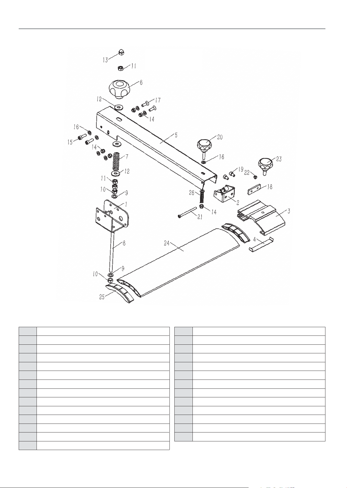
AP260SPT EXPLODED DIAGRAM PARTS LIST
Diagram (H)
Parts List (Diagram G)
No. Description
1 Swivel base
2 Locking support
3 Joint,bridge guard
4 Pad plate
5 Fence carrier
6 Round knob
7 Spring
8 Screw rod
9 Washer 8
10 Hex.self-locking nut M8
11 Hex.nut M8
12 Big washer 8
13 Cap nut M8
14 Hex.locking M6
15 Hex.socket cap head screw M6X20
16 Washer 6
17 Cross recessed countersunk M6X20
18 Bolt guide
19 Hex.socket cap head screw M6X20
20 Round knob M6
21 Cross recessed pan head screw M5X65
22 Hex.locking M5
23 Round knob M8
24 Protective guard
25 End cap,protective guard
26 Spring
26
26
AP260SPT Wiring Diagram go to page 37...
Page 27
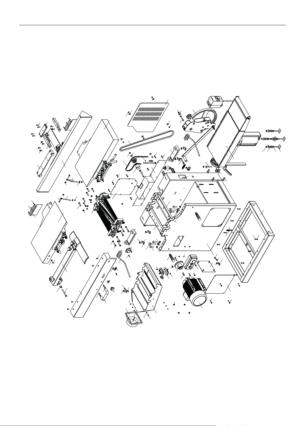
Diagram (A)
AP310SPT EXPLODED DIAGRAM PARTS LIST
39
51
23
18
38
52
37
19
50
70
71
72
24
20
15
21
25
69
73
33
26
65
79
41
16
42
53
95
90
58
57
56
59
87
112
1
30
67
8
65
113
43
78
82
100
108
68
12
67
61
99
55
35
60
67
40
74
96
13
98
3
109
76
59
92
10
25
96
36
68
41
93
67
31
44
107
84
102
103
97
59
46
105
83
104
106
45
29
65
9
13
48
54
114
77
49
76
47
28
6
115
80
17
68
4
86
5
85
75
7
14
2
42
81
34
94
66
37
22
63
64
101
65
11
32
88
62
76
27
Continues over...
Continues over...
Page 28

AP310SPT EXPLODED DIAGRAM PARTS LIST
Parts List (Diagram A)
No. Description
1 Machine body
2 Spiral cutter block assembly
3 Cover plate,outfeed roller
4 Cover plate,infeed roller
5 Positioning bolt
6 Locking bolt
7 Combined vacuum hood
8 Motor
9 Tension wheel shaft
10 Motor pulley
11 Transmission assembly
12 Thicknesser table assembly
13 Turnover mount,planer table
14 Infeed table assembly
15 Outfeed table assembly
16 Moveable cover
39 Fixed strip
40 Lifting handle
41 Hex.flange bolt M8X40
42 Hex.nut M8
43 Stoppong plate,dust port
44 Depth scale
45 Cross recessed pan head screw M4X6
46 Washer 4
47 Hex.bolt M10X25
48 Washer 10
49 Hex. socket set screws M8x12 with flat point
50 Pressing board
51 Cross recessed countersunk M4X8
52 Hex.socket cap head screw M6X25
53 Switch box
54 Tension wheel
55 Fixed bolt
17 Pulley cover
18 Guide bracket
19 Left guide block
20 Right guide block
21 Rip fence assembly
22 Hand lever
23 Protective plate
24 Hex.socket cap head screw M8X25
25 Hex.nut M8
26 Protective finger catch
27 Limit switch
28 Stopping rod
29 Protective cover
30 Fixed board,motor
31 Supporting spring B
32 Supporting spring A
33 Stopping rod
56 Adjustable nut
57 Washers with ball face
58 Big washer 8
59 Hex.self-locking nut M8
60 Locking axle sleeve
61 Machine base
62 Pull spring
63 Hex.bolt M8X55
64 Hex.bolt M8X45
65 Big washer 8
66 Washer 8
67 Washer 6
68 Cross recessed pan head screw M6X8
69 Protective guard assembly
70 Positioning bush
71 Cross recessed countersunk M6X16
72 Spacer bush
34 Pointer
35 Cover plate,friction wheel
36 Cover plate
37 Hex.socket cap head screw M8X12
38 Hex.socket cap head screw M8X20
73 Hex.bolt M10X100
74 Scale, body
75 Hex.bolt M6X16
76 Hex.nut M6
77 Hex.bolt M8X70
28
Page 29

AP310SPT EXPLODED DIAGRAM PARTS LIST
78 Big washer 6
79 Hex.locking nut M6
80 Stopping shaft,vacuum hood
81 Hex.socket countersunk screw M6X16
82 Cap nut M8
83 Drive belt
84 Drive chain
85 Hex.nut M10
86 Hex.nut M16
87 Hex. socket set screws M8x50 with flat end
88 Metric-bushing M20
89 Power cord
90 Motor start
91 Cross recessed pan head screw M4X10
92 Hex.socket cap head screw M8X35
93 Nut.M8
94 Plastic gasket
97 Cap nut M6
98 Hex.bolt M6X12
99 Hex.socket cap head screw M6X12
100 Hex.socket cap head screw M6X20
101 Key 8x7x32
102 Pressing board
103 Cross recessed pan head screw M5X12
104 Hex.nut M5
105 Dust port
106 Crossrecessed pan head tapping screws ST 4.2X10
107 Hex.socket cap head screw M6X16
108 Cover plate
109 Hex. socket set screws M8x50 with flat point
110 Cross recessed pan head screw M4X30
111 Hex.nut M4
112 Cross recessed pan head screw M5X10
113 Wasjer 5
95 Cross recessed pan head screw M6X30
96 Big washer 6
114 Circlips for shafts 8
115 Spring
29
Page 30
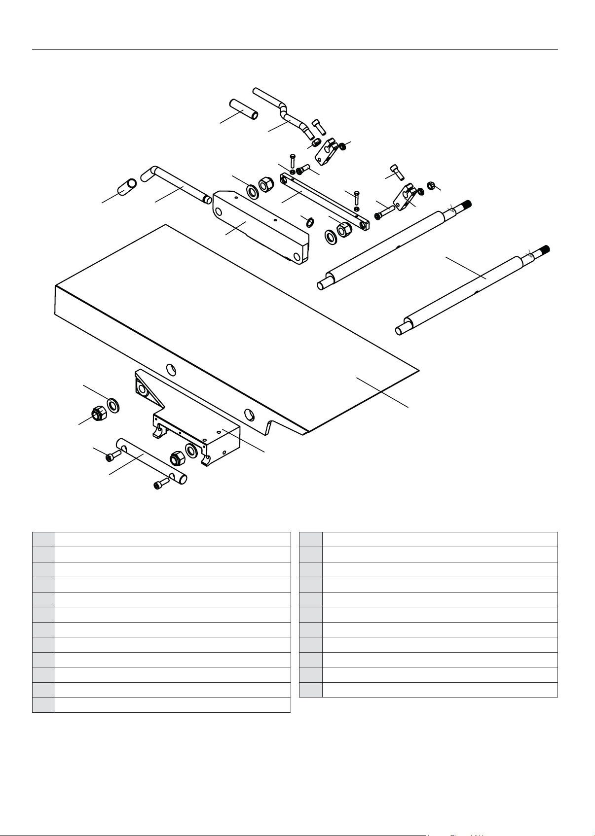
AP310SPT EXPLODED DIAGRAM PARTS LIST
Diagram (B)
19
21
13
22
19
4
8
17
16
10
12
6
20
5
14
9
7
15
18
3
11
18
6
1
Parts List (Diagram B)
No. Description
1 In-outfeed table shaft
2 Adjustable block, infeed table
3 Eccentric shaft
4 Locking block,infeed table
5 Swing arm
6 Hex.socket cap head screw M8X25
7 Connection rod
8 Adjust handle, planer table
9 Step bolt
10 Thin hex.nut M8
11 Infeed table
2
12 Step bolt
13 Eccentric handle
14 Hex.nut M10
15 Circlips for shafts 15
16 Hex.bolt M5X25
17 Hex.nut M5
18 Hex.locking nut M16
19 Washer 16
20 Hex.self-locking nut M8
21 Handle sleeve
22 Handle sleeve
30
Page 31
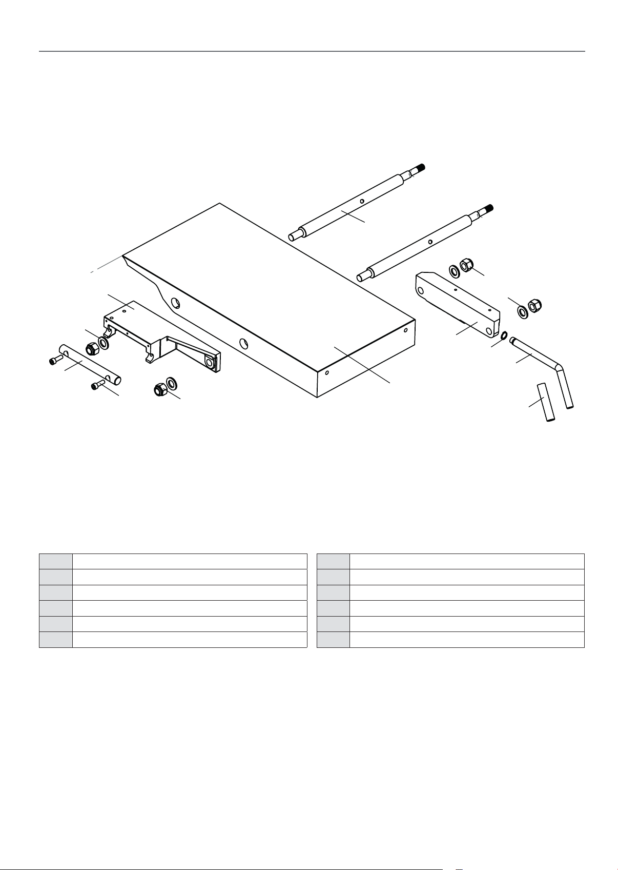
Diagram (C)
AP310SPT EXPLODED DIAGRAM PARTS LIST
3
7
1
8
2
6
Parts List (Diagram C)
No. Description
1 Adjustable block, outfeed table
2 In-outfeed table shaft
3 Eccentric shaft
4 Outfeed table
5 Locking block,outfeed table
8
5
10
9
4
7
6 Hex.socket cap head screw M8X25
7 Hex.locking nut M16
8 Washer 16
9 Table lock
10 Circlips for shafts 15
11 Handle sleeve
11
31
Continues over...
Page 32
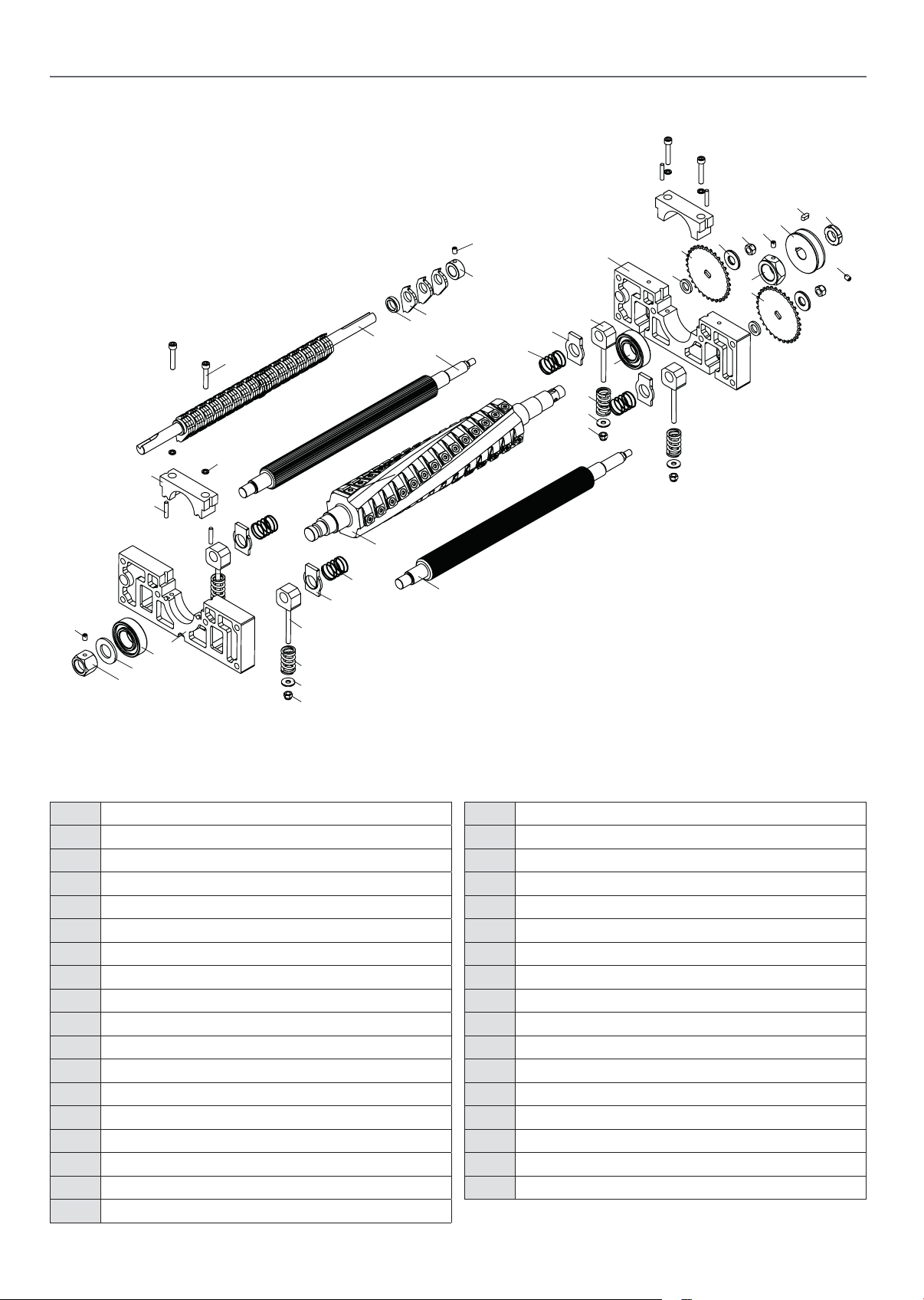
AP310SPT EXPLODED DIAGRAM PARTS LIST
Diagram (D)
28
20
18
19
17
3
16
12
14
34
10
9
28
27
32
1
11
5
13
30
31
26
29
22
26
33
8
4
28
24
7
5
25
6
Parts List (Diagram D)
No. Description
1 Cutter block bracket,rear
2 Clamping block,rear cutter block
3 Hex.socket cap head screw M6X35
4 Roll pin 5x25
5 Ball bearing 6205-2RZ
6 Spring washer 6
7 Cutter block bracket,front
8 Clamping block,front cutter block
9 Spindle pulley
10 Anti-loosening nut
11 Glide piece
12 Square spacer
13 Pressing spring
14 Spring
15 Outfeed roller
16 Infeed roller
17 Dust hood shaft
21
14
12
11
13
30
31
15
18 Recoil lock
19 Collar
20 Spiral cutter block assembly
21 Anti-loosening nut
22 Cutter blade
23 Nut,cutter block
24 Washer 20
25 Sprocket A
26 Hex.self-locking nut M8
27 Hex.socket set screw M6X8 with flat end
28 Sprocket spacer
29 Big washer 6
30 Hex.locking nut M6
31 Sprocket washer
32 Hex.socket set screw M6X10 with taper end
33 Key 5x5x12
34 Collar
32
Page 33
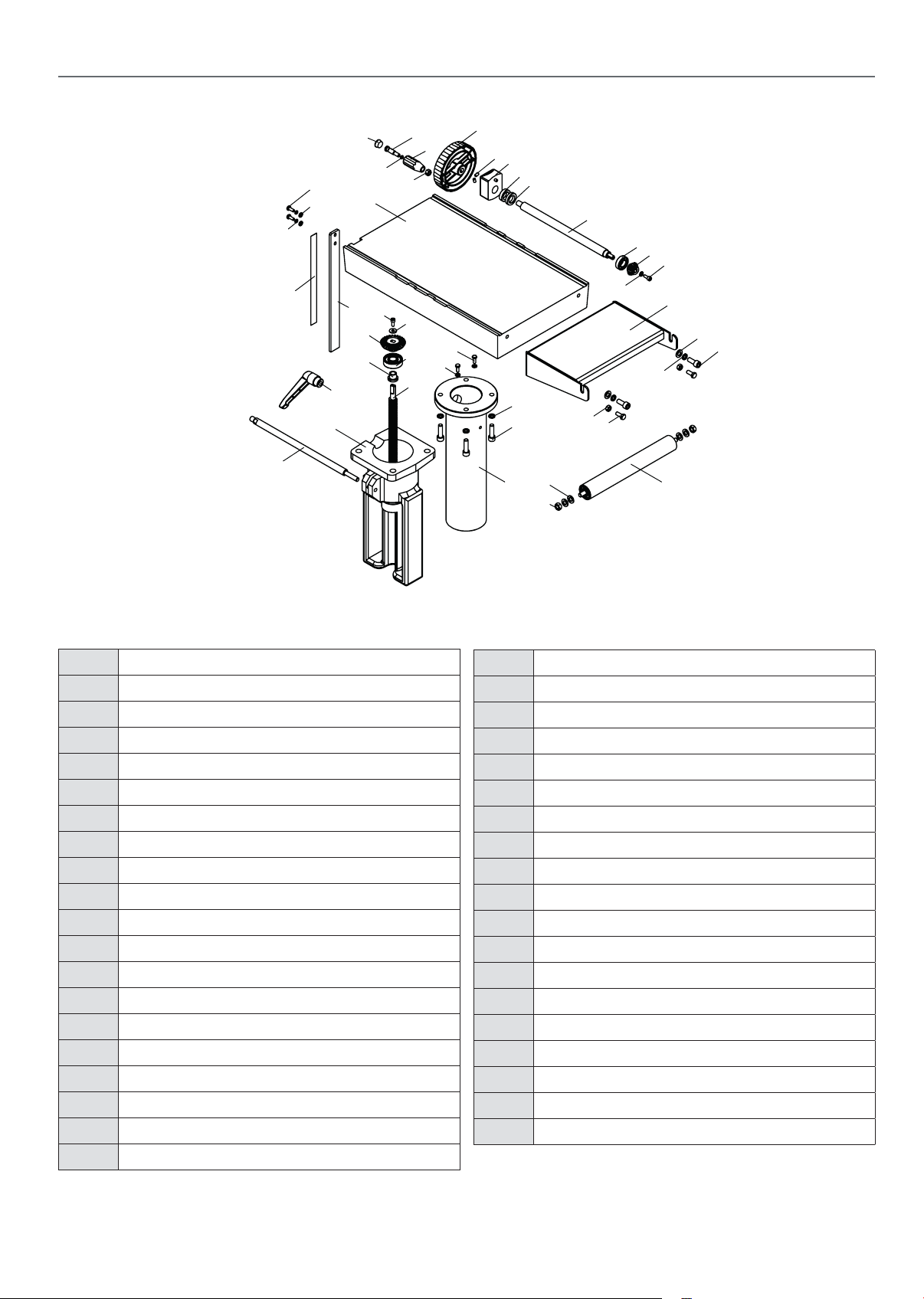
Diagram (E)
18
4
1
15
27
9
29
5
22
21
23
31
30
7
11
3
8
21
22
14
13
19
20
19
24
14
25
26
31
22
10
2
6
12
16
28
37
32
33
38
36
3435
17
Diagram E
AP310SPT EXPLODED DIAGRAM PARTS LIST
Parts List (Diagram E)
No. Description
1 Fixed guide rail
2 Ball bearing 6003-2LS
3 Bearing seat
4 Raise guide rail
5 Thicknesser table
6 Raise drive rod
7 Cone gear A
8 Raise guide rod
9 Scale rule
10 Cone gear B
11 Ball bearing 6303-2RZ
12 Collar stop
13 Hex.socket cap head screw M10X35
14 Spring washer 10
15 Clamp rod
16 Collar stop
17 Extension thicknesser table assembly
18 Roller
19 Washer 10
20 Hex.nut M10
21 Hex.bolt M6X16
22 Washer 6
23 Spring washer 6
24 Hex.socket cap head screw M10X25
25 Hex.nut M8
26 Hex.bolt M8X20
27 Ratchet lever
28 Readout
29 Height scale,thicknesser table
30 Big washer 6
31 Hex.socket cap head screw M6X16
32 Handwheel
33 Knob
34 Knob screw
35 End cap
36 O shape washer
37 Hex. socket set screws M6x10 with flat end
38 Hex.nut M8
33
Continues over...
Page 34
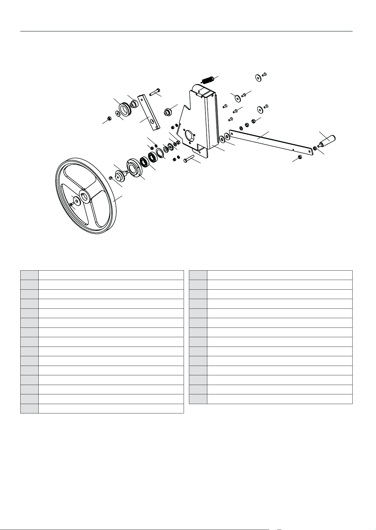
AP310SPT EXPLODED DIAGRAM PARTS LIST
Diagram (F)
25
17 18
20
Parts List (Diagram F)
11
16
3
21
4
1
28
15
11
27
26
7
10
12
13
5
2
21
14
14
11
22
23
4
24
11
9
6
19
No. Description
1 Positioning bush
2 Guide,friction pulley
3 Tension pulley
4 Plastic washer
5 Sprocket B
6 Spacer lock
7 Shaft
8 Guide,friction pulley
9 Guide,friction pulley
10 Ball bearing 6004-2RZ
11 Sprocket washer
12 Washer 8
13 Circlips for holes 42
14 Cross recessed countersunk M6X16
15 Tension plate
16 Collar
17 Shaft gland
18 Sprocket A
19 Key 8x7x7
20 Hex.socket countersunk M6X16
21 Hex.bolt M8X45
22 Lever,friction pulley
23 Handle,lever
24 Hex.nut M8
25 Pull spring
26 Hex.locking nut M6
27 Washer 6
28 Big washer 8
34
Page 35
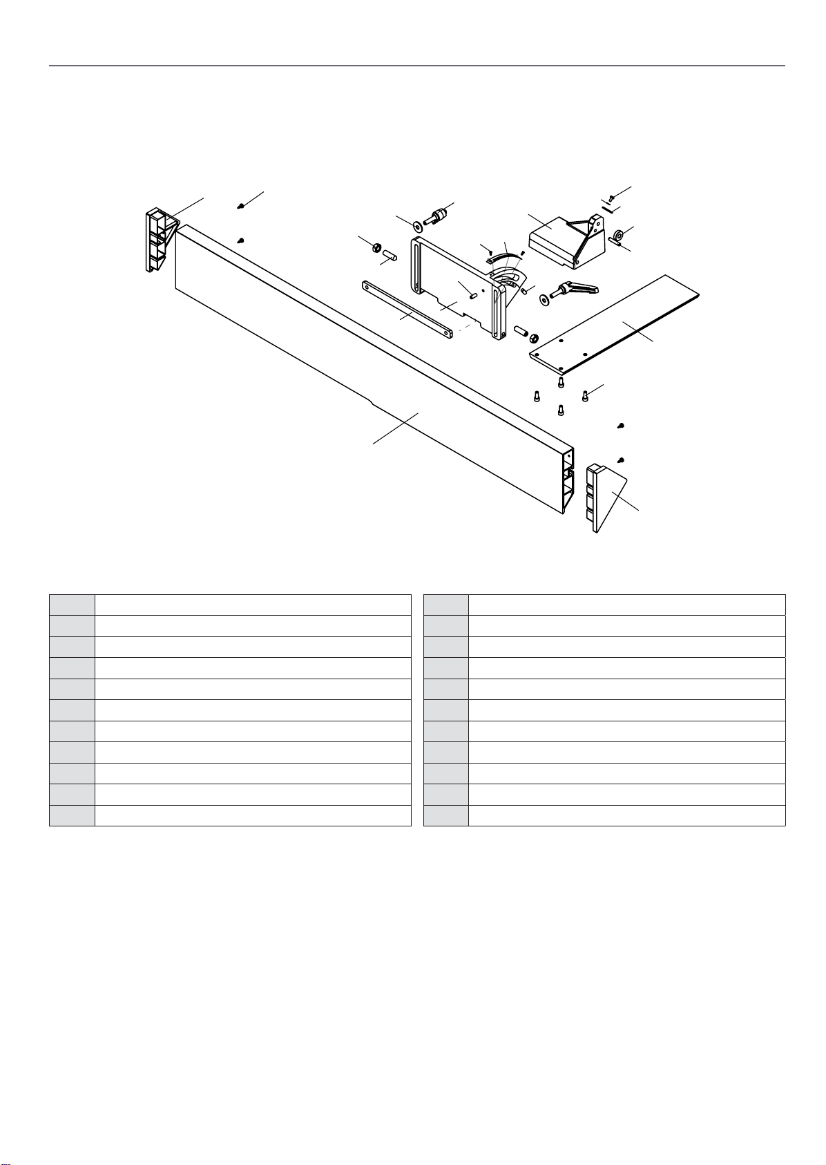
Diagram (G)
Diagram G
AP310SPT EXPLODED DIAGRAM / PARTS LIST
Parts List (Diagram G)
9
20
12
7
8
21
1
19
17
18
16
3
15
11
14
2
5
14
4
13
6
10
No. Description
1 Fence segment
2 Fence carrier
3 Washer
4 Arbor guard plate
5 Bolt guide
6 Rip fence
7 Adjusting handle M8X28
8 Washer 8
9 Right end cover,rip fence
10 Left end cover,rip fence
11 Hex.socket set screw M10X35 with taper end
12 Hex.nut M10
13 Hex.socket cap head screw M6X16
14 Hex.socket set screw M6X15 with flat end
15 Split straight pin 6x30
16 Pointer
17 Washer 4
18 Cross recessed pan head screw M4x8
19 Angle scale
20 Cross recessed pan head tapping screw ST3.5X12
21 Rivet 3x6
35
Continues over...
Page 36
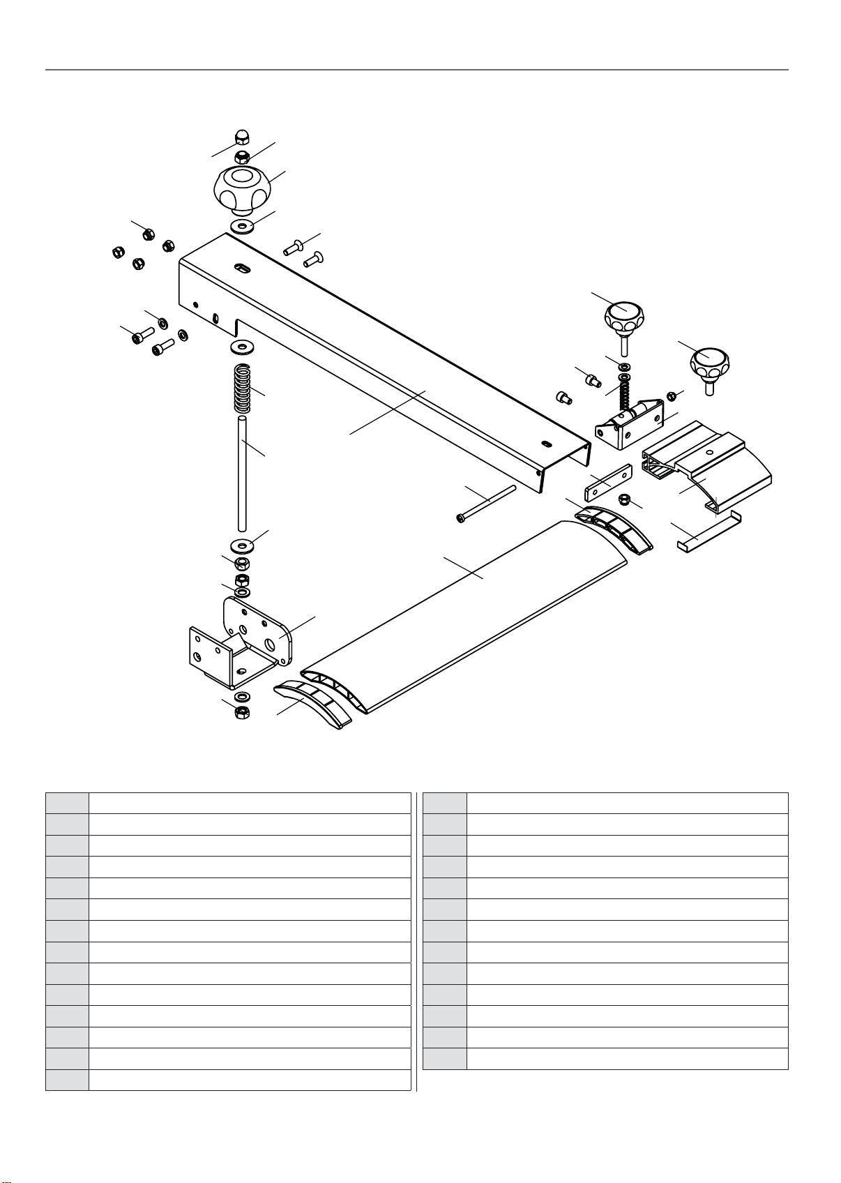
AP310SPT EXPLODED DIAGRAM PARTS LIST
2
1
15
5
16
12
14
13
3
25
4
10
26
7
11
17
24
20
22
6
8
9
7
23
18
22
21
19
20
5
8
Diagram (H)
Parts List (Diagram H)
No. Description
1 Swivel base
2 Fence carrier
3 Joint,bridge guard
4 Locking support
5 End cap,protective guard
6 Cross recessed countersunk M6X20
7 Washer 6
8 Hex.locking nut M6
9 Hex.socket cap head screw M6X20
10 Hex.locking nut M5
11 Spring
12 Round knob M6
13 Pad plate
14 Round knob M8
15 Protective guard
16 Cross recessed pan head screw M5X8
17 Round knob
18 Screw rod
19 Washer 8
20 Hex.self-locking nut M8
21 Hex.nut M8
22 Big washer 8
23 Spring
24 Cap nut M8
25 Bolt guide
26 Hex.socket cap head screw M6X10
36
Page 37
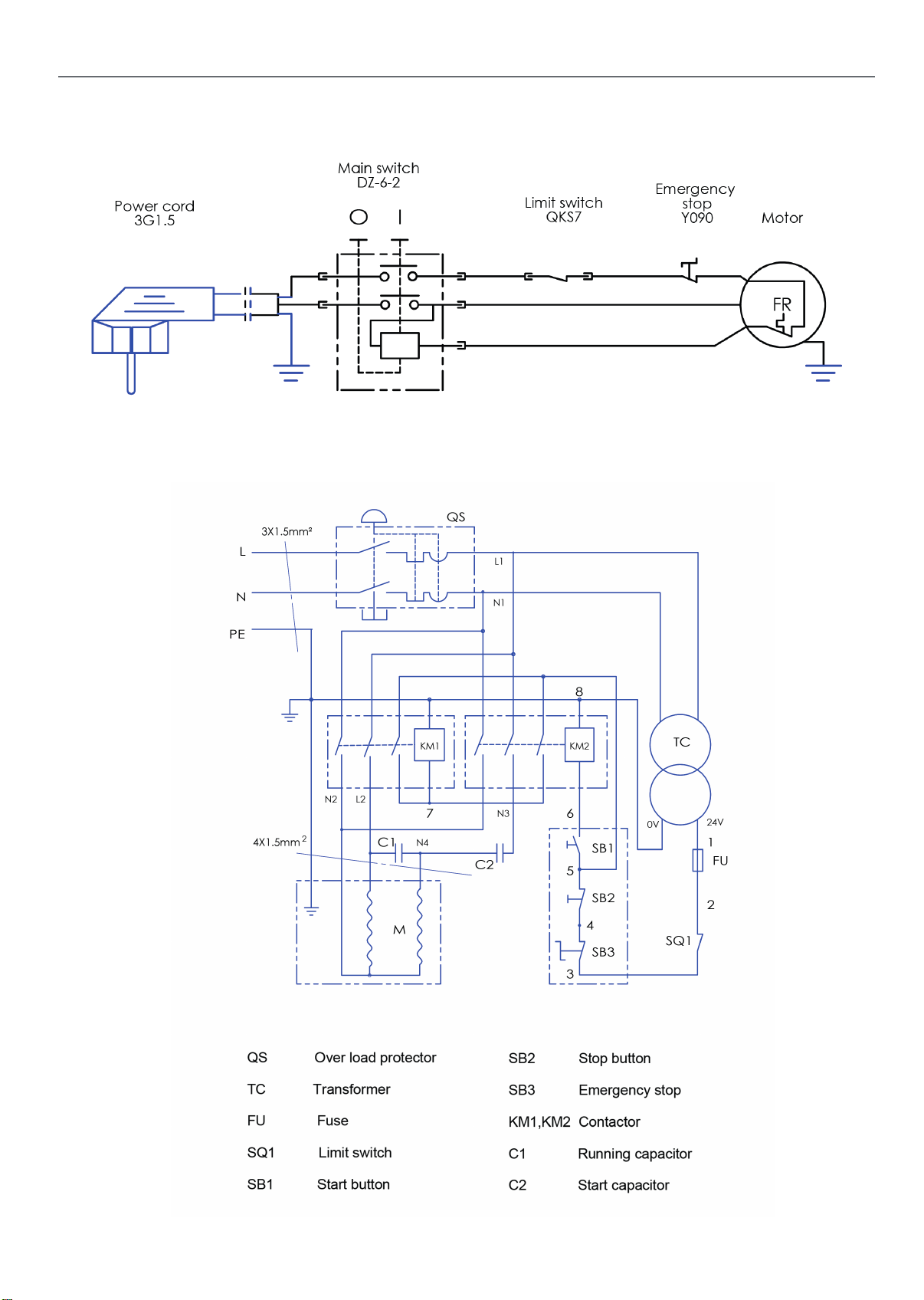
Model: AP260SPT
Model: AP310SPT
WIRING DIAGRAM
37
Page 38

38
Page 39
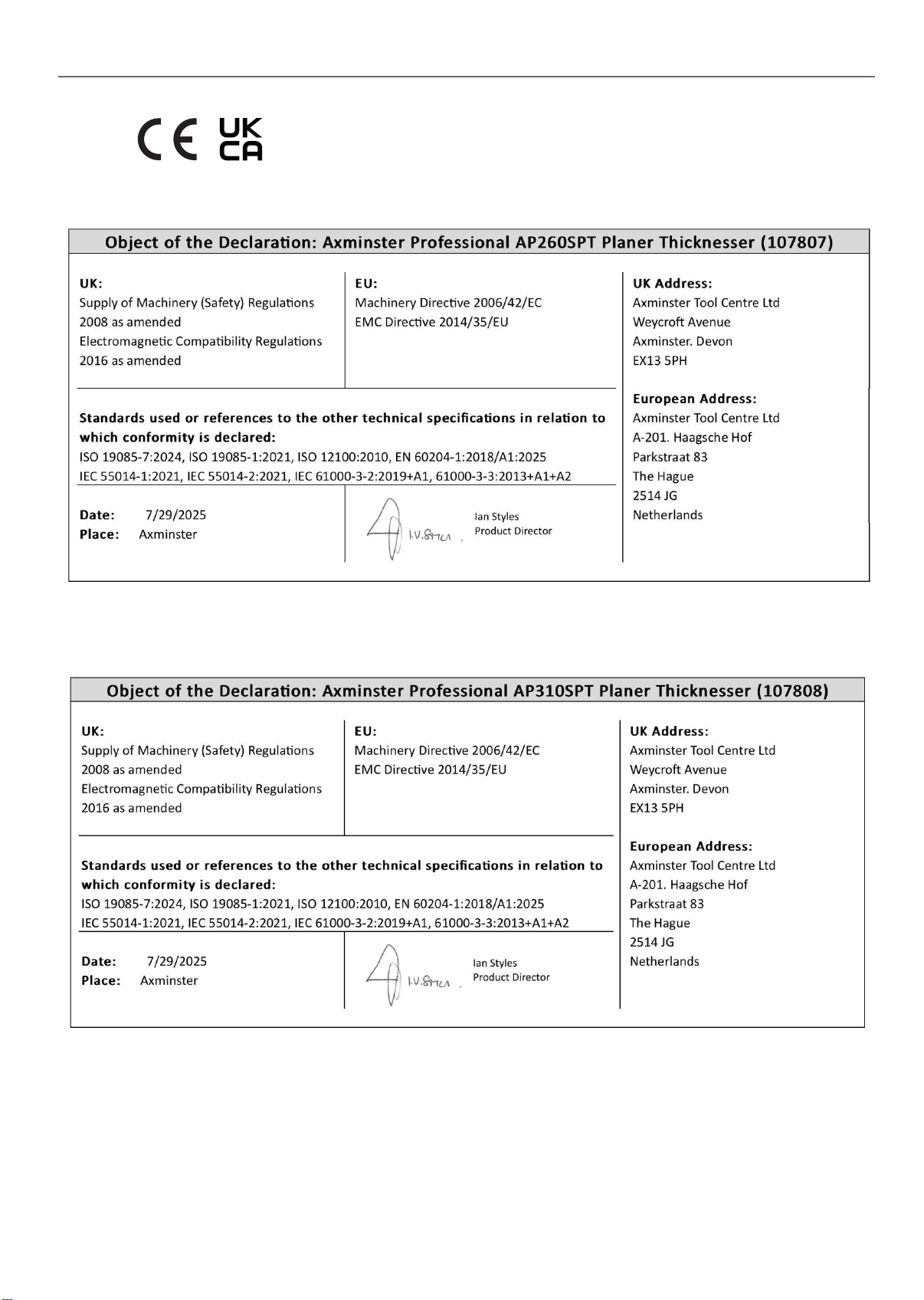
DECLARATION OF CONFORMITY
39
Page 40

The packaging is suitable for recycling.
Please dispose of it in a responsible manner.
EU Countries Only
Do not dispose of electric tools together with household waste material.
By law they must be collected and recycled separately.
Axminster Tools, Axminster Devon EX13 5PH
axminstertools.com
 Loading...