

Page 1
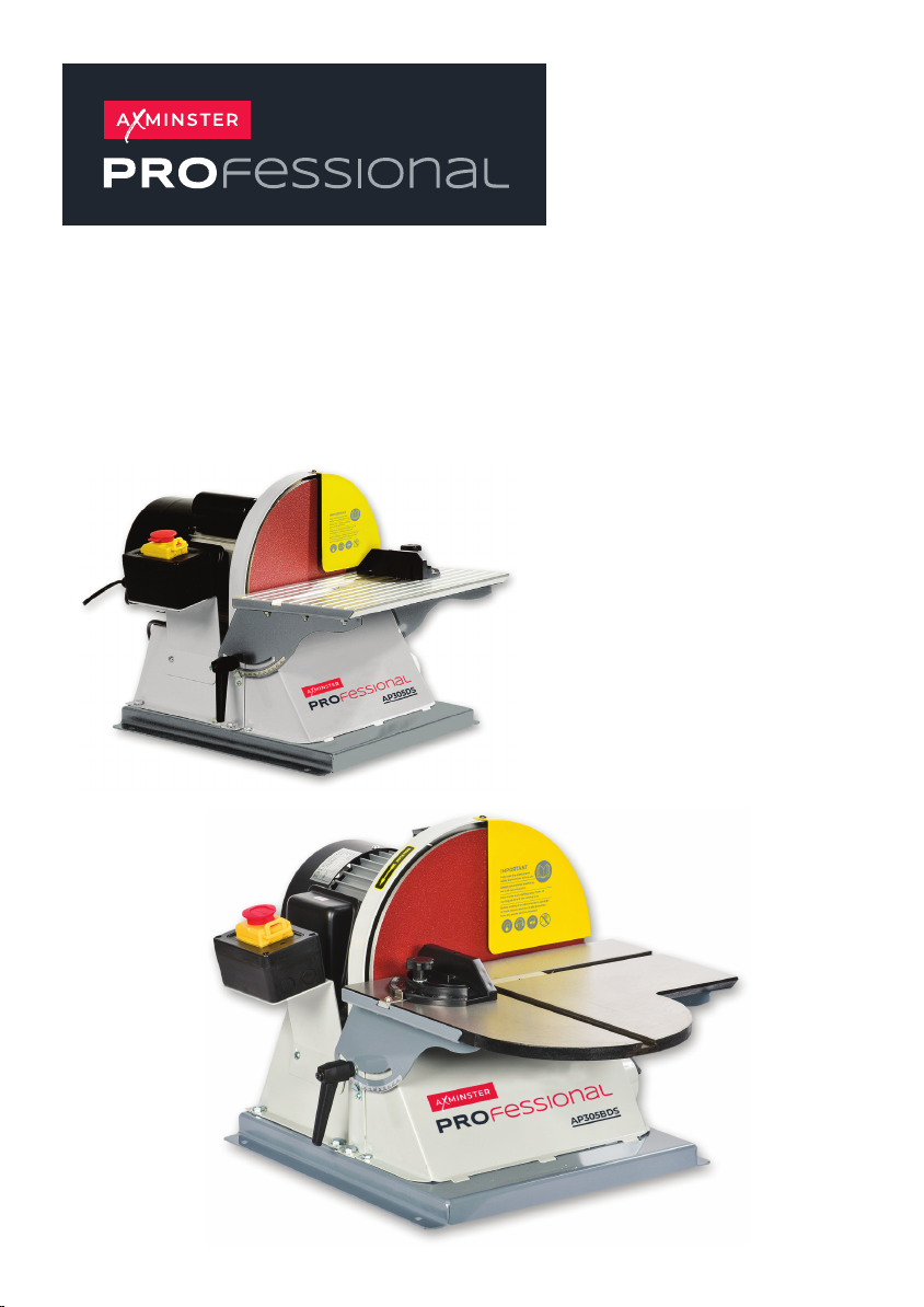
AP305DS 300mm
AP305BDS 305mm
Disc Sanders
AP305DS Code 107627
AP305BDS Code 107628
Original Instructions
Code: 107627
Code: 107628
AT: 30/07/205
BOOK REF: APT008149
BOOK VERSION: 6
Page 2
INDEX OF CONTENTS
EU Declaration of Conformity 02
What’s Included 03
General Instructions for 230V Machines 04
Specific to Sanding Machines 05
Specification 06
Assembly 06
Illustration & Parts Description 07
Setup/Adjustments 08-09
Changing the Sanding Disc 10-11
Maintenance 11
Troubleshooting 11
Exploded Diagrams/Lists 12-13-14-15
Wiring Diagram 16
Notes 17-18-19
EU DECLARATION OF CONFORMITY
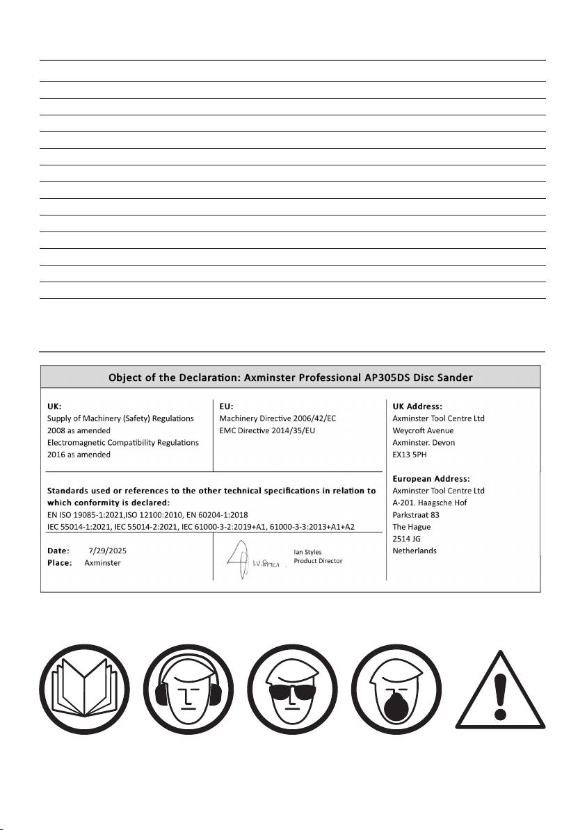
The symbols below advise the correct safety procedures when using this machine.
Fully read manual
and safety instructions
before use
Ear protection
should be worn
Eye protection
should be worn
2
Dust mask
should be worn
HAZARD
Motor gets hot
Page 3
WHAT’S INCLUDED
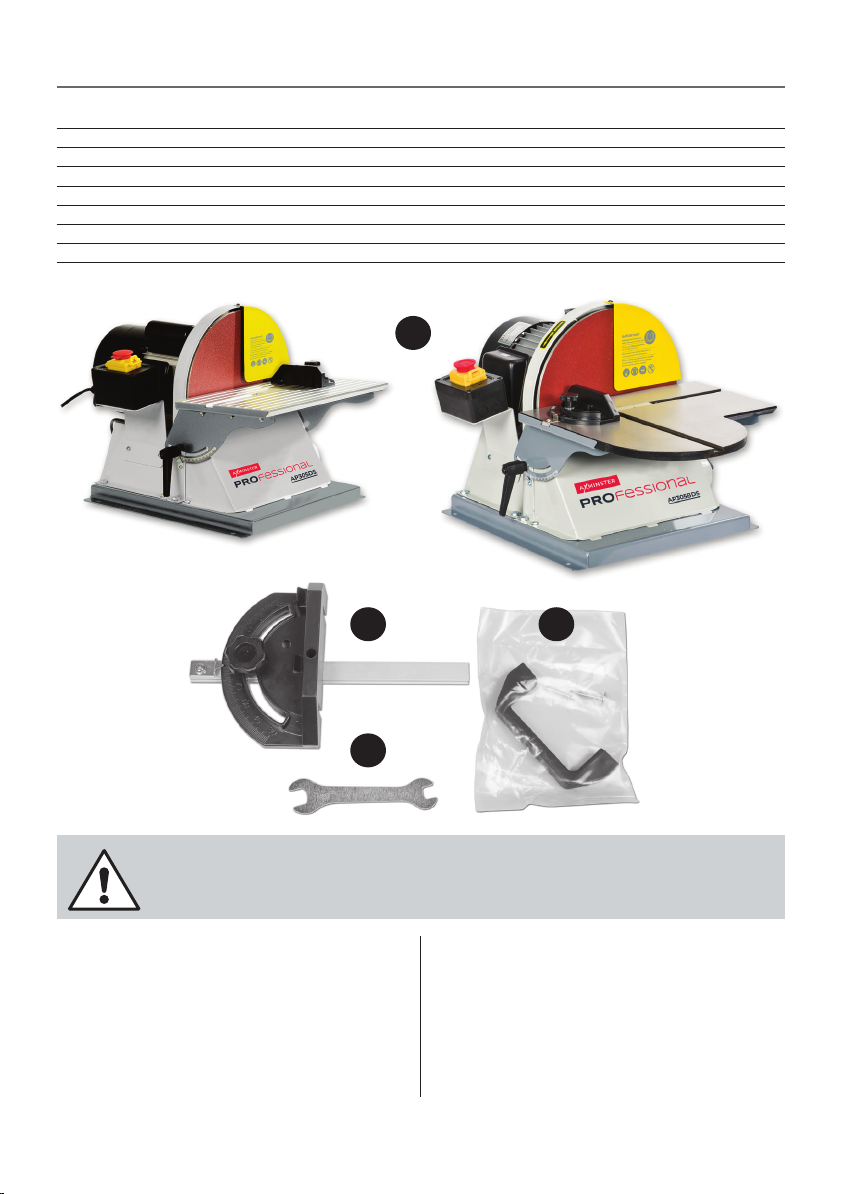
Quantity Item Part Model Number
1 No AP305DS 300mm & AP305BDS 305mm Disc Sander A
1 No Mitre Fence B
1 No 10-13mm spanner C
1 No Bag Containing D
Handle and two Screws
1 No Manual
AP305DS & AP305BDS
A
B
D
C
NOTE: Please read the Instruction Manual prior to using your new machine; as well as the
operating procedures for your new machine, there are numerous hints and tips to help
you to use the machine safely and to maintain its efficiency and prolong its life.
Having opened the box, remove all the components stowed
in the packaging. Place these carefully to one side.
Remove the top packaging and lift the machine out of the
box and place upon a clear flat surface, taking care not to
trap or pinch the power cable under the chassis.
Remove any other items from the box.
Having unpacked your sander and it’s various
components, if you do not wish to retain the packaging
please dispose of it responsibly, especially any
polystyrene; most of the rest of the packaging is
biodegradable.
Keep this Instruction Manual readily accessible for any others
who may also be required to use the machine.
3
Page 4
GENERAL INSTRUCTIONS FOR 230V MACHINES
Good Working Practices/Safety
The following suggestions will enable you to observe good
working practices, keep yourself and fellow workers safe and
maintain your tools and equipment in good working order.
WARNING! KEEP TOOLS AND
EQUIPMENT OUT OF THE REACH OF
YOUNG CHILDREN!
Mains Powered Tools (General) /Disc & Belt Sander
Primary Precautions
These machines are supplied with a moulded 13 Amp. Plug
and 3 core power cable. Before using the tool inspect the
cable and the plug to make sure that neither are damaged. If
any damage is visible have the tool inspected/repaired by a
suitably qualified person. If it is necessary to replace the plug,
it is preferable to use an ‘unbreakable’ type that will resist
damage on site.
Only use a 13 Amp plug, make sure the cable clamp is
tightened securely. Fuse at 5 Amp. It is also good practice
to use switched outlets. If extension leads are to be used,
carry out the same safety checks on them, and ensure that
they are correctly rated to safely supply the current that is
required for your machine.
This machine is intended primarily for inside/workshop
usage.
Work Place/Environment
Always mount the machine on a flat, level stable surface.
There are several methods of achieving this, bolting the
machine directly to a ‘good solid workbench’, bolting the
machine to a sturdy base board that can be clamped to the
‘good solid workbench’; create an independent entity by
bolting the machine to its own stand.
However when you mount your machine, make sure it is
ened down and stable before use.
fast
Paper belts and discs do not respond well to wet or damp
conditions. In the worst case the adhesives holding the belt
and the abrasive fail completely, the belts fall apart and the
abrasive becomes a soggy mess against the edge of your
work piece.
Try to keep the machine in a reasonably dry, warm
environment. If this is not possible; or if the machine is to
remain unused for some time, at least remove the belt, put in
a ‘plastic’ bag (your partner will take a dim view of sawdust
trails) and store in a warm dry place.
I’m afraid I can offer no suggestions for the disc, unless you
have upgraded to some form of ‘velcro’. fastening method, in
which case, do the same as with the belt.
(P.S. don’t forget…don’t leave the spare belts/discs in the
damp). Keep the work area as uncluttered as is practical, this
includes personnel as well as material.
UNDER NO CIRCUMSTANCES
SHOULD CHILDREN BE ALLOWED IN
WORK AREAS!
WARNING! THE SANDING DISC CANNOT
BE DECLUTCHED FROM THE BELT AND
VICE VERSA, BOTH FUNCTIONS ARE
ACTIVE WHEN THE MACHINE IS
RUNNING. REMEMBER THIS, AND DO
NOT LEAVE LOOSE OBJECTS OF ANY
DESCRIPTION, ON THE MACHINE IF IT IS
GOING TO BE USED!
4
Page 5

SPECIFIC TO SANDING MACHINES
Once the sander is mounted, carry out any setting
operations, (mitre, tilt..?), and remove all tools used in the
setting operations (if any) and place safely out of the way. If
you are working long lengths of material arrange for extra
support beyond the boundary of the machine, and check
you have sufficient room to manoeuvre the material through
all the operations you will wish to carry out.
It is good practice to leave the machine unplugged until
work is about to commence, also make sure to unplug the
machine when it is not in use. Always disconnect by pulling
on the plug body and not the cable.
After fitting a new sanding disc, it is good practice to lightly
sand across the left side of the disc with a reasonable sized
(20mm x 50mm) piece of timber to make sure the sanding
disc is correctly ‘seated’ on the disc. The sanding action will
press the sanding disc firmly back against the disc itself.
It is not good practice to wear gloves whilst sanding as one
tends to lose the ‘feel’ of the work piece/sander contact, but
obviously this removes the safety barrier between your
fingers and the sanding surface. Remain focused and
exercise caution whilst sanding.
DO NOT sand very small pieces of work with bare hands; try
to construct some form of holder.
MAKE SURE you are comfortable before you start work,
balanced, not reaching etc. If the work you are carrying out is
liable to generate excessive grit or dust or chips, wear
the appropriate safety clothing, goggles, masks etc., If the
work operation appears to be excessively noisy, wear eardefenders. If you wear your hair in a long style, wearing a cap,
safety helmet, hair net, even a sweatband, will minimise the
possibility of your hair being caught up in the rotating parts
of the machine, likewise, consideration should be given to
the removal of rings and wristwatches, if these are liable to
be a ‘snag’ hazard.
DO NOT work with cutting/abrasive tools of any description
if you are tired, your attention is wandering or you are being
subjected to distraction. A deep graze, a lost fingertip or
worse, is not worth it!
DO NOT use the machine within the designated safety areas
of flammable liquid stores or in areas where there may be
volatile gases. There are very expensive, very specialised
machines for working in these areas, THIS IS NOT ONE OF
THEM.
CHECK that sanding surfaces are still sufficiently abrasive
to carry out the work you intend. Sanding belt cleaning
sticks are an efficient method of prolonging the life of
the belts and discs, and will also maintain their operating
performance.
CHECK that the belts or discs are undamaged; torn edges
can pick up on the work piece and will cause the medium to
tear, often very rapidly with accompanying sharp flapping
edges.
ALWAY S offer the work piece to the belt/disc so that the
motion carries the work against the restraining surface, (i.e.
the work stop or the table, (use the left hand side of the disc).
DO NOT press too heavily against the sanding surface, all
this will do is slow the sander down. Remember, sanders
work by removing small particles of material quickly and
heavy pressure works adversely to the cutting process,
further, it will accelerate the rate of ‘clogging’ of the abrasive
surfaces, rendering the machine less efficient.
If you are attempting to sand inside curves (over the ‘tracking
drum’) do not press at all,other than to keep the work piece
in contact with the surface, any pressure could upset the
tracking geometry. As there is no cushioning effect to the
belt passing around the drum, expect an added vibration
and compensate for it.
Sanding of certain types of timber may make the fitting
of dust extraction mandatory in order to comply with the
directives of the HSE. However, even if it is not mandatory,
it is strongly recommended that you consider fitting dust
extraction. It will certainly reduce the level of dust and grit,
and as it helps to remove the waste quicker, will certainly
prolong the longevity of the abrasive.
Above all, OBSERVE…. make sure you know what is
happening around you, and USE YOUR COMMON SENSE.
5
Page 6
SPECIFICATION
Code 107267
Model AP305DS
Rating Professional
Power 560W (230V)
Plug Fitted UK 3 pin plug
Speed 1,450 rpm
Diameter of Disc 300 mm
Table Size 400 x 225 mm
Table Tilt 0° - 45
Min Extraction Airflow Required 390 m³/hr °
Dust Extraction Outlet 63 mm
Overall L x W x H 530 x 410 x 410 mm
Weight 28 kg
ASSEMBLY
In order to reduce the footprint of the machine for
packaging, several items are dismounted from the machine
and needs to be re-affixed.
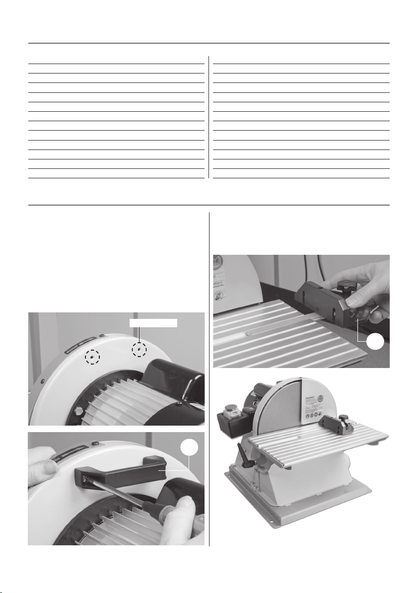
Step 1 Locate the plastic bag (D) containing the handle and
the two screws, line up the pre-drilled holes in the handle
with threaded holes to the rear of the sander and secure
using the two Phillips screws (See figs 1-2).
Fig 01-02
Threaded holes
Code 107628
Model AP305BDS
Rating Professional
Power 560W (230V)
Plug Fitted UK 3 pin plug
Speed 1,425 rpm
Diameter of Disc 305 mm
Table Size 400 x 225 mm
Table Tilt 0° - 45°
Min Extraction Airflow Required 390 m³/hr
Dust Extraction Outlet 63 mm
Overall L x W x H 671 x 445 x 410 mm
Weight 32 kg
Step 2 Locate the mitre fence (B) and slide it into the tables
‘T’ slot from the right side (See fig 3).
Fig 03
Disc sander assembled
6
Page 7
Model: AP305DS
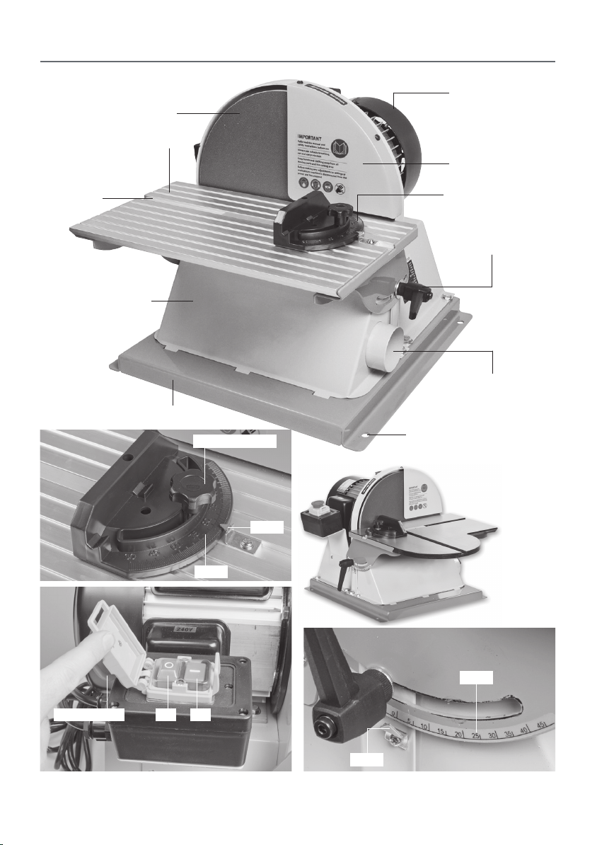
ILLUSTRATION & PARTS DESCRIPTION
Motor
Disc
Sanding table
Disc guard
‘T’ slot
Extraction housing
Base
Mitre fence clamp
Pointer
Scale
Mitre fence
Table clamping handle
Dust extraction outlet
Securing hole
Model: AP305BDS
OFF ONEmergency stop
Control Switch
Scale
Pointer
7
Page 8
SETUP/ADJUSTMENTS
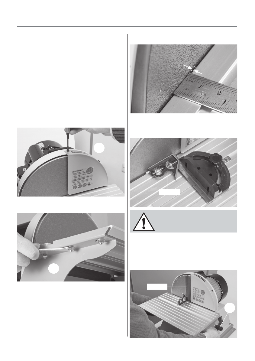
Setting the table clearance
The gap between the table and the disc should be set to
a maximum of 1.6mm to clear the debris and to ensure
sufficient support for the timber.
The table should be positioned so that sanding only occurs
from downward movement of the disc face. Small pieces of
timber should not be disc sanded. A responsible person
should check the setting of the machine before use.
Step 1 To set the table clearance, first remove the guard by
undoing the two screw (a), place screws and guard safely
aside (see fig 01).
Fig 01
Fig 02
Fig 03
Place a rule up against the sanding disc and adjust the table
until there is a clearance of 1.6mm.
Fig 04
90˚Square
NOTE: MAKE SURE THE MITRE
FENCE IS SET TO ZERO ON THE
SCALE!
Step 5 Place the square upright against the sanding disc,
loosen the two clamping handles (b) on either side of the
table and adjust the tables angle, until it’s perpendicular to
the sanding disc (see fig 05). Tighten the clamping handles.
Fig 05
Step 2 Locate the supplied spanner (C) loosen the six nuts
beneath the table brackets, (see fig 02) place a rule up
against the sanding disc and adjust the table until there is a
1.6mm clearance between the table and the disc, (see fig 03).
Step 3 Replace the disc guard as described above.
Step 4 Place the 90˚ square against the disc and mitre fence,
(see fig 04) to check the table is square then tighten the six
nuts beneath the table.
90˚Square
8
Page 9
SETUP/ADJUSTMENTS
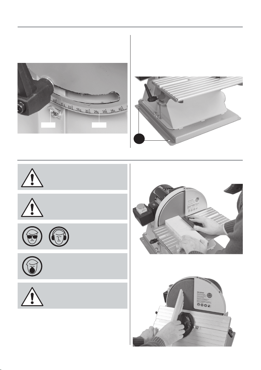
Step 6 Check the pointer is set to ZERO on the tables scale
and adjust until correct (see fig 6).
Fig 06
Pointer Scale
WARNING! KEEP TOOLS AND
EQUIPMENT OUT OF THE REACH
OF YOUNG CHILDREN!
CLEAR ALL TOOLS AWAY FROM
SANDING AREA!
Securing the Sander
It is recommended to secure the sander to a work bench or
stand using the four pre-drilled holes (d) in the chassis, (see
fig 07).
Fig 07
d
OPERATING INSTRUCTIONS
Sanding Configurations
Disc Sanding
Fig 08
WARNING! WEAR EYE
AND EAR PROTECTION!
WARNING! WEAR A DUST MASK!
CONNECT THE SANDER TO THE
MAINS AND SWITCH ON.
Don’t press too heavily against the sanding surface, all this
will do is slow the sander down. Remember, sanders work
by removing small particles of material quickly and heavy
pressure works adversely to the cutting process, further, it
will accelerate the rate of ‘clogging’ of the abrasive surfaces,
rendering the machine less efficient.
Bevel Sanding
9
Fig 09
Page 10
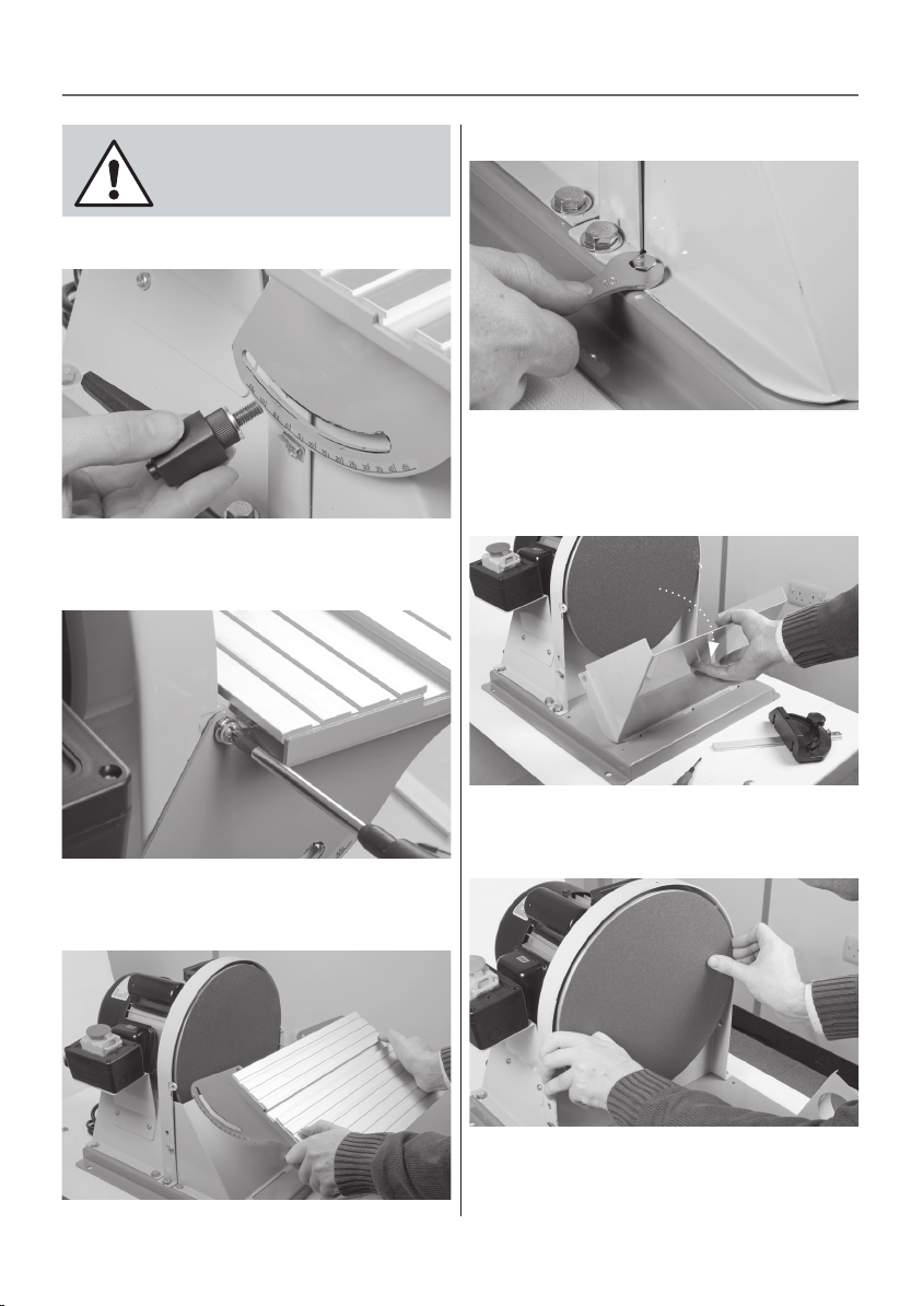
CHANGING THE SANDING DISC
DISCONNECT THE SANDER FROM
THE MAINS SUPPLY BEFORE
CONTINUING!
Fig 10
Step 1 Remove the two table clamping handles (see fig 10).
Fig 11
Fig 13
Step 4 Locate the supplied spanner (C) and using the 10mm
end remove the two nuts on either side of the extraction
housing (see fig 13)
Fig 14
Step 2 Remove both screws on either side of the table and
place safely aside (see fig 11).
Fig 12
Step 3 Lift the table assembly away and place to one side
(see fig 12).
Step 5 Lower the extraction housing (see fig 14).
Fig 15
Step 6 Grip the edge of the adhesive disc and peel away
from the plate; turning the plate as required to free the
entire disc (see fig 15). Clean the surface of the disc with a
de-greasing cleaner. Allow to dry off and wipe over with a
10
Page 11
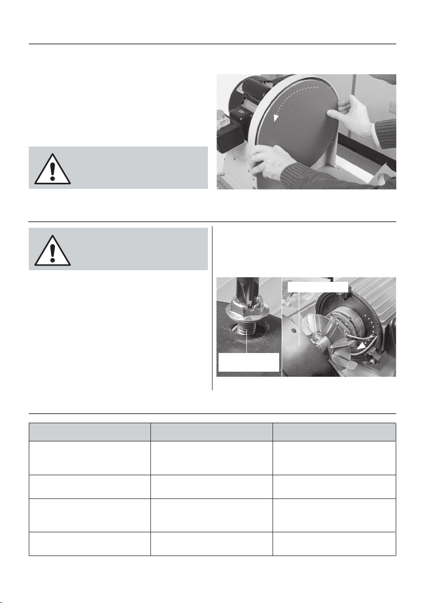
CHANGING THE SANDING DISC
clean dry cloth. Locate the sanding disc, peel the cover from
the adhesive surface and apply CAREFULLY to the disc (see
fig 16). Use a piece of cloth in your hand or wear a glove, to
firmly press the abrasive to the disc, the application will be
reinforced by a gentle sanding action across the face when
you first use the new sanding disc.
Step 7 Re-assemble the sander as described opposite but in
reverse (see figs 10 to 14).
RECONNECT THE SANDER TO THE
MAINS SUPPLY AND CONTINUE
WITH OPERATION.
DISCONNECT THE SANDER FROM
THE MAINS SUPPLY BEFORE
CONTINUING!
There is very little mechanical maintenance that can be
carried out on the machine. Most prudent maintenance
is preventative and concerned with keeping the machine
clean.
1. At reasonable intervals, inspect and remove all dust/resin
build ups, and blow the motor clean.
2. Remove the table assembly and lower the extraction
housing, clean any dust or resin build up. Re-assemble the
sander.
Fig 16
Turn the disc while applying pressure
MAINTENANCE
3. Inspect the sanding disc for signs of wear and tear and
replace if necessarily.
4. From time to time using a damp cloth wipe over the
sanders surface.
Motor rear guard
Remove the three
Phillips screws
Remove the rear guard and blow the motor clean
TROUBLE PROBABLE CAUSE REMEDY
Motor does not run when power
switch is pressed “ON”
Motor does not run at full speed 1. Power voltage is too low
Motor does not reach full power 1. Incorrect power wiring
Motor overheating 1. Motor voltage is different
1. Switch is burnt out
2. Connection wire is loose or
damaged
2. Motor is damaged.
2. Overloaded
2. Motor is damaged
11
TROUBLESHOOTING
1. Replace the switch
2. Tighten wire or replace
1. Test voltage
2. Check and repair motor
1. Replace with the correct size of
power wiring
2. Reduce load
1. Check the voltage label
2. Check and repair the motor
Page 12
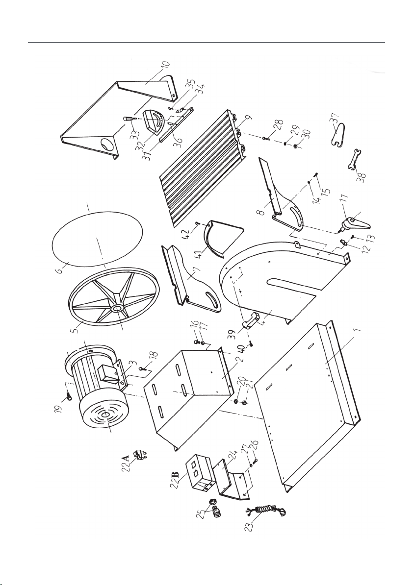
EXPLODED DIAGRAMS/LISTS
Model: DS12DL (AP305DS)
12
Page 13
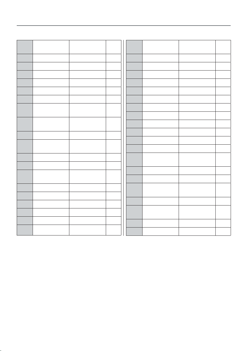
Model: DS12DL (AP305DS)
PART NODESCRIPTION SPECIFICATION QTY
EXPLODED DIAGRAMS/LISTS
PART NODESCRIPTION SPECIFICATION QTY
1 Base 1
2 Motor Base 1
3 Motor 3/4 HP 1
4 Disc Cover 1
5 Disc 12” 1
6 Sanding Paper 12” 1
7 Left Tilting
Turing
8 Right Tiltin
Tuming
9 Table Aluminum 1
10 Dust Hood
Cover
11 Handle M8xl6 2
12 Pointer 1
13 Hex. Head
Screw
14 Washer M6 2
15 Pan Head Screw M6x8 2
16 Pan Head Screw M8xl2 6
17 Washer M8 6
18 Pan Head Screw M8x25 4
19 Pan Head Screw M8x20 2
M4x8 1
20 Washer M8xl8 4
21 Nut M8 4
22A Switch UL 1
22B Switch CE 1
23 Power Cord 1
28 Pan Head Screw M6x20 6
1
1
1
29 Washer M6xl3 6
30 Nut M6 6
31 Mitre Bar 1
32 Mitre Gauge 1
33 Bolt 1/4” 1
34 Pointer 1
35 Hex. Head
Screw
36 Pin 5x20 1
37 Spanner 1
38 Open End
Wrench
39 Handle 1
40 Hex. Head
Screw
41 Safety Guard 1
42 Pan. Head Screw 5x8 2
3/16”x3/8” 1
10~13mm 1
M6x20 2
13
Page 14
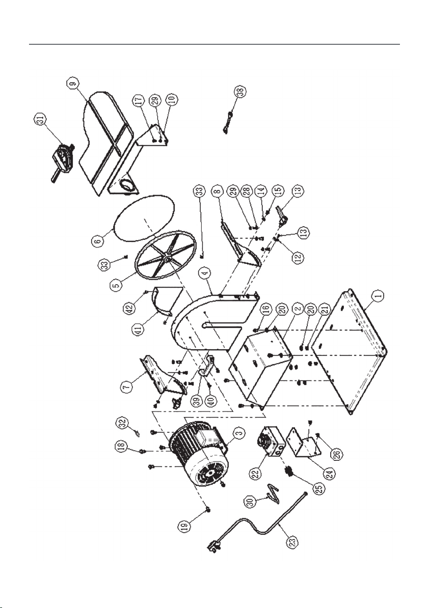
EXPLODED DIAGRAMS/LISTS
Model: DS12DLMB2 (AP305BDS)
14
Page 15
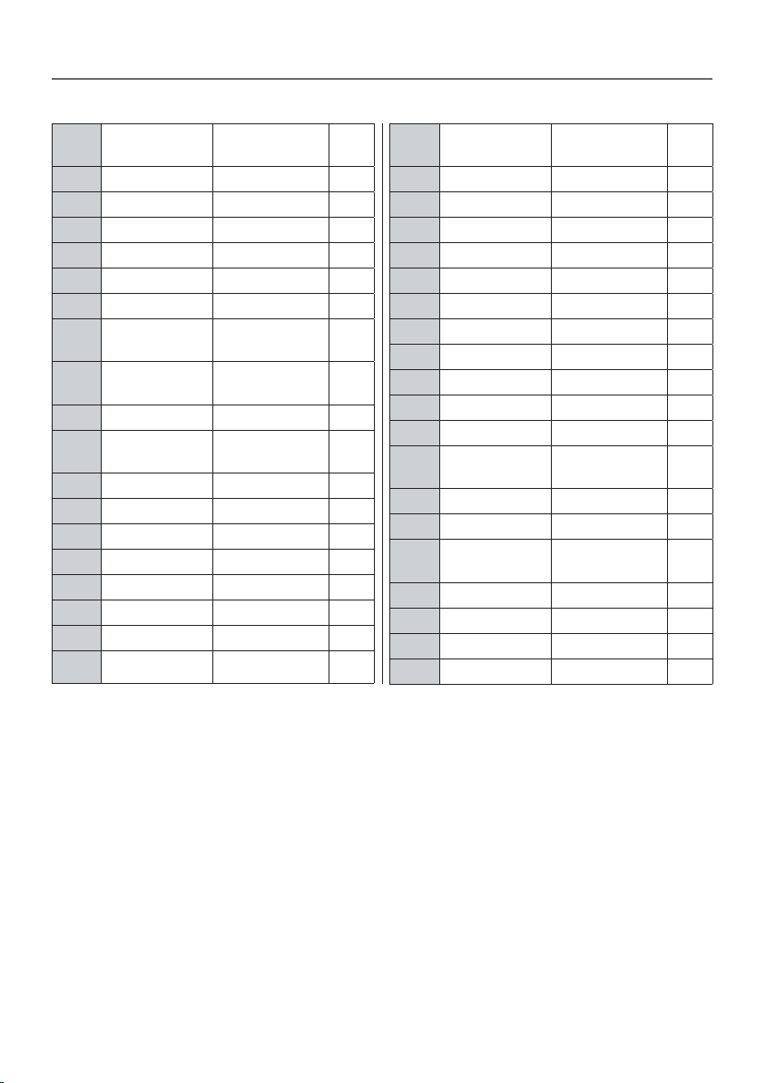
Model: DS12DLMB2 (AP305BDS)
PART NODESCRIPTION SPECIFICATION QTY
EXPLODED DIAGRAMS/LISTS
PART NODESCRIPTION SPECIFICATION QTY
1 Base 1
2 Motor Base 1
3 Motor 3/4HP 1
4 Disc Cover 1
5 Disc 12” 1
6 Sanding Paper 12” 1
7 Left Tilting
Turning
8 Right Tilting
Turning
9 Cast iron Table 1
10 Dust Hood
Cover
11 Handle M8x16 2
12 Pointer 1
13 Pan Head Screw M4x8 1
14 Washer 1/4” 2
15 Pan Head Screw M6x10 2
16 Hex Head Screw M8x12 6
17 Hex Head Screw M6x10 2
18 Hex Head Screw M8x25 4
19 Hex Head Screw M8x16 2
20 Washer 5/16”x18 10
21 Nut M8 4
22 Switch 1
23 Power Cord 1
24 Switch Board 1
1
1
1
25 Wire protectors 1
26 Pan Head Screw M6x12 2
28 Hex Head Screw M6x16 6
29 Washer 1/4x13 8
30 Motor cable 1
31 T-indexing
plate
32 Bond 6x6x25 1
33 Set Screw M8x10 2
38 Open End
Wrench
39 Handle 1
40 Pan Head Screw 1/4”x5/8” 2
41 Safety Guard 1
42 Pan Head Screw 5x8 2
10~13mm 1
1
15
Page 16
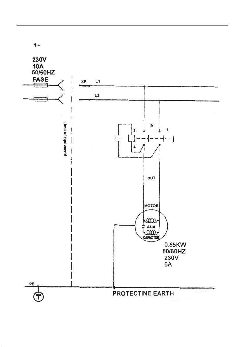
WIRING DIAGRAM
16
Page 17

NOTES
17
Page 18

NOTES
18
Page 19

NOTES
19
Page 20

The packaging is suitable for recycling.
Please dispose of it in a responsible manner.
EU Countries Only
Do not dispose of electric tools together with household waste material.
By law they must be collected and recycled separately.
Axminster Tools, Axminster Devon EX13 5PH
axminstertools.com
 Loading...