

Page 1
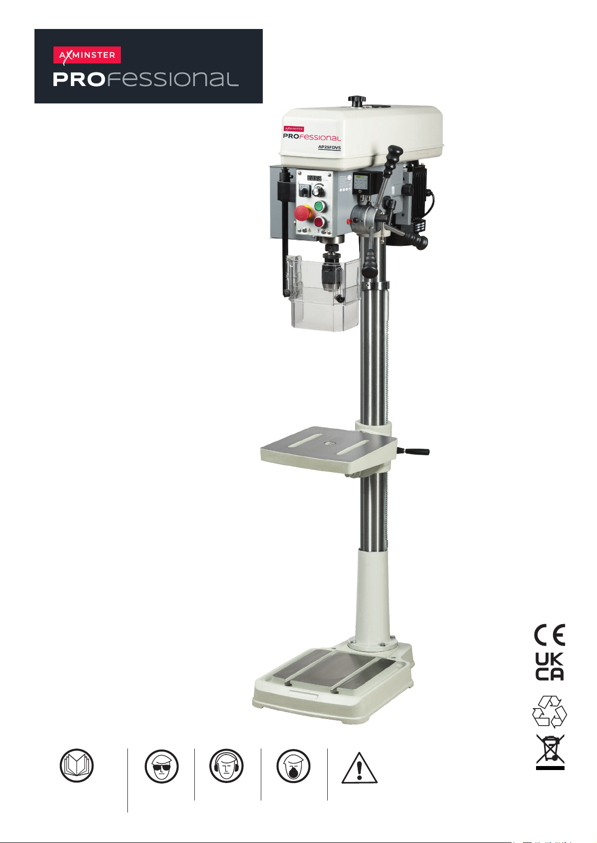
AP25FDVS
Variable Speed
Pillar Drill
Code 111890
Original Instructions
Fully read manual and safety
instructions before use. Save this
manual for future reference.
Eye protection
should be worn
The symbols above advise the correct safety procedures when using this machine.
Ear protection
should be worn
Dust mask
should be worn
Hazard
The packaging is suitable for recycling.
Please dispose of it in a responsible manner.
Do not dispose of electric tools together with
household waste material. By law they must be
collected and recycled separately.
EU Countries Only
AT: 29/9/2025
Book Version: 03
Page 2

Operating Instructions
However, any machine used improperly
result in severe injury from breakage
maintain proper working position can
cause you to fall into the machine or
environments. Do not use stationary
Avoid accidental starts by being sure
Dear Customer,
Many thanks for the confidence you have shown in us with the purchase of your new machine. This manual has been prepared for
the owner and operators of a VS drilling machine to promote safety during installation, operation and maintenance procedures.
Please read and understand the information contained in these operating instructions and the accompanying documents. To obtain
maximum life and efficiency from your machine, and to use the machine safely, read this manual thoroughly and follow instructions
carefully.
…Table of Contents
1. Warranty
2. Safety
Warnings
Machinery General Safety Warnings
Safety Instructions for Drill Presses
3. Machine specifications
Technical data
Noise emission
Contents of delivery
4. Transport and start up
Transport and installation
Positioning the machine
Anchoring the machine
Minimum housing requirements
Assembling loose parts
Electrical connection of the machine
5. Machine operation
Controls
Depth indicator
Operation cycle
Chosing the spindle speed
6. Machine adjustments
Adjusting table and rack height
Adjusting headstock height
Radial head position adjustment
Belt adjustment
Tool installation and uninstallation
The spindle shield
7. Operating precautions
8. Maintenance
9. Environmental protection
10. Available accessories
11. Declaration of conformity
1. Warranty
TOOL guarantees that the supplied
product(s) is/are free from material
defects and manufacturing faults.
This warranty does not cover any
defects which are caused, either directly
or indirectly, by incorrect use,
carelessness, damage due to accidents,
repairs or inadequate maintenance or
cleaning as well as normal wear and
tear.
2 Safety
2.1 Warnings
- Misuse of this machine can cause
serious injury.
- For safety, machine must be set up,
used and serviced properly.
- Read, understand and follow
instructions in the Operating
Instructions and Parts Manual which
was shipped with your machine.
When setting up machine:
- Always avoid using machine in
damp or poorly lighted work areas.
- Always be sure the machine support
is securely anchored to the floor or
the work bench.
When using machine:
- Always wear safety glasses with
side shields
- Never wear loose clothing or jewelry.
- Never overreach—you may slip and
fall.
When servicing machine:
- Always disconnect the machine from
its electrical supply while servicing.
- Always follow instructions in
Operating Instructions and Parts
Manual when changing accessory
tools or parts.
- Never modify the machine without
consulting .
You—the stationary power tool user—
hold the key to safety.
Read and follow these simple rules for
best results and full benefits from your
machine. Used properly, machinery is
among the best in design and safety.
can be rendered inefficient and unsafe.
It is absolutely mandatory that those
who use our products be properly
trained in how to use them correctly.
They should read and understand the
Operating Instructions and Parts
Manual as well as all labels affixed to
the machine. Failure in following all of
these warnings can cause serious
injuries.
2.2 Machinery General Safety
Warnings
1. Always wear protective eye wear
when operating machinery. Eye
wear shall be impact resistant,
protective safety glasses with side
shields which comply with ANSI
Z87.1 specifications. Use of eye
wear which does not comply with
ANSI Z87.1 specifications could
of eye protection.
2. Wear proper apparel. No loose
clothing or jewelry which can get
caught in moving parts. Rubber
soled footwear is recommended for
best footing.
3. Do not overreach. Failure to
cause your clothing to get caught,
pulling you into the machine.
4. Keep guards in place and in proper
working order. Do not operate the
machine with guards removed.
5. Avoid dangerous working
machine tools in wet or damp
locations. Keep work areas clean
and well lit.
6.
the start switch is "OFF" before
plugging in the machine.
7. Never leave the machine running
while unattended. Machine shall be
shut off whenever it is not in
operation.
2
Page 3
8. Disconnect electrical power before
servicing. Whenever changing
accessories or general maintenanc
is done on the machine, electrical
power to the machine must be
disconnected before work is done.
9. Maintain all machine tools with care.
Follow all maintenance instructions
for lubricating and the changing of
accessories. No attempt shall be
made to modify or have makeshift
repairs done to the machine. This
not only voids the warranty but als
o
renders the machine unsafe.
10. Machinery must be anchored to the
floor.
11. Secure work. Use clamps or a vise
to hold work, when practical. It is
safer than using your hands and it
frees both hands to operate the
machine.
12. Never brush away chips while the
machine is in operation.
13. Keep work area clean. Cluttered
areas invite accidents.
14. Remove adjusting keys and
wrenches before turning machine on.
15. Use the right tool. Don't force a tool
or attachment to do a job for which it
was not designed.
16. Use only recommended accessories
and follow manufacturer's
instructions pertaining to them.
17. Keep hands in sight and clear of all
moving parts and cutting surfaces.
18. All visitors should be kept at a safe
distance from the work area. Mak
e
workshop completely safe by using
padlocks, master switches, or by
removing starter keys.
19. Know the tool you are using — its
application, limitations, and potential
hazards.
Familiarize yourself with the following
safety notices used in this manual:
This means that if
precautions are not heeded, it may
result in minor injury and/or possible
machine damage.
1. All work shall be secured using
either clamps or a vise to the drill
e
press table. It is unsafe to use your
hands to hold any workpiece bei
drilled.
2. Drill press head and table shall be
securely locked to the column before
operating the drill press. This must
always be checked prior to starti
the machine.
3. Always use the correct tooling.
Tooling shall always be maintained
and properly sharpened. All tooling
must be run at the proper speeds
and feeds as they apply to the job.
Use only recommended accessories
and follow those manufacturer's
instructions pertaining to them.
Tooling shall not be forced in to any
work piece but fed according to the
proper specifications. Failure t
follow these instructions will not only
ruin the tooling as well as the
machine, but can cause serious
injury.
4. Never brush away any chips while
the machine is in operation. All clean
up should be done when t
machine is stopped.
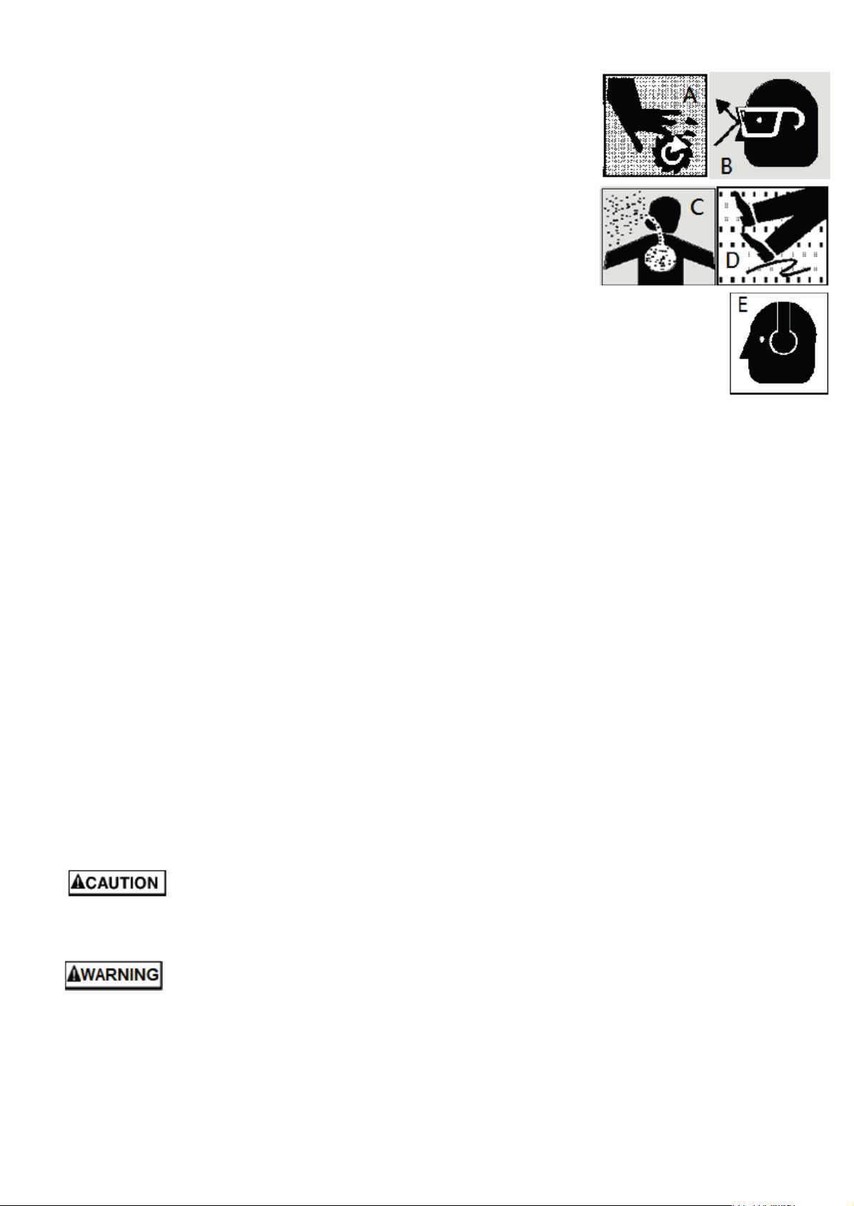
5. Keep hands in sight. Do not put
hands or fingers around, on, or
below any rotating cutting tools.
Leather safety gloves should
used when handling any sharp
objects or cutting tools. See Figure
A.
6. Always wear protective eye wear
when operating, servicing or
adjusting machinery. Eyewear shall
be impact resistant, protective safety
glasses with side shields. Figure B.
7. When drilling in material which
causes dust, a dust mask shall be
worn. See Figure C.
8. Avoid contact with coolant,
especially guarding the eyes.
9. Non-slip footwear and safety shoe
are recommended. See Figure D.
10. Wear ear protectors (plugs or muffs)
during extended periods of operation.
See Figure E.
ng
ng
o
he
be
s
This means that if
precautions are not heeded, it may
result in serious or even fatal injury.
3.3 Safety Instructions for Drill
Presses
3
Page 4
3.Machine specifications
The head and the worktable of the
with a mild solvent e.g. petroleum.
Position the machine on a firm and
3.1 Technical data
ZS1720B-VS:
Drilling Capacity Mild Steel 20mm
Tapping Capacity Mild Steel M12
Chuck Size…B16 1-16mm
Spindle Travel 100mm
Distance Spindle to Base 540mm
Distance Spindle to Table (max)300mm
Table Size 283×248mm
Table Travel 224mm
Table Tilt ± 45 °
Work Table Weight Capacity 60kg
Head Travel 345mm
Spindle Taper MT-2
Column Diameter/ Material Ø70mm /
Cast Iron
Number of Spindle Speeds Variable
Pulleys Material Cast Iron
Spindle Speeds Range
0-2100RPM
Base Size 345×520mm
Base Work Area 258×275mm
Spindle Distance to Column 203mm
Net weight 96 kg
Mains 400V ~3L/PE 50Hz
Output power 0,55 kW S1
Reference current 1,8A
Extension cord : 4G0.75mm²
Installation fuse protection 10A
ZS1725F-VS:
Drilling Capacity Mild Steel 25mm
Tapping Capacity Mild Steel M12
Chuck Size…B16 1-16mm
Spindle Travel 100mm
Distance Spindle to Base 1160mm
Distance spindle to Table (max) 850mm
Table Size 320×320mm
Work Table Weight Capacity 60kg
Spindle Taper MT-2
Column Diameter/ Material Ø80mm /
Steel Tube
Number of Spindle Speeds Variable
Pulleys Material Cast Iron
Spindle Speeds Range
50-2100RPM
Base Size 600×385mm
Spindle Distance to Column 196mm
Net weight 115 kg
Mains 400V ~3L/PE 50Hz
Output power 0,55 kW S1
Reference current 1.8A
Extension cord (H07RN-F): 4G1,0mm²
Installation fuse protection 10A
3.2 Noise emission
Acoustic pressure level (EN 11202):
Idling at maximum speed 75 dB (A)
The specified values are emission levels
and are not necessarily to be seen as
safe operating levels.
As workplace conditions vary, this
information is intended to allow the user
to make a better estimation of the
hazards and risks involved only.
3.3 Content of delivery
B16 1-16mm drill chuck with arbor
Head rising crank and handle
Operating tools
Operating manual
Spare parts list.
4.Transport and start up
4.1 Transport and installation
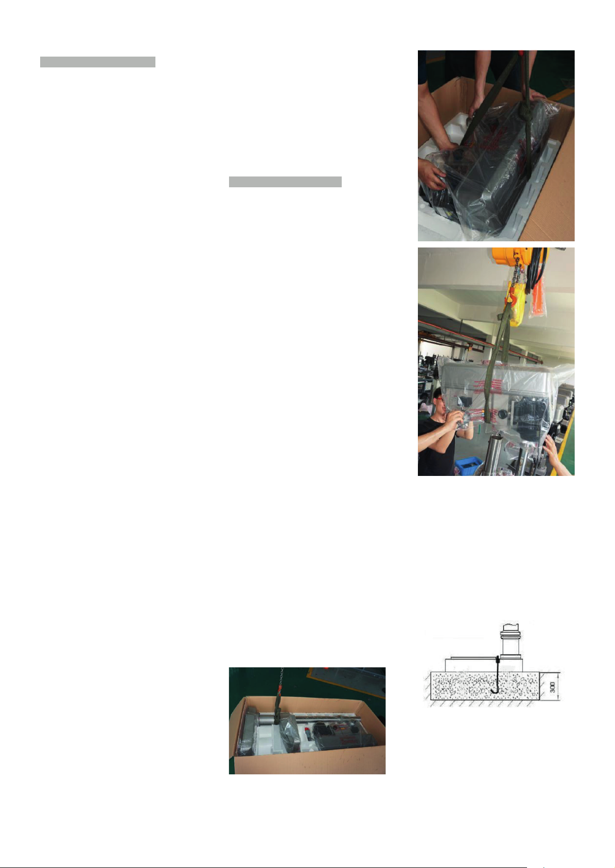
The machine will be delivered in a
reliable carton
For transport use a forklift or hoist.
Make sure the machine does not tip or
fall off during transport.
Danger of tipping due to high gravity
center!
During handling, the machine shall be
lifted only in vertical direction.
Please refer to instruction manual in
specification and machine weight to
arrange handling manner. Be sure to
use capable fork - lifter or hoist to lift of
machine. The handling and
transportation shall be carried out by
qualified persons. Fork - lift or hoist can
be used in handling and shall be
operated by qualified driver.
Before handling, make sure all movable
parts are secured in their position and
all movable accessories should be
removed from machine. The steel rope
should average pull the machine head,
table and column tightly.
Keep all the processes in a carefully
and slightly condition. Bump or crash
are strictly prohibited. It will cause
precision shift and electronic controller
damaged.
4.2 Positioning the Machine
I. Owing the machine is heavy,
please use crane to pull it out from
the carton box.
II.
machine can be rotated 360°, so
choose a location with enough
space and solid foundation.
III. Clean all rust protected surfaces
4.3 Anchoring the Machine
Assure the sufficient load capacity
and proper condition of your lifting
devices.
I.
level concrete floor.
4
Page 5
II. A minimum distance of 800mm
Drilling/Tapping Selector: Selects
RPM Display: Displays the rate of
)
)
Change speeds only while the machine
towards a rear wall must be kept
(for access to the electrical box).
III. Anchor the machine to the ground,
as shown in the diagram, using
screws and expansion plugs or
sunken tie rods that connect
through holes in the base.
4.4 Minimum Requirement for Housing
the Machine
Please comply with the following terms
to maximize the life and performance of
the machine and its components.
The Main voltage and frequency
complying with the requirements for the
machine's motor.
Environment temperature from -10°C to
+50°C.
Relative humidity not over 90%.
4.5 Assembling Loose Parts
Attach Riser handle to the necessary
crankshaft, and use Hex-wrench to
tighten/loosen the machine head lock
nut.
4.6 Electrical Connection of the
Machine
Make sure whether the voltage 400V
matches the requirement for the
machine, prior to connection to power
supply. If the machine cannot be
operated after wires have been
connected, please check the following
items:
I. Is the Emergency switch released?
II. Is the door of the electrical cabinet
is properly closed and switched ON
(locked) position?
III. Is the safety guard in the proper
position (closed)?
5. Machine operation
Warning:
Setup work may only be carried out
after the machine is protected
against accidental starting.
With pressed emergency stop
button.
Never place your fingers in a position
where they could contact any rotating
tool, chuck or cutting chips.
Remove cutting chips with the aid of an
appropriate chip hook when the
machine is at a standstill only.
Never stop the rotating chuck or tool
with your hands.
Always close the chuck guard and
pulley cover before you start the
machine.
Secure workpiece to the table with
clamps or a vice to prevent rotating with
the drill bit.
When using a vice, always fasten it to
the table.
Check the save clamping of the
workpiece, chuck and tools before
starting the machine.
Never do any works “freehand” (handholding the work piece rather than
supporting it on the table).
Support long workpieces with helping
roller stands.
Always adjust the depth stop to prevent
drilling into the table or into the
worholding device.
Feed a drill bit into the material with only
enough force to allow the drill bit to
work. Feeding too slowly may cause
burning of the workpiece or tool.
Feeding too quickly may cause the
motor to stop and/or the drill bit to
break.
Do not use wire wheels or grinding
wheels on this machine.
Never cut magnesium-
high danger to fire!
Measurements and adjustments may be
carried out when the machine is at a
standstill only.
In case of danger push the
emergency stop button.
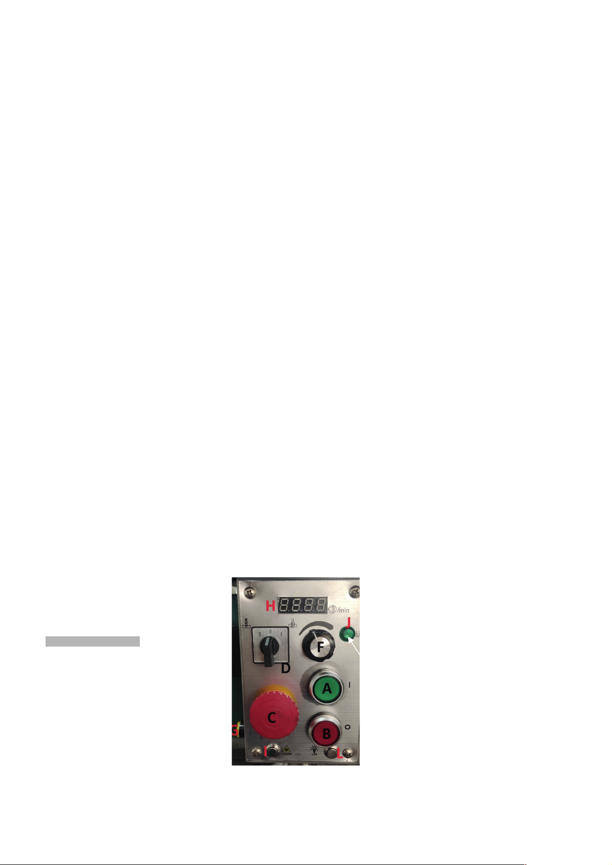
6.1 Controls
A. Spindle ON Switch: Starts the
motor.
B. Spindle OFF Switch: Stops the
motor. As the power still exists,
pressing ON restarts the
machine.
C. Emergency Stop Switch: Stops
the machine. Turn the switch
clockwise to unlock the switch
before starting the machine.
D.
the mode of operation
H.
spindle rotation in RPM.
F.Speed control button: Change the
speed of the spindle.
I . Laser light(optional accessory
L. LED light ( optional accessory
J. Indicator light
is running. Then spindle speed can be
adjusted to the proper cutting RPM by
using the spindle speed handle (F in
figure). The spindle speed ranges is
from 100 to 2100 rpm.
5
Page 6
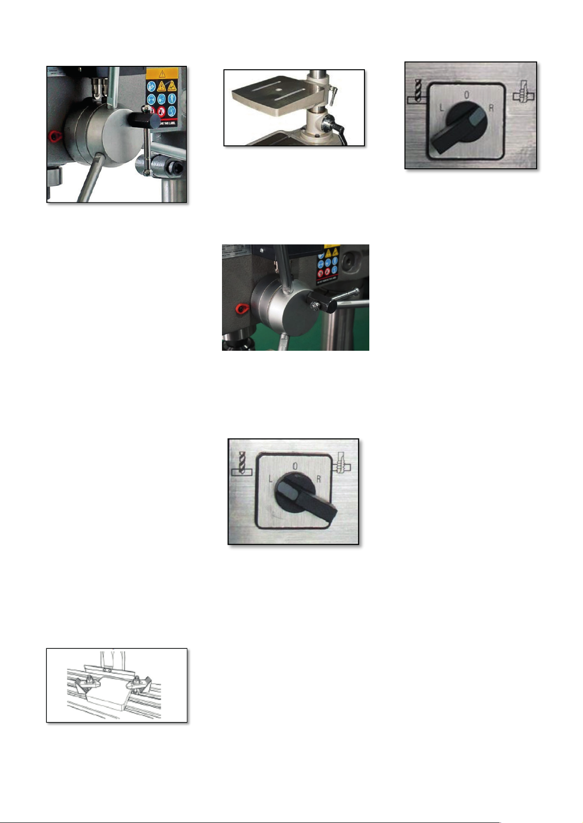
5.2 Depth Indicator
low speed which is lower than 200 rpm.
down feed at the bottom of operation to
In general, use low speeds for tapping.
Tapping requires an accurate setting
The speed recommendations apply to a
tool diameter of 10mm and a machining
speed steel (HSS) tool (e.g.
A drilling depth indicator is provided on
the side of the drill head. The lock knob
is provided at the side, on the top of
quill lever.
Before starting the motor:
I. Set the depth to zero by lowering
and holding the cutting tools to
the surface of the work piece.
Use quill lever to lower the
spindle.
II. Unlock the depth scale by turning
the lock knob.
III. Set the depth stop by rotating the
depth stop stud to the desired
depth.
IV. Lock the depth scale by turning
the lock knob.
5.3 Operation Cycle
Safety chuck guard must be in position,
electric box must be closed and locked,
and unlock emergency stop switch (C)
by turning the red cap of the switch
clockwise to start machine. In a critical
condition, stop machine by hitting
emergency stop switch or Spindle OFF
switch (B) to stop machine.
1. Check if the head is secured.
Failure to secure the head can result
in damage of the machine and
personal injury.
2. Secure the work piece to the table.
3. Use crankshaft to adjust the table
to the desired height.
4. Use lock-lever to secure the table.
5. Use the spindle/quill feed lever to
bring the drill or tapping tip down to
the surface of the work piece and
hold.
6. Set the depth indicator/stop to
required depth.
7. Back the drill or tapping tip off the
work piece a bit.
8. Select drilling or tapping mode.
9. Press Spindle ON switch to begin
spindle rotation.
In Drilling Mode
10. Use the depth handle to bring the
tip of the drill bit to the surface of
the work piece hold.
11. The required depth is set by
previous steps 5 and 6.
12. Select proper speed.
13. Begin drilling by using the quill feed
lever.
In Tapping Mode
In general, speeds for tapping require
14. Use the depth handle to bring the
tip of the tapping bit to the surface
of the work piece and hold.
15. The required depth is set by
previous steps 5 and 6.
16. Select the spindle speed.
17. Begin tapping by using the quill
feed levers.
18. At the end of a tapping or drilling
operation, press the stop button
switch to turn off the machine.
Note: While tapping, pause spindle
allow the breaking and reversal of
rotation of the spindle.
Tapping at high speed will tap more
quickly, but there is a danger of
damage to work piece and tool.
for the depth stop to allow the
machine to switch tapping direction
and the removal of the tapping bit.
6.4 Choosing the spindle speed
The correct spindle speed depends on
the type of machining, the workpiece
material as well as the tool diameter
and material.
with a highspiral drill).
Aluminum, brass 1500 rpm
Grey cast iron: 1000 rpm
Steel (C15): 800 rpm
Steel (C45): 600 rpm
Stainless steel: 300 rpm
6
Page 7
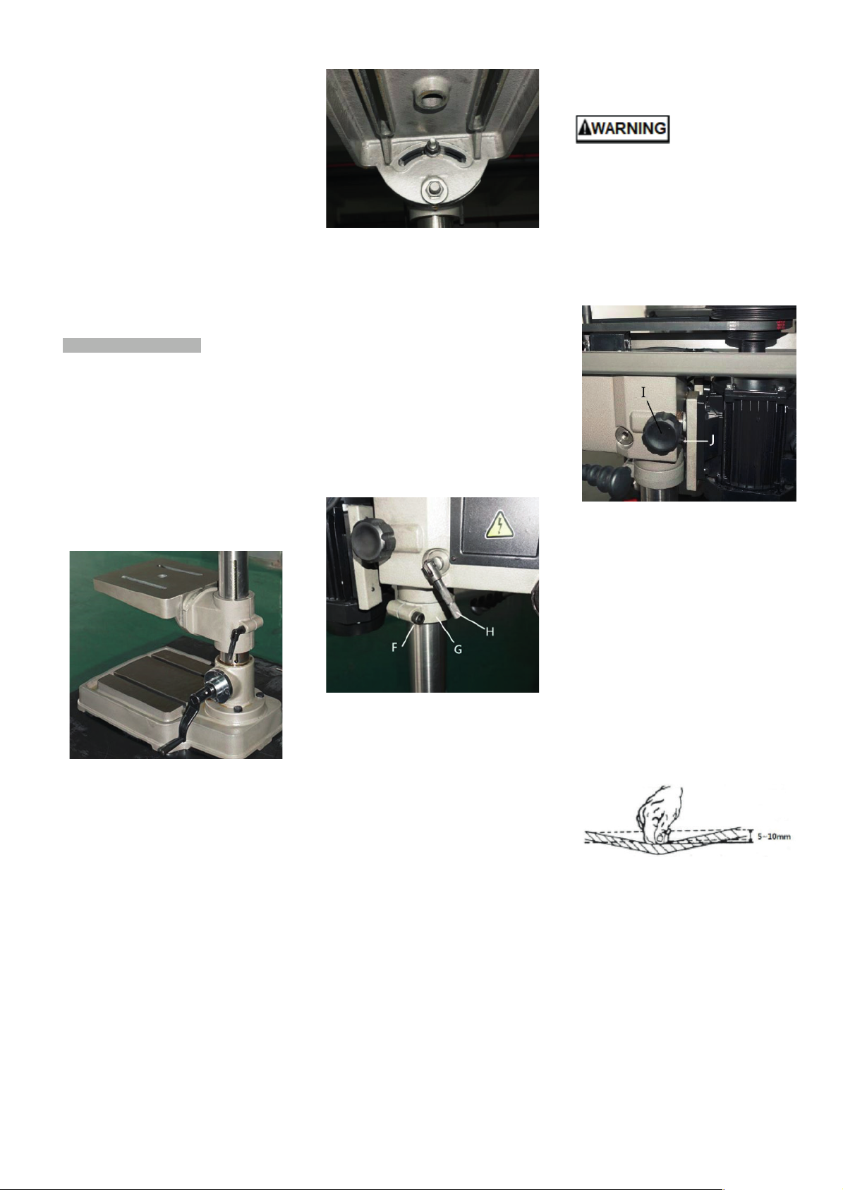
When using a carbide (HM) tool,
Radial Head Position Adjustment
floor. Swinging the drill head without
injury and/or damage to the machine.
10mm movement
approx. 5 times the speed is
permissible.
6.3
Generally speaking:
In proportion, the larger the rotation
diameter, the lower the possible speed.
For example:
Steel (C15) with 20mm diameter allows
a speed of
400 rpm with HSS tool
2000 rpm with HM tool
6. Machine Adjustment
6.1 Adjusting the table & Rack
Height
The table can be raised, lowered, and
tilted with desired angles to
accommodate the work piece.
To raise or lower the table, loosen the
lever-locks behind the table bracket,
then use the hand crank to move the
table to the desired height. Then lock
the table in position.
Note: Only the work table of
ZS1720B-VS and ZS2025B-VS has
tilting function.
To tilt the table, loosen the nut first to
adjust the table to desired angle, then
lock the table in position.
6.2 Adjusting the Headstock Height
Note: Only ZS1720B-VS and
ZS2025B-VS has headstock height
adjusting function.
1. Cut off the power before this
operation.
2. Open the pulley cover.
3. If the machinery object is out of
loading ability of work table, it can
be set on the base. Then adjust the
headstock height along the column
to make sure the working range of
machinery be proper.
4. Please make sure the handle (H) is
tightened.
5. Loose the tightening bolt (F) first,
and adjust the retaining ring (G) to
preferred height, then go tighten
the bolt again.
6. Carefully loose the handle (H) to let
the headstock slowly come down to
be against the retaining ring, then
tightened the handle (H) again.
7. If the headstock need to be at
higher position, please carefully lift
it up because the severe heaviness
after loosening the locking handle
(H). And make sure the retaining
ring (G) be settled to be against the
headstock properly.
Change the radial
position of the drill head only if the
drill press base is secured to the
the base being secured to the floor
will cause the drill press to become
unstable and tip over resulting in
7.4 Belt adjustment
1. Cut off the power before this
operation.
2. Open the pulley cover.
3. Loosen “I” and “J” to free the
motor.
4. Change the location of the belt
based on the speed chart.
5. Manually push/pull out the motor
along the motor rods then tighten
the bolts (J) to be against the
motor bracket to tension the belt.
Note: Belt tension should be loose
enough to allow 5when pushing the belt from the
side.
6. Put back the pulley cover then
tighten the fastening bolt.
7
Page 8
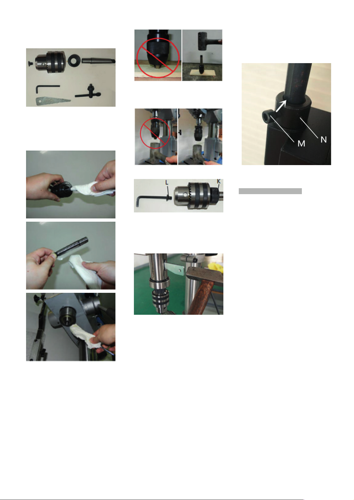
6.5 Tool installation and
Note: make sure the bolt (M) aligning
otherwise the Interlock switch would
the machine. Before connecting the
check the power spec. to avoid any
If the machine is not used for a long
Never put the power cable near the
The head assembly must be locked
Before drilling, release the quill lock
DO NOT start to drill the work piece
Uninstallation
1. Clean the drill chuck, arbor and
spindle taper thoroughly before
installation. Any insufficient
cleaning on mating surfaces may
cause drill loosen as operating and
unsafe conditions.
3. Slide the assembled drill chuck and
arbor into spindle taper, and slightly
hit them by rubber hammer to fit in.
4. Sequentially tighten”K” and ”L”
to the groove (aimed by the arrow),
not be triggered when the shields
being opened.
7. Operating Precautions
2. Place a thin wood plank on the
worktable to protect the surface of
the worktable and chuck drill. Draw
back the chuck nose into chuck
body and slightly hit the arbor onto
the chuck by rubber hammer.
The following operating and safety
precautions must be observed in order
5. Lower the spindle about 100 mm.
6. Place the drift key into the aperture
of the quill and tap the end of the
drift key with a hammer until the bit
or chuck arbor falls down.
6.6 The Spindle Shield
This clear plastic shield should be used
whenever conducting a drilling or
tapping operation. Clean the safety
guard periodically to provide a clear
view of the work piece. Adjustments can
be done as follows.
1. Adjust the internal cover shield to
have better range protection.
2. If both internal and external shields
cannot provide enough protection,
loosen locking bolt (M) to shift
setting ring (N) in proper position.
to avoid harm to the operator or
damage to the drill press.
1. Make sure the power voltage is for
plug to socket, it is necessary to
damage occurring.
2.
time, the plug should be
disconnected.
3.
fire or water environment, to break
or press the power cable is not
allowed.
4.
to the column so the thrust
produced by drilling will not force
the head assembly up the column.
5. The work table must be locked to
the column so it will not be forced
down the column.
6.
nut to permit free travel of the quill.
7. Be sure the belt is tightened to the
proper tension.
8.
until making certain the work piece
is held down securely.
8
Page 9

9. Make sure the power being off
when changing the belt for shifting
speed.
10. Point of operation protection is
required for maximum safety. This
remains the responsibility of the
user/purchaser since conditions
differ between jobs.
11. Make sure the drill is secured in the
spindle or chuck before attempting
to use the drill press.
12. Make sure the spindle taper is
clean and free of burrs, scoring,
and galling to assure maximum
gripping.
13. Lock the quill in position when
using any side-loaded tool.
8. Maintenance
Lubrication and Routine Maintenance
Apply oils to the driving parts of the
machine prior to operation and supply
coolant during operation to ensure
stability of cutters and the object being
processed. Please refer to the
lubrication as below for more details
about use oil. To extend your machine
life, please make a maintenance
schedule daily, weekly, monthly or
semi-annual and annual. Neglecting the
machine maintenance will result in
premature wear and poor performance.
1. Lubrication
I. Lubricate - Column, Quill. Use
machine tool oil with light film
of oil.
II. Grease - Rack on the column
so that the worktable can
move up/down smoothly. Use
SAE 20 oil. To clean rack with
kerosene before applying oil.
2. Daily Maintenance
Make a general cleaning by
removing dust and shavings from
the machine.
Check that the shields and
emergency stops are in good
working order.
After daily use, disconnect
machine from power source or
press emergency stop switch to
shut off the power completely. Do
not keep the machine connected
over 24 hours, it may cause
damage to the machine.
3. Weekly Maintenance
Clean the machine.
4. Monthly Maintenance
Lubricate machine column, spindle
and rack devices.
Check that all screws on the motor
and the guard are tight and
secured on the right position.
5. Annual Maintenance
Replace the driving belt by using:
530J
6. Oils for Lubricating Coolant
Considering the vast range of
products in the market, the user
can choose the one most suited to
their own requirements, using as
reference the type SHELL LUTEM
OIL ECO.
The minimum percentage of oil
diluted in water is 8~10%.
7. Oil Disposal
Oil products must be disposed in a
proper manner following local
regulations.
8. Special Maintenance
Special maintenance operations
must be carried out by skilled
personnel. However, we advise
contacting dealer and/or importer
the term special maintenance also
covers the resetting of protection
and safety equipment and devices.
9. Environmental protection
Protect the environment.
Your appliance contains valuable
materials which can be recovered or
recycled. Please leave it at a
specialized institution.
This symbol indicates separate
collection for electrical and electronic
equipment required under the WEEE
Directive (Directive 2012/19/EC) and is
effective only within the European
Union.
10. Available accessories
Refer to the Pricelist for various
accessories.
9
Page 10
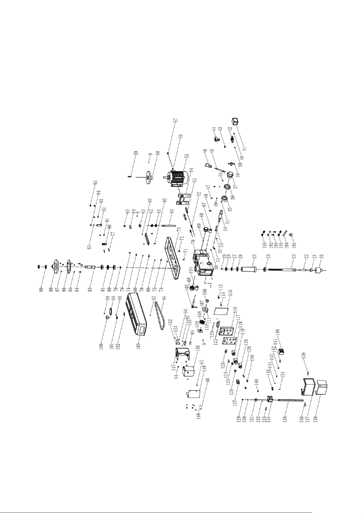
10
Page 11
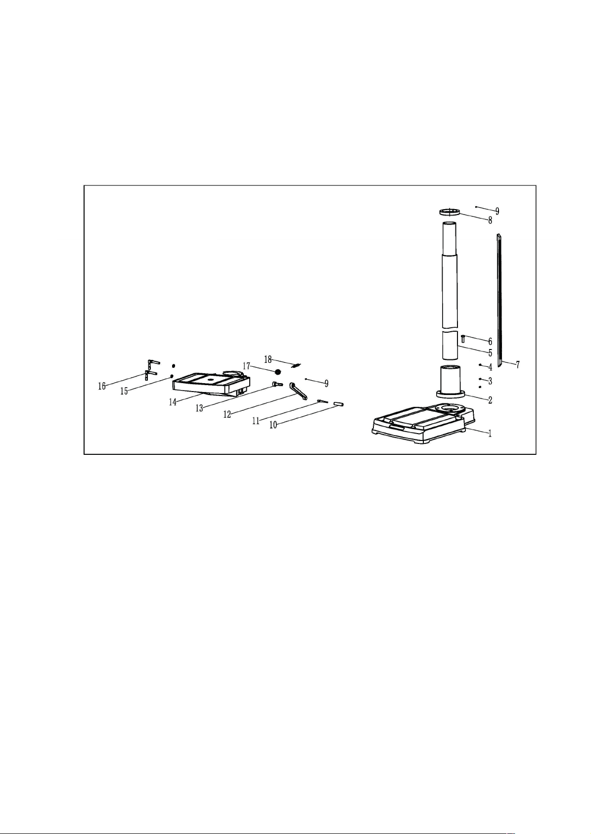
ZS1725F-VS
Assembly Breakdown
11
Page 12

Parts List for Breakdown – (1/4)
Index No. Part No. Description Qty.
1 ................. S2001001 ............................ Base ............................................................................................................. 1
2 ................. S1601002-03 ....................... Column support .......................................................................................... 1
3 ................. PIN8X30GB879.1B .............. Pin ............................................................................................................... 1
4 ................. M8X10GB80B ...................... Hexagon socket setting screws ................................................................... 2
5 ................. S1601003-03 ....................... Column(#98) .......................................................................................... 1
6 ................. M12X40GB5781B ................ Hexagon bolt ............................................................................................... 4
7 ................. S1601010 ............................ Rack ............................................................................................................. 1
8 ................. S1601011 ............................ Rack collar ................................................................................................... 1
9 ................. M6X8GB80B ........................ Hexagon socket setting screws ................................................................... 5
10 ............... 1501009-2 ........................... Crank arm handle grip ................................................................................. 1
11 ............... 1501009-3 ........................... Crank arm handle shaft ............................................................................... 1
12 ............... 1901009-1 ........................... Crank arm shaft ........................................................................................... 1
13 ............... 1901008 .............................. Worm shaft ................................................................................................. 1
14 ............... S1601014-01 ....................... Table ............................................................................................................ 1
15 ............... BRG51102GB301 ................ Thrust bearing ............................................................................................. 2
16 ............... S1401012 ............................ Bracket locking handle assembly ................................................................ 2
17 ............... 1501006 .............................. Helical gear .................................................................................................. 1
18 ............... S1601019 ............................ Gear pin ....................................................................................................... 1
20 ............... 1-16mm ZB16 ..................... Chuck ........................................................................................................... 1
21 ............... S1603004 ............................ Arbor locking nut ......................................................................................... 1
22 ............... MT2-B16-T .......................... Arbor ........................................................................................................... 1
23 ............... S1603001 ............................ Spindle .........................................................................................................
24 ............... BRG6205-2RSGB276 ........... Bearing ........................................................................................................ 1
25 ............... S1603002 ............................ Quill ............................................................................................................. 1
26 ............... 1703006 .............................. Washer ........................................................................................................ 1
27 ............... D40GB7590B ....................... Spring washer .............................................................................................. 1
28 ............... BRG6203-2RSGB276 ........... Bearing ........................................................................................................ 1
29 ............... CLP20GB894.1B .................. Shaft ring ..................................................................................................... 1
30 ............... PIN4X16GB879.1 ................. Pin ............................................................................................................... 1
31 ............... 1506003-01 ......................... Pointer ......................................................................................................... 1
32 ............... M4X8GB818B ...................... Cross pan head screw .................................................................................. 1
33 ............... S1604012 ............................ Locking bolt ................................................................................................. 1
34 ............... S1604002 ............................ Gear shaft .................................................................................................... 1
35 ............... S1604003G .......................... Collar Depth stop ........................................................................................ 1
36 ............... S1604014G .......................... Locking ring ................................................................................................. 1
37 ............... S1604001G .......................... Hub .............................................................................................................. 1
38 ............... S1604004 ............................ Fixed depth locking assembly ..................................................................... 1
39 ............... ST4.2X9.5GB845Z ................ Self-tapping screw ....................................................................................... 2
40 ............... M5X12GB973Z .................... Cross recessed oval head screw .................................................................. 2
41 ............... S2002013 ............................ Travel switch cover ..................................................................................... 1
42 ............... S2002012 ............................ Travel switch base ....................................................................................... 1
43 ............... S1609030 ............................ Protective rubber sleeve ............................................................................. 1
44 ............... YBLXW-5/11Q1 ................... Travel switch ............................................................................................... 2
45 ............... S1604005G .......................... Handle ......................................................................................................... 3
46 ............... 1504011-03 ......................... Ball knob ...................................................................................................... 3
47 ...............
48 ............... PIN8X35GB879.1B .............. Pin ............................................................................................................... 1
49 ............... S1609031 ............................ O Ring .......................................................................................................... 1
50 ............... M5X6GB80B ........................ Hexagon socket set screw ........................................................................... 1
51 ............... PIN4X16GB119.1B .............. Cylinder pin ................................................................................................. 1
52 ............... M10X35GB5781B ................ Hexagon bolt ............................................................................................... 2
53 ............... S1602003 ............................ Motor rod .................................................................................................... 2
S1607005 ............................ Depth pin ..................................................................................................... 2
1
12
Page 13

Parts List for Breakdown – (2/4)
Index No. Part No. Description Qty.
54 ............... S1602007 ............................ Motor base .................................................................................................. 1
55 ............... T-0.55-380/220-80-6P ........ Motor .......................................................................................................... 1
56 ............... WSH8GB97.1B .................... Washer ........................................................................................................ 4
57 ............... M8X30GB5781B .................. Hexagon bolt ............................................................................................... 4
58 ............... S1605005-01 ....................... Motor pulley ............................................................................................... 1
59 ............... PIN8x7x45GB1096 .............. Pin ............................................................................................................... 1
60 ............... S1607002 ............................ Rod .............................................................................................................. 1
61 ............... S1609010 ............................ Cramp .......................................................................................................... 2
62 ............... 110W 400Ω ........................ Resistance ................................................................................................... 1
63 ............... S1606014 ............................ Magnetic switch base ................................................................................. 1
64 ............... LJC1-3/24 ............................ Magnetic switch ......................................................................................... 1
65 ............... M4X16GB818B .................... Cross pan head screw .................................................................................. 8
66 ............... M5GB6170B ........................ Nut .............................................................................................................. 6
67 ............... S1602005 ............................ Right clamp block ........................................................................................ 1
68 ............... S1609007 ............................ Motor locking button .................................................................................. 2
69 ............... M6X10GB80B ...................... Hexagon socket set screw ........................................................................... 1
70 ............... S1602001-VS ....................... Headstock .................................................................................................... 1
71 ............... M5X16GB973Z .................... Cross recessed oval head screw .................................................................. 4
72 ............... 0805009 .............................. Foam pad .................................................................................................... 6
73 ............... S1605002-01 ....................... Cover ........................................................................................................... 1
74 ............... 1905010 .............................. Line protecting ............................................................................................ 4
75 ............... 1502014 .............................. Cable clamp ................................................................................................. 3
76 ............... 1502014
77 ............... M3X14GB818B .................... Cross recess pan head screw ....................................................................... 2
78 ............... M5X12GB9074D1Z ............. Cross pan head with cushion screw ............................................................ 6
79 ............... CLP30GB894.1B .................. Shaft ring ..................................................................................................... 1
80 ............... BRG6205-2RSGB276 ........... Bearing ........................................................................................................ 2
81 ............... S1602023 ............................ bearing spacer ............................................................................................. 1
82 ............... WSH4GB93B ....................... Spring washer .............................................................................................. 1
83 ............... S1602022 ............................ Splined ......................................................................................................... 1
84 ............... M6X16GB973Z .................... Cross recessed oval head screw .................................................................. 3
85 ............... WSH6GB93B ....................... Spring washer .............................................................................................. 3
86 ............... S1604015 ............................ Digital display chuck .................................................................................... 1
87 ............... 1009005 .............................. Padding block .............................................................................................. 3
88 ............... S1605009-01 ....................... Spindle pulley .............................................................................................. 1
89 ............... M24X1.5GB810B ................. Small round nut ........................................................................................... 2
90 ............... CB07-5L ............................... Sensor ......................................................................................................... 1
91 ............... 1308004 .............................. Heighten block ............................................................................................ 2
92 ............... 1304019 .............................. Speed measuring base ................................................................................ 1
93 ............... WSH3GB97.1B .................... Washer ........................................................................................................ 2
94 ............... M4X12GB973Z .................... Cross recessed oval head screw .................................................................. 1
95 ............... M3GB6170Z ........................ Nut .............................................................................................................. 2
96 ............... 460J ..................................... Poly V belt ................................................................................................... 1
97 ............... M4GB6170Z ........................ Nut .............................................................................................................. 6
98 ............... M4X12GB973Z .................... Cross recessed oval head screw .................................................................. 4
99 ............... S1605003 ............................ Cover plate .................................................................................................. 1
100 .............
101 ............. WSH12GB96.1B .................. Washer ........................................................................................................ 1
102 ............. S1605004 ............................ Hinge ........................................................................................................... 1
103 ............. S1605001 ............................ Cover ........................................................................................................... 1
104 ............. S1602004 ............................ Left clamp block .......................................................................................... 1
105 ............. S1602015 ............................ Headstock locking handle assembly ............................................................ 1
106 ............. S1604006 ............................ Supporting sleeve ........................................................................................ 1
107 ............. S1604008-01 ....................... Spring cover ................................................................................................ 1
108 ............. S1604009 ............................ Coil spring .................................................................................................... 1
109 ............. S1604007-01 ....................... Spring cover ................................................................................................ 1
S1605008 ............................ Round handle .............................................................................................. 1
-02 ......................... Cable clamp ................................................................................................. 3
13
Page 14

Parts List for Breakdown – (3/4)
Index No. Part No. Description Qty.
110 ............. M5X12GB973Z .................... Cross recessed oval head screw .................................................................. 3
111 ............. PIN6X10GB879.1 ................. Pin ............................................................................................................... 1
113 ............. M8GB6172B ........................ Thin nut ....................................................................................................... 1
114 ............. M8X16YJT4023B ................. Hex socket bead set screw .......................................................................... 1
115 ............. S1602011 ............................ Insulation paper .......................................................................................... 1
116 ............. S1602008-03 ....................... Switch panel (gray) ...................................................................................... 1
117 ............. S1606101-03 ....................... Switch position plate ................................................................................... 1
118 ............. LA115-A5-100BN ................ Start switch (double row) ............................................................................ 1
119 ............. LA115-A5-01ZS .................... Emergency stop switch ............................................................................... 1
120 ............. LA115-A5-01BN ................... Stop switch .................................................................................................. 1
121 ............. ST2.2X4.5GB845 ................. Self-tapping screw ....................................................................................... 2
122 ............. CB07-12B ............................ Digital readout ............................................................................................ 1
123 ............. K16-211 ............................... Button switch .............................................................................................. 1
124 ............. M5X40GB973Z .................... Cross recessed oval head screw .................................................................. 4
125 ............. B103-Y ................................. Potentiometer (cylinder) ............................................................................. 1
126 ............. B103-M ............................... Potentiometer cap ...................................................................................... 1
127 ............. LW26-10 .............................. Transfer switch ............................................................................................ 1
128 ............. ZSD24VDC-G ....................... Indicator green DC ...................................................................................... 1
129 ............. M6X12GB70.1B ................... hexagon socket cap screws ......................................................................... 1
130 ............. WSH6GB96.1B .................... Wasjer ......................................................................................................... 1
131 ............. S1607003 ............................ Chuck guard lock knob ............................................................................... 1
132 ............. PIN3X10GB879.1B .............. Pin ............................................................................................................... 1
133 ............. M6x35GB70D1B .................. hexagon socket cap screws ......................................................................... 4
134 ............. S1609004 ............................ Chuck guard micro switch base ................................................................... 1
135 ............. S1607004 ............................ Chuck guard rod .......................................................................................... 1
136 ............. 1509006 .............................. Chuck guard lock bolt .................................................................................. 2
137 ............. S1609000 ............................ External Chuck guard .................................................................................. 1
138 ............. S1609000-01 ....................... Internal Chuck guard ................................................................................... 1
139 ............. M6X40GB819.1Z ................. Cross countersunk screw ............................................................................ 4
140 ............. S1609005 ............................ Padding block .............................................................................................. 1
141 ............. M8X20GB70.1B ................... hexagon socket cap screws ......................................................................... 2
142 ............. M10X8GB8B ........................ Hexagon socket setting screws ................................................................... 2
143 ............. Φ1x6x15.75GB2089B ......... Spring .......................................................................................................... 2
144 ............. Φ8GB17445 ....................... Steel ball ...................................................................................................... 2
145 ............. KW7-03B ............................. Micro switch ................................................................................................ 1
146 ............. M6X12GB70.1B ................... hexagon socket cap screws ......................................................................... 1
147 ............. S1604016 ............................ Frequency converter base ........................................................................... 1
148 ............. WSH5GB93B ....................... Spring washer .............................................................................................. 4
149 ............. S1604017 ............................ Frequency converter cover ......................................................................... 1
150 ............. LSD-C7400-0.75KW ............. Frequency converter ................................................................................... 1
151 ............. B26-7B ................................ Transformer ................................................................................................ 1
152 ............. F11A-E 11P .......................... Relay base ................................................................................................... 1
153 ............. YJ3N-GS 24VDC ................... Relay ............................................................................................................ 1
154 ............. M3X14GB818Z .................... Cross pan head screw .................................................................................. 2
155 ............. S1601001 ............................ Base ............................................................................................................. 1
156 ............. S1601003-01A/B .................
157 ............. S1601023 ............................ Cone gear shaft ........................................................................................... 1
158 ............. BRG51102GB301 ................ Thrust bearing ............................................................................................. 1
159 ............. S1601012 ............................ Cover ........................................................................................................... 1
160 ............. M5X12GB70.1B ................... Hexagon socket cap screws ......................................................................... 4
161 ............. M6X6GB80B ........................ Hexagon socket set screw ........................................................................... 1
162 ............. S1601009 ............................ Crank arm handle assembly ........................................................................ 1
163 ............. CLP15GB894.1B .................. C-clip ........................................................................................................... 1
164 ............. φ6JB7940D4 ...................... Oil cup ......................................................................................................... 1
165 ............. M4X12GB819D1Z ............... Cross countersunk head screw ................................................................... 4
166 ............. S1607001 ............................ Cover ........................................................................................................... 1
Column ........................................................................................................ 1
14
Page 15

Parts List for Breakdown – (4/4)
Index No. Part No. Description Qty.
167 ............. S1607006 ............................ Lead screw shaft sleeve .............................................................................. 1
168 ............. BRG51102GB301 ................ Thrust bearing ............................................................................................. 1
169 ............. PIN6GB117 .......................... Pin ............................................................................................................... 1
170 ............. CLP20GB894.1B .................. C-clip ........................................................................................................... 1
171 ............. S1601005 ............................ Cone gear .................................................................................................... 1
172 ............. BRG6204-2RSGB276 ........... Bearing ........................................................................................................ 1
173 ............. S1601006 ............................ Lead screw .................................................................................................. 1
174 ............. S1601015 ............................ Nut .............................................................................................................. 1
175 ............. S1601011-01 ....................... Rack collar ................................................................................................... 1
176 ............. M12X60GB70.1B ................. Hexagon socket cap screws ......................................................................... 1
177 ............. M16GB6170B ...................... Nut .............................................................................................................. 1
178 ............. WSH16GB97D1Z ................. Washer ........................................................................................................ 1
179 ............. S1601016 ............................ Double end bolt .......................................................................................... 1
180 ............. M12GB6177.1B ................... Nut .............................................................................................................. 1
181 ............. WSH12GB96.1Z ................... Washer ........................................................................................................ 1
182 ............. M12X60GB35Z .................... Bolt .............................................................................................................. 1
183 ............. S1601014 ............................ Table ............................................................................................................ 1
184 ............. S1601004 ............................ Table support .............................................................................................. 1
185 ............. S1401012 ............................ Column lock handle ..................................................................................... 1
186 ............. RDV2D2.5GB12618D1 ......... Rivet ............................................................................................................ 1
187 ............. S1606001 ............................ Tilt scale ...................................................................................................... 1
188 ............. WSH12GB97.1B .................. Washer ........................................................................................................ 1
189 ............. M12X40GB5781B ................ Hexagon bolt ................................................................
190 ............. YL12S-C11GZ ....................... Self - locking button .................................................................................... 2
191 ............. 0402205 .............................. Laser light fixing base .................................................................................. 4
192 ............. 0402204 .............................. Laser light locking ring ................................................................................ 2
193 ............. JGD-DC3V ............................ Laser light .................................................................................................... 2
194 ............. M3X16GB818Z .................... Cross pan head screw .................................................................................. 4
195 ............. 1309050 .............................. LED light ...................................................................................................... 1
............................... 1
15
Page 16
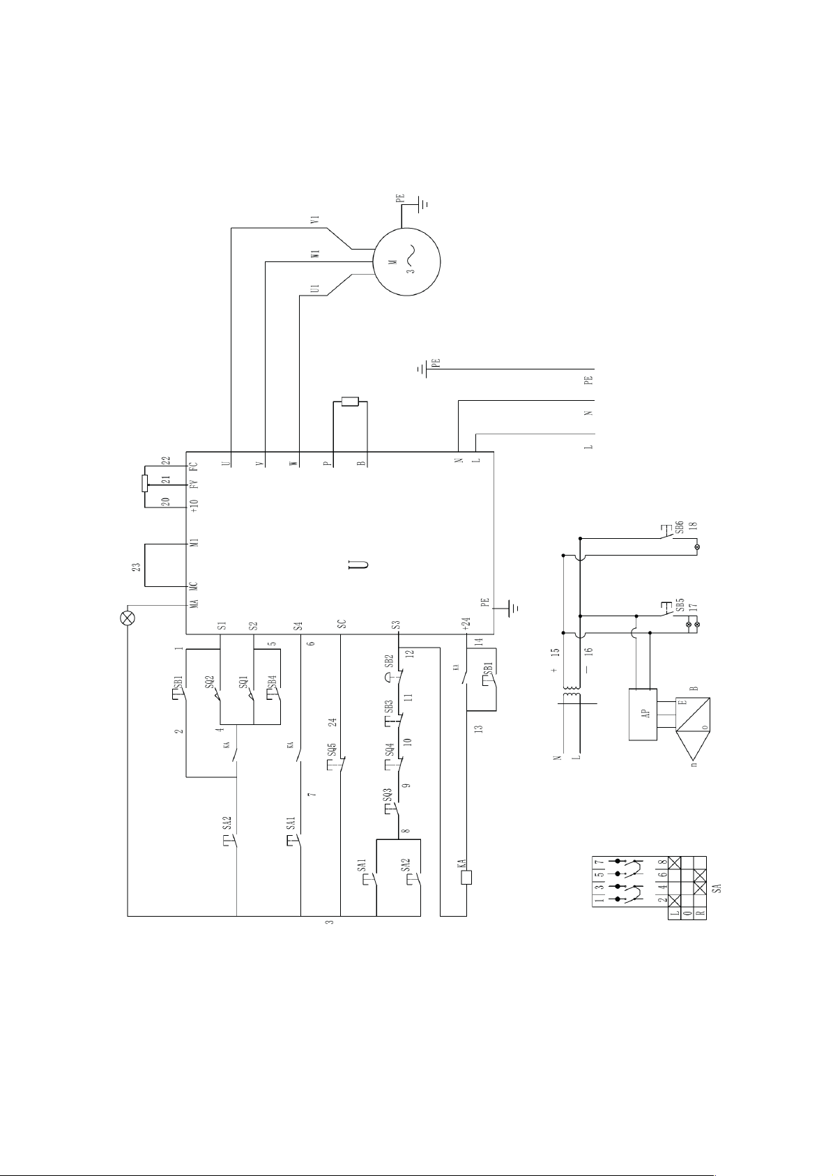
Wiring Diagram
220V&110V with Foot pedal switch
16
Page 17
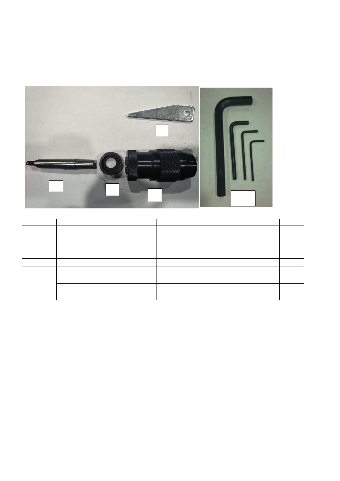
Index
Description
Size
Qty.
Arbor(B16-MT2)
B/F
1
B/F
2
Nut
B/F
1
3
Chuck
B/F
1
4
Slant Wedge
B/F
1
B/F
B/F
L Hex Wrench 5 mm
B/F
1
L Hex Wrench 10mm
B
1
1
2
3
4
5
1
5
Arbor(B16-MT2)
L Hex Wrench 3 mm
L Hex Wrench 4 mm
1
1
1
171819
Page 18

Page 19

Page 20
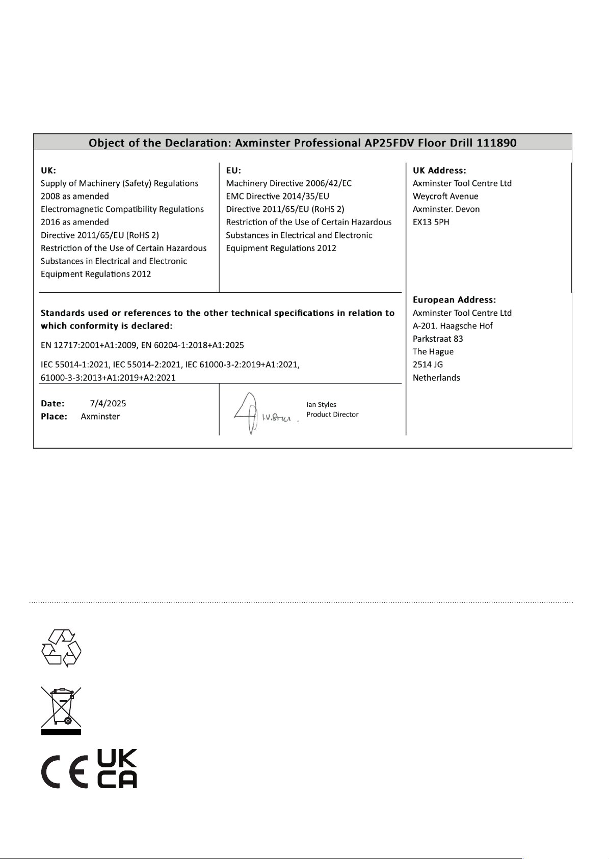
The packaging is suitable for recycling.
Please dispose of it in a responsible manner.
EU Countries Only
Do not dispose of electric tools together with household waste material.
By law they must be collected and recycled separately.
Axminster Tools, Axminster Devon EX13 5PH
axminstertools.com
 Loading...