

Page 1
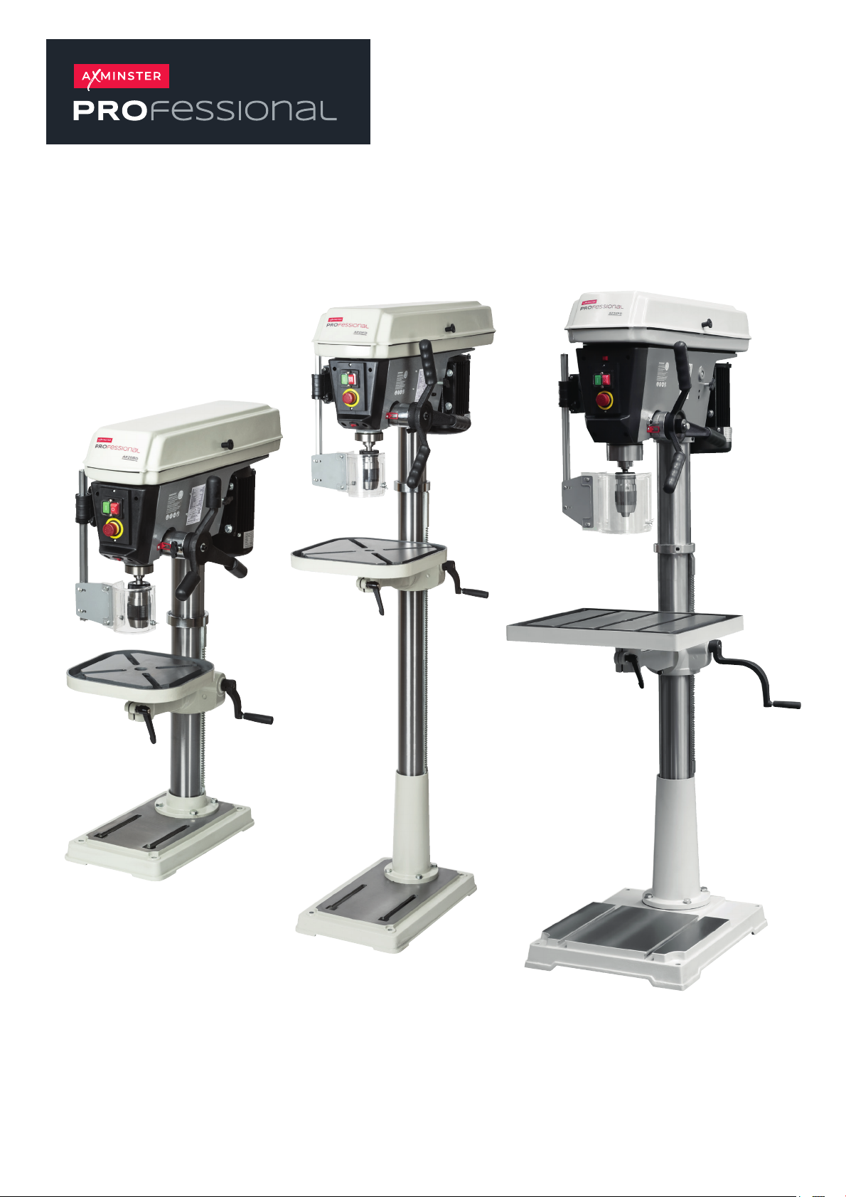
Bench & Floor Drills
User manual
AP20BD Code: 111891
AP25FD Code: 111892
AP32FD Code: 111893
AP20BD
Code: 111891
AP25FD
Code: 111892
AP32FD
Code: 111893
AT: 27/8/2025
BOOK VERSION: 2
Page 2
INDEX OF CONTENTS
What’s Included 03
General Safety Instructions 05
General Safety Instructions for Drilling Machines 06
Specication 07
Assembly 08
Illustration and Parts Description 14
Changing the Speed 18
Levelling the Table AP32FD Only) 18
Tilting the Table 19
Removing the Keyless Chuck 19
Maintenance 20
Speed Select Tables 21
Drill Speed Material Table 22
Troubleshooting 23
Exploded Diagram/Parts List 24
Wiring Diagram 28
Declaration of Conformity 29
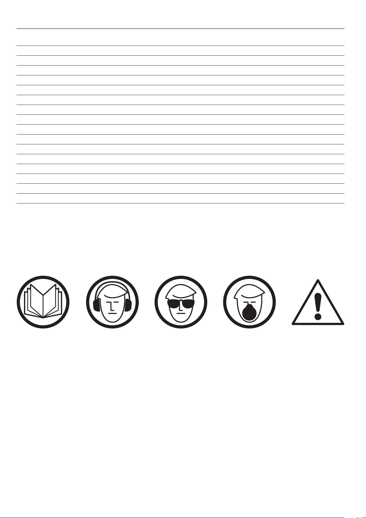
The symbols below advise the correct safety procedures when using this machine.
Fully read manual
and safety instructions
before use
Ear protection
should be worn
Eye protection
should be worn
Dust mask
should be worn
HAZARD
2
Page 3
WHAT’S INCLUDED
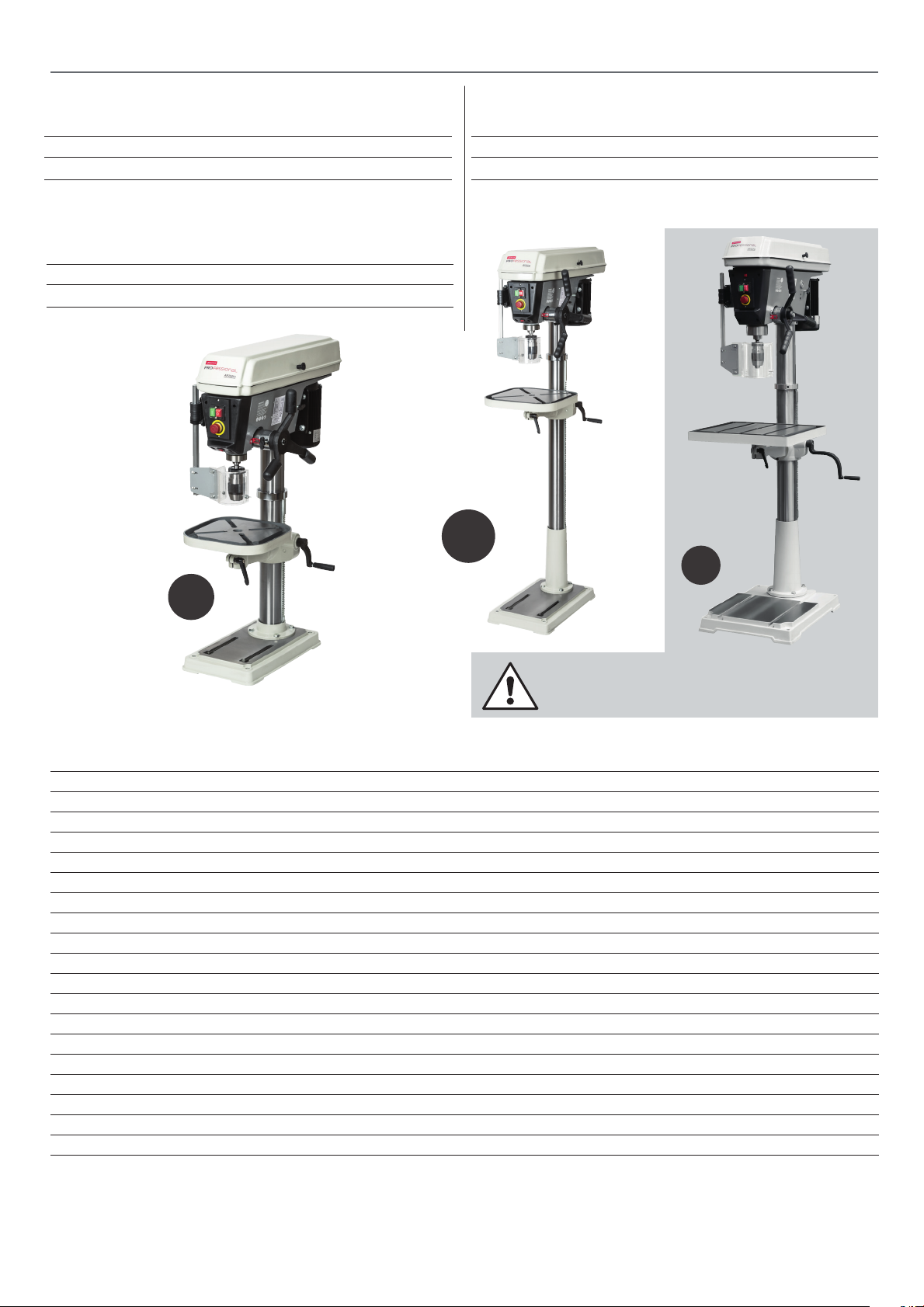
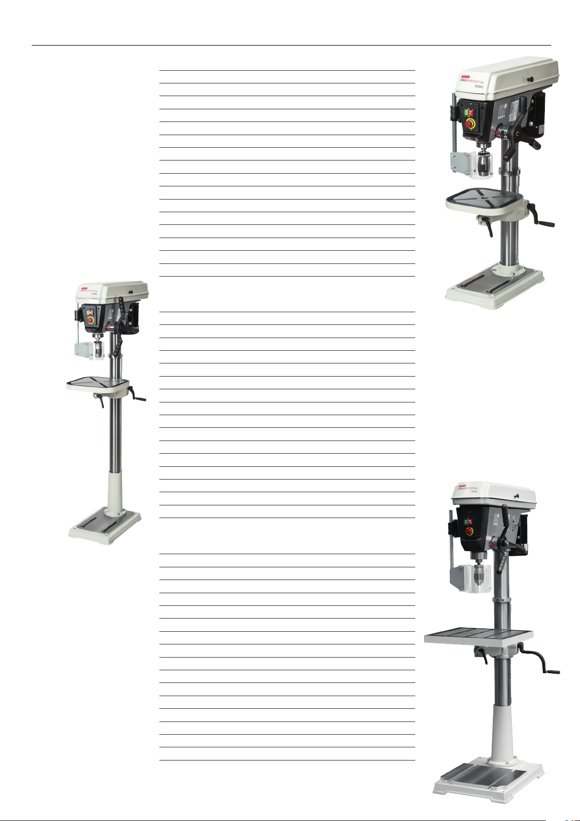
Model Number AP20BD Model Number AP32FD
Quantity Item Part
1 No Bench Pillar Drill (ZQJ4119K) A
Model Number AP25FD
Quantity Item Part
1 No Floor Pillar Drill B
Quantity Item Part
1 No Floor Pillar Drill C
B
C
A
THE AP32FD IS EXTREMELY HEAVY & COMES
LARGELY ASSEMBLED FOR SAFETY AND
TRANSPORT!
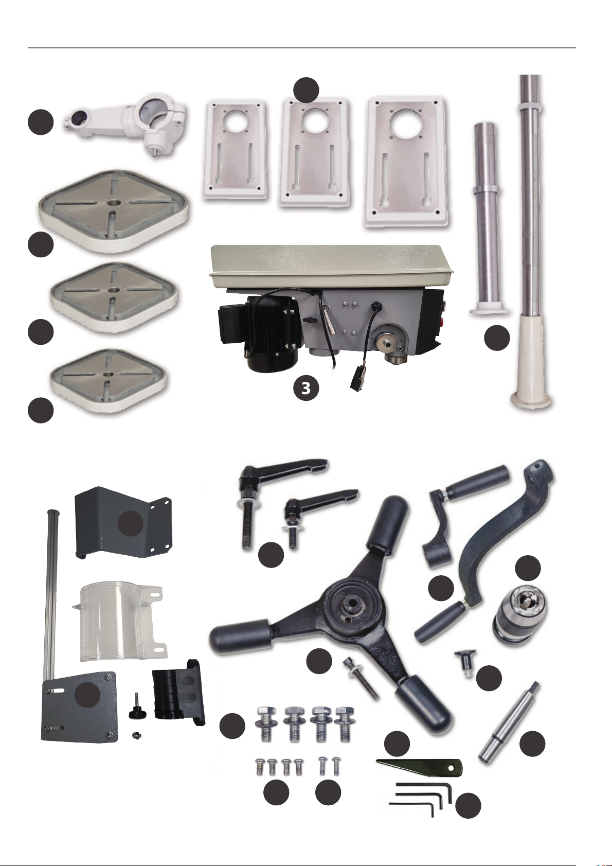
Box Containing:
1 Pillar for drill head complete with mounting
ange, rise and fall rack and retaining ring 1
1 Drill table extension bracket arm 2
1 Pillar drill head 3
1 Drill table square (Medium) 4a (111891 ONLY)
1 Drill table square (Large) 4b (111892 ONLY)
1 Base (Small,Medium, Large) 5 (111891, 111892 ONLY)
1 Chuck guard assembly mounting bracket 6
1 Chuck guard assembly 7
2 Lift and shift handle clamps for the rise and fall mechanism, drill table 8
1 Lever feed handle assembly with M8x50mm cap head screw 9
1 Crank handle for table rise and fall mechanism (small) 10 (111891, 111892 ONLY)
1 Crank handle for table rise and fall mechanism (Large) 10 (111893 ONLY)
1 Keyless chuck 3-16mm 11
1 Morse taper arbor for chuck assembly 12
1 Pulley cover knob & Phillips screw 13
1 Morse taper drift 14
3 Hex Keys 3-5-6mm 15
4 M10x25mm + washers 16 (111891, 111892 ONLY)
4 M6x11mm Button head Phillips screws 17
2 M5x14mm Button head Phillips screws 18
3
Page 4
WHAT’S INCLUDED
2
4b
5
4a
4
1
3
6
8
11
10
7
16
9
17 18
4
14
13
12
15
Page 5

GENERAL SAFETY INSTRUCTIONS
The following will enable you to observe good working
practices, keep yourself and fellow workers safe and maintain
your tools and equipment in good working order.
WARNING!! KEEP TOOLS AND EQUIPMENT
OUT OF REACH OF YOUNG CHILDREN
KEEP WORK AREA AS UNCLUTTERED AS IS
PRACTICAL. UNDER NO CIRCUMSTANCES SHOULD
CHILDREN BE ALLOWED IN WORK AREAS.
Mains Powered Tools
• Tools are supplied with an attached 13 Amp plug.
• Inspect the cable and plug to ensure that neither are
damaged. Repair if necessary by a suitably qualied person.
• Do not use when or where it is liable to get wet.
Workplace
• Do not use 230V a.c. powered tools anywhere
within a site area that is ooded.
• Keep machine clean.
• Leave machine unplugged until work is about to commence.
• Always disconnect by pulling on the plug body and not the
cable.
• Carry out a nal check e.g. check the cutting tool
is securely tightened in the machine and the correct
speed and function set.
• Ensure you are comfortable before you start work,
balanced, not reaching etc.
• Wear appropriate safety clothing, goggles, gloves,
masks etc. Wear ear defenders at all times.
• If you have long hair wear a hair net or helmet to prevent it
being caught up in the rotating parts of the machine.
• Consideration should be given to the removal of rings and
wristwatches.
• Consideration should also be given to non-slip footwear etc.
• If another person is to use the machine, ensure they are
suitably qualied to use it.
• Do not use the machine if you are tired or distracted
• Do not use this machine within the designated safety areas
of ammable liquid stores or in areas where there may be
volatile gases.
• Check cutters are correct type and size, are undamaged
and are kept clean and sharp, this will maintain their
operating performance and lessen the loading on the
machine.
• OBSERVE…. make sure you know what is happening
around you and USE YOUR COMMON SENSE.
5
Page 6

GENERAL SAFETY INSTRUCTIONS FOR DRILLING MACHINES
1. DO NOT operate the machine without carrying out
a preliminary inspection.
2. CHECK that the speed is correct for the planned operation,
and the upper drive belt cover is closed and fastened secure.
3. CHECK the drill bit is the correct size and type, is correctly
tted and tightened in the chuck.
4. Make sure that the drill head, the table bracket arm, the table
tilt and the table swivel clamps are all locked before any drilling
is attempted.
5. DO NOT attempt to carry out any drilling operation on
material that has not been secured to the drill table, either by
vice or clamp.
6. Remove any tools (chuck key, spanners etc), that may have
been used in setting up operations and put them away in their
correct stowage positions.
7. Try to arrange the drilling operation so that the drill tip does
not come in contact with the table.
8. ALWAYS allow the drill to stop before removing drills or
swarf from around the job or the table.
9. NEVER remove ‘ying’ swarf strands from the drill whilst it is
turning.
10. It is a good precaution to wear eye protection when drilling,
especially using small drills, or very hard material that produces
small chips.
11. It is not a good idea to wear gloves when operating a drill
press.
12. After the job is completed, remove all tools and accessories
from the machine, check that drill bits are still sharp and re-use
able.
13. Clean the machine down thoroughly, including removing
coolant or cutting compounds from the drill table.
14. Lightly coat all metal surfaces with a light oil coating.
15. Disconnect the machine from the supply. Secure the cable/
plug clear of the oor.
6
Page 7
AP25FD
Code: 111892
Code 111891
Model AP20BD
Rating Professional
Power 750W (230V 1ph)
Speed Range (12) 120-2,580rpm
Throat 178 mm
Taper 2MT
Chuck Cap/Type 1-16mm keyless
Chuck Travel 80 mm
Max Chuck to Table 325 mm
Max Chuck to Base 500 mm
Diameter of Column 80 mm
Table Size 290 x 290 mm
Table Tilt 45˚ - 0 - 45˚
Base Size 450 x 270 mm
Overall Size L x W x H 670 x 360 x 1,020 mm
Weight 82 kg
Code 111892
Model AP25FD
Rating Professional
Power 750W (230V 1ph)
Speed Range (12) 120-2,580rpm
Throat 216 mm
Taper 3MT/B16
Chuck Cap/Type 1-16mm keyless
Chuck Travel 80 mm
Max Chuck to Table 700 mm
Max Chuck to Base 1,150 mm
Diameter of Column 80 mm
Table Size 345 x 345 mm
Table Tilt 45˚ - 0 - 45˚
Base Size 520 x 320 mm
Overall Size L x W x H 750 x 430 x 1,650 mm
Weight 92 kg
SPECIFICATION
AP20BD
Code: 111891
Code 111893
Model AP32FD
Rating Professional
Power 1100W (230V 1ph)
Speed Range (12) 150-2,700rpm
Throat 254 mm
Taper 3MT
Chuck Cap/Type 3-16mm keyless
Chuck Travel 120 mm
Max Chuck to Table 540 mm
Max Chuck to Base 1,090 mm
Diameter of Column 92 mm
Table Size 475 x 425 mm
Table Tilt 45˚ - 0 - 45˚
Base Size 580 x 450 mm
Overall Size L x W x H 860 x 610 x 1,710 mm
Weight 143 kg
7
AP32FD
Code: 111893
Page 8
ASSEMBLY
Having unpacked your machine and its accessories, please
check the contents against the equipment list ”What’s Included”, if there are any discrepancies, please contact Axminster
Tools using the procedures laid down on our website.
PLEASE DISPOSE OF THE PACKAGING
RESPONSIBLY; MUCH OF THE MATERIAL
IS RECYCLABLE
The machine and its accessories will arrive coated with heavy
corrosion preventative grease and greased wax paper or plastic
wrapping. These will need to be cleaned from the machine, its
components and accessories prior to it being set up and
commissioned. Use water soluble de greaser to remove the
barrier grease. Be warned, it will stain if you splash it on
clothing etc. After cleaning, lightly coat the exposed metal
surfaces of the machine with a thin layer of light machine oil.
N.B If you used water soluble de greaser make sure you apply
this thin lm sooner rather than later.
WARNING! WEAR OVERALLS, RUBBER
GLOVES AND EYE PROTECTION!
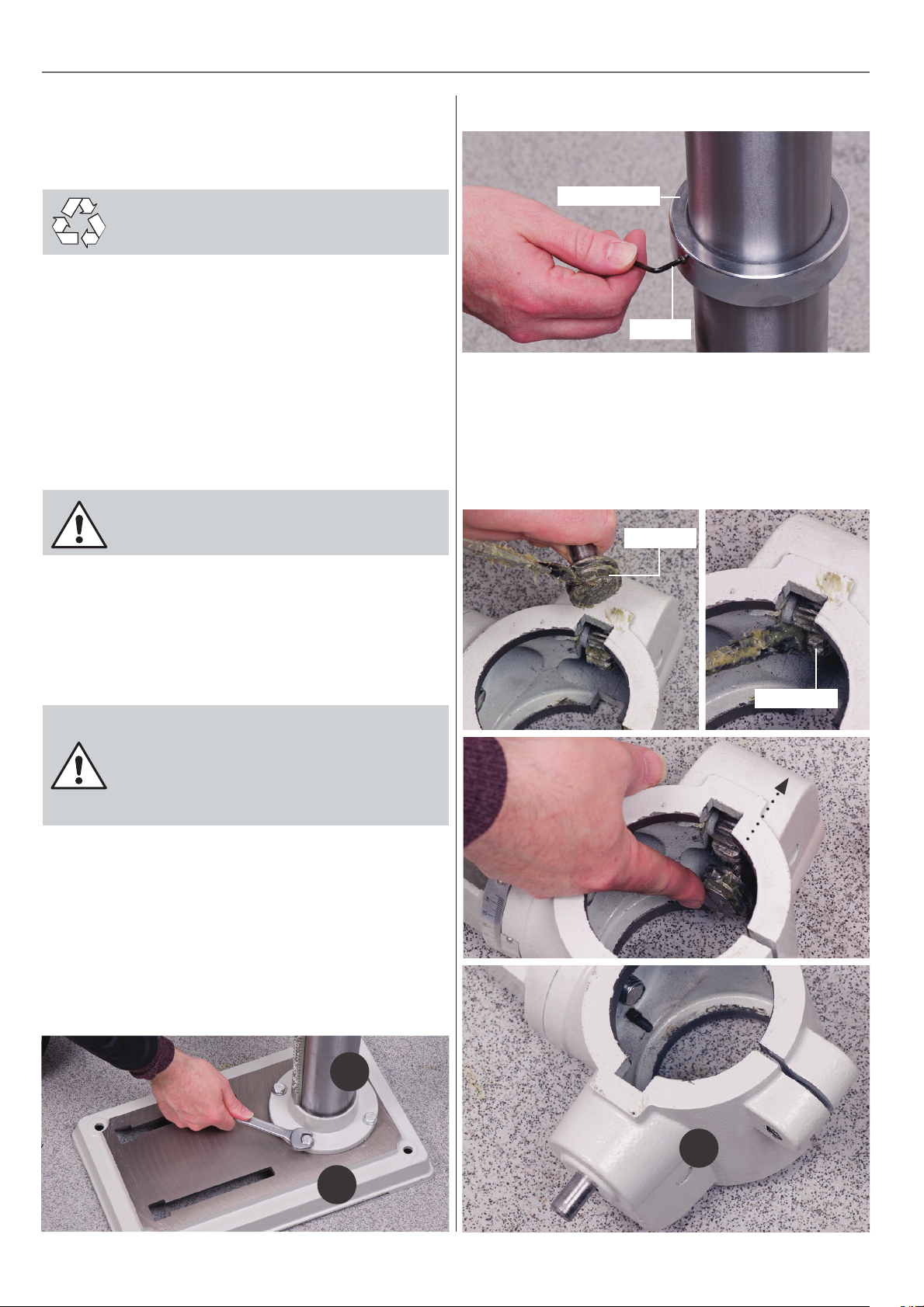
Fig 02
Retaining collar
Hex key
2. Locate the drill table mounting bracket arm (2), apply some
greese to the worm and pinion gears then twist the worm drive
shaft with your ngers so that the whole shaft protrudes from
the casting and the worm gear itself is clear of the square recess
in the main body of the casting, see g 03-04-05.
Fig 03-04-05
Worm gear
Please read the Instruction Manual prior to using your new
machine; as well as the installation procedure, there are
daily and periodic maintenance recommendations to help
you keep your machine on top line and prolong its life.
Keep this instruction manual readily accessible for any
others who may also be required to use the machine.
WARNING! THE DRILL HEAD IS A
HEAVY AND SUBSTANTIAL PIECE OF
MACHINERY, YOU ARE ADVISED TO HAVE
HELP TO LIFT IT CLEAR OF THE BOX AND
FIT IT TO THE COLUMN.
1. Place the base (5) on the bench or oor and place the
mounting ange of the column (1) onto the seating ange of
the base (5), align the holes. Use the four Hex bolts (16) and
secure the column to the base, see g 01. Loosen the grub
screw holding the chamfered retaining collar on the column
with the supplied Hex key, place it and the rise and fall rack
assembly aside, see g 02.
Fig 01
Pinion gear
5
1
2
8
Page 9
ASSEMBLY
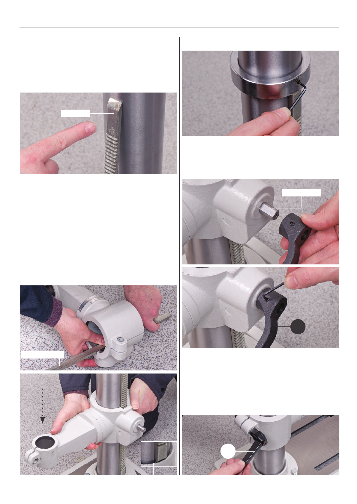
3. Pick up the rise and fall gear rack, identify the top and the
bottom, (the rack gearing is cut asymmetrically, with the gear
cut extending closer to the bottom), make sure you have the
rack the right way up, as it will allow you to drive the drill table
up and down over its full range, see g 06.
Fig 06
Top of rack
4. Fit the rise and fall rack into the square recess in the
mounting bracket arm (2) casting, ensure that it is engaged
with the pinion, see g 07. Lower the combined mechanism
over the column. Allow it to slide down the column until the
rise and fall rack is located in the cup chamfer in the top of
the mounting ange, see g 08. Replace the cup chamfered
retaining collar over the column and slide it down onto the top
of the rack. Lock it in place with the grub screw, ensuring that
it has captured the upper end of the rack securely, but not too
tight that the rack cannot be swivelled around the pillar see
g 09.
Fig 09
5. Locate and t the crank handle (10) to the shaft, ensuring
that you tighten the grub screw onto the machined at on the
shaft, this will keep the worm gear in position, see g 10-11.
Fig 10-11
Machined at
Fig 07-08
Rise and fall rack
10
6. Check that the mounting bracket can be driven up and down
the column and can swivel around the pillar. Locate the lift and
shift handle (8) and screw it into the threaded hole to the rear
of the mounting bracket arm and tighten, see g 12. DO NOT
OVERTIGHTEN as the cast iron arm could break. Check it has
‘pinched’ up on the column and the bracket is immobile; both
in its up and down travel and swivel movement.
Fig 12
Cup chamfer
8
9
Continues Over....
Page 10
ASSEMBLY
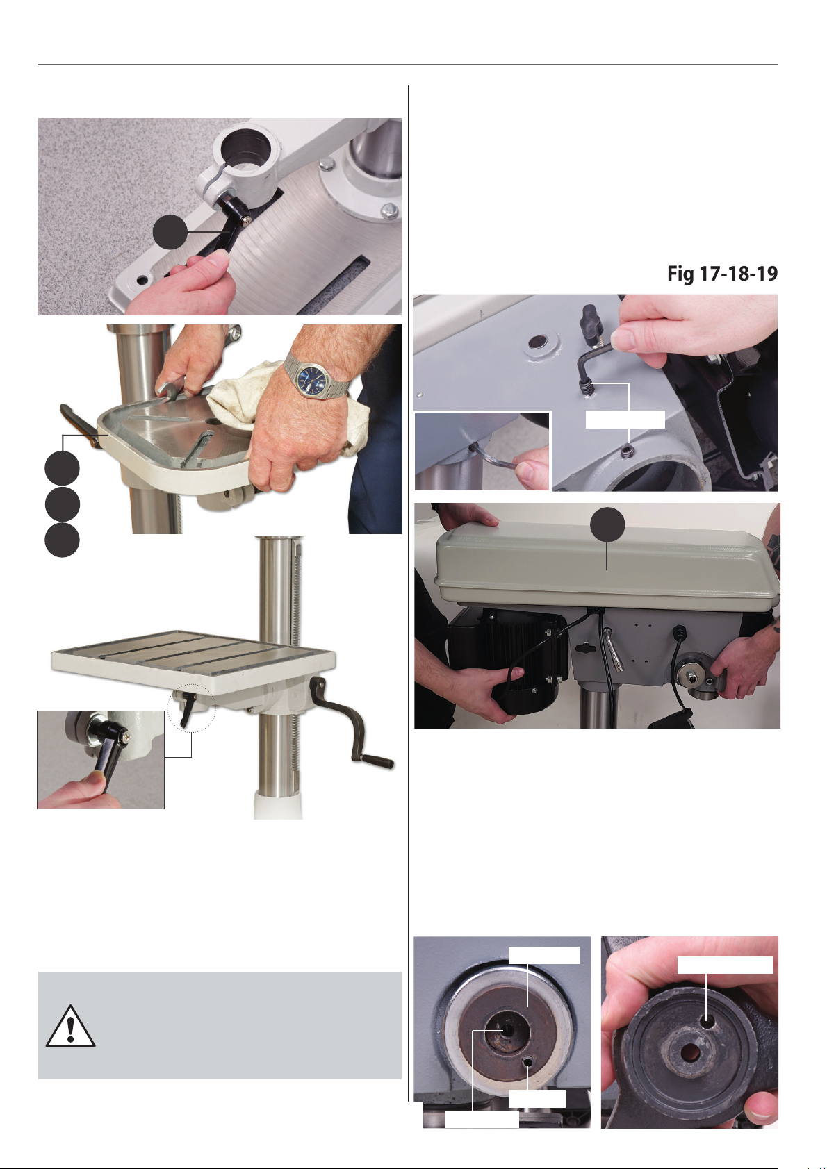
Fig 17-18-19
Fig 13-14-15
4
8
1. CHECK the drill head, ensure that the two hex socket grub
screws that lock the head in place on the column are withdrawn
and will not foul on the column when the head is tted, see
g 17. Place the assembly you have just been working on in
the designated position, make sure it is stable and lift the
drill head over the column and let it drop into place, see g 18.
Set the drill head approximately fore and aft and lock in
position using the two cap head grub screws mentioned earlier,
see g 19. Check that the drill head is immobile. Everything on
the drilling machine is now secured.
Grub screws
4a
4b
7. Screw in the remaining lift and shift handle (8) into the threaded
hole to the end of the mounting arm. DO NOT OVERTIGHTEN
as the cast iron arm could break. Lower the drill table (4,4a,4b)
spigot into the machined hole to the front of the mounting arm and
tighten the handle until it has ‘pinched’ up on the drill table’s spigot
and the table is immobile, see g 13-14-15.
3
Lever Feed Handle
2. Locate the lever feed handle and its securing cap head
bolt/washer (9), note the raised boss and spigot on feed
mechanism. Mount the handle over the boss and ensure
the spigot slots into the pre-driiled hole in the feed handle
assembly. Secure with the supplied cap head bolt through the
hole in the centre of the handle, through into the tapped hole
in the mounting boss, see g 20-21-22-23.
Fig 20-21-22-23
Mounting the Drill Head
WARNING! THE DRILL HEAD IS A
HEAVY AND SUBSTANTIAL PIECE OF
MACHINERY, YOU ARE ADVISED TO GET
HELP TO LIFT IT CLEAR OF THE BOX AND
ONTO THE COLUMN.
10
tapped hole
Raised boss
Spigot
Pre-drilled hole
Page 11
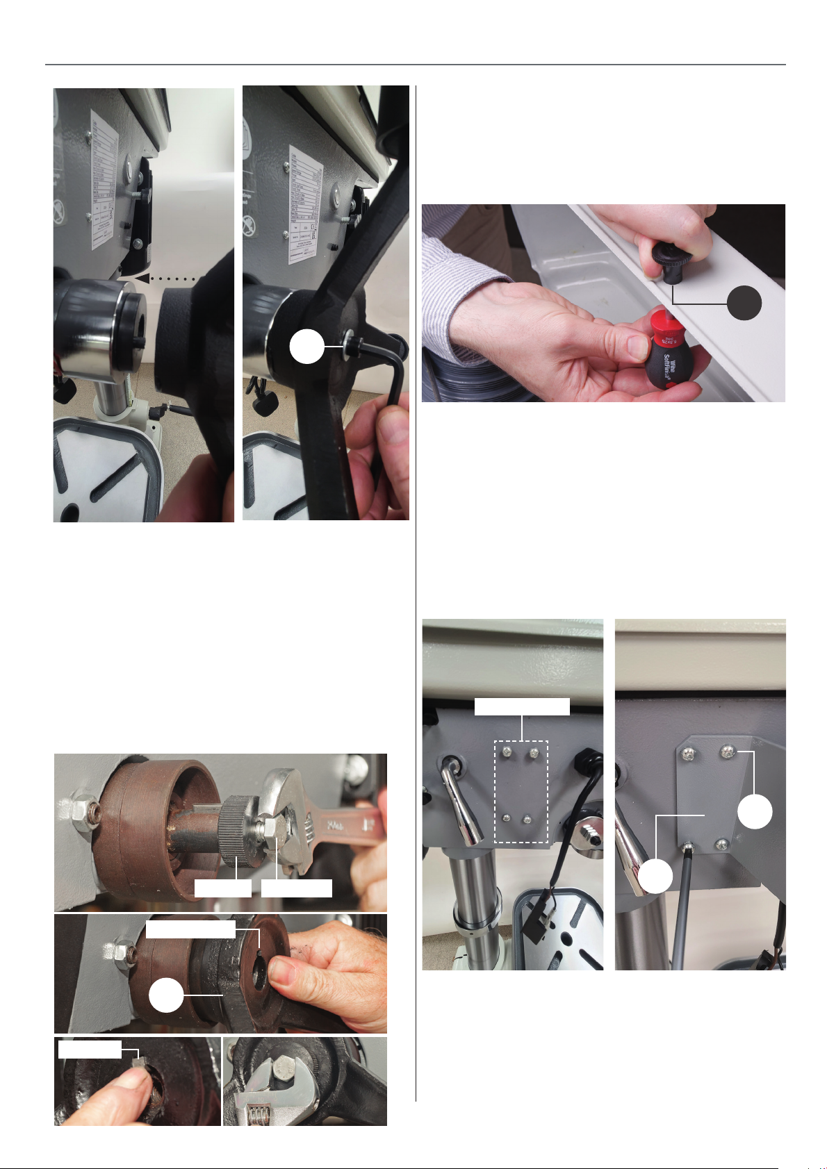
9
ASSEMBLY
Pulley Cover Knob
3. Locate the pulley cover knob (13), remove the Phillips screw,
insert the screw through the pre-drilled hole in the pulley cover
and secure the knob in place, see g 27.
Fig 27
13
Chuck guard
4. Locate the chuck guard assembly (7), chuck guard mounting
bracket (6) and the four M6 button head Phillips screws (17).
Oer up the four pre-drilled holes in the mounting bracket (6)
with threaded holes to the side of the drill head assembly (3).
Secure in position with the four M6 screws (17), see g 28-29
Lever Feed Handle (AP32FD ONLY)
Locate the lever feed handle (9), remove the centre bolt and
unscrew the centre cap from the raised boss drive shaft,
place safely aside, see g 24. Remove the square key from
the machined slot on the drive shaft. Mount the handle over
the drive shaft so the square cut out on the handle lines up
with machined slot in the shaft. Replace the square key,
screw on the centre cap and secure the handle in place with
the centre bolt, see g 25-26.
Fig 24-25-26
Centre cap Centre bolt
Key slot cut out
NOTE: Make sure the cutout slot in the mounting bracket (6)
is to the top.
Fig 28-29
Threaded holes
17
6
Square key
9
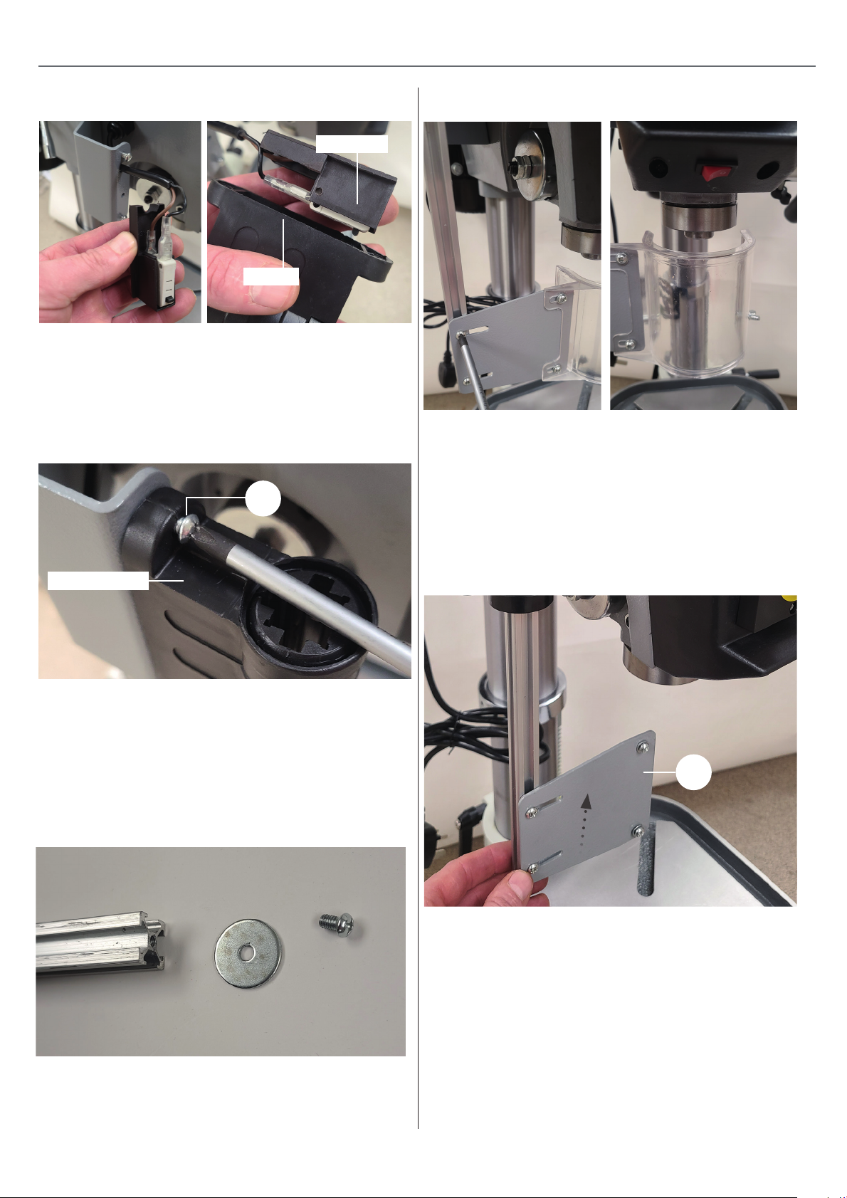
5. Insert the micro switch cable into the machined cutout slot
in the mounting bracket (6). Press the switch assembly into the
rear of the micro switch housing as shown, see g 30.
11
Continues Over....
Page 12
ASSEMBLY
Fig30
Micro switch
Housing
6. Line up the two holes in the micro switch unit with the
threaded holes to the end of the angled bracket (6). Make
sure to introduce the micro switch cable into the cutout slot
in the mounting bracket (6). Secure the micro switch with two
M5 Phillips screws (18), see g 31.
Fig 31
18
Fig 33-34
8a. The guard can be centralized via the 2 screws & plate slots.
9. Introduce the chuck guard rail (7) up through the centre of
the micro switch and nip up the clamping knob to lock the
chuck guard in place, see g 35.
Micro switch unit
7. Undo the clamping knob to the side of the micro switch
suciently to allow the guard rail to slide up through the
centre of switch.
8. Remove stop cap, remember to replace once tted.
Fig 32
NOTE: You can re-adjust the guard’s height for dierent
drilling operations.
Fig 35
7
Morse taper arbor and chuck
10. Locate the keyless chuck (11) and Morse taper arbor (12).
Insert the Morse taper arbor into the keyless chuck then slot
the assembly up into the quill. NOTE: DO NOT FORCE THE
MORSE TAPER IN, OTHERWISE THE QUILLS SPLINE SHAFT
WILL BE DAMAGED! Place a piece of timber on the table, turn
the lever feed handle (9) down until the chuck is up against the
timber and press lightly down. The Morse taper (12) should
now be locked inside the quill, see g 36-37-38.
12
Page 13

ASSEMBLY
Fig 36
Fig 37
12
11
NOTE: MAKE SURE ALL MATING SURFACES
ARE GREASE FREE BEFORE ASSEMBLY!
11. Open the pulley cover and check to see if the belt has been
tensioned. If not, loosen the two motor yoke locks on either
side of the drill head and move the tensioning lever back then
re-tighten the motor yoke locks to lock the motor in place, see
g 39-40-41-42.
Fig 39-40-41-42
Motor yoke clamp
Fig 38
Tension the belt
13
Page 14
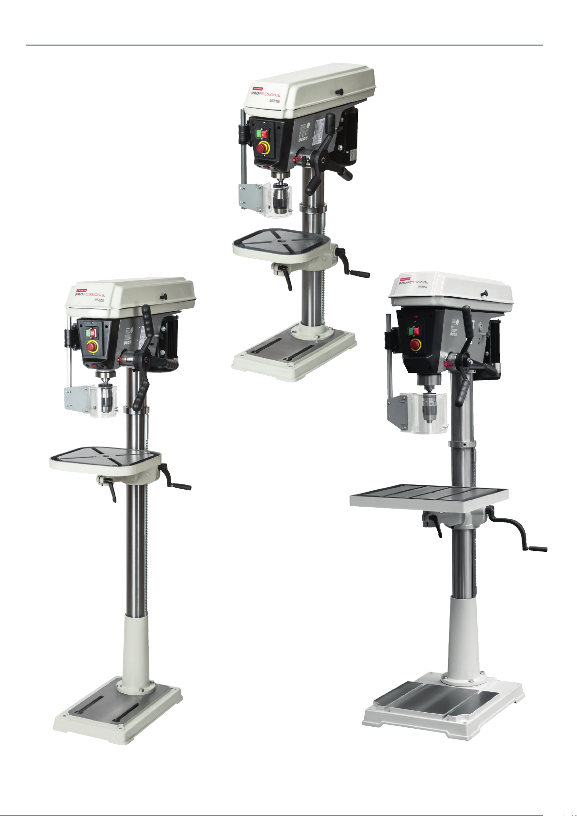
ILLUSTRATION AND PARTS DESCRIPTION
111891 AP20BD
111892 AP25FD
111893 AP32FD
14
Page 15
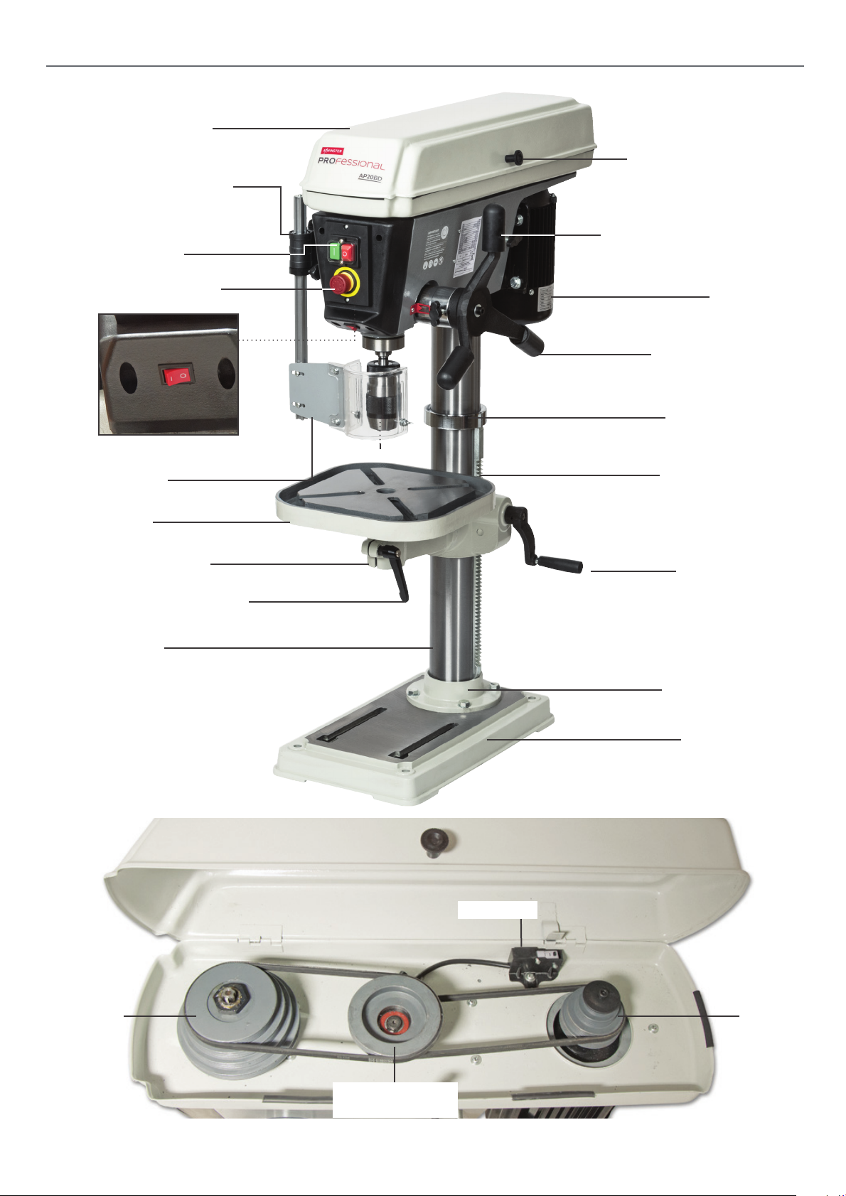
Pulley drive belt cover
Chuck guard micro switch
On/O switch
ILLUSTRATION AND PARTS DESCRIPTION
Pulley cover hand knob
Motor yoke buttery locking
Emergency stop Button
LED Light switch
Chuck guard
Drill table
Extension bracket arm
Lift and shift clamping handle
Drill column
Motor
Lever feed handle
Retaining collar
Keyless chuck
Rise and fall rack
Crank handle
Mounting ange
Base casting
Micro switch
Quill pulley Motor pulley
Jockey Pulley
(Drive belt tensioning)
15
Page 16
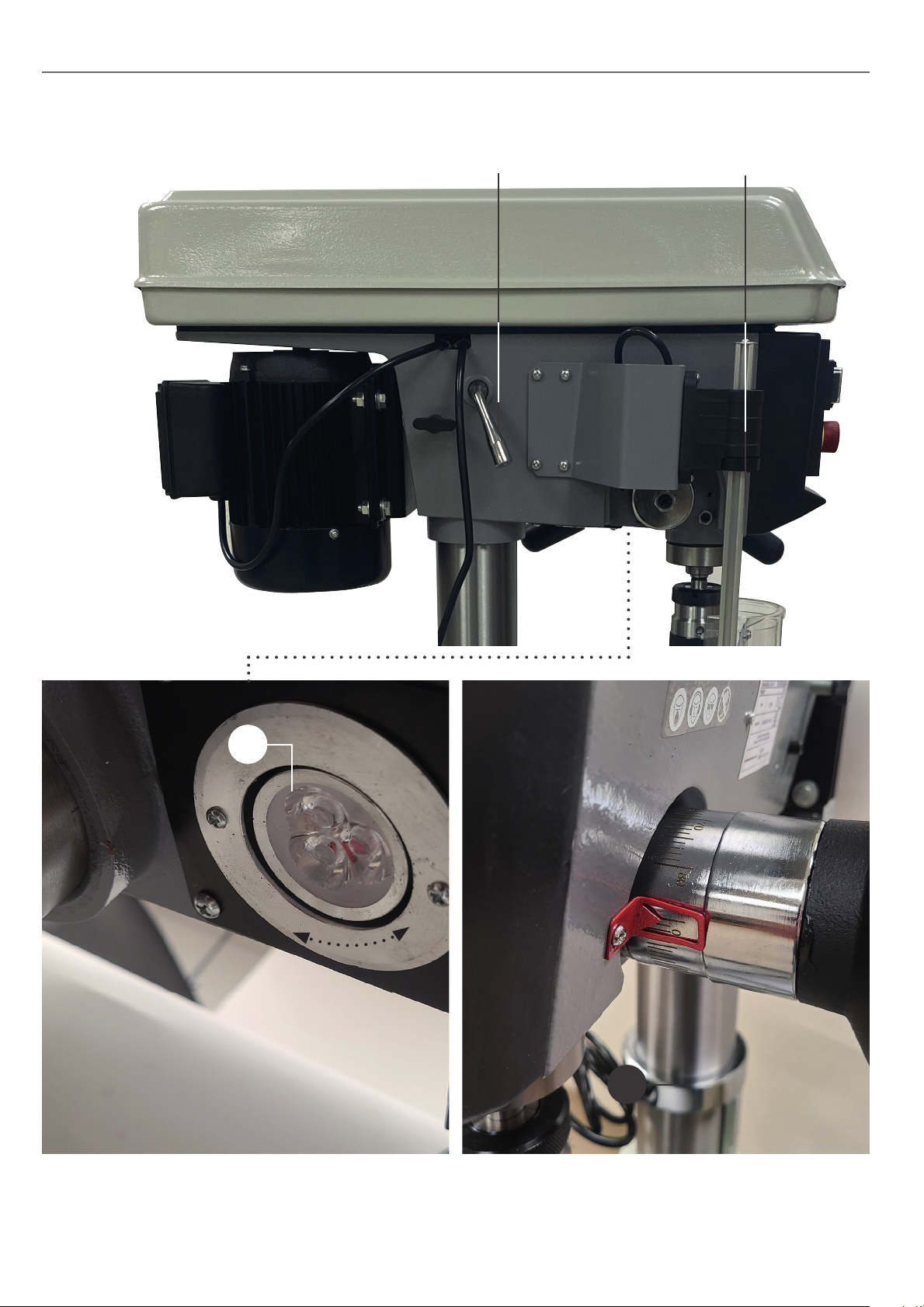
ILLUSTRATION AND PARTS DESCRIPTION
Drive belt tensioning lever lock
Move the tensioning lever to release
or tension the drive belts
Chuck guard micro switch
Opening the chuck guard
whilst in operation will stop
the drill instantly.
A
LED light (A) below the drill head pivots to
direct light down onto the work table
A
Depth stop assembly
16
Page 17
A
ILLUSTRATION AND PARTS DESCRIPTION
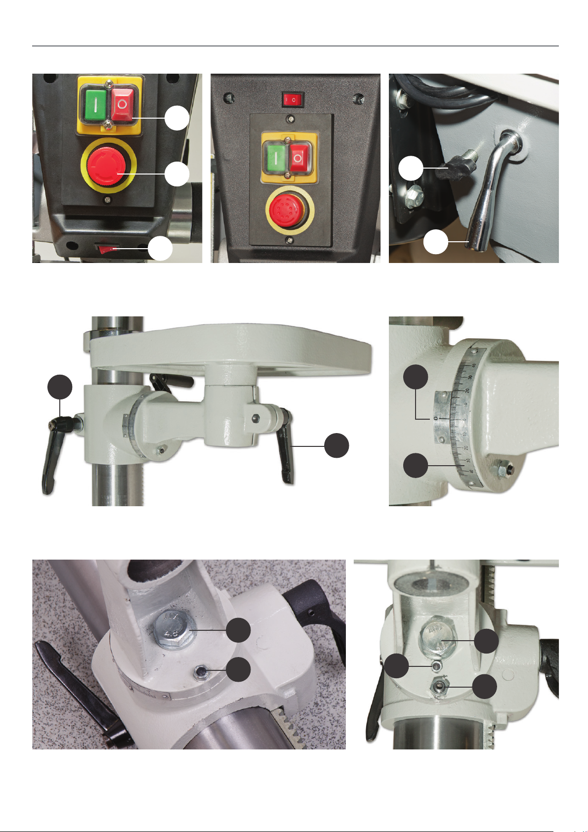
On/O switch (A)
Emergency stop button (B)
LED light switch (C)
A
C
B
AP32FD pillar drill control panel
NOTE: The LED light switch is above
the On/O switch assembly
B
A
B
Motor yoke buttery lock (A)
Drive belt tensioning lever lock (B)
A
Lift and shift handle (A) for securing the table mounting arm
Clamping handle (B) for securing the table
A
B
B
Table tilt pointer (A)
Table tilt scale (B)
A
B
C
Table tilt clamping bolt (A), 90˚ degrees locking pin (B) AP32FD Pillar drill table tilt assembly
Table tilt clamping bolt (A)
90˚ degree locking pin (B)
17
Table levelling adjusting nut (C)
Page 18
CHANGING THE SPEED
WARNING! DISCONNECT THE PILLAR
DRILL FROM THE MAINS SUPPLY BEFORE
CONTINUING!
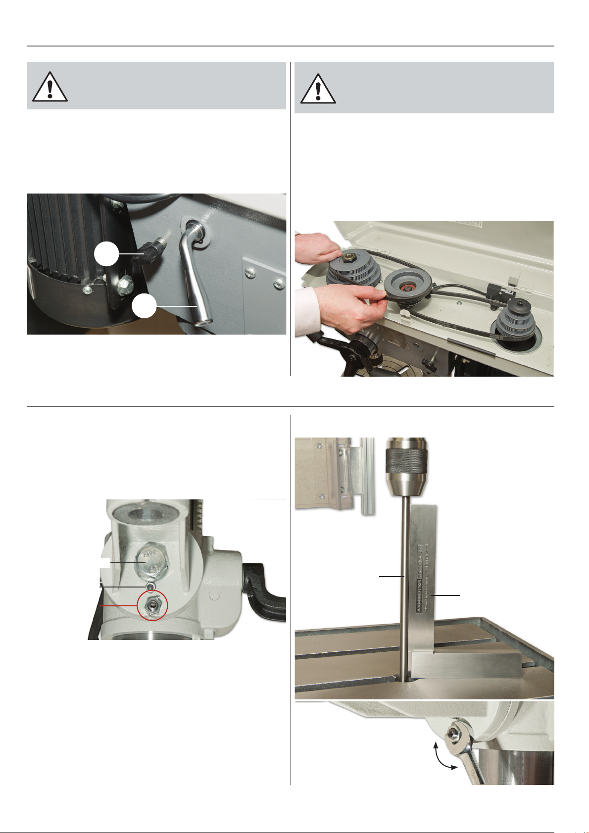
1. Open the pulley cover and loosen the motor yoke locks (A).
Turn the drive belt tensioning lever (B) anti-clockwise, to move
the motor assembly “in”. This will release the tension from the
drive belts, see g 43.
Fig 43
A
B
2. Refer to the speed select table and ascertain the belt
positions for the speed you require. Move the belts to these
positions.
WARNING! TAKE CARE NOT TO TRAP YOUR
FINGERS WHEN REPOSITIONING THE BELT
ON THE PULLEYS!
3. Turn the pulley train,see g 44, to check the belts move
freely. Tension the whole belt train by turning the drive belt
tensioning lever (B) anti-clockwise, to move the motor
assembly “out”. Tighten the motor yoke buttery knobs (A)
to lock the motor assembly in position.
Fig 44
LEVELLING THE TABLE (AP32FD ONLY)
The ‘AP32FD pillar drill’ come with a large heavy cast iron
table and there is more chance that the table will need to
be adjusted so it’s perpendicular with the motion of the quill.
To do this there is an adjusting nut on the supporting arm
below the 90˚ locking pin, see g 45.
Fig 45
Tilt clamping bolt
90˚ locking pin
Adjusting nut
1. Position the centre of the table directly beneath the pillar
drill’s chuck and lock the table in place. The table should be
about 200mm beneath the bottom of the chuck, nd a
perfectly cylindrical steel rod about 12.5mm in diameter
and insert it into the chucks jaws and tighten.
Fig 46-47
Cylindrical steel rod
Square
2. Position a 90˚ square on the table and line it against the
steel rod. If you notice any unevenness between the table
and the rod, loosen the tilt clamping bolt and turn the
adjusting nut until the table is square with the drill chuck. Tighten the clamping bolt to lock the table in place, see 46-47.
18
Page 19
TILTING THE TABLE
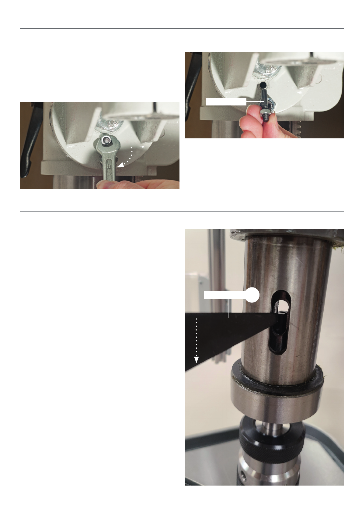
1. The cust iron table can be tilted 45˚ degrees in both plains,
to tilt the table you will need to rst remove the tables 90˚
locking pin. To remove the locking pin use a 10mm spanner,
turn the nut clockwise to draw the pin out. Remove the pin and
place safely aside, see g 48-49. Loosen the tilt clamping bolt
and tilt the table to the desired angle then retighten the bolt.
Fig 48
Fig 49
90˚ Locking pin
2. To set the table back to 90˚ degrees, loosen the clamping
bolt, position the table back in the horizontal plain and insert
the locking pin into the machined hole in the support arm.
Adjust the nut so it protects the end of the threaded pin and
using a high faced mallet tap the locking pin into place.
REMOVING THE KEYLESS CHUCK
1. Lower the quill to its maximum depth by turning the
feed lever handle. Whilst holding the quill handle down rotate
the depth stop collar to keep the quill locked down.
2. Place a piece of timber on the drill table to prevent the
chuck from being damaged, turn the chuck to line up the
Morse taper arbor in the quill’s machined slot. Insert the Morse
taper drift (14) in the quill’s slot, thus pushing the Morse taper
down and releasing the chuck assembly, see g 51.
Morse taper drift
Fig 51
14
19
Page 20

MAINTENANCE
WARNING! DISCONNECT THE MACHINE
FROM THE MAINS SUPPLY BEFORE
CONTINUING!
Cleaning
Excessive dust in the motor can cause excessive heat to
develop. Every eort should be made to prevent foreign
material from entering the motor.
When operated under conditions likely to permit
accumulations of dust, dirt or waste, a visual inspection
should be made at frequent intervals. Accumulations of dry
dust can usually be blown out successfully.
Caution: To avoid eye injury or adverse reaction to dust,
high pressure hoses should not be used especially in poorly
ventilated areas. The operator performing this cleaning
function should wear safety goggles and dust lter mask.
After cleaning, apply a light coat of machine oil on the quill
and chuck.
If the machine is going to stand idle for any length of time, a
light coat of spray or machine oil over the column and table
will prevent rusting. Then place a dust sheet over the pillar drill.
Electric
WARNING! DO NOT USE THE MACHINE
IF THE POWER CABLE HAS BECOME
DAMAGED.
If any servicing (other than the above cleaning) becomes
necessary, the unit should be returned to Axminster Tools to be
repaired by one of our qualied electricians. Contact our
customer sales department for further assisance on 03332
406406 or email as @ csaxminstertools.com
Call: 03332 406406
Email: [email protected]
WARNING! DO NOT ATTEMPT TO REPAIR
IT YOURSELF CONTACT OUR TECHNICAL
SALES TEAM FOR ASSISTANCE.
Motor speed
The speed of the motor cannot be regulated or changed - no
adjustment is necessary.
20
Page 21
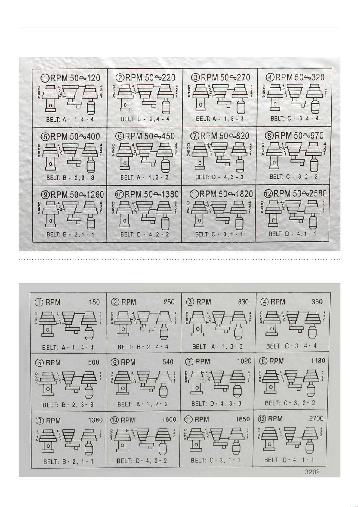
SPEED SELECT TABLES
(12 Speed) 111891 AP20BD Bench Pillar Drill 111892 AP25FD Floor Pillar Drill
(12 Speed) 111893 AP32FD Floor Pillar Drill
21
Page 22
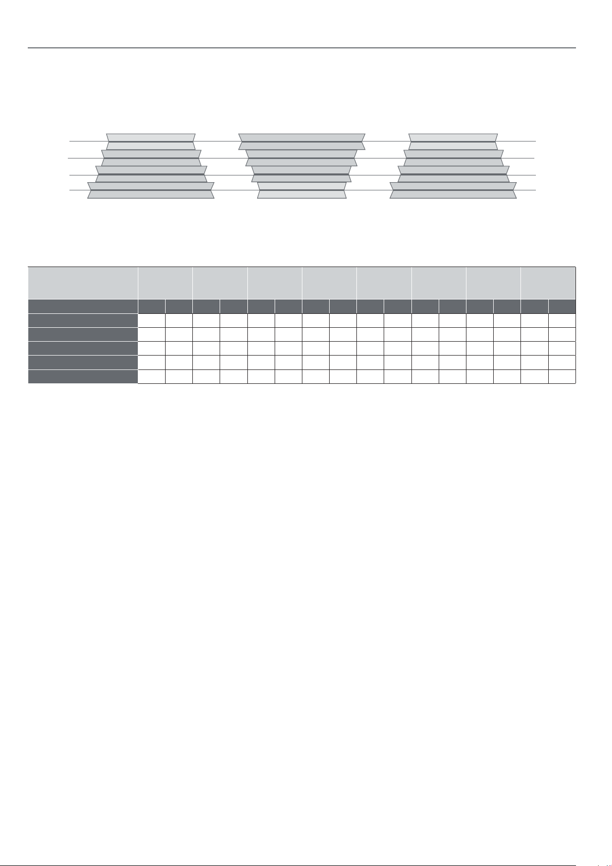
DRILL SPEED MATERIAL TABLE
12 Speed
Spindle MotorJockey Pulley
D
C
B
A
Recommended Drill Size per Material
Average Guide
Speed
50Hz inches mm inches mm inches mm inches mm inches mm inches mm inches mm inches mm
2450-2500-2580 rpm 5/16” 7.9 3/16 4.8 11/64 4.4 5/32 4.0 7/16 2.8 3/32 2.4 1/16 1.6 1/32 0.8
1580-1750-1870 rpm 3/8 9.5 1/4 6.4 7/32 5.6 3/16 4.8 1/8 3.2 3/32 2.4 1/16 1.6 3/64 1.2
1250-1290-1330 rpm 5/8 15.9 3/8 9.5 11/32 8.7 5/16 7.9 1/4 6.4 5/32 4.0 1/8 3.2 1/16 1.6
790-830-900 rpm 7/8 22.2 1/2 12.7 15/32 11.9 7/16 11.1 11/32 8.7 1/4 6.4 3/16 4.8 1/8 3.2
500-540-600 rpm 1
Wood
1
/4 31.8 3/4 19 11/16 17.5 5/8 15.9 1/2 12.7 3/8 9.5 5/16 7.9 1/4 6.4
Zinc
Diecast
Aluminium
or Brass
Plastic
Cast Iron
and Bronze
Steel
Mild and
Malleable
Steel Cast
and
Carbon
Stanless and
4
3
2
1
Steel
Too l
22
Page 23

TROUBLE PROBABLE CAUSE REMEDY
TROUBLESHOOTING
Noisy Operation
Drill bit burns
Drill bit leads o hole not round
Wood splinters on underside
1. Incorrect belt tension
2. Dry spindle
3. Loose spindle pulley
4. Loose motor pulley
1. Incorrect speed
2. Chips not coming out of hole
3. Dull drill bit
4. Feeding too slow
5. Not lubricated
1. Hard grain in wood or lengths of
cutting lips and/or angles not equal
2. Bent drill bit
1. No “back-up material” under
workpiece
1. Adjust the tension
2. Lubricate spindle
3. Checking tightness of
retaining nut on pulley,
and tighten if necessary
4. Tighten set screws in pulleys
1. Change speed
2. Retract drill bit frequently
to clear chips
3. Resharpen drill bit
4. Feed fast enough-allow drill
bit to cut.
5. Lubricate drill bit
1. Resharpen drill bit correctly
2. Replace drill bit
1. Use “back-up material”
Work piece torn loose from hand
Drill bit binds in work piece
Excessive drill bit run out or wobble
Quill returns too slow or too fast
Chuck will not stay attached to
spindle it falls o when trying to
install it
1. Not supported or clamped
properly
1. Work piece pinching drill bit
or excessive feed pressure
2. Improper belt tension
1. Bent drill bit
2. Worn spindle bearings
3. Drill bit not properly
installed in chuck
4. Chuck not properly installed
1. Spring has improper tension 1. Adjust spring tension
1. Dirty, grease or oil on the tapered
inside surface of chuck or on the
spindle’s tapered surface
1. Support work piece or clamp it
1. Support work piece or clamp it
2. Adjust tension
1. Use a straight drill bit
2. Replace bearings
3. Install drill bit properly
4. Install chuck properly
1. Make sure all surfaces are free of dust
and grease
23
Page 24
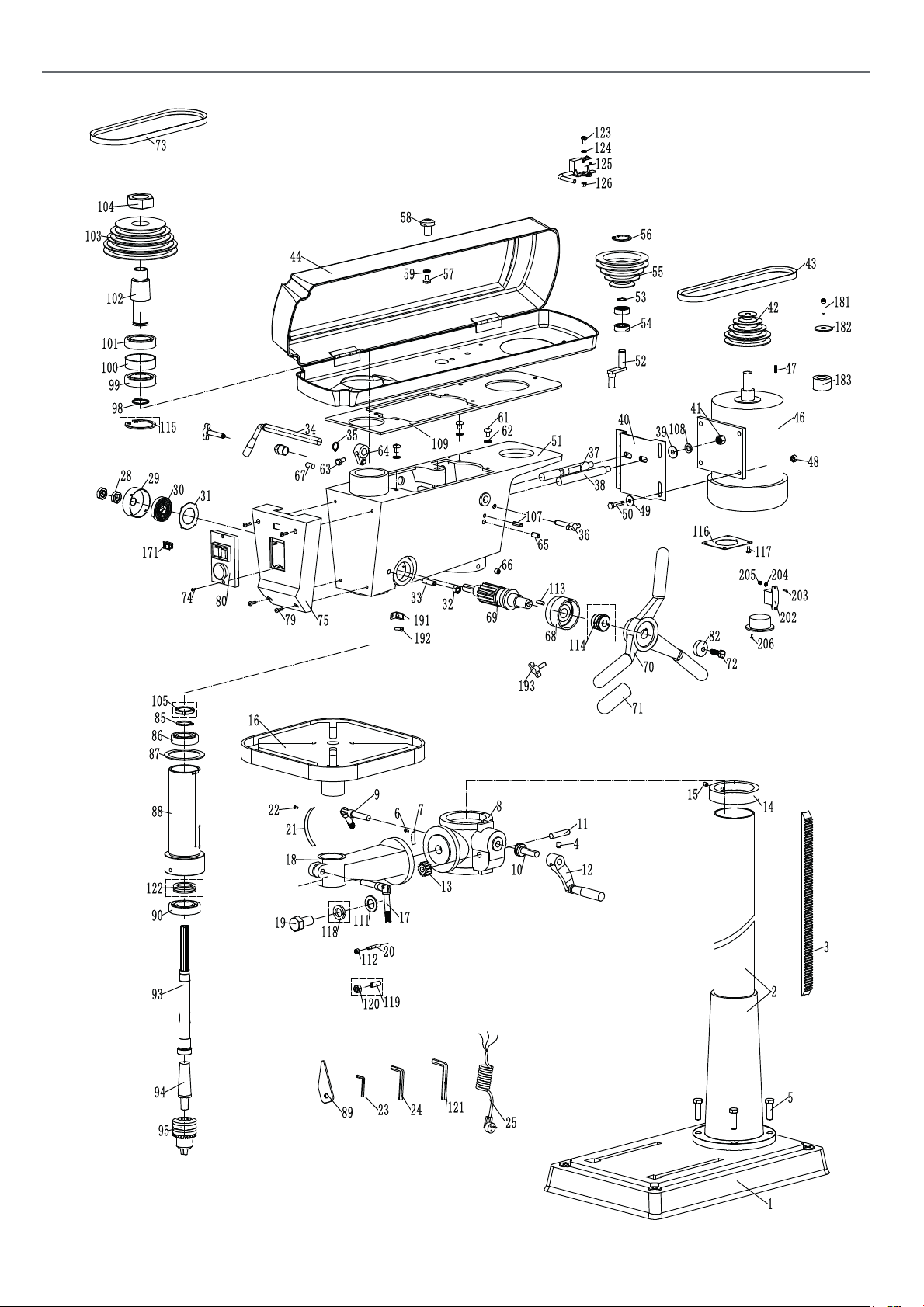
EXPLODED DIAGRAM/PARTS LIST
EXPLODED DIAGRAM/PARTS LIST
24
Page 25

EXPLODED DIAGRAM/PARTS LIST
PART
DESCRIPTION QTY
NO
1 BASE 1
2 COLUMN 1
3 RACK 1
4 HEX SCREW 1
5 BOLT 4
6 RIVET 2
7 SCALE 1
8 GRIPPING SLEEVE 1
9 LOCKING HANDLE 1
10 WORM 1
11 SMALL SHAFT 1
12 ROCKER 1
13 BEVEL WHEEL 1
14 COLLAR 1
15 SCREW 1
16 TABLE 1
17 LOCKING HANDLE 1
18 ARM 1
19 BOLT 1
20 PIN 1
21 ANGLE SCALE 1
22 RIVET 2
23 WRENCH 1
24 WRENCH 1
25 POWER CORD 1
28 NUT 2
29 SPRING SEAT 1
30 SPRING 1
31 WASHER 1
32 NUT 1
33 HEX HEAD SCREW 1
34 HANDLE FOR TENSION 1
35 CHECK RING 1
36 HANDLE 2
37 INITIATIVE GUIDE ROD 1
38 DRIVEN GUIDE ROD 1
39 WASHER 12 2
40 MOTOR BASE 1
41 NUT M12 2
42 DRIVER PULLEY 1
43 BELT 1
44 BELT COVER 1
46 MOTOR 1
47 FLAT KEY 1
48 NUT M8 4
49 WASHER 8 4
50 BOLT 4
51 CAST BODY 1
52 IDLE PULLEY SHAFT 1
53 CHECK RING 1
54 BEARING 1
55 IDLE PULLEY 1
56 CHECK RING 1
57 BOLT 1
58 HANDLE 1
59 WASHER 1
61 BOLT 4
62 WASHER 4
63 BOLT M8X16 1
64 SHIFTING FORK 1
65 HEX SOCKET TACKING 1
66 HEX SOCKET TACKING 1
67 HEX SOCKET TACKING 1
68 COVER 1
69 GEAR SHAFT 1
70 HANDLE ASSEMBLY 1
71 HANDLE COVER 3
72 BOLT 1
73 BELT 1
74 SCREW 3
75 SWITCH BOX 1
79 BOLT 4
80 SWITCH 1
85 WASHER 1
86 BEARING 1
87 RUBBER PAD 1
88 SLEEVE 1
89 DRIFT 1
90 BEARING 1
93 MAIN SHAFT 1
94 LIVE AXLE 1
95 CHUCK 1
25
Page 26
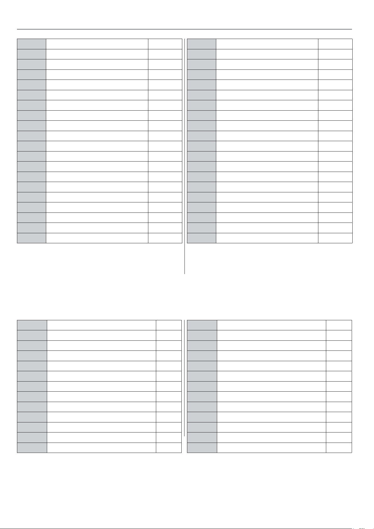
EXPLODED DIAGRAM/PARTS LIST
98 CIRCLIP 1
99 BEARING 1
100 SPACER SLEEVE 1
101 BEARING 1
102 SPINDLE HOUSING 1
103 DRIVEN PULLEY 1
104 NUT 1
105 NUT 1
107 PIN 1
108 WASHER 2
109 ANTI-VIBRATION PAD 1
111 WASHER 1
112 NUT M6 1
113 KEY 1
114 CONNECTING SHAFT 1
115 CHECK RING 2
116 COVER 1
117 BOLT 4
118 WASHER 1
119 SCREW 1
120 NUT 1
121 WRENCH 1
122 THRUST BEARING 1
123 BOLT M6X12 1
124 WASHER 1
125 MICRO SWITCH 1
126 NUT M6 1
171 SWITCH 1
181 BOLT 1
182 WASHER 1
183 SHAFT SLEEVE 1
191 POINTER 1
192 SCREW 1
193 HANDLE 1
202 LED LIGHT 1
203 BOLT 2
204 WASHER 2
205 NUT 2
206 BOLT 2
NO DESCRIPTION QTY
2-1 BOLT M5X16 2
2-2 BASE 1
2-3 STEEL BALL 1
2-4 SHRAPNEL 1
2-5 BOLT M4X6 2
2-6 MICRO SWITCH 1
2-7 COVER PLATE 1
2-8 GUIDE SLEEVE 1
2-9 LOCKING HANDLE 1
2-10 GUIDE PILLAR 1
2-11 SLIDING BLOCK 2
2-12 BOLT 2
2-13 GUARD 1
2-14 DEAD PLATE 1
2-15 BOLT 4
2-16 CABLE GLAND 1
2-17 MOUNTING PLATE 1
2-18 BOLT 2
2-19 NUT M5 2
2-20 WASHER 5 2
2-21 SCREW 1
2-22 WASHER 1
2-23 BOLT M6X16 2
2-24 WASHERS 2
2-25 BENCH AND FLOOR DRILL 2
26
Page 27
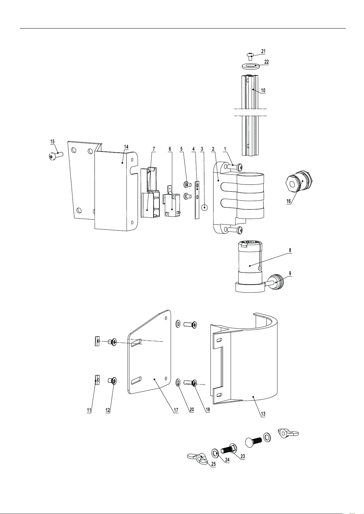
EXPLODED DIAGRAM/PARTS LIST
EXPLODED DIAGRAM/PARTS LIST
27
Page 28
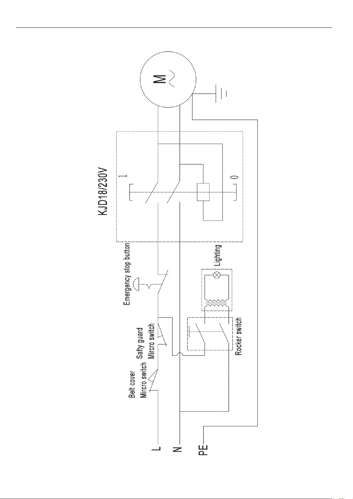
WIRING DIAGRAM
28
Page 29
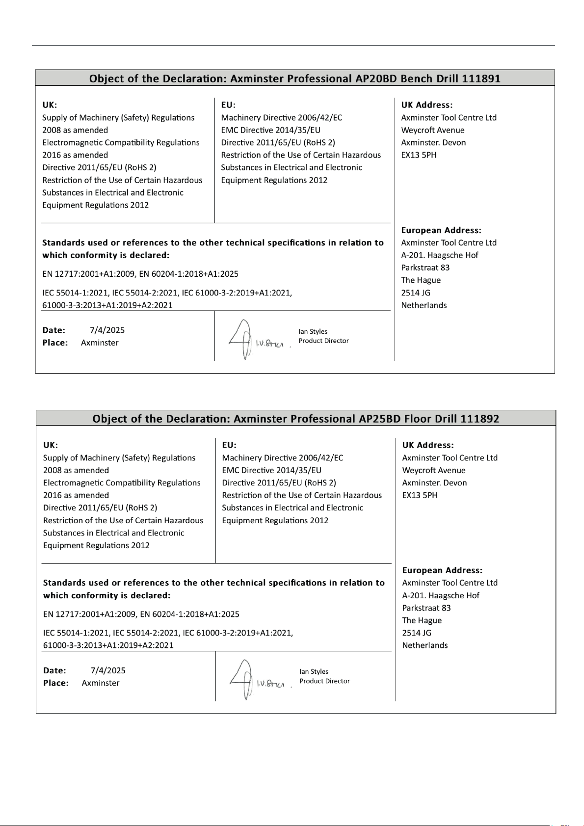
DECLARATION OF CONFORMITY
29
Page 30
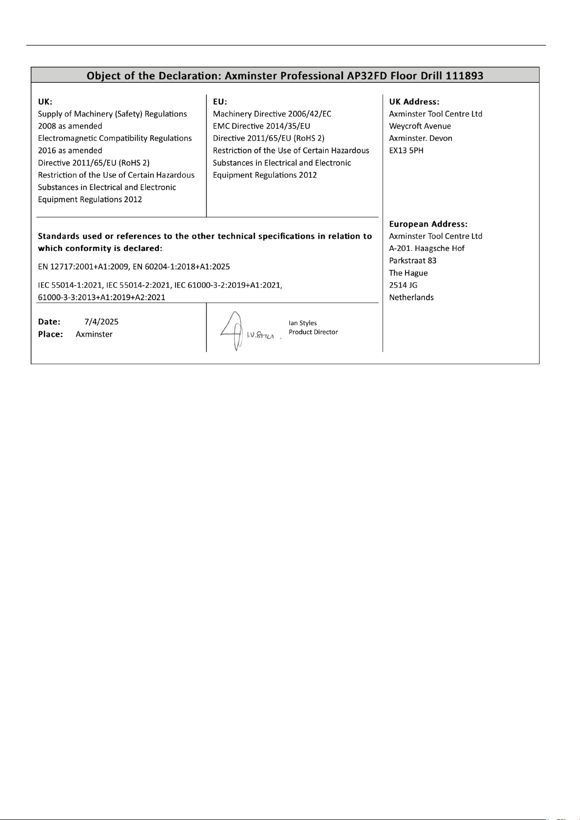
DECLARATION OF CONFORMITY
30
Page 31

31
Page 32

The packaging is suitable for recycling.
Please dispose of it in a responsible manner.
EU Countries Only
Do not dispose of electric tools together with household waste material.
By law they must be collected and recycled separately.
Axminster Tools, Axminster Devon EX13 5PH
axminstertools.com
 Loading...