

Page 1
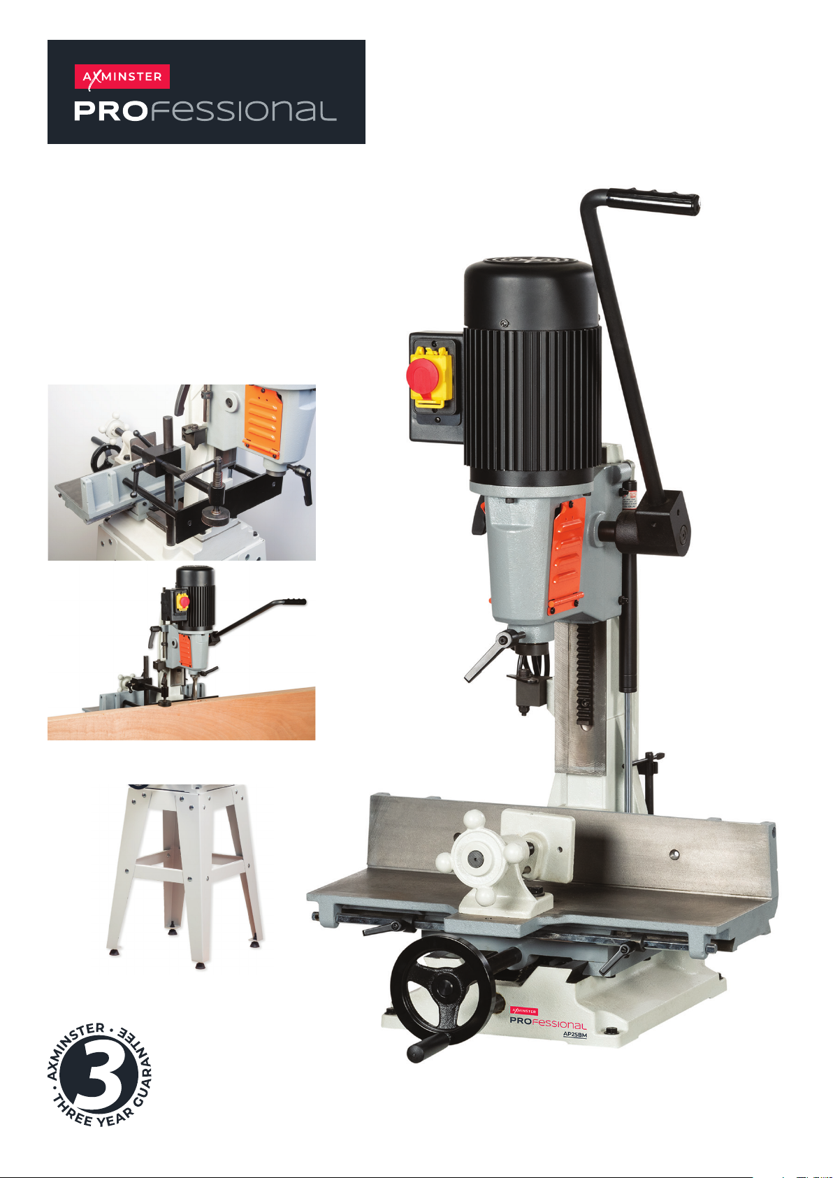
AP25BM
Bench Morticer
Code 105646 Door Mortice Kit
Code 107638
Original Instructions
Code 105645 AP25BM Morticer Stand
AT: 06/10/2023
BOOK REF : 106517
Page 2
INDEX OF CONTENTS
EU Declaration of Conformity 02
What’s Included 03
Optional Accessories 04
General Safety Instructions for 230V Machines 05
Specic Safety Instruction for Morticers 05
Specication 05
Assembly 06-07-08
Illustration and Parts Description 09-10-11
Setting Up the Morticer 12-13-14-15-16
Accessories 17-18-19
Maintenance 19-20-21
Troubleshooting 22
Exploded Diagrams/Lists 23-24-25-26
Wiring Diagram 27
EU DECLARATION OF CONFORMITY
Cert No: 2310
Axminster Tool Centre Ltd
Axminster Devon
EX13 5PH UK
axminstertools.com
declares that the machinery described:-
Type Morticer
Model AP25BM
Signed
Andrew Parkhouse
Operations Director
Date: 18/10/2017
EU Declaration of Conformity
This machine complies with the following directives:
2006/42/EC
EN ISO 12100
EN 60204-1:2006/AC:2010
and conforms to the machinery example for which the
EC Type-Examination Certicate No RA/2017/A0001C
has been issued by Yeon Chuan Machinery Co., Ltd
at: 50-2, Lane 108, Yongfeng RD., Taiping Dist., Taichung City, Taiwan 411.
and complies with the relevant essential health and safety requirements.
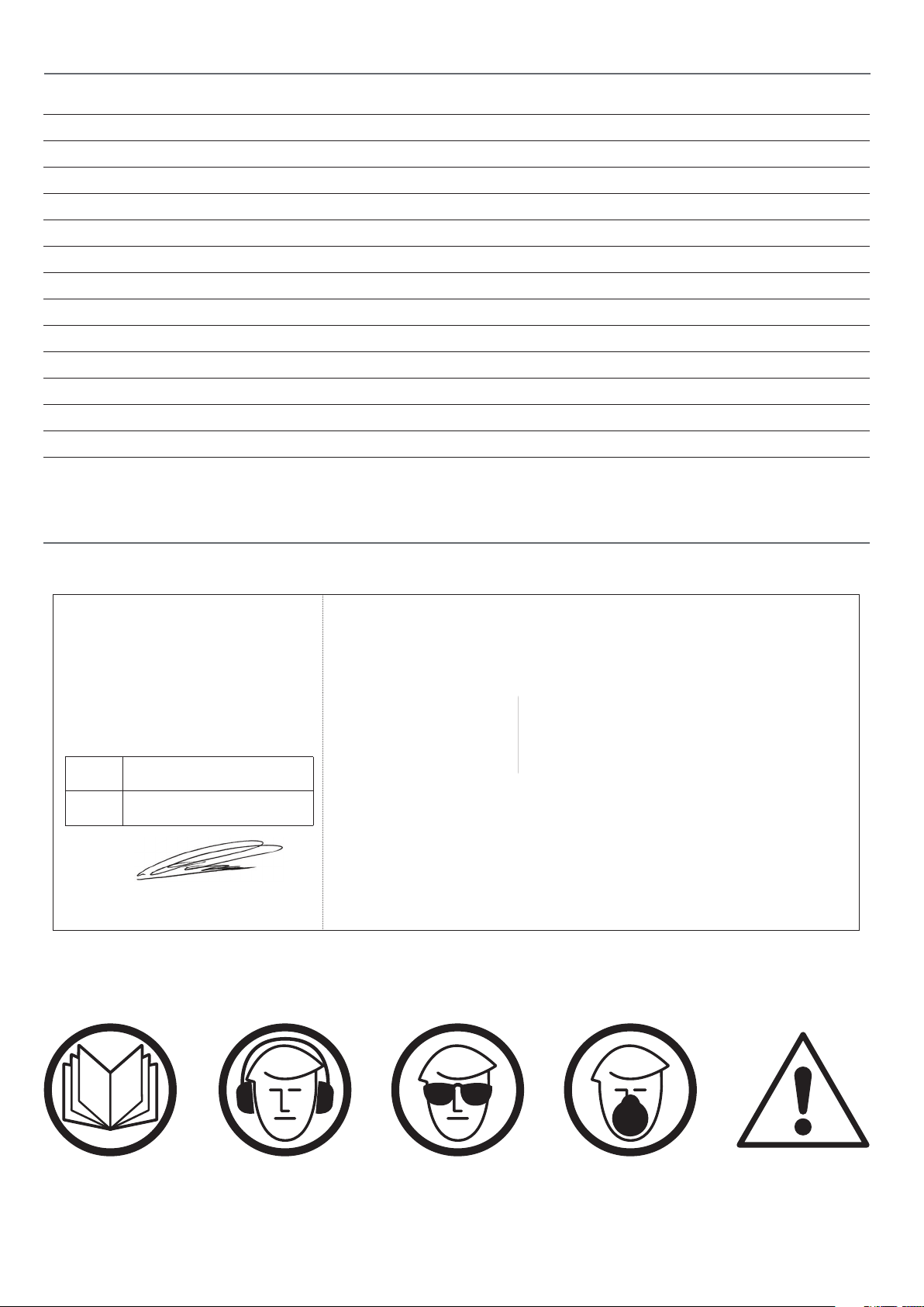
The symbols below advise the correct safety procedures when using this machine.
Fully read manual
and safety instructions
before use
Ear protection
should be worn
Eye protection
should be worn
2
Dust mask
should be worn
HAZARD
Page 3
WHAT’S INCLUDED
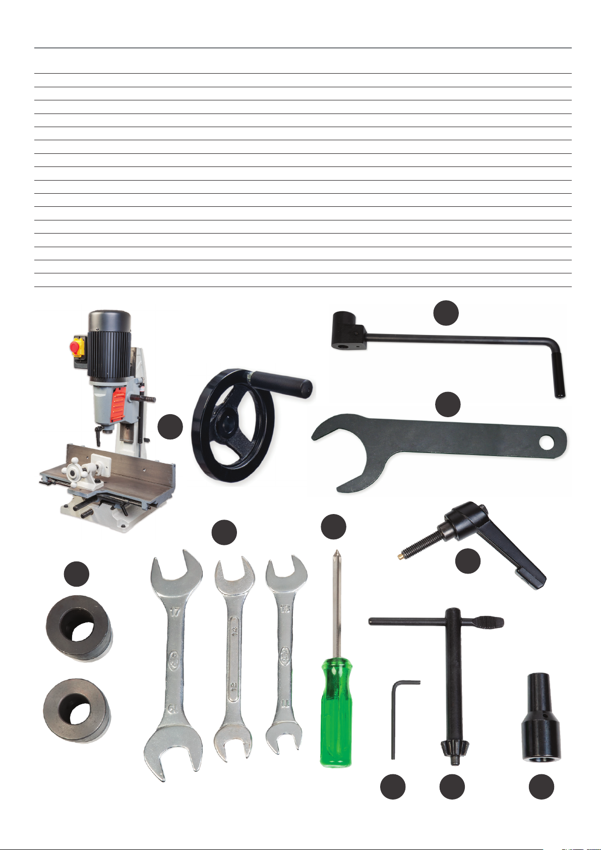
Quantity Item Part Model Number
AP25BM
1 Bench Morticer A
1 Operating Wheel
1 Operating Lever B
Accessories
2 Bush Adaptors 13/16" and 3/4" C
1 17-19, 12-14 and 11-13mm Spanners D
1 Spindle Nut Spanner
1 Screwdriver E
1 Hex Key F
1 Chuck Key G
1 Lift & Shift Clamping Handle H
1 Chuck Extension I
1 Instruction Manual
B
C
A
D
D
E
H
F G I
3
Page 4
OPTIONAL ACCESSORIES
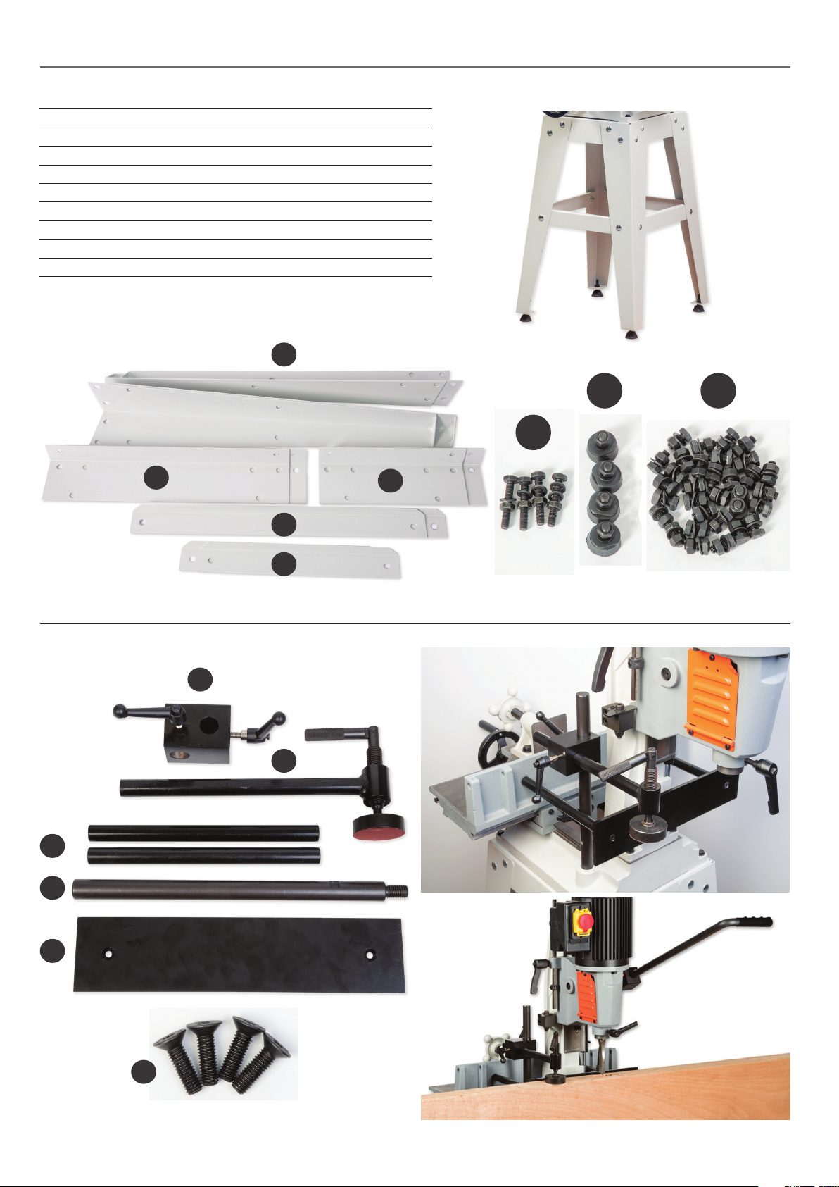
Code: 105645 Stand Assembly
4 Leg Brackets J
2 Long Upper Support Struts K
2 Short Upper Support Struts L
2 Long Lower Support Struts M
2 Short Lower Support Struts N
4 M8 Hex Bolts Washers & Nuts O
4 Threaded Rubber Feet P
1 Bag of Fixings Q
J
P Q
O
K
Code: 105646 Door Mortice Kit
R
T
L
M
N
S
U
V
X
4
Page 5

GENERAL SAFETY INSTRUCTIONS FOR 230V MACHINES
The following will enable you to observe good working
practices, keep yourself and fellow workers safe and maintain
your tools and equipment in good working order.
WARNING!! KEEP TOOLS AND EQUIPMENT
OUT OF REACH OF YOUNG CHILDREN
KEEP WORK AREA AS UNCLUTTERED AS IS
PRACTICAL. UNDER NO CIRCUMSTANCES SHOULD
CHILDREN BE ALLOWED IN WORK AREAS.
Mains Powered Tools
• Tools are supplied with an attached 13 Amp plug.
• Inspect the cable and plug to ensure that neither are
damaged. Repair if necessary by a suitably qualied person.
• Do not use when or where it is liable to get wet.
Workplace
• Do not use 230V a.c. powered tools anywhere
within a site area that is ooded.
• Keep machine clean.
• Leave machine unplugged until work is about to commence.
• Always disconnect by pulling on the plug body and not the
cable.
• Carry out a nal check e.g. check the cutting tool
is securely tightened in the machine and the correct
speed and function set.
• Ensure you are comfortable before you start work,
balanced, not reaching etc.
• Wear appropriate safety clothing, goggles, gloves,
masks etc. Wear ear defenders at all times.
• If you have long hair wear a hair net or helmet to prevent it
being caught up in the rotating parts of the machine.
• Consideration should be given to the removal of rings and
wristwatches.
• Consideration should also be given to non-slip footwear etc.
• If another person is to use the machine, ensure they are
suitably qualied to use it.
• Do not use the machine if you are tired or distracted
• Do not use this machine within the designated safety areas
of ammable liquid stores or in areas where there may be
volatile gases.
• Check cutters are correct type and size, are undamaged
and are kept clean and sharp, this will maintain their
operating performance and lessen the loading on the
machine.
• OBSERVE…. make sure you know what is happening
around you and USE YOUR COMMON SENSE.
SPECIFIC SAFETY INSTRUCTION FOR MORTICERS
• Ensure that the morticer is rmly xed to its base as the force
exerted through the operating handle could be enough to over
balance the machine.
• Ensure that the operating handle is returned to the
upright position after cutting a mortice.
• Mortice chisels have very sharp ends, handle them with
great care.
• Make sure that the timber is held rmly down against the
table, either with the vice or the hold down clamps. This
prevents the possibility of the timber being pulled upwards
as the mortice chisel is withdrawn from the hole.
SPECIFICATION
Code 107638
Model AP25BM
Rating Professional
Power 750W 230V 50Hz 1Phase
Chisel Stroke 125mm
Centre of Chisel to Back Fence 110mm
Max Height of Timber with 12.7mm Chisel and Bit 190mm
Max Chisel Size Softwood 25mm
Max Chisel Size Hardwood 19 mm
Overall L x W x H 460mm x 515mm x 1,000mm
Weight 85kg
5
Page 6
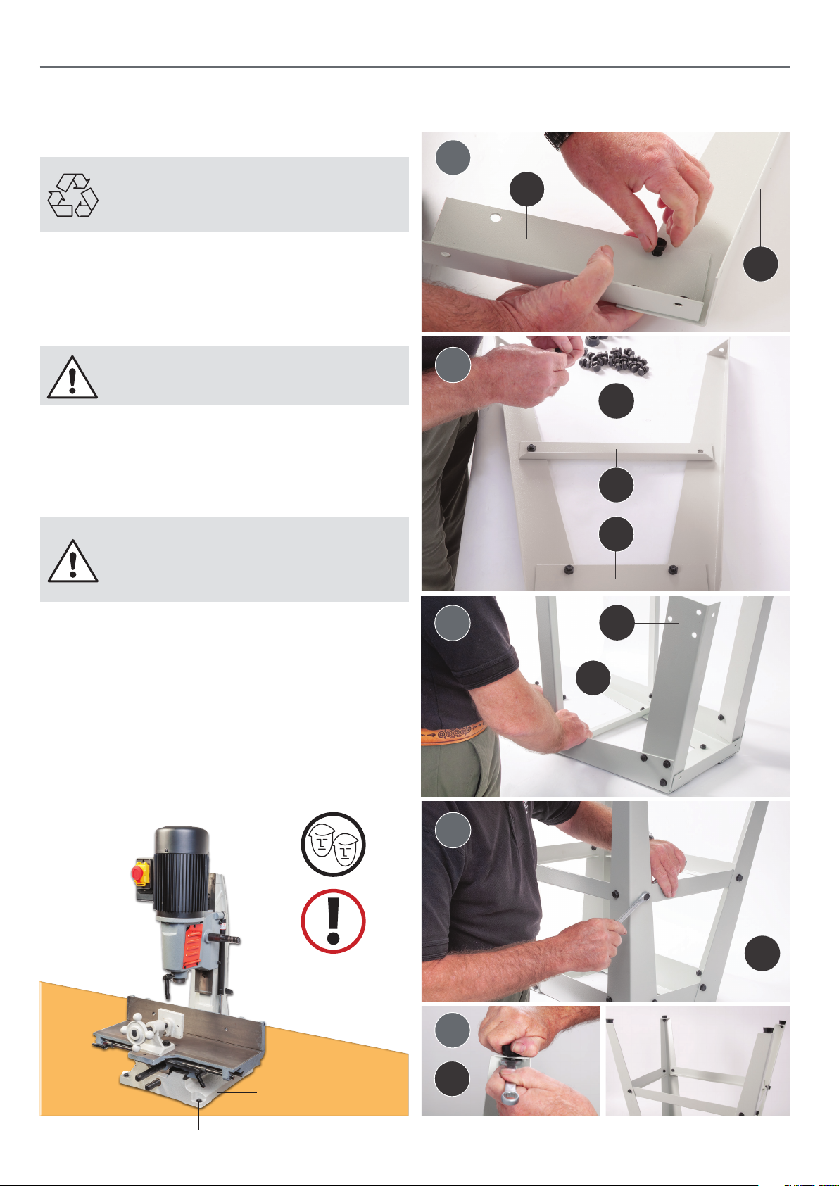
ASSEMBLY
Remove the morticer and parts from the shipping
cartons. Report any shortages or damage to Axminster Tool
Centre Customer Services Department. (03332 406406)
HAVING UNPACKED YOUR ACCESSORIES PLEASE
DISPOSE OF ANY UNWANTED PACKAGING
PROPERLY. THE POLYTHENE AND CARD IS
RECYCLABLE.
The machine and its accessories will arrive coated with heavy
corrosion preventative grease and greased wax paper. These
may need to be cleaned from the machine, its component
and accessories prior to it being set up. Use degreaser to
remove the barrier grease.
WEAR GLOVES AND EYE PROTECTION
WHILE CLEANING THE MACHINE!
Read the manual thoroughly, familiarising yourself with the
correct safety, operating and maintenance procedures before
proceeding further.
Mounting the Morticer to a Workbench
Optional Stand Assembly
Code 105645
1
L
J
2
Q
N
WARNING! YOU WILL REQUIRE
ASSISTANCE TO LIFT THE MORTICER OR
USE A HOIST OR ENGINE CRANE BEFORE
ATTEMPTING TO MOVE THIS MACHINE!
Lower the morticer assembly onto the workbench and
position the machine so there is sucient space all round.
Use a pencil and mark the position of the mounting holes to
the base casting. Drill the holes in the workbench and secure
the morticer using four M8 bolts/washers.
NOTE: Mount the morticer near the edge of the bench to
allow sucient clearence when using the optional ‘Door
Mortice Kit code 105645’. Consider purchasing the optional
stand, code 105645.
3
4
L
K
M
Base casting
Mounting hole
J
Workbench
5
P
6
Page 7
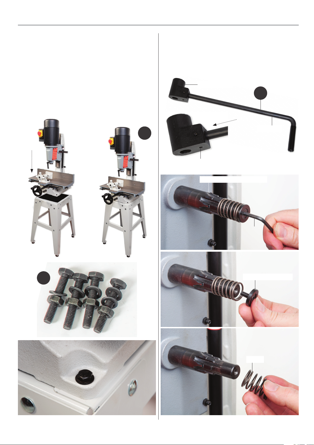
ASSEMBLY
Mounting the Morticer to the Stand
Locate the four M8 Hex bolts/washers (O). Lift the morticer (A)
onto the stand, line up the four pre-drilled holes to the base of
the morticer with the holes to the corners of the stand
assembly. Place a larger washer over the thread Hex bolts, insert
the bolts down through the holes in the morticer’s base. Place
the remaining washers over the threaded bolts and secure in
place with the four nuts, see g 01-02-03.
Fig 01-02-03
A
Operating Lever
1. Locate the operating lever (B). Loosen the grub scew on the
lever coupling, insert the bar into machined hole and re-tighten
the screw. Remove the Hex screw washer and spring from the
rack and pinion assembly, see gs 05-06-07.
Fig 04
Lever coupling
B
Lever bar
Grub screw
Fig 05-06-07
Rack and Pinion assembly
O
Hex key
Hex screw washer
Spring
7
Continues over...
Page 8
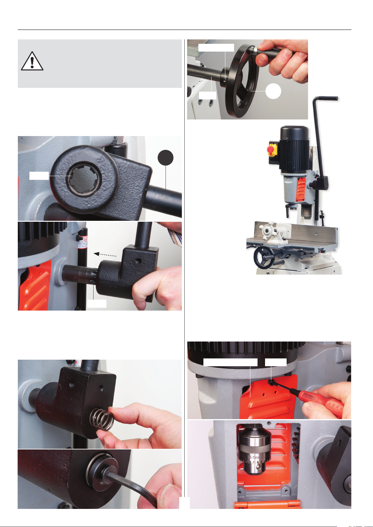
ASSEMBLY
IMPORTANT NOTE: THE HEAD STOCK ASSEMBLY
HAS BEEN LOWERED FOR SHIPPING AND NEEDS TO
BE RAISED TO ITS HIGHEST POSITION. TO DO THIS
INSERT THE LEVER COUPLING OVER THE PINION
ASSEMBLY UNTIL THE TEETH MESH THEN RAISE THE
HEAD STOCK.
2. Re-position the lever (B) coupling over the rack and pinion
assembly so that the lever is in the upright position and the
teeth are meshed together, see g 08-09.
Fig 08-09
B
Teeth
Grub screw
Shaft
4. Locate the operating wheel (A),
undo the grub screw and slide
the wheel onto the drive shaft
re-tighten the screw, see g 12.
Fig 12
A
Teeth
3. Push the lever coupling face up against the support column
and replace the spring and Hex screw washer. Re-tighten using
the Hex key, NOTE: DO NOT OVERTIGHTEN , see g 10-11.
Fig 10-11
Chuck Compartment
Open the chuck access door by removing the screw and placing
it safely aside. Remove the transport packaging and wipe the
chuck over with a cloth. Close the access door and replace the
screw, see g 13-14.
Fig 13-14
Chuck access door Screw
8
Page 9
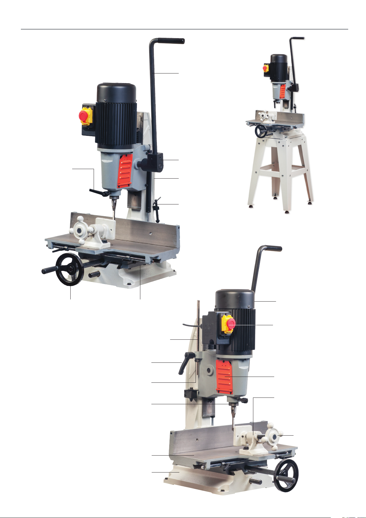
ILLUSTRATION AND PARTS DESCRIPTION
Operating lever
Chisel lift & shift
clamping handle
Table operating wheel
Transverse gib strip adjusting
screws and locking nuts
Depth setting bar
Lever coupling
Head stock
support column
Chuck key
AT25BM Morticer
with optional stand
Motor
NVR switch with
emergency stop
shroud
Depth setting bar clamping handle
Depth stop ring collar
Chisel mounting ange
Table
Cast iron base
Chuck access door
Table clamp
Clamp wheel
9
Page 10
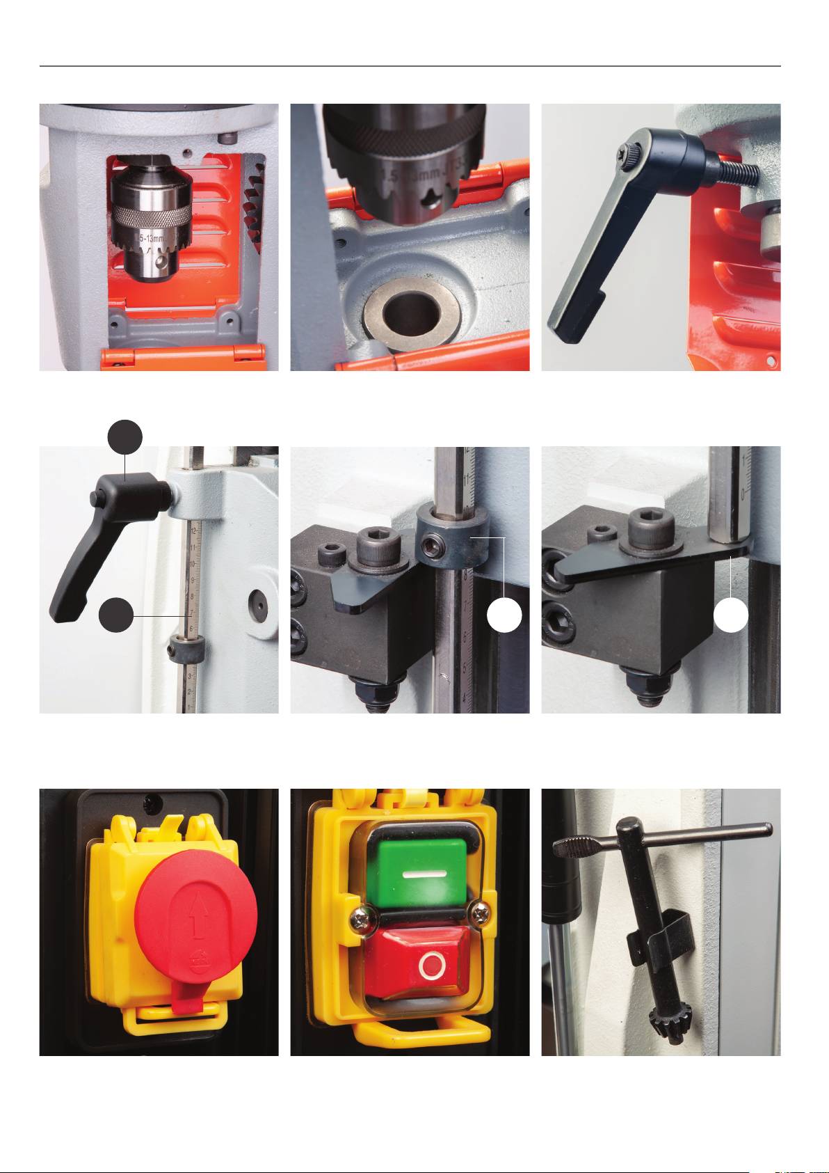
ILLUSTRATION AND PARTS DESCRIPTION
1.5-13mm Chuck Bush adaptor Mortice chisel clamping handle
A
B
Clamping handle (A)
Depth setting scale bar (B)
C D
Depth stop ring collar (C) Depth stop plate (D)
NVR Emergency stop shroud NVR ON/OFF switch Chuck key storage clip
10
Page 11
E
ILLUSTRATION AND PARTS DESCRIPTION
F
E
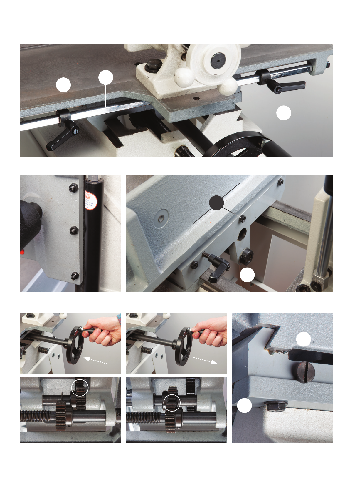
Two collar stops with lift & shift handles (E), Collar stop bar (F)
Gib strip adjusting grub
screws and locking nuts
G
H
Table front to back adjustment grub screws and locking nuts (G)
Table left to right clamping handle (H)
I
Push operating wheel to engage the
gears to move the table from left to right
Pull wheel out to engage the lead
screw to move the table front and back
11
J
Table left to right gib strip adjusting
screw (I) and locking nuts (J)
Page 12
SETTING UP THE MORTICER
Initial Setup
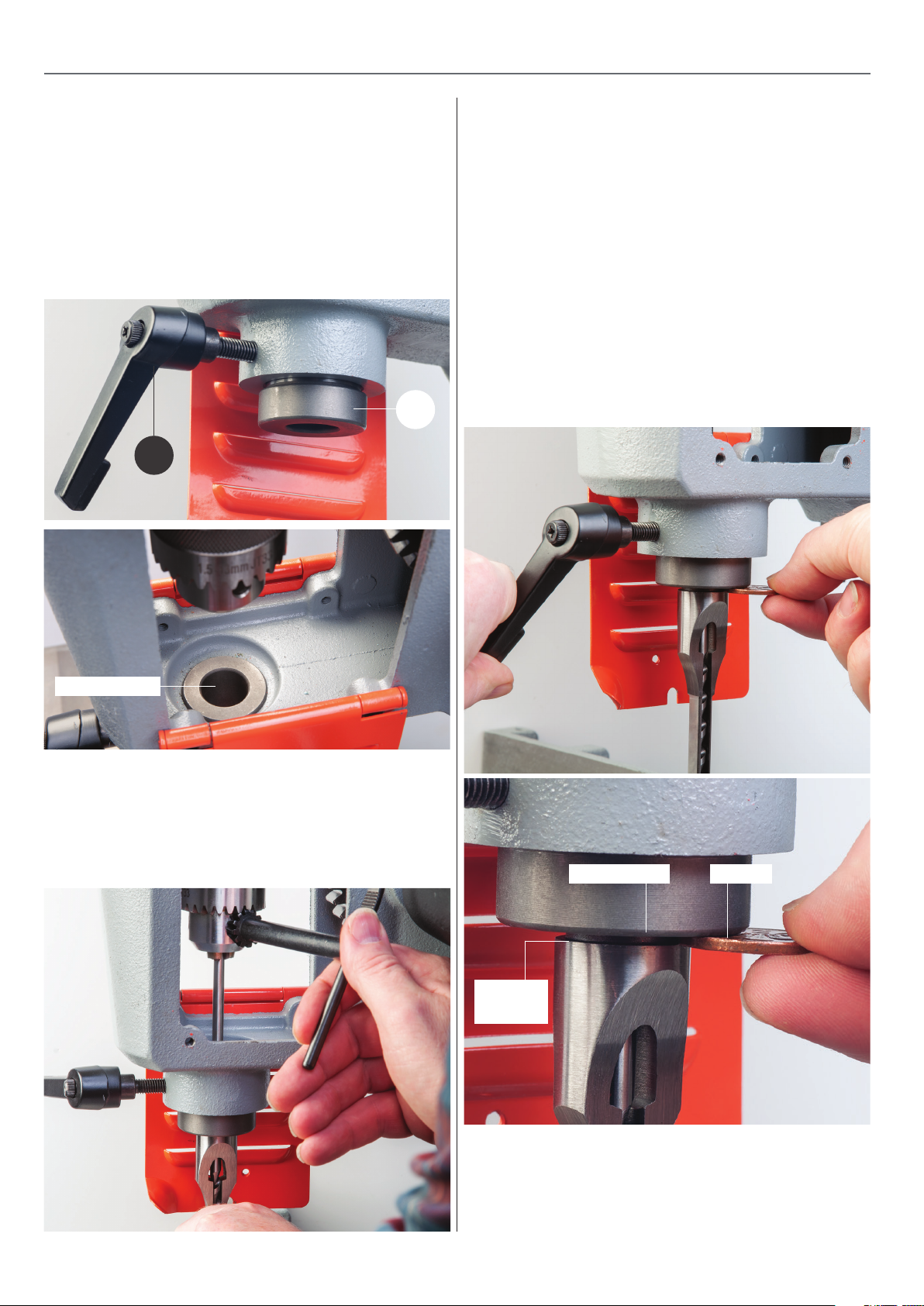
NOTE: Select the correct bush adaptor (C) 13/16” or 3/4” for the
shank of the required chisel and introduce it into the underside
of the chisel head stock. Push the bush up as far as it will go,
at the same time lining up the hole in the side of the bush and
screwing in the clamping handle (H), far enough to prevent the
bush from falling out, see g 15-16.
Fig 15-16
Setting the Chisel Auger Clearance
The old rule of thumb for chisel auger clearance was known as
“the one penny width”. This was achieved by introducing a
penny between the locating shoulder of the chisel and the
adaptor face, with the auger locked in place and with the chisel
pulled hard down on the auger. The penny was then removed
and the chisel pushed up to the adaptor face and, locked in
place. This established the “one penny width” between the
chisel and the auger, which for general timbers and mortice
sizes is quite adequate, see gs 18-19. Traditional morticers
normally had a cross pin in the auger mounting mandrel, to
prevent the auger being pushed back up into the chisel. The
mounting method on the newer morticers is a chuck.
C
H
Fig 18-19
Bush adaptor
Introduce the chisel into the adaptor collar, press the auger bit
up into the chuck and tighten the chuck, see g 17, withdraw
the chuck key. Gently pinch the chisel in place by nipping tight
the clamping handle (H).
Fig 17
PennyAdaptor face
Locating
shoulder
It is well worth taking the extra time and care to prepare your
augers to give the correct ‘reach’ when ‘bottomed’ out in the
chuck. This will prevent the auger being pushed back towards
the chisel and altering the clearance setting, see g 20.
12
Page 13
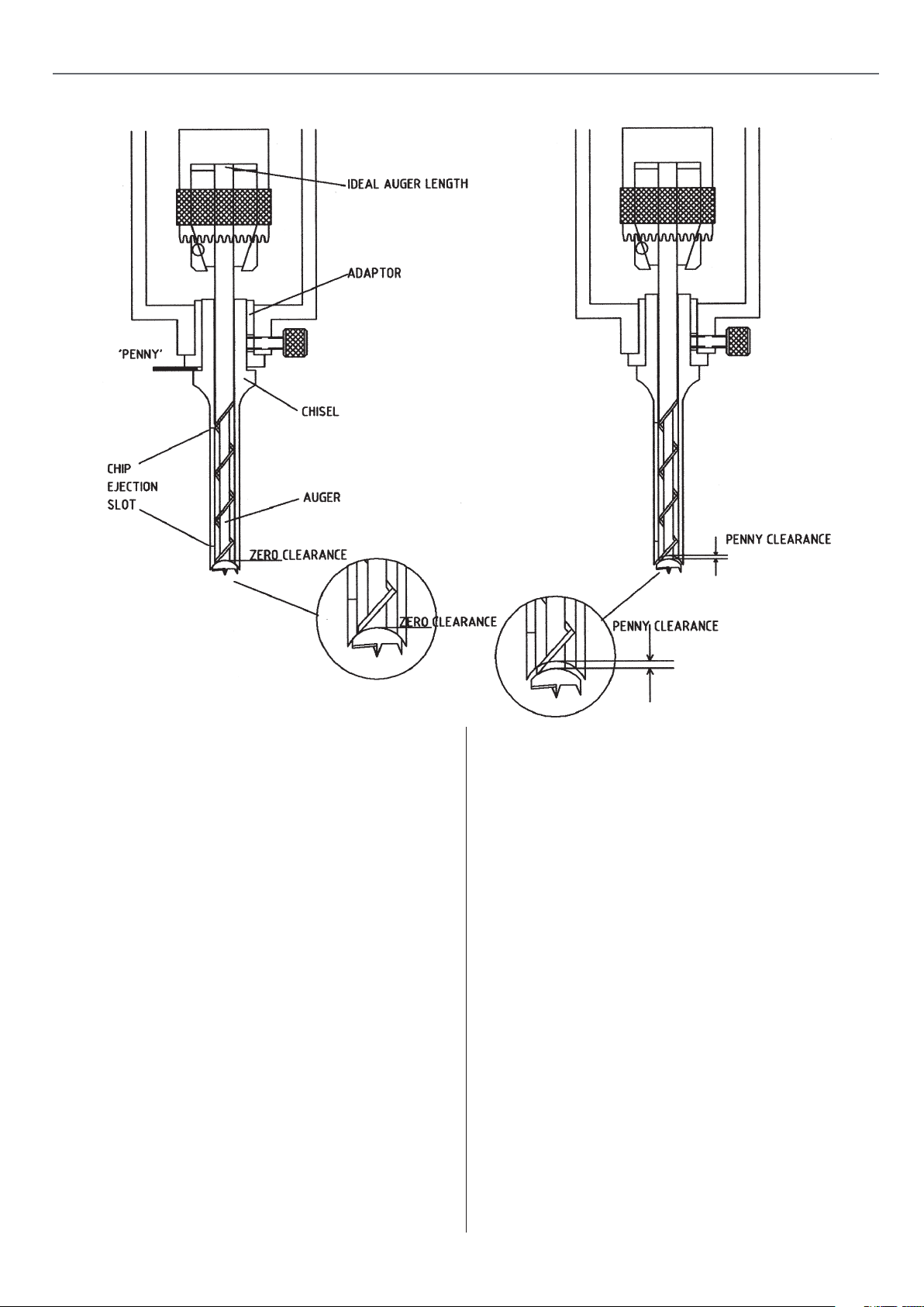
Fig 20
SETTING UP THE MORTICER
General Notes
The mortice will generate a lot of ‘grip’ on the chisel, especially
the rst cut, or if the timber is a little green. Make sure you use
the table clamp assembly to help control the timber during the
raise operation of the morticer.
Setting the Chisel Square
When the chisel is tightened in the machine it must normally
be square to the back fence. The easiest way to achieve this is
to bring the head stock down to bring the chisel as close to the
table as possible, set a square against the back fence and set
the side of the chisel against the square and clamp tight.
(Remember to have the chip ejection slot in the chisel to the
side from which you will cut the mortice).
Quick Setting of the Mortice Depth
Put a mark on an easily accessible end of the work piece to be
mortised, at the depth you require. Pull the head stock down,
and put the end of the timber against the chisel, position the
head stock so that the chisel points or the auger point are at
the depth required, raise the depth stop collar to the under
side of the head stock and tighten gently. Recheck the depth
of the chisel point, if it is satisfactory tighten securely, if not it
can be gently ‘nudged’ down the column with the head stock,
then tighten. Reposition the operating handle to give the most
comfortable position and purchase on the lever, over the full
distance of the movement you have just set.
Head Stock Rise Adjustment
Coupled with the depth stop on the same assembly is the
head stock rise limiter. This limits the rise of the head stock /
chisel to a convenient distance above the work by the use of a
locking collar positioned above the stop nger on the side of
the head stock. The travel of this assembly is then restricted to
your chosen setting rather than having to return it to the top of
the slide each time.
-
13
Page 14
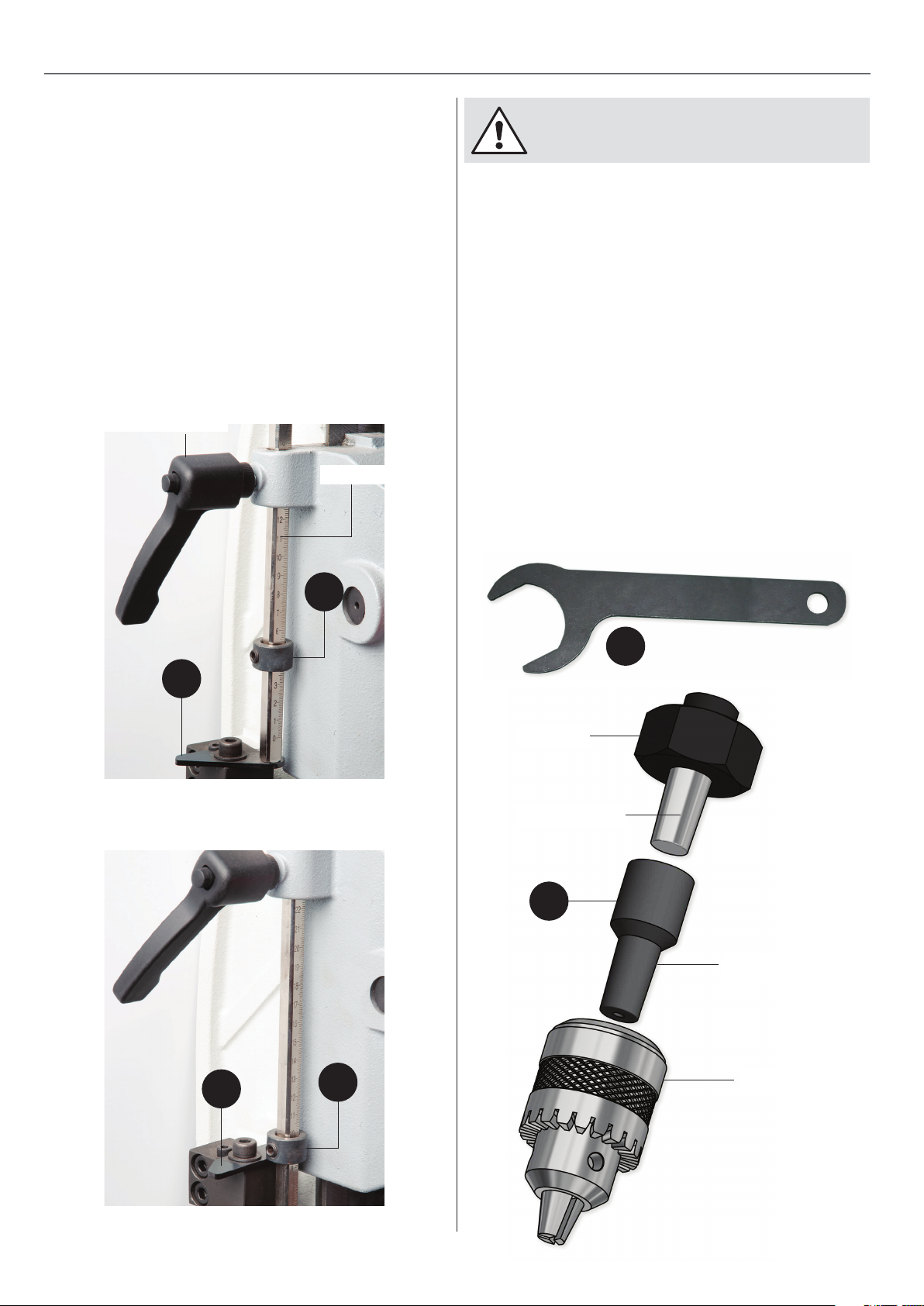
SETTING UP THE MORTICER
Setting the Chisel Depth
The chisel depth can be set to give two depth settings; the rst
method is adjusting the setting bar and the second is to adjust
the ring collar clamp (B). First method, with the stop plate (A)
set in the angled position. Set the bar depth then lower the
head stock so the bar rests on top of the stop plate (A) giving
the rst depth, see g 21.
The second depth can also be set by repositioning the stop
plate (A) in the square position. Allowing the setting bar to
drop so the ring collar clamp (B) which rests against the stop
plate (A) giving the second depth, see g 22.
Fig 21
Depth setting bar clamp
Depth setting bar
WARNING!! DISCONNECT THE MORTICER FROM THE
MAINS SUPPLY BEFORE CONTINUING!
Chuck Extension
To increase the chuck’s travel, the morticer comes with a ‘chuck
extension’ (I). This ts between the motor spindle and the
chuck. To t the extension, rst open the chuck access doors.
Using the spanner (D) hold the chuck in place, turn the large
nut downwards on the spindle to push the chuck assembly o
the tapered spindle. Clean the spindle to remove any build up
of debris.
Note: before tting the extension, wind the large nut back
up the spindle.
Insert the extension (I) up over the motor spindle, then replace
the chuck by inserting it over its extension. Place a piece of
wood against the chuck and tap rmly home using a high face
mallet. Assemble the chisel as described on page 12 and close
both chuck doors. Continue with operation.
Fig 22
B
D
A
Large nut
Motor spindle
I
Chuck extension
A
B
1.5-13mm Chuck
14
Page 15
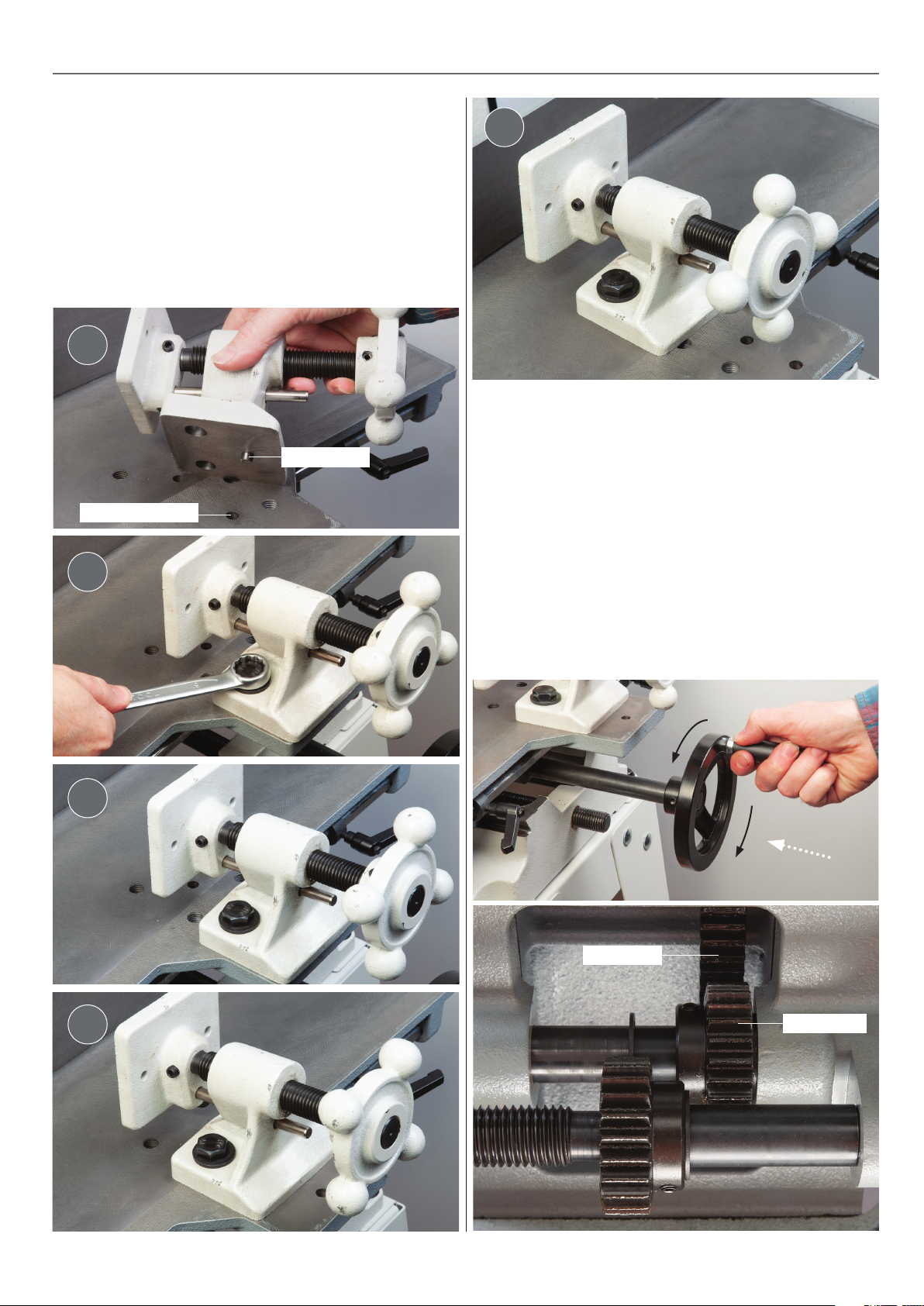
Table Clamp
The table clamp can be adjusted to accommodate dierent
sizes of timber using the pre-drilled holes in the table. Using
a spanner remove the two bolts and washers and place safely
aside. Re-position the clamp assembly to the desired position
and replace the two bolts and washers and tighten, see gs
24-25-26-27-28.
Fig 24-25-26-27-28
1
SETTING UP THE MORTICER
5
Adjusting the Table
Locating pin hole
2
3
Locating pin
The work table can be adjusted from back to front and from left
to right by operating the main control wheel to the front of the
morticer.
Left to Right Movement
Push the operating wheel forward to engage the drive gear into
the table rack thus enabling the table to move from left to right,
see gs 29-30.
Fig 29-30
4
15
Table rack
Drive gear
Continues over...
Page 16
SETTING UP THE MORTICER
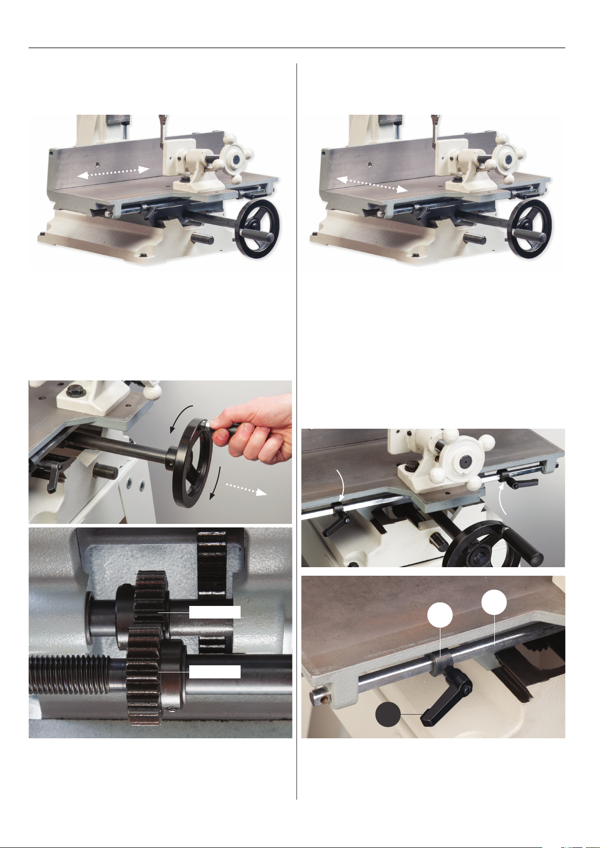
Left to Right Movement Back to Front Movement
Front to Back Movement
Pull the wheel out to engage the drive gear into the lead screw
thus enabling the table to move from front to back, see gs
31-32.
Fig 31-32
Table Distance Stops
To the front of the work table there are two collar stops to set
the required distance for repetitive work.
Loosen the collar clamping handle (A) and slide the collar
(B) along the collar stop bar (C) until the required distance is
reached then re-tighten the handle to lock the collar in position. Repeat for the other collar, see gs 33-34.
Fig 33-34
Drive gear
Table rack
C
B
A
16
Page 17
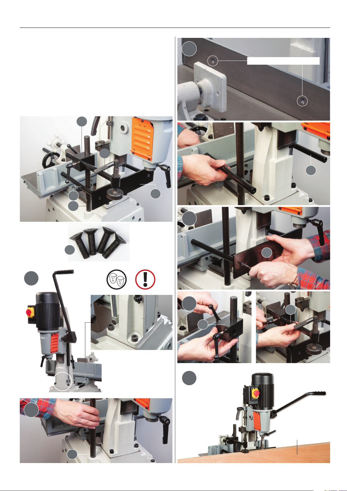
Door Mortice Kit
Code 105645
ACCESSORIES
3
This attachment allows the cutting of door lock mortices etc,
whilst holding the door rmly. The column/headstock on the
morticer swivels 180° to swing the mortice chisel over the door.
With the morticer mounted on its optional oor stand, a full
1metre wide door will t into the attachment. Obviously, when
the morticer is bench mounted this width may vary. Easy to t,
and with an adjustable door clamp.
R
S
T
V
U
Countersink mounting holes
T
4
1
2
X
With assistence turn the
morticer head assembly
around by removing the
four Hex bolts/washers
V
5
S
R
6
U
Door
17
Page 18
ACCESSORIES
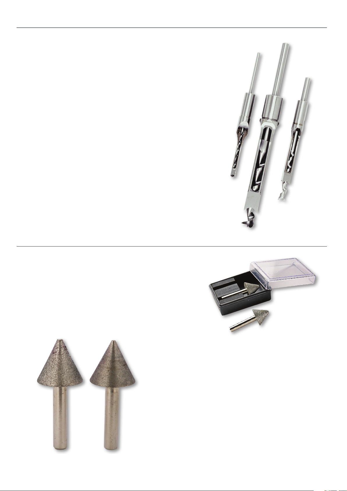
Morticing Chisels Introduction
Types of Chisel
The Japanese pattern has a point on the end of the bit and one cutting spur and
spiral for rapid chip clearance. The single spur is easy to sharpen and cuts evenly
and fast, even in the hardest of timbers.
Whatever the choice, the chisels need to be installed carefully if good results are
to be achieved.
Installation
The chisel needs to be installed square to the back fence. The other important
adjustment is to get the correct clearance between the cutting edge of the auger
and the conical recess in the base of the chisel; this will ensure that there is both
sucient support for the auger in the chisel and adequate space for chip clearance. One convenient way to achieve this is to install in position with a spacer
(such as a two pence coin) between the collar of the chisel and the locating face
on the machine, then bring the bit up so that the cutting part is hard against the
base of the chisel and then tighten up the shank of the bit in the chuck. The spac
er is then removed, the chisel moved up to its correct position andre-tightened.
Sharpening
Sharpening of the cutting spur is best achieved with a at needle le whilst the
chisels are best sharpened with the special piloted reamers.
-
Diamond Cone Mortice Chisel Sharpener
Sharpening a mortice chisel signicantly improves
performance. We can recommend this pair of specially made
diamond coated cones for most Taiwanese and Japanese
mortice chisels, and Veritas square hole punches. A coarse grit
cone gives an initial grind, followed by a ner honing cone to
create a sharp even edge.
Code: 502458
Instructions
Use the cones in a drill press or your morticer if you have a
chuck adaptor (a handheld drill is neither suitable nor safe).
Clamp the bit vertically and securely, or drill a hole in a block of
wood the same diameter as the chisel’s shank. The chisel must
be held rmly and perpendicular.
Fasten the coarse cone in the chuck and align it with the chisel
so it centres exactly in the end of the chisel, do this BEFORE
switching on. Running at low speed (150 to 250rpm), gently
lower the cone until it just makes contact with the mortice
bit. Carefully grind until you obtain a clean surface around the
entire bevel. Replace it with the 350-grit cone and repeat the
process, lightly honing the inside bevel. Use a ne at stone lap
the sides of the bit to remove any burrs.
18
Page 19
ACCESSORIES
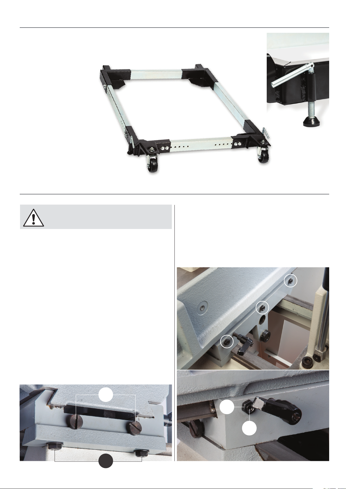
Axminster Heavy Duty Mobile Base
Our heavy duty mobile base
has two xed wheels at the
rear and features two castoring
wheels at the front. It is a practi
cal method for manoeuvring
heavy machines into position
safely and with ease. Maximum
total load is 540kg and the size
limits are 460mm x 620mm
minimum, up to 720mm x
850mm
maximum.
-
Code: 105072
MAINTENANCE
WARNING!! DISCONNECT THE MORTICER FROM THE
MAINS SUPPLY BEFORE CONTINUING!
Table and Head Stock Adjustment
After long periods of use, if you notice a degree of side play
developing on both the table and head stock, you will need to
adjust the gib strip screws until the slide play is eliminated.
Table Adjustment Left to Right
To adjust the left to right movement slacken the two Hex
locking bolts (A) beneath the right hand side of the table then
very carefully adjust the two gib strip screws (B), see g 35.
NOTE: make small adjustments, turning the operating wheel
until the table slides smoothly across, but not too much
causing the table to tighten or jam.
When you feel the slide play has been eliminated, tighten
the two locking Hex bolts (A) to secure the setting.
Fig 35
Table Adjustment Front to Back
To adjust the front to back movement slacken the three locking
nuts (C), to the rear of the table, then using a Hex key adjust
the three gib strip grub screws (D) until the side play has been
eliminated. Tighten the locking nuts (C) to secure the setting,
see gs 36-37.
Fig 36-37
B
A
C
D
19
Page 20
MAINTENANCE
Head Stock Adjustment
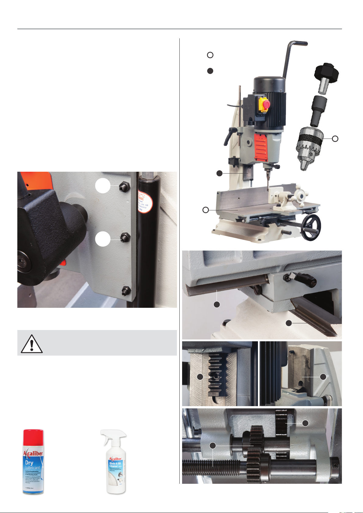
If there is sucient play happening in the head stock
assembly, loosen the three locking nuts (E) to the side of the
head stock column and carefully adjust the gib strip grub
screws (F), see gs 38.
NOTE: make small adjustments, pulling the operating
lever down until the head stock slides smoothly up and
down the column, but not too much causing the head
stock to tighten or jam.
When you feel the slide play has been eliminated, tighten the
locking nuts (E) on the column to secure the setting.
Fig 38
E
General Maintenance
Light Lubricate
Lubricate
F
General Maintenance
WARNING!! DISCONNECT THE MORTICER FROM
THE MAINS SUPPLY BEFORE CONTINUING!
To ensure optimum performance from your morticer routine
cleaning and lubrication is required.
After long periods of use, wood and resin deposits will build up
on the table and the rack and pinion gears. Clean all surfaces
using “Axcaliber Blade and Bit Cleaner Code 104736” then apply
a light application of lubricant to all moving parts using
“Axcaliber Dry Lubricant Code 503468”.
Code: 104736Code: 503468
20
Page 21
MAINTENANCE
Introduction
Chisels and bits should be kept sharp for best performance; a
discoloured tip is usually a sign of excessive heat caused by a
blunt auger and/or chisel.
Bits are best sharpened with a small le and chisels with the
special mortice chisel sharpeners, see our catalogue or visit our
website at axminster.co.uk
Burrs can be removed from the sides of the chisel on a ne
oilstone or waterstone but great care must be taken not to
taper the chisel as this will cause the chisel to jam in the timber.
Chisel Abrasion
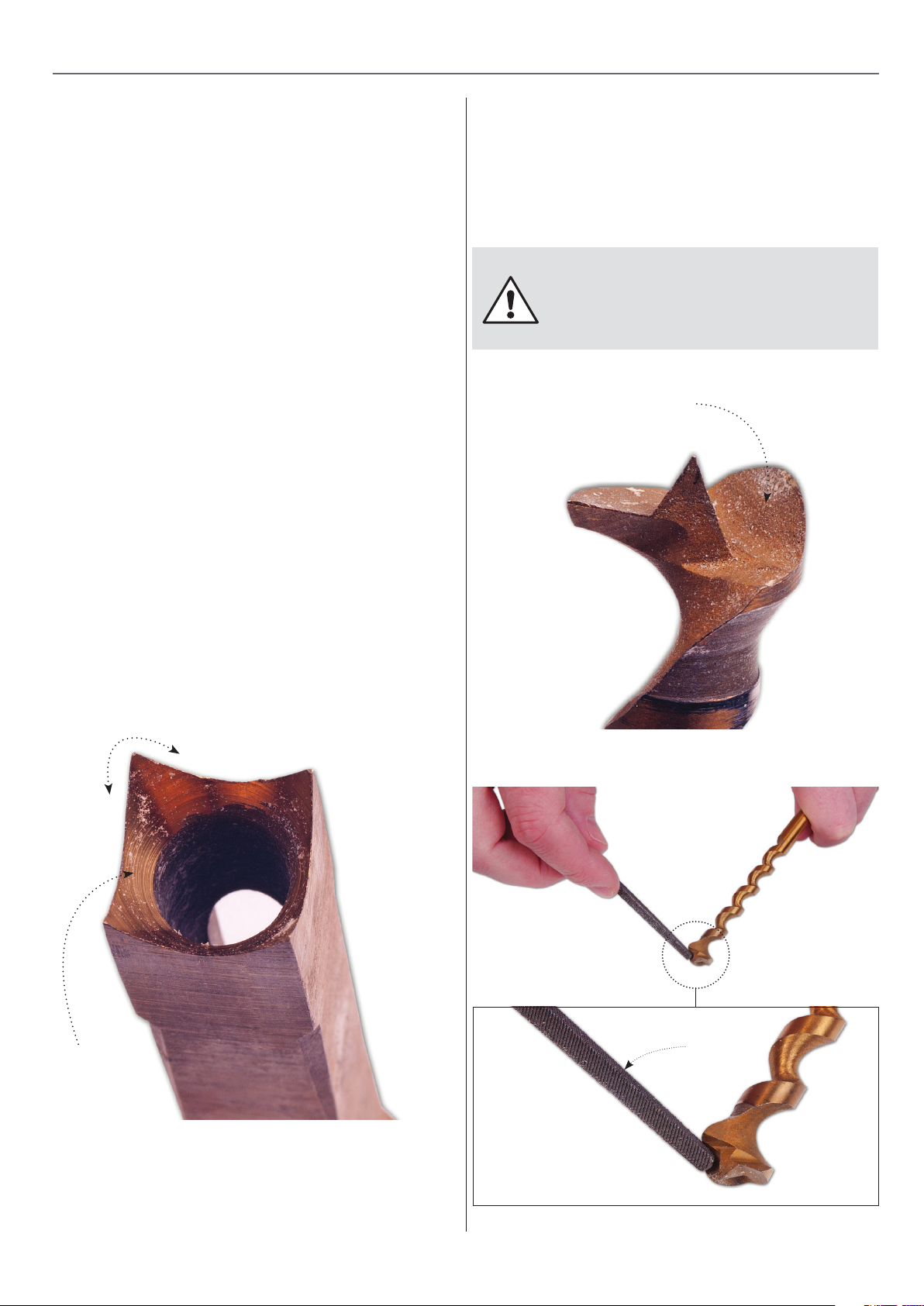
Look into the hollow of the chisel and check around the
corners for signs of dulled or rounded corners, see g 39. If
there are any deviations in the chisel we recommend using
the multi- ute conical reamer sharpening set, code 700173
with the appropriate size pilot piece, just a few turns removes
a tiny amount of metal from the chisel’s internal bevel.
When abrasion occurs to the extent that the chisel bit tip
becomes thin and liable to break, it is advisable to replace it
with a new one.
Sharpening Chisel Auger Bit
A well sharpened auger bit will cut more eciently, passing
easily through the twist and being ejected through the slot in
the side of the chisel. Sharpen the spur on the auger bit using
a small square or at le and sharpen the inside only, see gs
40-41.
WARNING!! DO NOT SHARPEN, STONE OR GRIND
THE BIT ON THE OUTSIDE WHICH WILL REDUCE ITS
DIAMETER CAUSING WOOD SHAVINGS TO BUILD UP
INSIDE THE CHISEL!
Inside of Spur
Fig 40
Fig 39
Square corner
Bevelled area
Fig 41
File
21
Page 22

TROUBLESHOOTING
Symptom Possible Causes Solutions
Morticer will not start
Overload kicks out frequently
Bit does not come
up to full speed
Morticer makes
unsatisfactory cuts
1. Fuse blown or circuit breaker
tripped.
2. Cord damaged. Replace the power cord by a qualied
1. Extension cord too light or too long. 1. Replace with adequate size cord.
2. Chisel and bit in poor condition
(dull or broken).
3. Timber is too wet. 3. Dry timber before cutting.
1. Extension cord too light or too long. 1. Replace with adequate size cord.
2. Low current. 2. Consult a qualied electrician.
3. Motor not wired for correct voltage. 3. Check motor name plate for
1. Dull hollow square chisel and bit. 1. Sharpen or replace the chisel and
Replace fuse or reset circuit breaker
electrician.
2. Clean or replace the chisel and bit.
correct wiring or consult a qualied
electrician.
bit.
The work starts to burn
The drill bit is down drilling
2. Gum or pitch on the chisel and bit. 2. Remove the chisel and bit and clean
using “Axcaliber Blade and Bit
Cleaner Code 951145” .
3. Gum or pitch on the worktable or
fence causing an un-square cut
4. The chisel and bit was not correctly
set.
1. Dull chisel and bit. 1. Sharpen or replace the chisel and bit.
2. The bit has worn out or is broken. 2. Replace the worn bit with a new one.
1. The bit is worn out or broken. 1. Replace the worn bit with a new
2. The bit is not sharp enough. 2. Sharpen the bit.
3. The drill bit has come loose in
the chuck.
3. Clean the worktable and fence as
described above.
4. Make sure the entire assembly is
correctly held with proper clearance
of 2mm-5mm.
one.
3. Tighten the drill chuck with the key
provided.
The machine vibrates
1. Damaged chisel bit. 1. Replace the damaged bit with a
new one.
2. Stand on uneven oor. 2. Reposition on at level surface.
Fasten to oor if possible.
22
Page 23
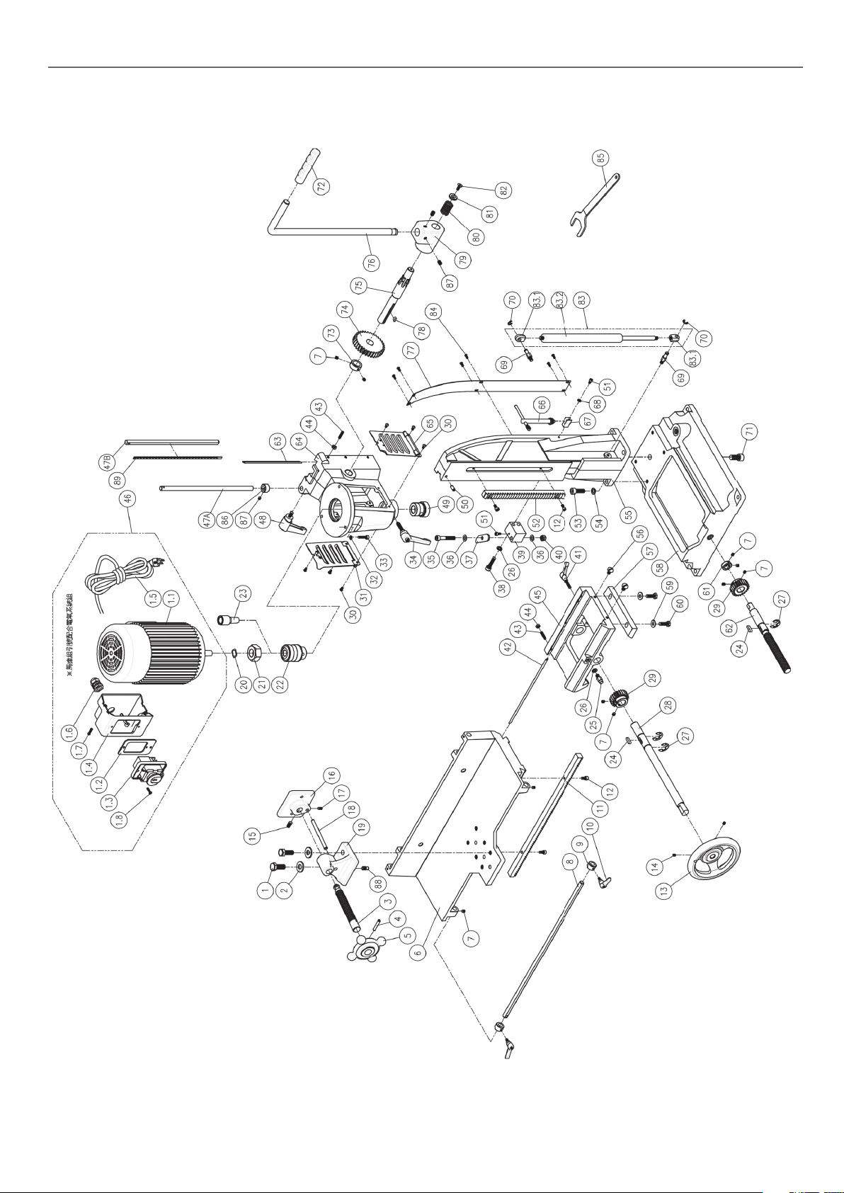
EXPLODED DIAGRAMSLISTS
AP25BM Morticer
Code 107638
R2310-B1
23
Page 24

EXPLODED DIAGRAMSLISTS
No Item No Item Specication Qty
1 50101047 Hex. Screw M12x1.75Px30L 2
2 50351062 Flat Washer 1 2”x28x3t 2
3 23031035 Lead Screw 1
4 50602013 Spring Pin 6x36L 1
5 23031038 Handle Wheel 1
6 23101003 Main Table 1
7 50103054 Set Screw M6x1.0Px6L 10
8 23031033 Setting Bar 1
9 23041037 Collar Stop M6x1.0P 2
10 50114057 Universal Handle M6x1.0P*10L 2
11 23041027 Rack 1
12 50102005 Cap Screw M6*1.0Px12L 4
13 38021007 Handle Wheel 1
14 50153019 Set Screw 5/16”-18UNx5/8”L 2
15 50103007 Set Screw M8x1.25Px16L 1
16 23031034 Clamp plate 1
17 50103015 Set Screw M6x1.0Px10L 1
18 23031036 Clamp Rod 1
19 23101020 Clamp Base 1
20 50304002 Wave Washer BWW-16 1
21 23041048 Chuck Release Nut 1
22 23041034 Chuck 1
23 23041064 Chuck Extension
24 50604048 Key 6x6x20L 2
25 23101009 Setting Block 1
26 50302008 Spring Washer M8 3
27 50403006 E Ring ETW-15 3
28 23101014 Shaft 1
29 23101015 Gear 2
30 50104047 Round Head
31 23041032 Left Side Cover 1
32 50302007 Spring Washer M6 3
33 50102008 Cap Screw M6x1.0Px25L 3
34 50114056 Universal Handle M8x1.25Px30L 1
35 50102015 Cap Screw M8x1.25Px50Lx30L 1
36 50301102 Flat Washer 8.2x16xlt 2
37 23101011 Stop Plate 1
38 50102014 Cap Screw M8x1.25Px35L 2
39 23101010 Lift Setting Block 1
40 50202004 Nylon Nut M8x1.25P 1
41 50114046 Universal Handle M6x1.0Px28L 1
42 23101007 Gib 1
43 50103053 Set Screw M6x1.0Px25L 6
44 50201013 Hex. Nut M6x1.0P 6
45 23101002 Base, Middle 1
Adaptor
M5x0.8Px8L 6
Phillips Screw
1
46 23041505 Motor 1
47 23101017 Setting Rod 1
48 50114005 Universal Handle M8x1.25Px15L 1
49 23041042 Bushing 1
50 50602032 Spring Pin 6x16L 1
51 50102003 Cap Screw M5x0.8Px10L 2
52 23041014 Rack 1
53 50102016 Cap Screw M10x1.5Px30L 4
54 50302010 Spring Washer M10 4
55 23101005 Column 1
56 23031015 Screw 2
57 23101006 Gib 1
58 23101001 Fixed Base 1
59 50301091 Flat Washer 8.5x20x1.5t 2
60 50101034 Hex. Screw M8x1.25Px25L 2
61 23101013 Fixed Collar 1
62 23101012 Lead Screw 1
63 23041013 Gib 1
64 23101004 Headstock 1
65 23041033 Right Cover 1
66 23041063 Chuck Key 1
67 23011077 Chuck Key Holder 1
68 50302006 Spring Washer M5 1
69 23041052 Upper Cylinder
70 50403001 E Ring ETW-7 2
71 50102027 Cap Screw M12x1.75Px30L 1
72 23041030 Handle Grip 1
73 23041061 Collar 1
74 23011013 Gear 1
75 23041022 Gear Shaft 1
76 23101019 Handle 1
77 23101008 Back Cover 1
78 50604005 Key 5x5x12L 1
79 23101018 Handle Hub 1
80 23041047 Spring 1
81 23041049 Washer 1
82 50108004 Socket Head Flat
83 23041101 Hydraulic Cylinder 1
84 50104057 Round Head
85 33050021 Wrench 1
86 23101022 Setting Block M8x1.25P 1
87 50103073 Set Screw M8x1.25Px8L 3
88 23101021 Pin 1
89 23101016 Scale 1
Fitting
M6x1.0Px16L 1
Screw
M4x0.7Px10L 6
Phillips Screw
2
24
Page 25
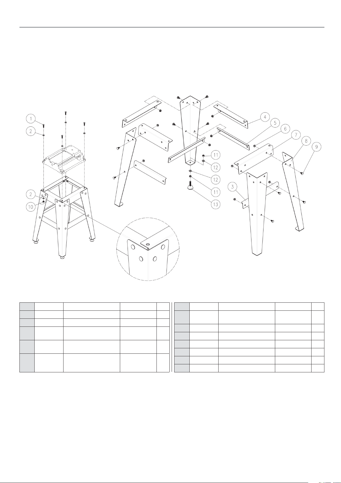
EXPLODED DIAGRAMSLISTS
Optional AP25BM Stand
Code 105645
R2310-B2
No Item No Item Specication Qty
1 50101046 Hex. Screw M8x1.25Px30L 4
2 50301091 Flat Washer 8.5x20x1.5t 8
3 23102005 Lower Support, Left &
Right
4 23102002 Upper Support, Front &
Rear
5 23102004 Lower Support, Front &
Rear
2
2
2
6 50206002 Hex. Nut with Collar M8x1.25P 24
7 23102003 Upper Support, Left &
Right
8 23102001 Main Stand Support 4
9 50110014 Carriage Bolt M8x1.25Px16L 24
10 50201019 Hex. Nut M8x1.25P 4
11 50201016 Hex. Nut M10x1.5P 8
12 50301085 Flat Washer 10x20x2.0t 8
13 71011017 Adjustment Screw 4
25
2
Page 26
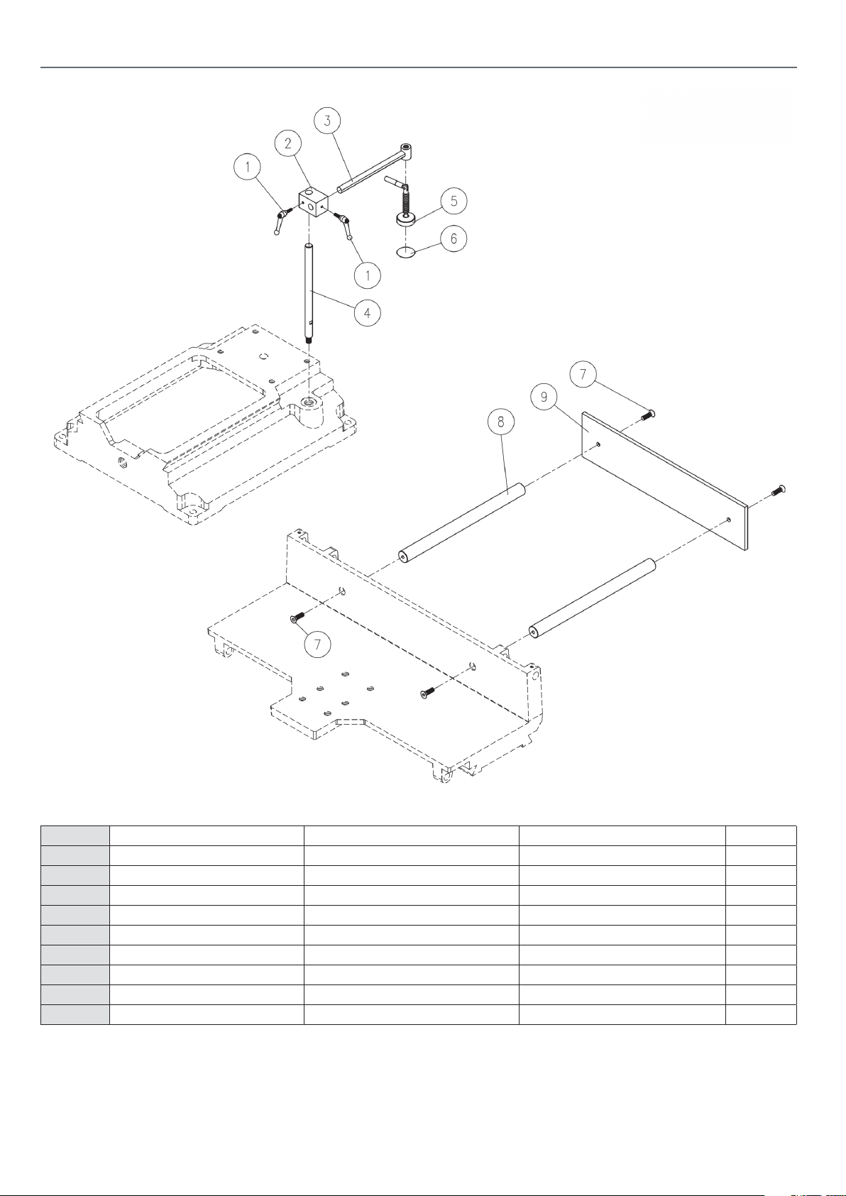
EXPLODED DIAGRAMSLISTS
Optional Door Mortice Kit
Code 105646
R2310-B4
No Item No Item Specication Qty
1 42011101 Universal Handle 2
2 23045005 Fix Shaft Bracket 1
3 23045003 Hold Down Shaft 1
4 23045006 Fix Shaft 1
5 23045101 Hold Down 1
6 23045004 Abrasive 1
7 50108007 Hex. Pan Head Screw M6x1Px20L 4
8 23045002 Fix Shaft 2
9 23045001 Fence 1
26
Page 27
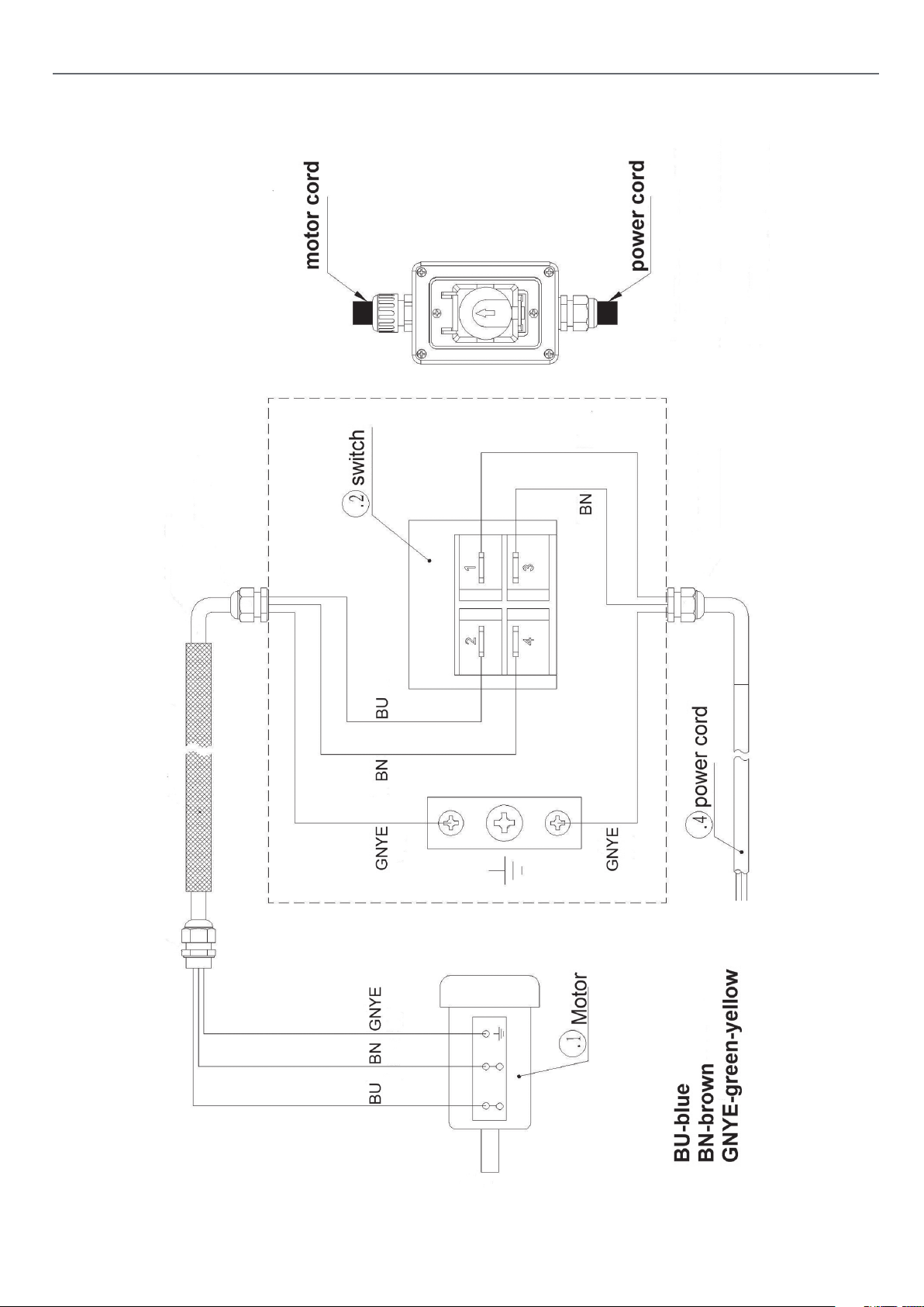
WIRING DIAGRAM
27
Page 28

The Axminster guarantee
Buy with confidence from Axminster!
So sure are we of the quality, we cover all parts and labour free of charge for three years!
For more information visit axminstertools.com/3years
The packaging is suitable for recycling.
Please dispose of it in a responsible manner.
EU Countries Only
Do not dispose of electric tools together with household waste material.
By law they must be collected and recycled separately.
Axminster Tools, Axminster Devon EX13 5PH
axminstertools.com
 Loading...