

Page 1
Code AP254SB: 108516
Code AP305SBD: 110642
Original Instructions
AP254SB Saw Bench &
AP305SBD Table Saw 230V
AP254SB
AP305SBD
AT: 10/7/2025
BOOK VERSION:
03
Page 2
INDEX OF CONTENTS
What’s in the box 02-03
Safety 04-05
Assembly 05-06-07-08-09-10-11
Set up / Levelling / Fine Tuning 12-13-14
General Use / Operation 15-16-17-18
Troubleshooting 19
Maintenance 19-20-21
Optional Accessories 22-23-24-25
Exploded Diagram/Parts Lists 26-27-28-29-30
Wiring Diagram 36
Declaration of Conformity 37-38
2022
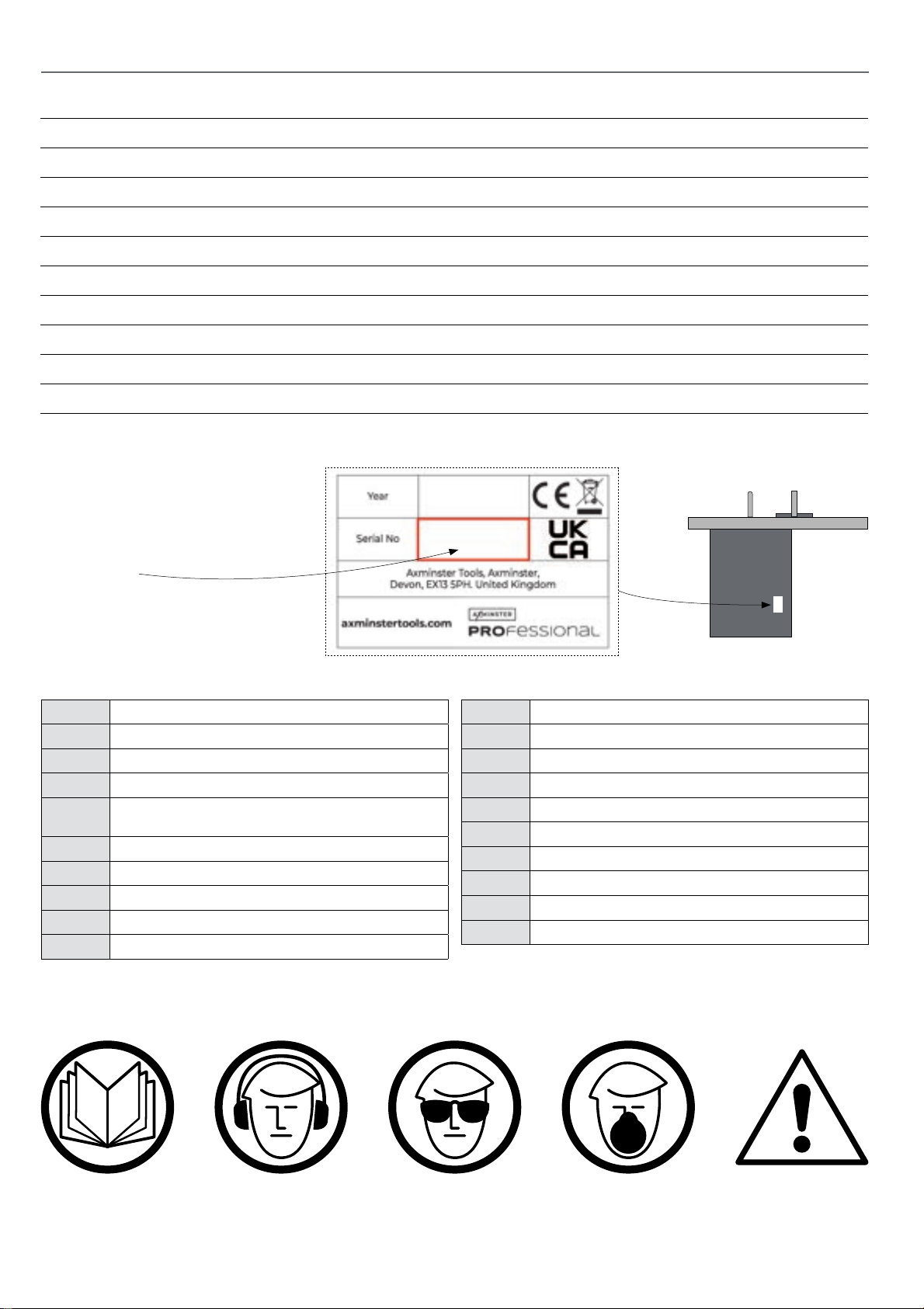
The machines Serial Number is
located on the specification label
as shown.
A Rip-Fence Assembly
B Front Fence Rail
C Rear Fence Rail
D High and Low Aluminium Sub Fence
E Cast iron extension tables,
2 with AP305SBS, 1 with AP254SB
F Rear Extension Table
G Rear Extension Table Angle Support Brackets
H Mitre Fence
I Push Stick
J Crown Guard
2003256
Rear View
K Riving Knife
L Flexible Hose Support Bracket + Fixings
M Four Hose Clips
N Dust Extraction Port
O Operating Handwheel Knobs
P 63mm Short Hose
Q 63mm Long Hose
R Tool Kit
S Bolt Pack
T Main Table Saw
The symbols below advise the correct safety procedures when using this machine.
Fully read manual
and safety instructions
before use
Ear protection
should be worn
Eye protection
should be worn
2
Dust mask
should be worn
HAZARD
Page 3
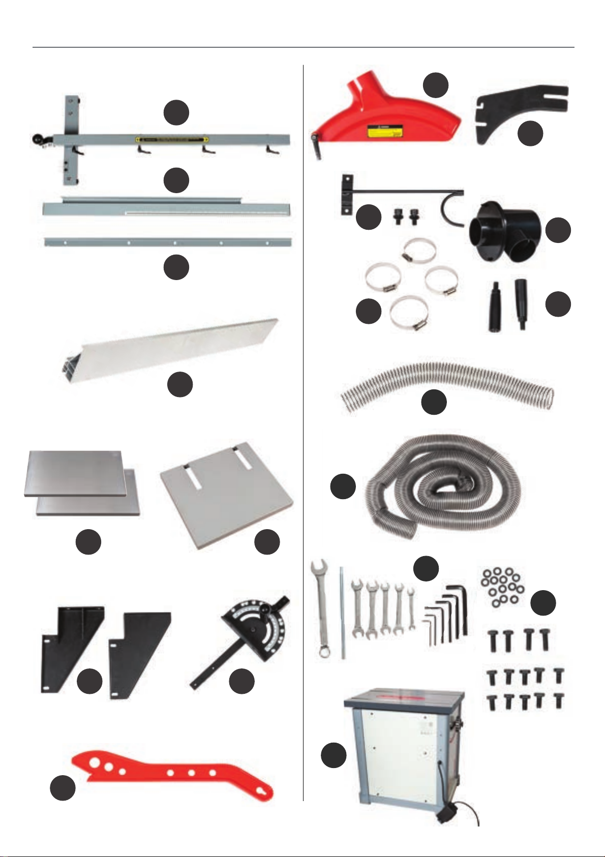
Fig A
WHAT’S IN THE BOX
J
A
K
Fig B
Fig C
B
C
D
L
M
Fig F
N
O
Fig H
P
Fig D
Fig E
E F
G H
T
Q
R
Fig I
S
I
3
Fig J
Page 4
SAFETY
The following is a list of safety precautions you must consider when using a Table saw:
ALWAYS REMEMBER TO DISCONNECT THE POWER TO THE TABLE SAW
WHEN MAKING REPAIRS OR ADJUSTING BLADES AND GUARDS.
ALWAYS REMEMBER TO READ THROUGH THE MACHINE INSTRUCTIONS SUPPLIED.
• Eye and ear protection are required when operating a
Table saw. Dust extraction & respiratory PPE are highly
recommended.
• Do not wear gloves, loose clothing, jewellery, or any
dangling objects when operating a Table saw.
• Do not allow children to operate the machine.
• At all times all guards must be in place and fully
operational. If a guard seems to be missing or
damaged, adjust, replace or repair immediately.
• A riving knife MUST be used at all times when
performing through cuts and must be positioned
correctly.
• Ensure that the Rip fence is correctly aligned to the
blade to help prevent the risk of timber kick back.
• Never perform “free hand” cuts, a rip fence or mitre
cross cut fence should always be used.
• Never pull the timber through the blade from the rear
of the machine, always push through from the front.
• Make sure the blade is not in contact with the material
when you start the saw.
• Never leave the machine unattended when it is running.
•Keep the table top & surrounding work area free from
excessive dust and debris to help prevent slipping or
tripping.
• Maintain a balanced stance at all times so that you do
not fall or lean against the blade or other moving parts.
Do not overreach or use excessive force to perform any
machine operation.
Kickback
• The most common accidents among table saw users,
according to statistics, can be linked to kickback, the
high-speed ejection of timber from the table saw that
can strike the operator. Kickback can also result in the
operator’s hands making contact with the blade.
Kickback Prevention
• Tips to avoid the most common causes of kickback:
• Disconnect the power to the Table saw when making
repairs or adjusting blades and guards.
• Hands and fingers must be kept clear of the blade,
always use push sticks when feeding smaller pieces into
the blade.
• Use only the recommended blade size and type for the
machine - see page (20) for recommendations.
• Ensure all blades are sharp and in good condition.
• Never cut pieces smaller than the table insert size.
• Long material should be supported at the same height
as the saw table.
• To avoid contact with a coasting blade, do not reach into
the cutting area until the blade comes to a full stop.
• Make sure the riving knife is always aligned with the
blade. A workpiece can bind or stop the flow of the cut
if the riving knife is misaligned, and result in kickback.
• Use a riving knife during every cut. The riving knife
maintains the kerf in the workpiece, which will reduce
the chance of kickback.
• Never attempt freehand cuts.
• The workpiece must be fed parallel to the blade,
otherwise kickback will likely occur. Always use the rip
fence or mitre gauge to support the workpiece.
• Make sure that the rip fence is parallel to the blade. If
not, the chances of kickback are very high. Take the time
to check and adjust the rip fence.
• Feed cuts through to completion. Anytime you stop
feeding a workpiece that is in the middle of a cut, the
chance of binding, resulting in kickback, is greatly
increased.
4
Page 5
Tips for Kickback Protection
SAFETY
Kickback can happen even if precautions are taken to
prevent it. Listed below are some tips to protect you if
kickback does occur:
• Stand to the side of the blade when cutting. An ejected
workpiece usually travels directly in front of the blade.
• Wear safety glasses or a face shield. Your eyes and face
are the most vulnerable part of your body.
More safety information can be found at: http://www.hse.gov.uk/pubns/wis16.pdf
• Never place your hand behind the blade & never pull the
timber through the cut. If kickback occurs, your hand will
be pulled into the blade.
• Use a push stick to keep your hands further away from
the moving blade. If a kickback occurs, the push stick will
most likely take the damage that your hand would have
received.
ASSEMBLY FOR SET UP LEVELLING FINE TUNING SEE PAGE 12
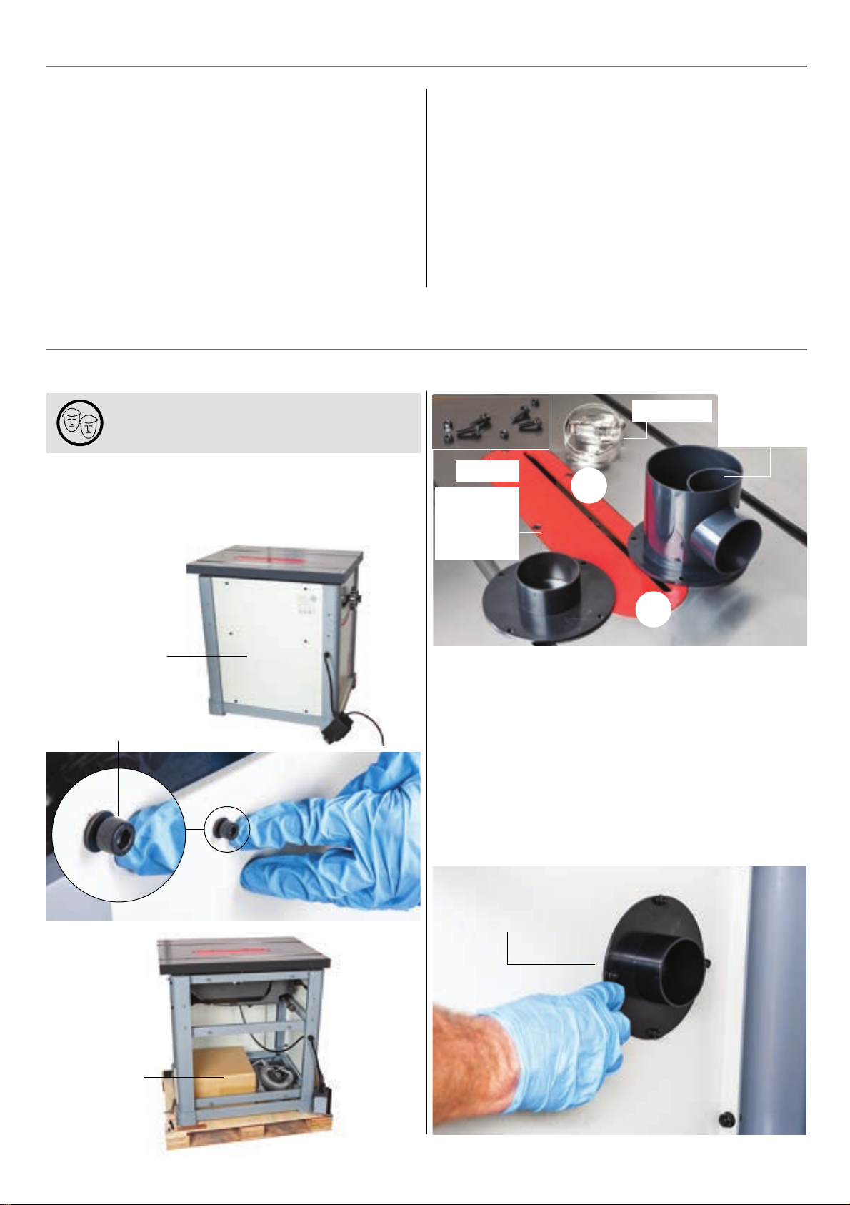
Fitting the Extraction Port
WARNING! THE MACHINE IS HEAVY ITS
ADVISED TO HAVE HELP.
1. Remove the left side panel by removing the six
caphead bolts / washers and place safely to one side.
Remove cardboard box and other items from within the
saw frame, see fig 01-02-03.
Fig 01-02-03
Fig 04
Fixings
63mm
Inner port
flange
spigot
M
Hose clips
100mm
Outer port
Spigot
Side panel
Caphead bolt & washer
N
2. Locate the ‘Dust Extraction Port’ assembly’, ( N ).
Remove the four screws and nuts from the extraction
port and separate the inner and outer parts, see fig 04.
3. Postion both parts over the extraction port hole to the
saws rear panel. NOTE: Fit the 100mm port spigot to the
outer side of the rear panel. Secure using the four screws
and nuts you removed eariler, see fig 05-06.
Fig 05-06
The 63mm flange
spigot is place inside
the cabinet.
Cardboard
box & other
parts
5
Continues over...
Page 6
ASSEMBLY
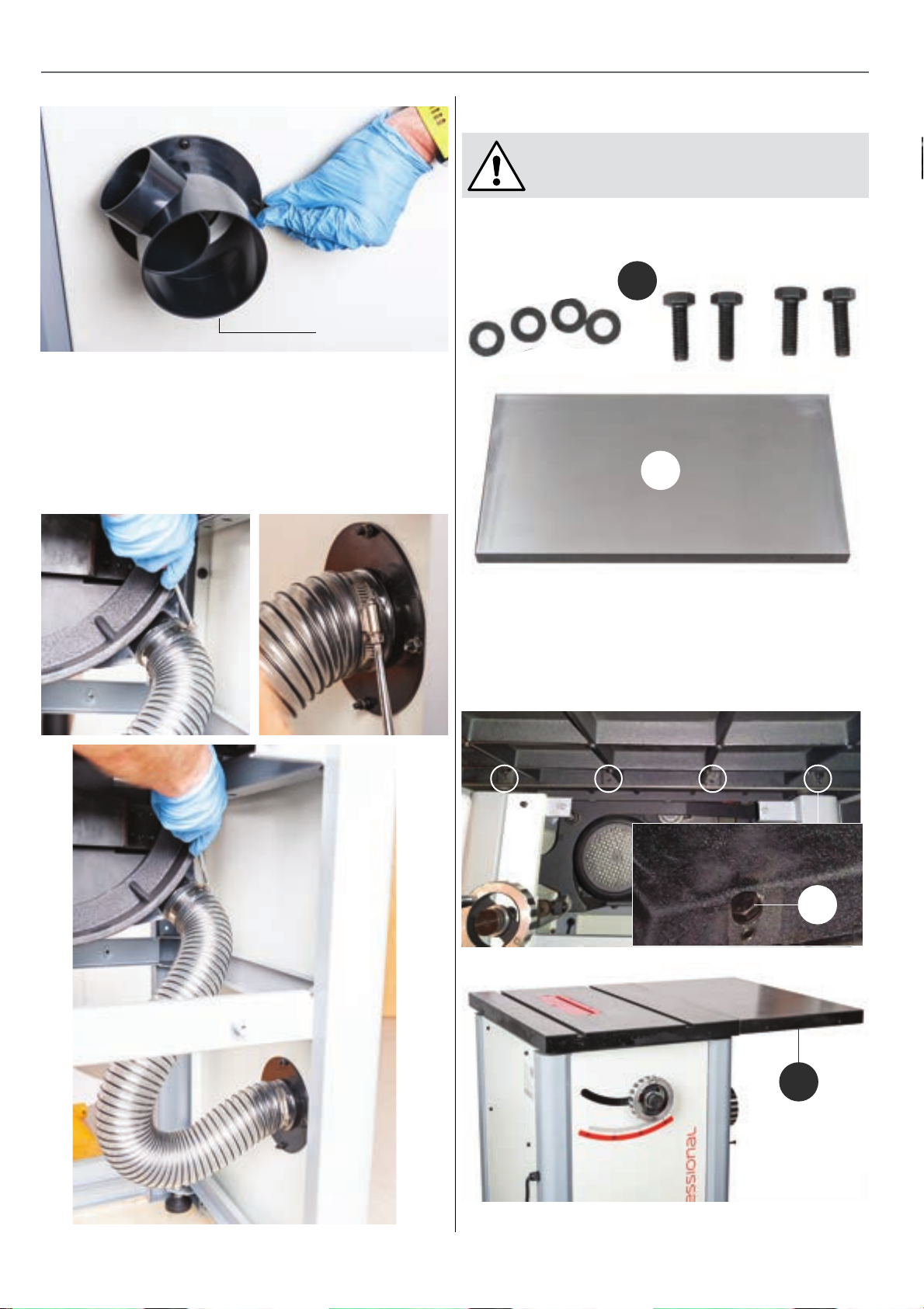
Fitting The Cast Iron Extension Tables
WARNING! WE ADVISE YOU GET ASSISTANCE
AS THE CAST IRON TABLE IS HEAVEY.
1. Locate The right hand extension table ( E ) and the four
long bolts / flat washers ( S ), see fig 10.
The 100mm spigot
placed on the outside
of the cabinet
4. Locate the short flexible hose, ( P ) and two hose clips
( M ). Place a clip over each end of the hose and fit the
hose over the saws dust housing outlets from inside the
main saw frame. Nip-up the retaining clips to secure the
hose in place, see fig 07-08-09.
Fig 07-08-09
Fig 10
S
E
2. Position the extension table, ( E ) against the side of the
main table, lineup the four threaded holes in both tables
and secure in position with the long bolts / washers ( S ),
see fig 11-12-13.
Fig 11-12-13
S
E
6
Page 7
ASSEMBLY
1
A
2
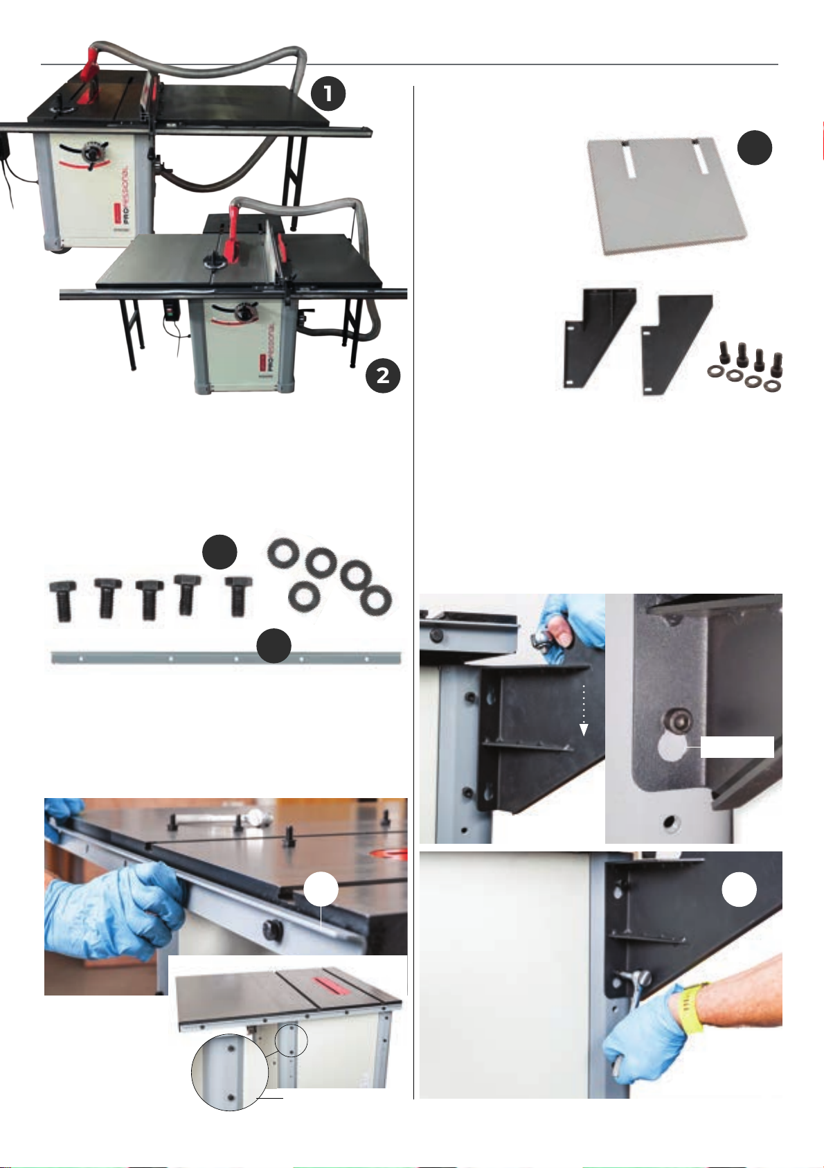
The cast iron extension tables can be fitted either both on
the right (1) or one left and one right (2). Fitting the support legs is highly recommended.
Fitting the Rear Fence Rail
1. Locate five short bolts / flat washers ( S ) and the rear
fence rail ( C ), see fig 14.
Fig 14
S
Fitting the Rear Table Extension Table
Fig 17
1. Locate the rear
extension table ( F ),
two angle support
brackets, four short
caphead bolts and four
flat washers ( G ), see
fig 17-18.
F
Fig 18
2. To the rear of the of
the cabinet there are
four threaded holes
on each support
column, with two
caphead bolts mounted into the two upper holes on each
side, see fig 16. Loosen the caphead bolts to give sufficient
clearence for the next step.
3. Locate the two angle support brackets ( G ). Lineup
the key slots in the right hand side bracket and lower the
bracket down over the two caphead bolts. Lightly tighten
the bolts to secure the bracket in place. Repeat for the
opposite side, see fig 19-20-21.
Fig 19-20
C
2. Position the rear fence rail ( C) to the rear of the saw
bench across both main and right hand extension tables,
lineup the pre-drilled holes and secure in place using the
five short bolts / washers ( S ), see fig 15-16.
Fig 15-16
C
Key hole
G
Caphead Bolts
7
Continues over...
Page 8
ASSEMBLY
Fig 21
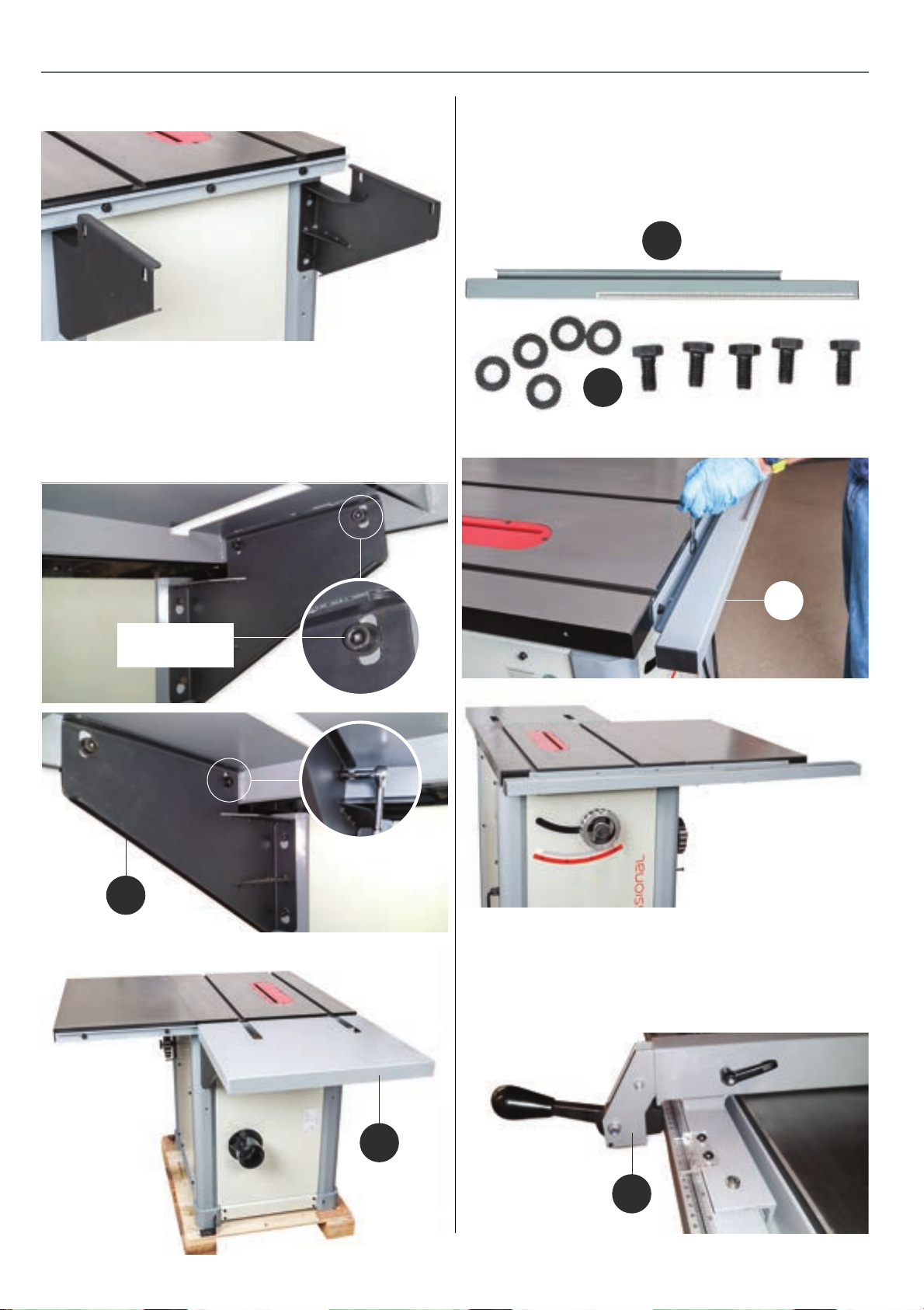
4. Place the rear extension table ( F ) down onto the
support brackets ( G ), lineup the threaded holes in the
extension table with the elongated slots in the angle
support brackets. Secure in place with the four short
caphead bolts and washers, see fig 22-23-24.
Fig 22-23-24
Fitting the Front Fence Rail & Fence Assembly
1. Locate the front fence rail ( B ) and five short bolts and
flat washers ( S ), see fig 25. Lineup the pre-drilled holes in
the fence rail with the ones to the front of the saws cast
iron table and secure using the five bolts and washers ( S )
see fig 26-27.
Fig 25
B
S
Fig 26-27
Caphead
bolt & washer
G
B
2. Find the rip fence assembly ( A ), lower the unit down
over the front fence rail ( B ). Push down locking
handle to lock the rip fence in place, see fig 28-29.
Fig 28
F
A
8
Page 9
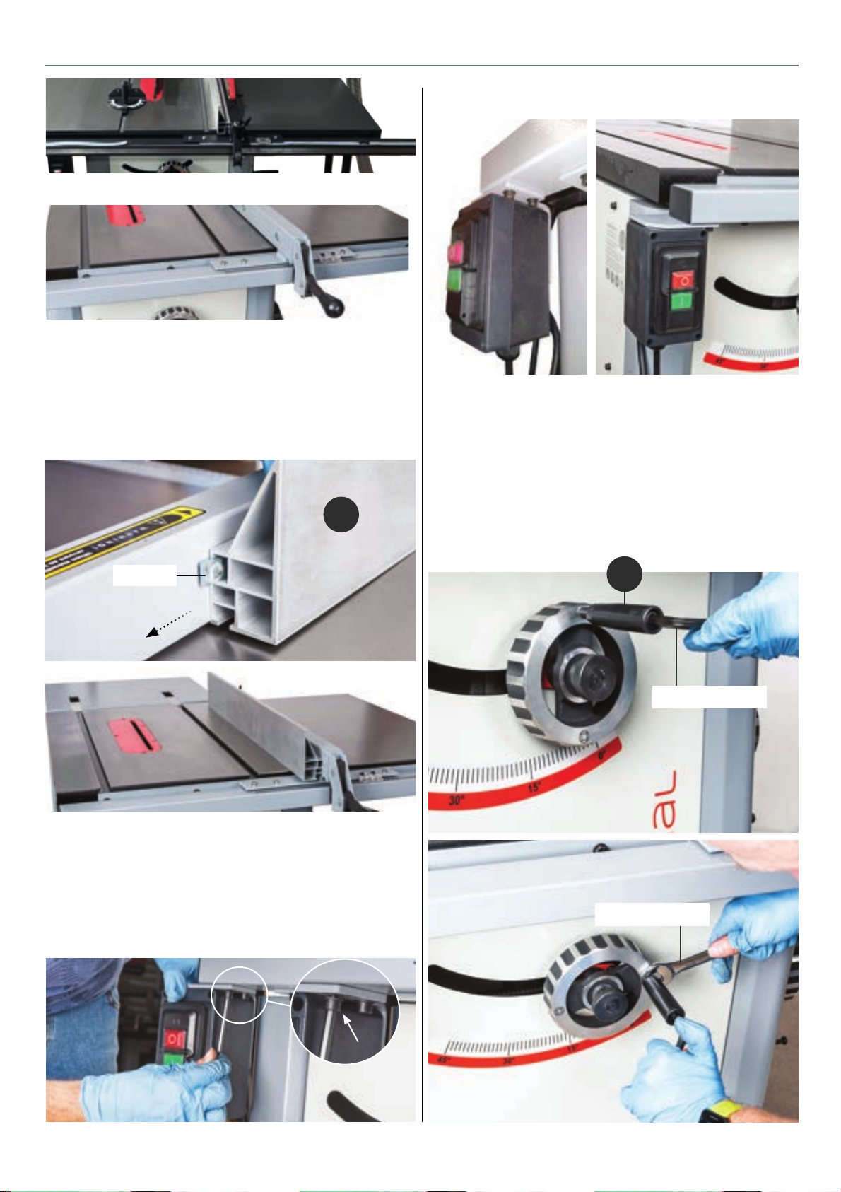
Fig 29
3. Locate the Aluminum sub fence ( D ). Position the sub
fence against the rip fence assembly ( A ), lineup the ‘T’
slots in the fence ( D ) with the ‘T’ bolts in the rip fence
and slide the sub fence on. Nip-up the three lift & shift
handles on the rip fence ( A ) to secure the fence ( D ) in
place, see 30-31.
Fig 30-31
D
ASSEMBLY
Fig 33 Fig 34
Fitting the Operating Handwheel Knobs
Find the two handwheel knobs ( O ), 16mm spanner and
8mm Hex key ( R ). Lightly screw the handwheel knobs
into the threaded hole in the operating wheels. Insert the
Hex key into the caphead recess to the end of the knobs
and while holding them in place nip-up the nuts with the
spanner to secure in place, see 35-36.
‘T’ Bolt
Mounting the Control Switch Box
Lineup the two holes in the contol switch mounting
bracket with the ones to the underside of the front
fence rail ( B ), secure in position with the two small
caphead scrrews and washers, see fig 32-33-34.
Fig 32
Fig 35-36
O
8mm Hex key
16mm Spanner
9
Continues over...
Page 10
ASSEMBLY
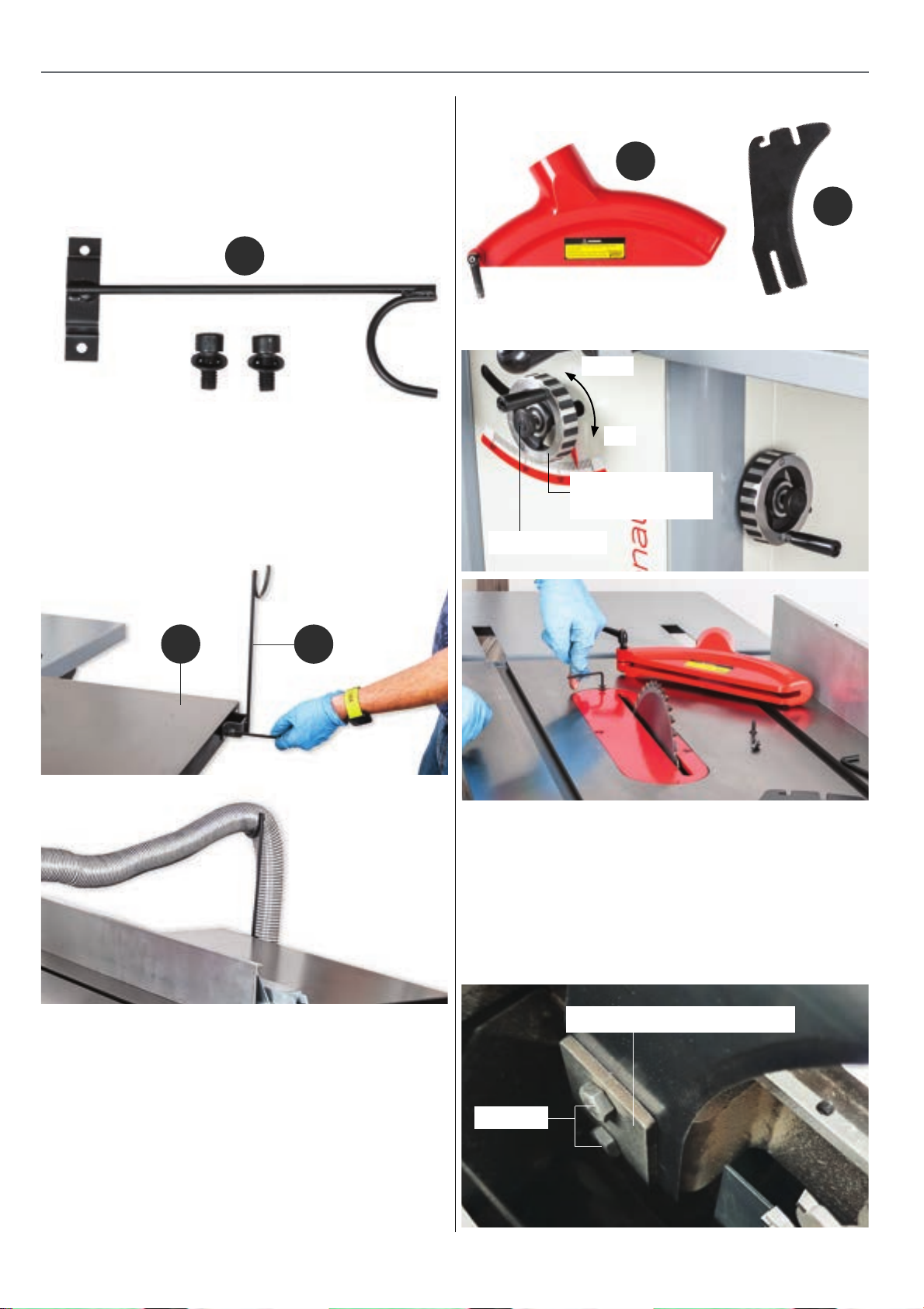
Fitting Flexible Hose Support Bracket
1. Locate the flexible hose support bracket and two small
caphead screws / washers ( L ), see fig 37.
Fig 37
L
2. LIneup the holes in support bracket ( L ) with the two
threaded holes to the side of the right hand extension
table ( E ) and secure in place with the caphead screws /
washers, see fig 38-39.
Fig 38-39
Fig 40
J
K
Fig 41-42
Down
Up
Rise & Full
operating wheel
Locking knob
E
Fitting the Riving Knife & Crown Guard
1. Locate the crown guard asssembly ( J )and the riving
knife ( K ), see fig 40.
L
4. Loosen the two bolts that hold the riving knife
clamping plate, see fig 43. Slide the riving knife ( K )
down between the plate and lightly tighten to hold the
riving knife in place, see fig 44-45. Check that the tip of
the knife has a clearance of 3-8mm between it and the
blade and tighten. Replace the insert plate and
countersink screws, see fig 46.
Fig 43
Riving knive clamping plate
2. Release the locking knob to the centre of the rise & full
operating wheel and raise the saw to its highest point by
turning the wheel clockwise, see fig 41.
3. Remove the table insert plate by removing the five
countersink screws, using the supplied 3mm Hex key.
Place it and the screws safely to one side, see fig 42.
Bolts
10
Page 11
ASSEMBLY
Fig 44-45
K
Fig 46 Fig 47
Locking
handle
Fig 49 Fig 50
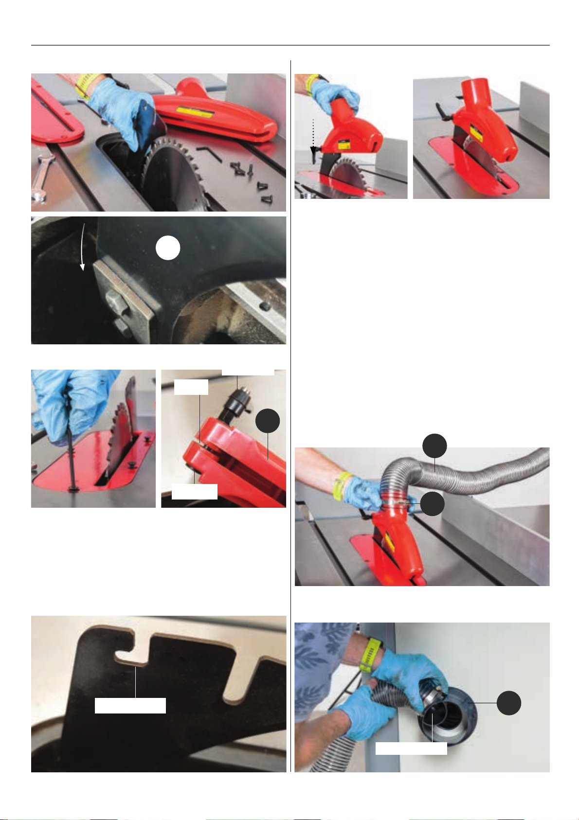
Fitting the Extraction Hose
1. Locate the long hose ( Q ) and the two remaining hose
clips ( M ).
2. Place a hose clip over one end of 63mm hose, slide
the hose over the extraction outlet on the crown guard
( J ). Secure in place by lightly tightening the hose clip.
Note: DO NOT OVERTIGHTEN, see fig 51.
3. Fit the other end of the hose to the 63mm outlet on
the 100mm spigot ( N ) to the rear of the machine as
shown in fig 52. Insert the hose over the support bracket
( L ).
Slot
J
Pin bolt
5. Loosen the Locking handle on the crown guard
( J ). ntroduce the slot to the rear of the crown guard, see
fig 47 down over the riving knife and insert the pin bolt
into the curved slot in the rear of the riving knife, see fig
48-49. Lightly tighten the handle to secure the guard in
place, see fig 50.
Fig 48
4. Replace both left & right side panels as explained on
page 05.
Fig 51
Q
M
Fig 52
Curved slot
N
63mm Outlet
11
Page 12
SET UP LEVELLING FINE TUNING
Always follow the step by step procedure in the
instruction manual. A poorly set up saw will not perform
to its full potential and may be dangerous to use.
Three crucial things when setting up any table saw
or panel saw-
• All extension tables are flat and level
with the main saw table
• All rip fences are in line with the blade
• Sliding tables are set slightly above (0.5mm max)
the level of the main saw table.
In the set up of most machinery including tables saws,
two tools that you will need to use are a 6” engineers
square and a minimum 36”/910mm straight edge, without
these toolbox essentials it is difficult to set the machine
up accurately.
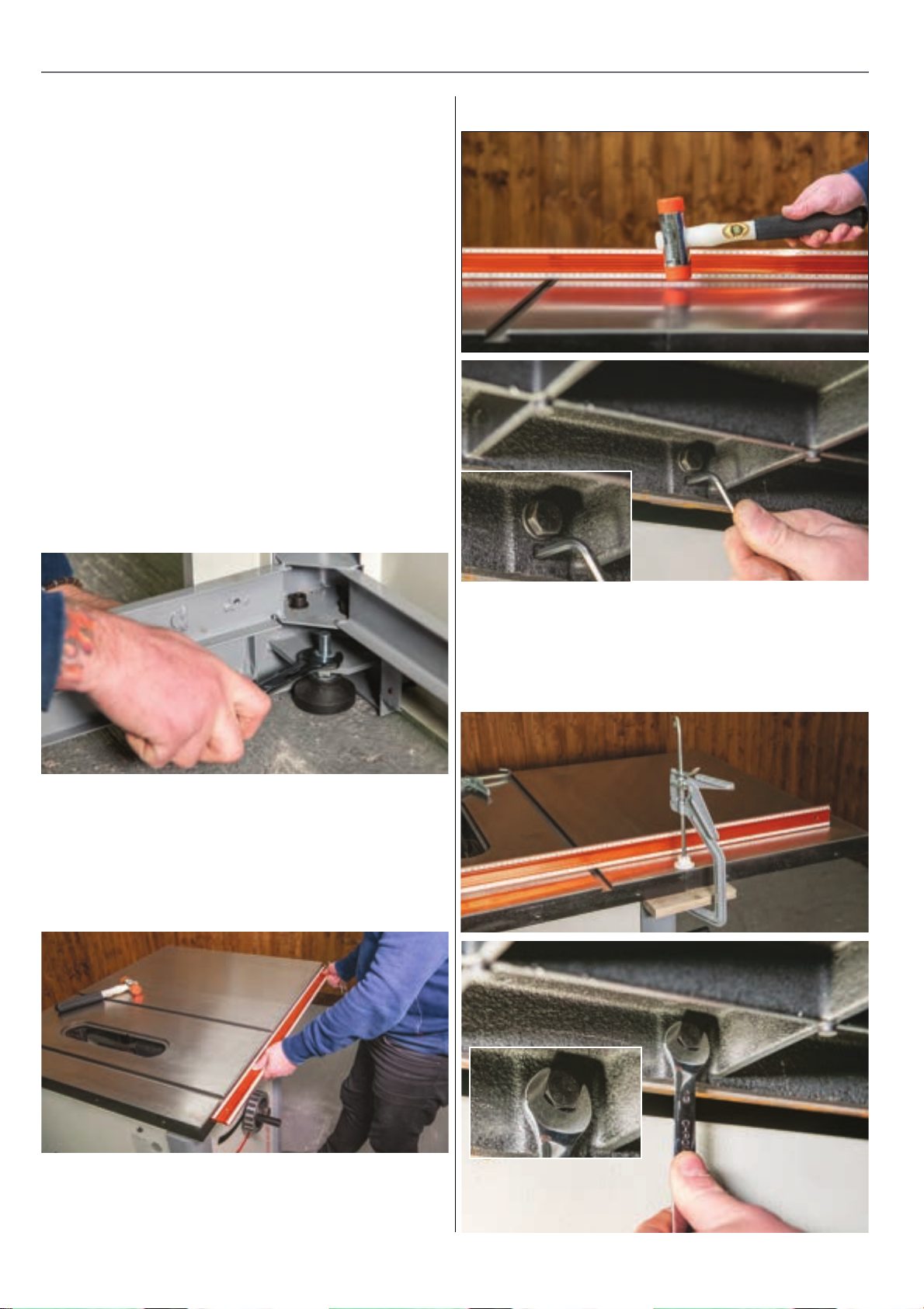
1. Firstly please ensure that the table saw is stable on the
floor & doesnt rock or wobble, adjustment can be made
via the feet located on the inside of the machine. You will
need to remove both side panels to do this, see fig 53.
Fig 53
Fig 55-56
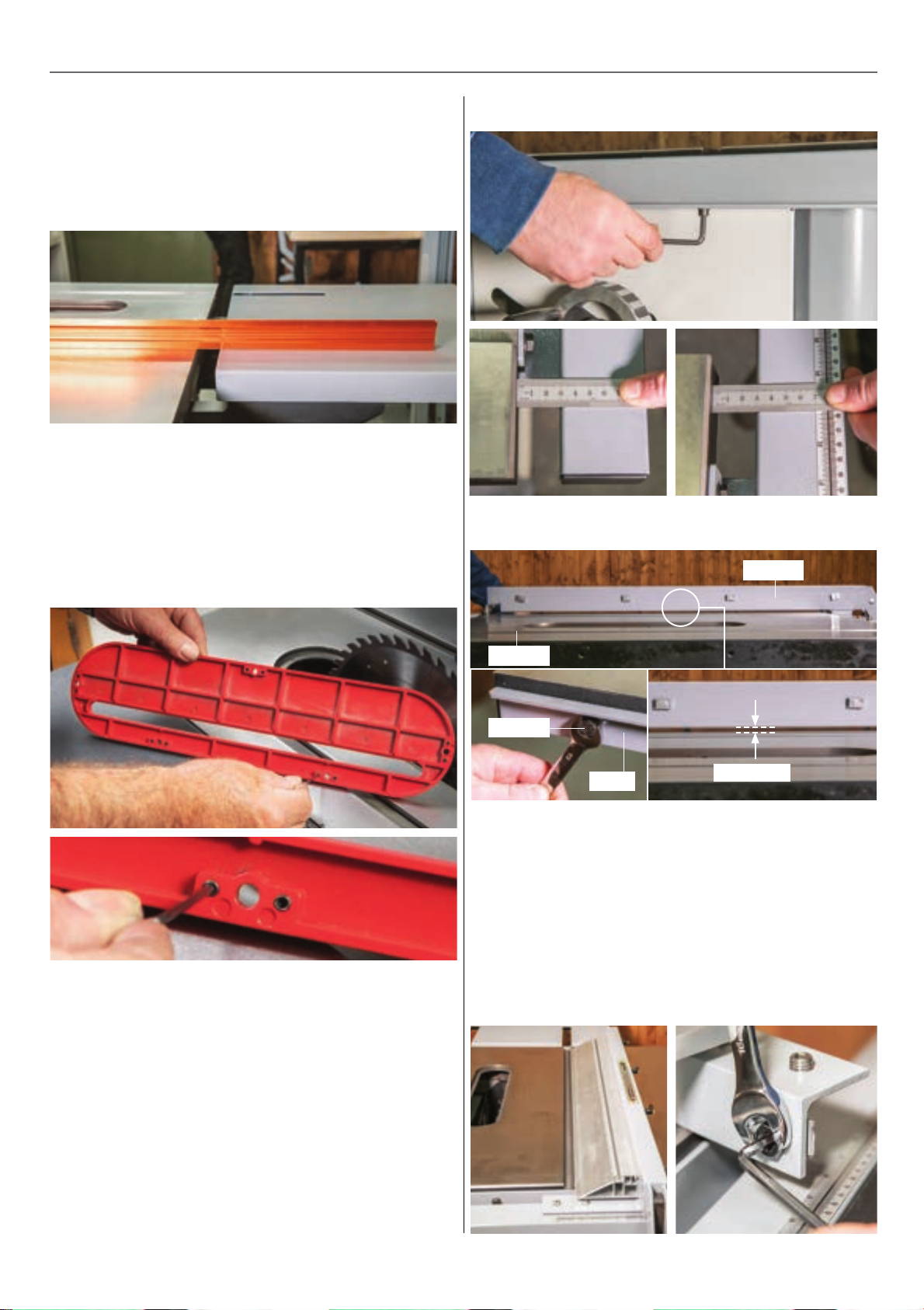
Right Hand Extension Table -
2. Once you have loosely bolted on the cast iron R/H
extension table , align the front face to the main saw
table,use a 36”/910mm straight edge or use the
aluminium sub fence supplied with the saw, see fig 54.
Fig 54
4. Move the straight edge to the front of the saw then
use a soft face clamp and a small piece of timber to align,
the grub screws to level then tighten in place, see fig 57.
Repeat the last process at the rear of the tables, see fig 58.
Fig 57-58
3. Place the straight edge in the middle of both tables
across the seam, use a soft face mallet to tap the
extension table up or down to align, then use the
grub screws to level. Then tighten the central 2 bolts,
see fig 55-56.
12
Page 13
SET UP LEVELLING FINE TUNING
Rear Extension Table -
5. Loosely Attached the rear extension table, then using
the straight edge move the table up or down to align the
main saw table, lock in place when aligned, see fig 59.
Fig 59
6. The table should be set at the same height as the
main saw table or very slightly lower (1mm max). This
table should not be set higher than the saw table as it
will prevent smooth feed through of timber.
7. Level the table insert to the main saw table by
adjusting the grub screws on the underside of the
table insert, see fig 60-61.
Fig 60-61
Fig 62-63-64
Fig 65
Fence
Fence Rails & Fence -
1. Ensure that the fence rail bracket is attached to the
front of the tables. Slightly undo the hex cap screws
underneath, measure the gap between the fence rail &
table edge to ensure that this is the same end to end,
see fig 62-63-64.
2. The mounting holes in the rear fence rail are slotted to
allow movement up or down. Ensure that the bolts are
loosened slightly then lift the rail up making sure that the
fence is around 3-4mm above the saw table, see fig 65.
Table
Bolt
Rail
3. The T style rip fence has complete adjustment to align
it to the saw blade / mitre fence slot & also to square it to
the table.
4. Firstly slide the fence over to the mitre fence slot, align
it then lock it off, see fig 66. If the fence seems out
of line then simply adjust the left hand or right hand grub
screws to align. You can also use these grub screws to
take out any movement (wobble) in the fence, see fig 67.
3-4mm
Fig 66-67
13
Continues over...
Page 14

SET UP LEVELLING FINE TUNING
5. To square the fence to the table firstly slide the sub
fence on at its high fence position, move it over towards
the blade then with the fence locked check for square,
see fig 68.
6. Adjustments are made by moving the grub screws on
the top of the fence up or down, see fig 69.
7. Finally with the sub fence still in the high position slide
the fence over until it makes very light contact with the
blade. Then undo the 2 pozi screws to move the scale to
read at zero, see fig 70.
Fig 68
Fig 71
Aligning / Adjusting the Riving Knife -
1. It is important to ensure that the riving knife ( K ) is
positioned correctly. The riving knife should be inline with
the blade & between 3 - 8mm away from the edge of the
blade, see fig 73-74.
2. To adjust the riving knife slightly undo the 2 bolts, this
will allow up & down movement to gain the 3 - 8mm
distance from the blade and will also allow for alignment
adjusting via the four grub screws, see fig 75.
Fig 72
Stop collar
Fig 69
Fig 70
Fig 73
Fig 74
3-8mm Clearance
Riving knife inline
with the blade
Blade
Squaring the Blade to the Table -
1. With the blade raised up to its highest point and not
tilted, offer a square up to the right hand side of the blade
plate avoiding the tips, see fig 71.
2. If the blade seems out of square a simple adjustment
can be made by moving the stop collar located inside the
machine on the threaded bar, see fig 72.
Fig 75
14
K
Grub screws
Bolts
Page 15
GENERAL USE OPERATION
ALWAYS REMEMBER TO DISCONNECT
THE POWER TO THE TABLE SAW WHEN
MAKING REPAIRS OR ADJUSTING BLADES
AND GUARDS.
ALWAYS REMEMBER TO READ THROUGH
THE MACHINE INSTRUCTIONS SUPPLIED.
1. Before you begin to use your Table saw, you will need
to establish that the machine and the blade you are
intending to use are suitable for the material you are
going to be cutting.
2. Check the sharpness of the blade. Is it too fine or too
coarse?
3. Does the machine have enough capacity to cope
with the size of material you are cutting?
4. Always ensure that the blade guard & riving knife
are fitted.
See Blade Selection Info on page…. 20
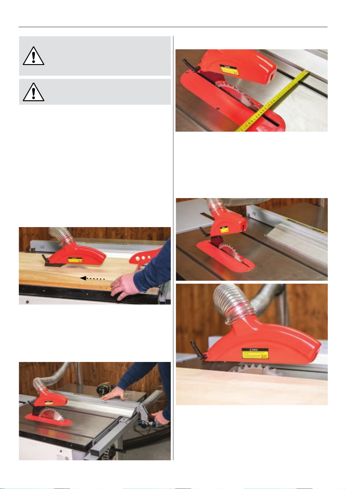
Fig 77
2. Slide the sub fence forward so the end of the sub fence
is just beyond the mid way point of the blade, see fig
78.
3. Adjust the blade height to match the timber thickness
- top of the blade around 20 - 25mm above the timber,
see fig 79.
Fig 78-79
Rip Cuts - Cutting Down the Grain
1. Position the rip fence to the right of the saw blade and
set the rip fence for desired width of cut using the scale
on the front rail, or measure the distance between the
R/H side of the blade teeth and the fence, see fig 76-77.
Fig 76
4. Standing to one side of the machine press the green
button & allow the machine to run up to full speed, see
fig 80.
5. Use the left hand to hold the timber against the
fence. Use the right hand to push the material down &
through the saw, see fig 81.
15
Continues over...
Page 16
GENERAL USE OPERATION
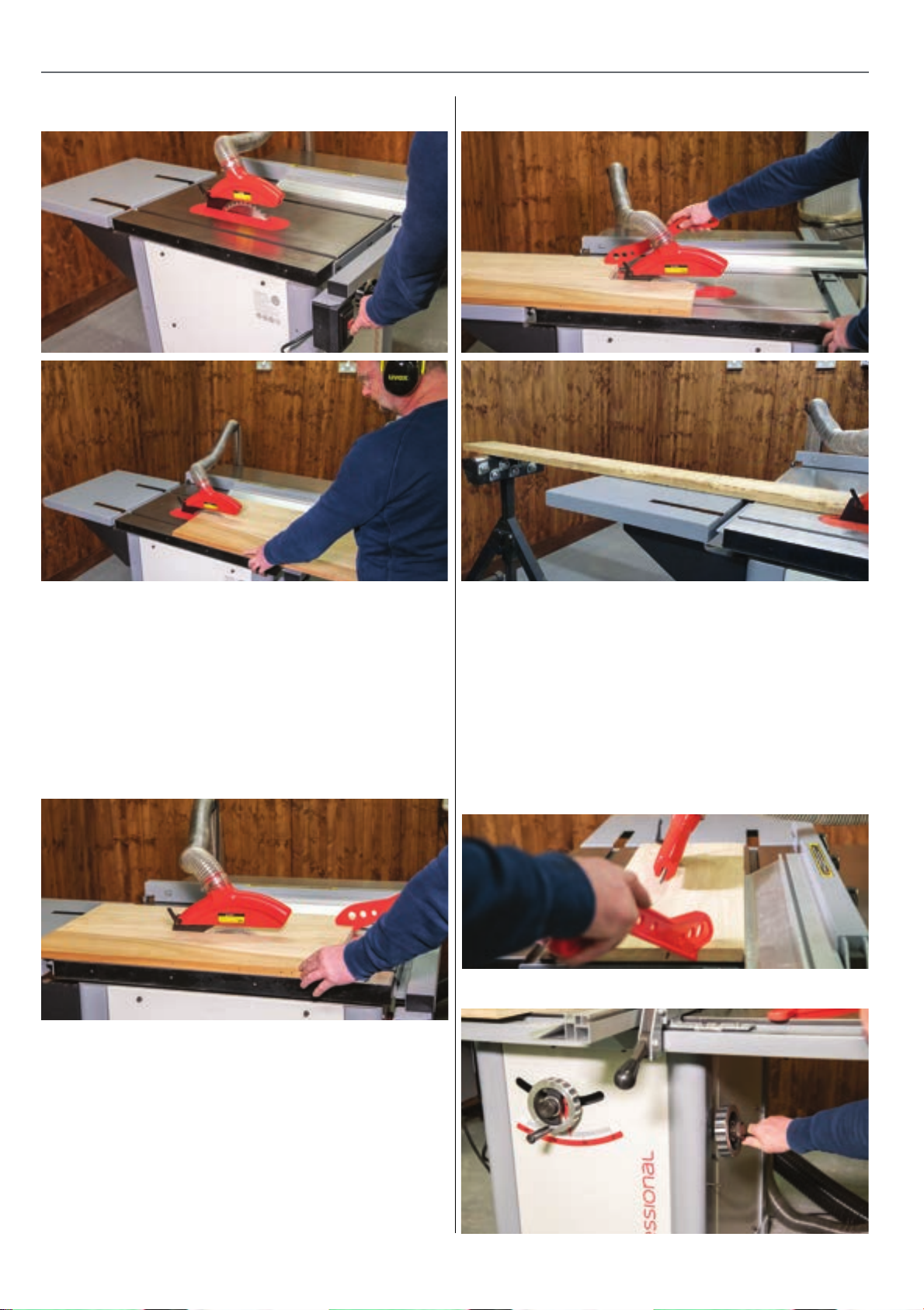
Fig 80-81
Fig 83-84
6. Use a push stick for all cuts that will bring your hands
within 250mm of the blade.
7. Position the right hand so it is NOT in direct line with
the saw blade. Remove the hand holding the stock
down as it approaches the saw blade and use a push
stick to guide the last 300mm of cut through the blade,
see fig 82.
Fig 82
8. Always push the workpiece completely past the blade
at the end of a cut to reduce the possibility of kickback,
see fig 83.
Bevel Cuts -
1. Make sure the timber is planed flat, square, and with
parallel edges. Any warp, deviation from square, or an
angled edge, can lead to blade burn or to the timber
being lifted from the table and risking kickback.
2. Using the tilt handle on the side of the machine set the
over to the required angle, the riving knife & blade guard
will tilt with the blade, set the blade height to clear the
timber by around 20-25mm, see fig 85.
Fig 85
9. When ripping long boards use a support roller before
& after the cut to support the workpiece as it comes
through the saw, see fig 84.
16
Page 17
GENERAL USE OPERATION
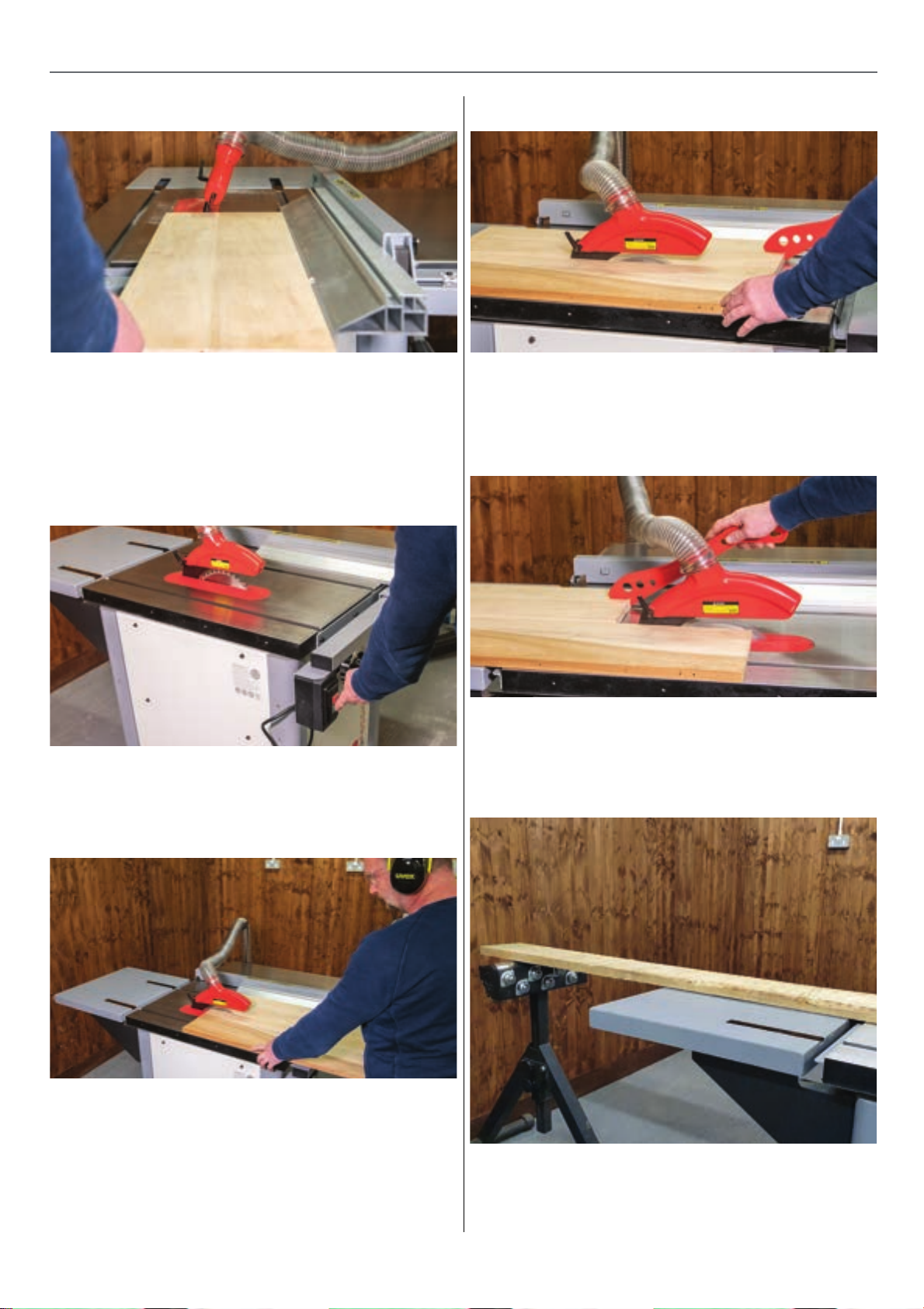
Fig 86
3. Position the sub fence to the lower position & the rip
fence to the desired cut width, see fig 86.
4. Standing to one side of the machine press the green
button & allow the machine to run up to full speed,
see fig 87.
Fig 87
Fig 89
9. Always push the workpiece completely past the blade
at the end of a cut to reduce the possibility of kickback,
see fig 90.
Fig 90
6. Use the left hand to hold the timber against the fence.
Use the right hand to push the material down & through
the saw, see fig 88.
Fig 88
7. Use a push stick for all cuts that will bring your hands
within 250mm of the blade.
8. Position the right hand so it is NOT in direct line with
the saw blade. Remove the hand holding the stock down
as it approaches the saw blade and use a push stick to
guide the last 300mm of cut through the blade, see fig
89.
10. When ripping long boards use a support roller
before & after the cut to support the workpiece as it
comes through the saw, see fig 91.
Fig 91
11. When the right hand side off cut is small a second
push stick should be used to push the offcut through &
past the blade.
17
Continues over...
Page 18
GENERAL USE OPERATION
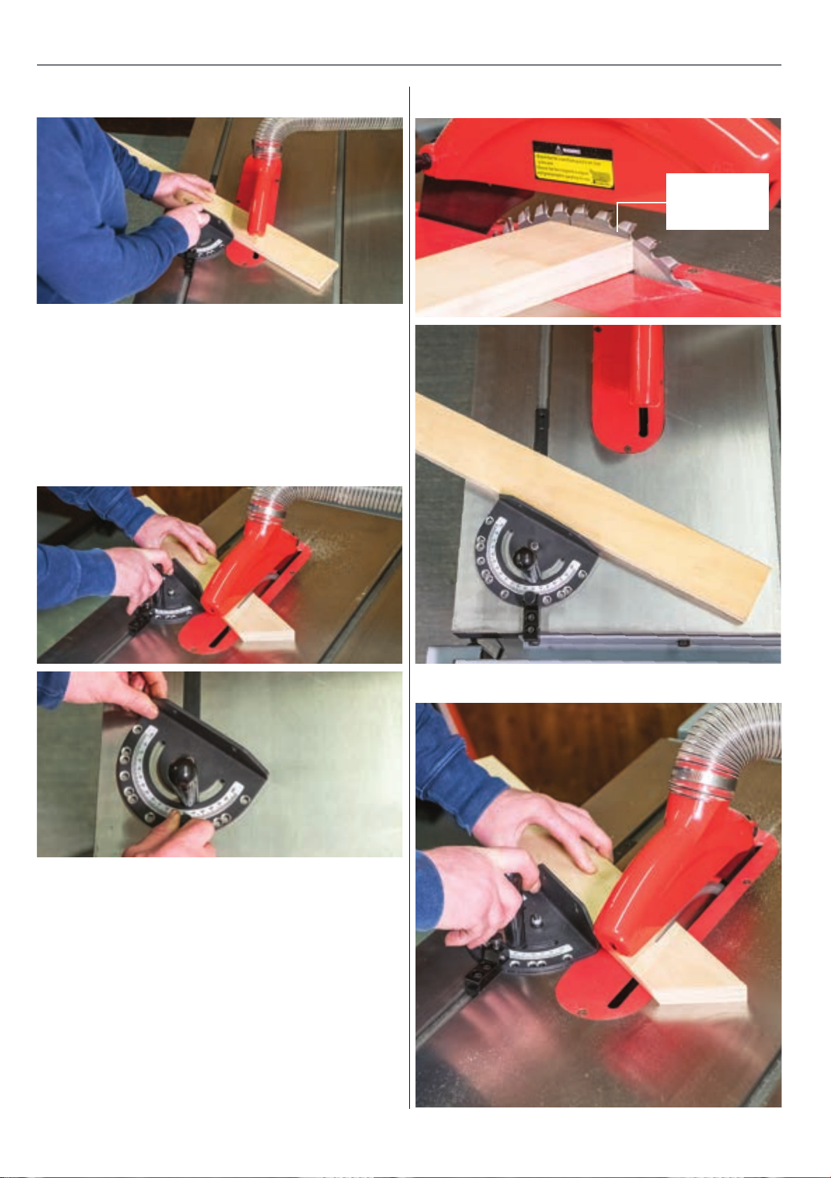
Cross cuts - Cutting Across the Grain
Crosscuts are usually made with a medium to fine tooth
blade.
See Blade Selection Info on page…. 20
1. Make sure the saw guard and riving knife are in place
when crosscutting.
2. Always use the mitre gauge or sliding table when
crosscutting, do not make crosscuts free hand!, see fig 92.
Fig 92-93
Fig 94-95
20-25mm
above the
timber
3. Most workers prefer to use the left table slot for the
mitre gauge when crosscutting, see fig 93.
4. Adjust the blade height to match the timber thickness
- top of the blade around 20 - 25mm above the timber,
see fig 94.
5. Select the desired cutting angle & ensure that all is
locked in place, see fig 95.
6 Hold the workpiece against the mitre fence with the
left hand and use the right hand to advance the mitre
gauge and material through the cut, see fig 96.
Fig 96
7. Provide support for any material which extends
beyond the edge(s) of the saw table.
18
Page 19
TROUBLESHOOTING
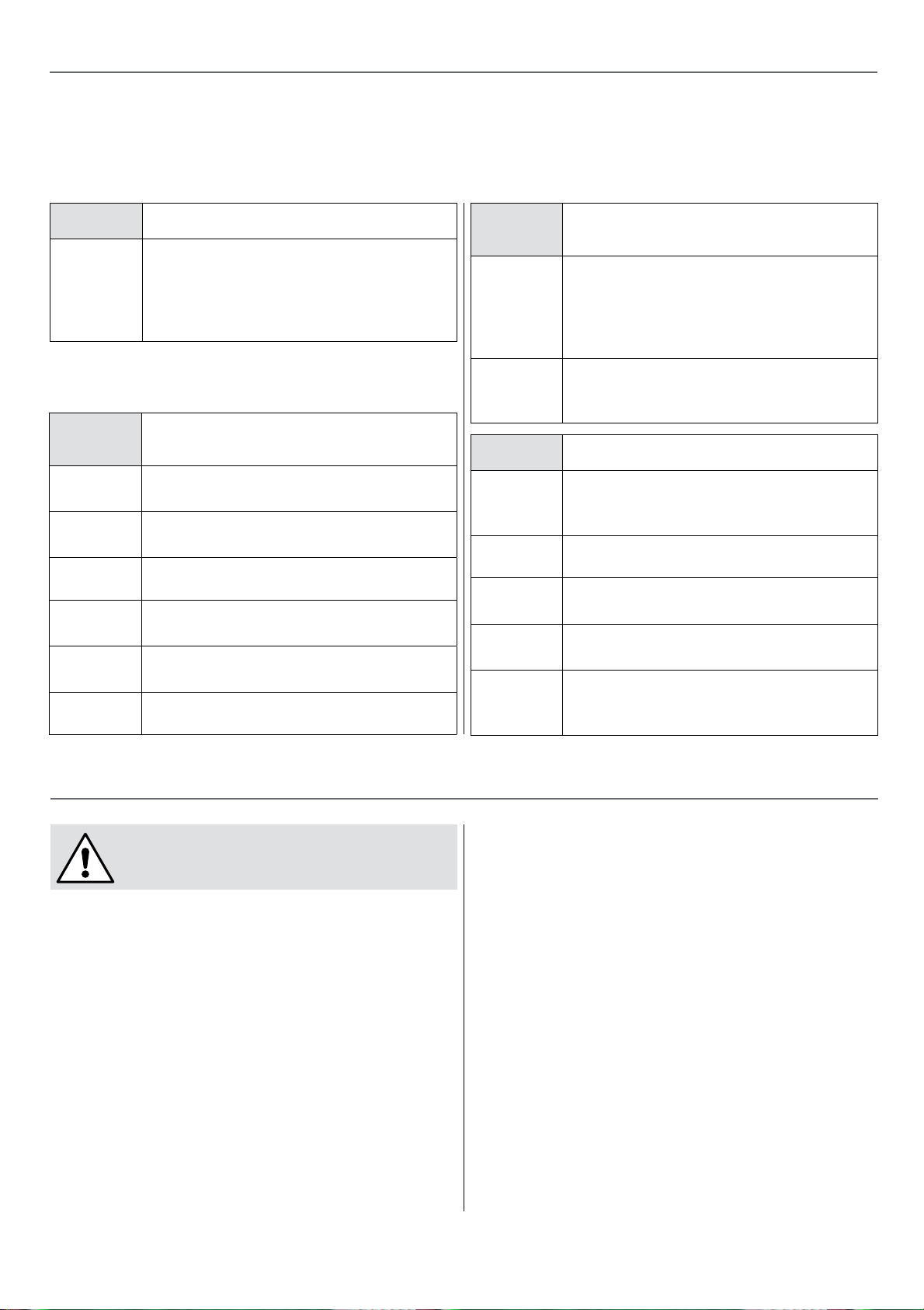
Table saws & panel saws are relatively simple machines, with all machinery regular cleaning, servicing & the use of
extraction (all preventative maintenance) are essential to get the best from your saw.
‘My table saw won’t cut straight”
•
Check that your fence is in line with the
blade, also check that the blade is square
to the table. Information on how to correct
this will be found in this instruction
manual.
•
•
“My saw slows down
when cutting”
•
•
Blade may be blunt or too fine for the
thickness of material.
Overfeeding, slow down the feed through
the blade.
•
•
•
Drive belt may be loose or worn.
•
•
Check that your fence is in line with the
blade.
•
•
Ensure that the saw is not running on a
long extension lead.
•
•
Motor capacitor may be faulty.
“Why am I getting a lot of
splintering along the cut edge”
The blade is probably blunt or too coarse,
if a smoother cleaner cut is required then
change the blade for one with more teeth.
Lowering the blade height to about 25mm
above the timber can also help.
Slow your feed speed down & check that
the fence is in line with the blade as back
cutting can occur.
“Excessive vibration ”
The blade may be damaged, check the
blade , replace if any missing teeth or burn
marks are seen.
Check that the blade is fitted correctly.
Check fence to blade alignment, adjust as
necessary.
The saw is not positioned on a flat stable
floor surface.
The timber may not stable and sat flat
on the table, you may be getting board
bounce, choose a flatter surface.
DISCONNECT THE MACHINE FROM
THE MAINS SUPPLY.
Preventative maintenance is crucial if you want your
machine to perform to its full potential. I.E. Use good
quality resin free sharp blades; this will greatly cut down
the load put on to motors, drive belts and gears.
Use adequate extraction, this will help keep the machines
internal mechanisms clean and also help keep your work
area clear from dust and shavings.
Periodically or after quite heavy use it is recommended
that the following maintenance be made to the table saw.
MAINTENANCE
• Check blades for ware or damage
• Clean inside the machine, slides, threads,
gears and remove all off cuts & debris.
• Lubricate slides, threads, gears
• Check drive belt for ware or damage
• Clean guards & check for damage
• Check alignment of fences & guides
• Clean & wax cast iron tables
19
Continues over...
Page 20
MAINTENANCE
Blade Selection/Info -
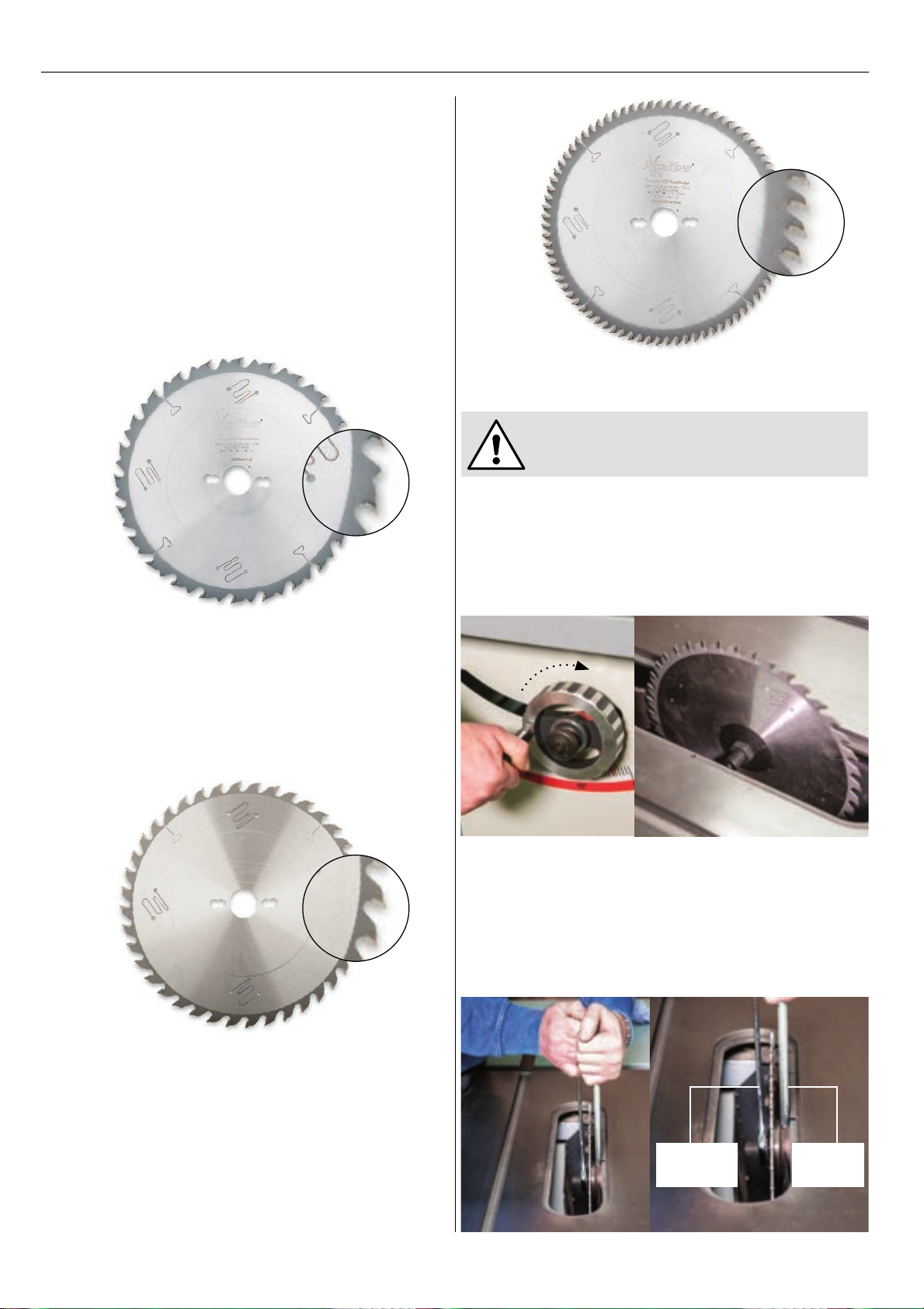
ALWAYS ensure that you are using the correct blade
dimensions, the blade diameter, the bore size & the
kerf (cutting width) match the blade that is supplied
with the table saw from new.
Coarse Blade -
Low tooth count, around 20 - 30 teeth, ideal for table saws
to do ripping cuts down the grain where a smooth finish
is not so important, see fig 97.
Fig 97
Fig 99
Blade Change -
DISCONNECT THE MACHINE FROM
THE MAINS SUPPLY.
Removing Blade
1. Undo the six screws and remove the table insert, then
wind the blade up to its highest point, see fig 100.
General Purpose Blade -
Medium tooth count, around 40 - 50 teeth, where a user
may cut a wide range of timber both natural & man made
board & doesn’t want to change blades too often, see fig
98.
Fig 98
Fig 100
2. Insert the tommy bar into the hole on the inner spindle
collar then use the 22mm spanner to undo the blade nut
THIS IS A LEFT HAND THREAD, THE NUT WILL TURN
THE SAME DIRECTION AS THE BLADE ROTATION, see fig
101-102.
Fig 101
Fine Tooth Blade
High tooth count, around 60 - 100 teeth suited to cutting
finer delicate thinner timbers where a smooth finish &
limited breakout is required. Also the ideal blade for
cutting faced man made boards, see fig 99. NOTE: NOT
RECOMMENDED FOR RIP CUTS!
20
22mm
Spanner
Tommy
bar
Page 21
MAINTENANCE
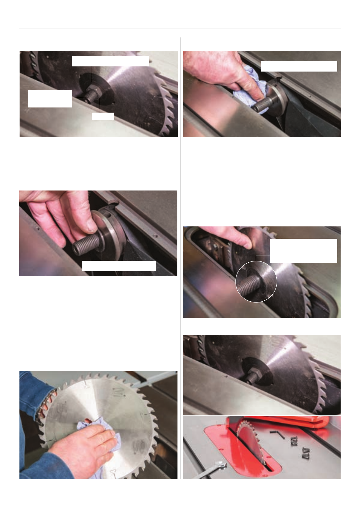
Fig 102
Outer clamping flange
Left handed
thread
Nut
3. Remove the nut, the outer clamping flange and the
blade. Take care not to lose the blade locating bush, also
take care not to damage the blade during removal, see fig
103.
Fig 103
Fig 105
Inner clamping flange
3. Refit the outer clamping flange & retighten the blade
clamping nut. Replace the table insert, see fig 107.
4. Before powering up the machine rotate the blade by
hand to ensure all is running true, also ensure that the
blade guard is repositioned.
5. The riving knife will not need adjusting providing the
same, correct blade has been fitted.
Blade locating bush
Refitting the Blade -
1. Before fitting the blade ensure that the inner & outer
clamping flanges & blade plate are clean & free from
wood dust, see fig 104-105.
2. Slide the blade centering bush onto the spindle, then
slide the blade onto the spindle ensuring that the blade
is positioned over the blade locating bush, see fig 106.
Fig 104
Fig 106
NOTE: Ensure the
blade is seated over
the locating bush
Fig 107
21
Page 22
OPTIONAL ACCESSORIES
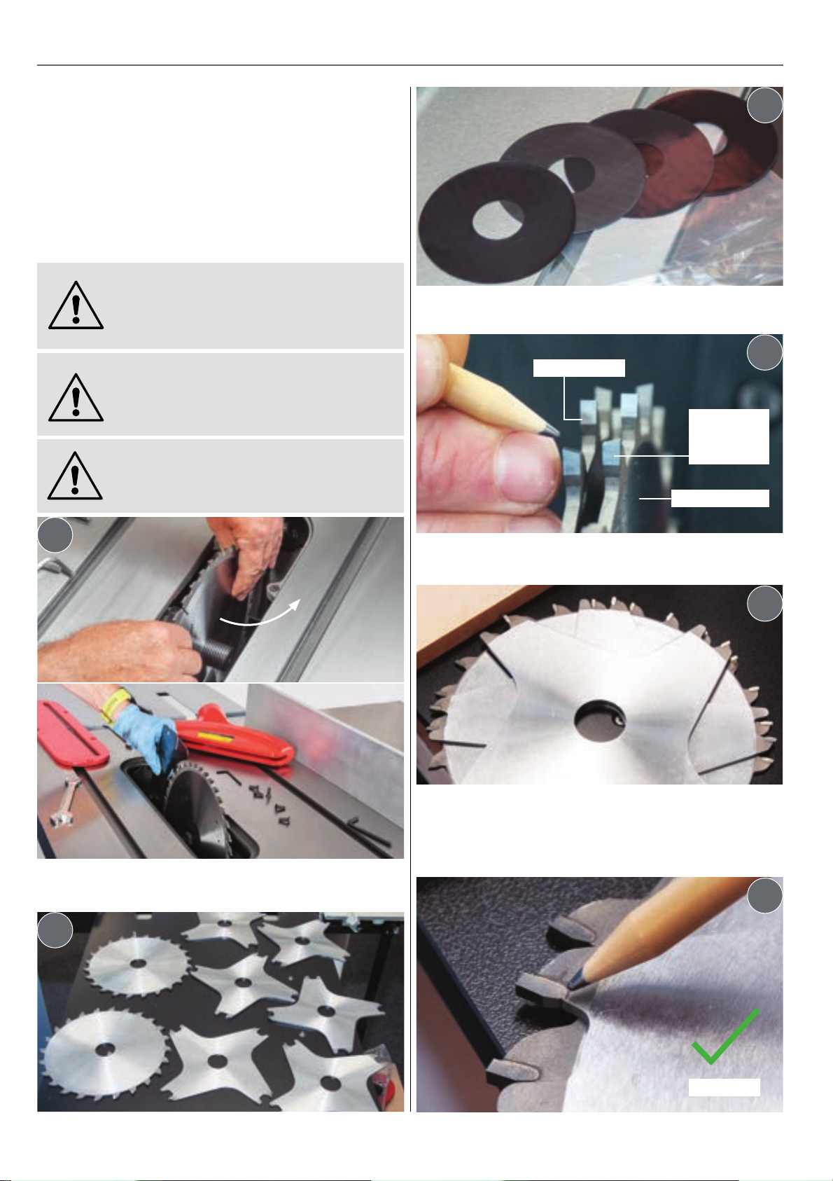
Dado Blade Set
This 204mm diameter Dado Blade Set comprises 2 x 24
tooth TCT outer blades, 6 inner chipper blades and 4
spacers. The chippers and spacers fit between the outer
TCT blades. Simply select the inner chippers and spacers required to cut the width of slot required. The outer
blades are 3.2mm. The inner chippers are 4 x 3.0mm, 1 x
2.2mm and 1 x 1.5mm. The spacers are 2 x 0.4mm and 2 x
0.3mm.
NOTE: THE DADO HEAD SHOULD NEVER
BE USED TO CUT THROUGH THE TIMBER,
IT IS FOR MACHINING GROOVES USING
LIGHT, MULTIPLE CUTS!
THE DADO BLADE CAN CUT GROOVES
UP TO A MAXIMUM 18MM IN WIDTH
DEPENDING ON CAPACITY OF THE
MACHINE BEING USED!
DISCONNECT THE MACHINE FROM THE
MAINS SUPPLY BEFORE CONTINUING!
3
Layout the TCT outer blades, chipper blades & the spacers.
4
Inner blade
Tooth
pointing
inward
Outer blade
1
Remove the standard blade and riving knife and place
safely away.
2
Make sure the teeth of the inner and outer blades are
facing inward.
5
Find a scrap piece of timber the thickness of the cut as a
guide. Place the inner blade against the timber and start
stacking the chipper blades on top. Make sure the teeth
are spaced equally and pointing foward.
6
22
Correct!
Page 23
OPTIONAL ACCESSORIES
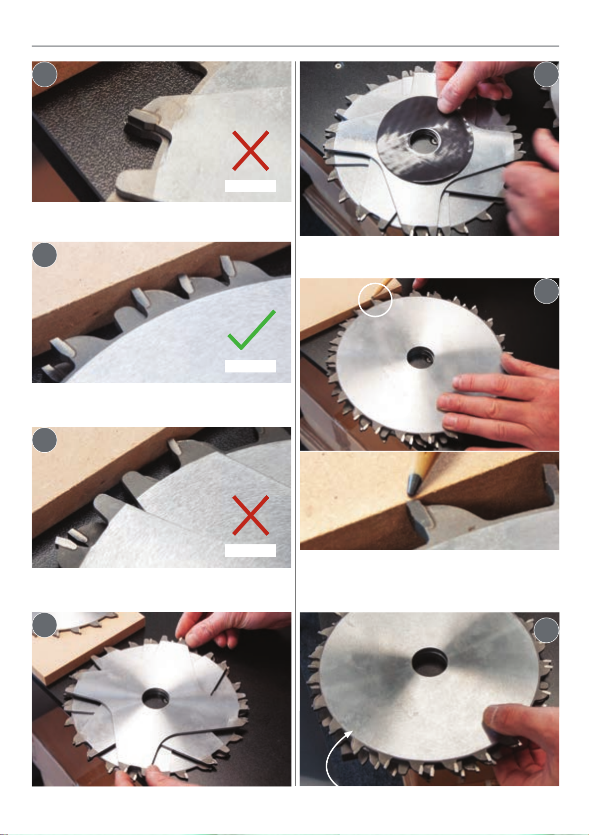
7
DO NOT OVERLAP the blade teeth.
8
11
Wrong!
Use the supplied spacers between the blades to make
small adjustments in the height.
12
Outer TCT blade
Correct!
The teeth equally spaced and pointing forward.
9
Wrong!
The teeth not equally spaced and not pointing forward.
10
Place the outer TCT blade on top and check the tooth is
the same depth as the timber. If the blade is too high/low,
rearrange the chipper blades and spacers until the correct
depth is reached.
13
Chipper blade
Outer TCT blade
23
Page 24
OPTIONAL ACCESSORIES
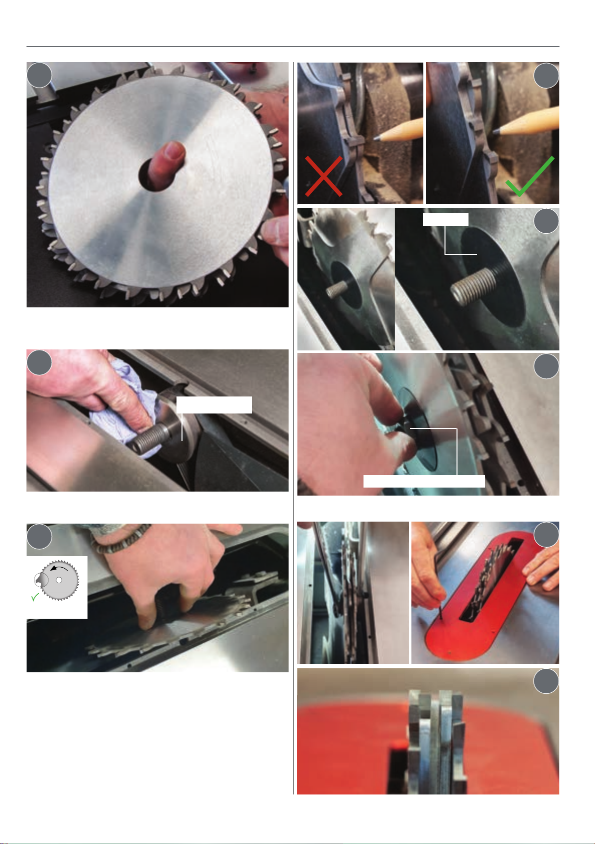
14
Inner TCT blade
Turn the ‘Dado’ blade assembly over so the inner TCT
blade is on top in preparation for installation.
15
Spacer
17
18
19
Plate flange
Clean the inner and outer plate flanges
16
Teeth forward
Slide the inner TCT blade over the shaft and up against
the inner plate flange. Make sure the teeth are pointing
forward. Mount each blade and spacers in turn onto the
shaft.
Outer plate flange/nut
Make sure the plate ange slots over the nut’s recess.
20
21
Important note: make sure to space the blade teeth
equally as shown in fig 17. Once all the blades are on,
replace the outer flange/nut and resecure. Replace the
insert plate.
24
Page 25
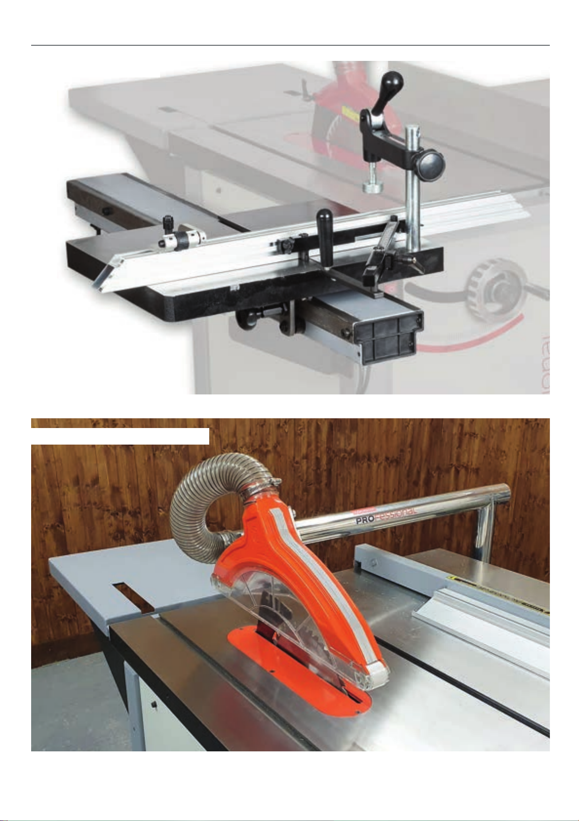
Sliding Table Accessory
OPTIONAL ACCESSORIES
Overhead Crown Guard Accessory
25
Page 26
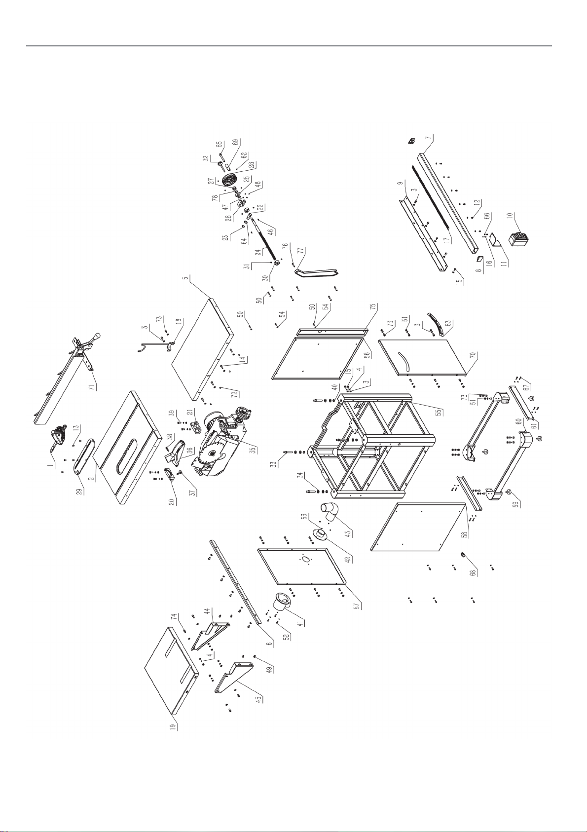
AP254SB EXPLODED DIAGRAMPARTS LISTS
Diagram/Parts List A
26
Page 27
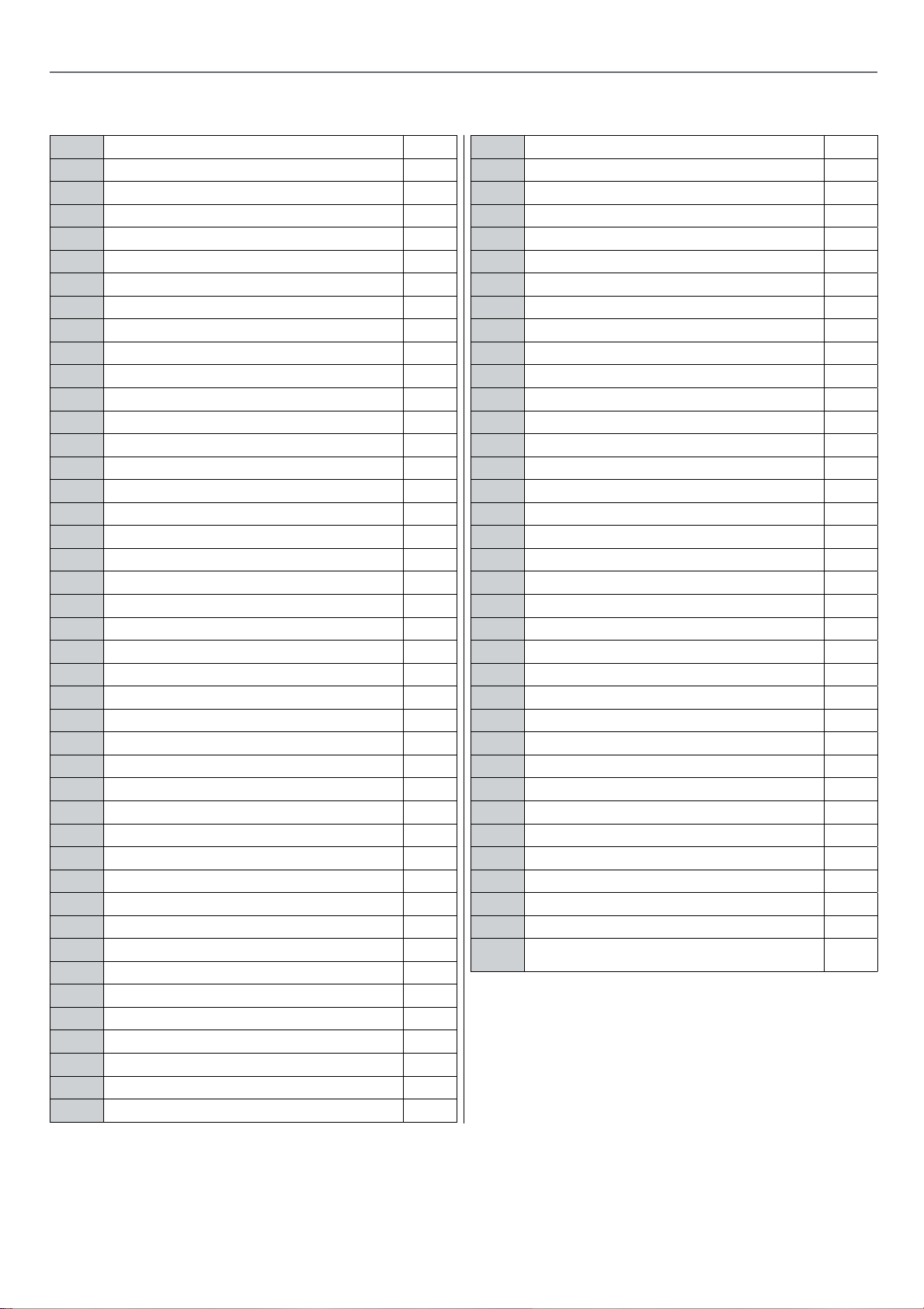
AP254SB EXPLODED DIAGRAMPARTS LISTS
No. Descriptionw QTY
1 Mitre Gauge Assembly 1
2 Main Worktable 1
3 Washer 8Mm 50
4 Spring Washer 8Mm 10
5 Extension Table 1
6 Rear Fence Rail 1
7 Front Fence Rail 1
8 End Cap,Front Fence Rail 2
9 Support Bracket,Fence Rail 1
10 Main Switch 1
11 Mounting Bracket,Switch 1
12 Hex.Socket Cap Head Screw M6X10 6
13 Hex.Socket Countersunk Head M5X15 5
14 Hex.Socket Cap Head Screw M8X25 4
15 Hex.Bolt M8X16 12
16 Hex.Socket Cap Head Screw M5X12 2
17 Scale 1
18 Dust Hose Support 1
19 Rear Extension Table 1
20 Rear Trunnion 1
21 Fron Trunnion 1
22 Tilt Leadscrew Nut 1
23 Circlips For Shaft 1
24 Tilt Leadscrew 1
25 Tilt Limit Block 1
26 Mounting Support 1
27 Stopping Hoop 1
28 Handwheel 1
29 Table Insert 1
30 Retainer Ring 2
31 Hex.Socket Set Screw M8X6 6
32 Locking Nail 1
33 Step Screw 4
34 Big Washer 12 8
35 Mechanism Assembly 1
36 Blade Guard 1
37 Ratchet Lever 1
38 Locking Bolt,Blade Guard 1
39 Hex.Bolt M8X25 4
40 Hex.Nut M12 4
41 Tie-In B 1
42 Tie-In A 1
43 Dust Collection Hose 1
44 Supporting Bracket A,Rear Extension Table 1
45 Supporting Bracket B,Rear Extension Table 1
46 Semi-Round Key 3X16 2
47 Big Washer 4 2
48 Cross Recessed Pan Head Screw M4X8 2
49 Hex.Socket Cap Head Screw M8X12 4
50 Hex.Socket Cap Head Screw M6X20 15
51 Hex.Nut M8 24
52 Cross Recessed Pan Head Screw M5X20 4
53 Hex.Nut M5 4
54 Washer 6 21
55 Column Frame,Machine Body 1
56 Right Panel,Machine Body 1
57 Rear Panel,Machine Body 1
58 Left Panel,Machine Body 1
59 Screw Rod 4
60 Leveling Foot 2
61 Connecting Board,Machine Body 2
62 Hex.Socket Set Screw M6X6 2
63 Angle Scale 1
64 Wave Washer 21 1
65 Hex.Socket Cap Head Screw M10X80(Half Screw) 1
66 Washer 5 14
67 Hex.Socket Cap Head Screw M5X25 8
68 Cable Gland M20 1
69 Knob 1
70 Front Panel,Machine Body 1
71 Rip Fence Assembly 1
72 Hex.Socket Set Screw M8X10 4
73 Hex.Socket Cap Head Screw M8X16 22
74 Hex.Socket Cap Head Screw M8X20 4
75 Right [Anel Section,Machine Body 1
76 Screw 1
77 Push Stick 1
78 Thrust Washer 30X17X0.8 2
27
Page 28
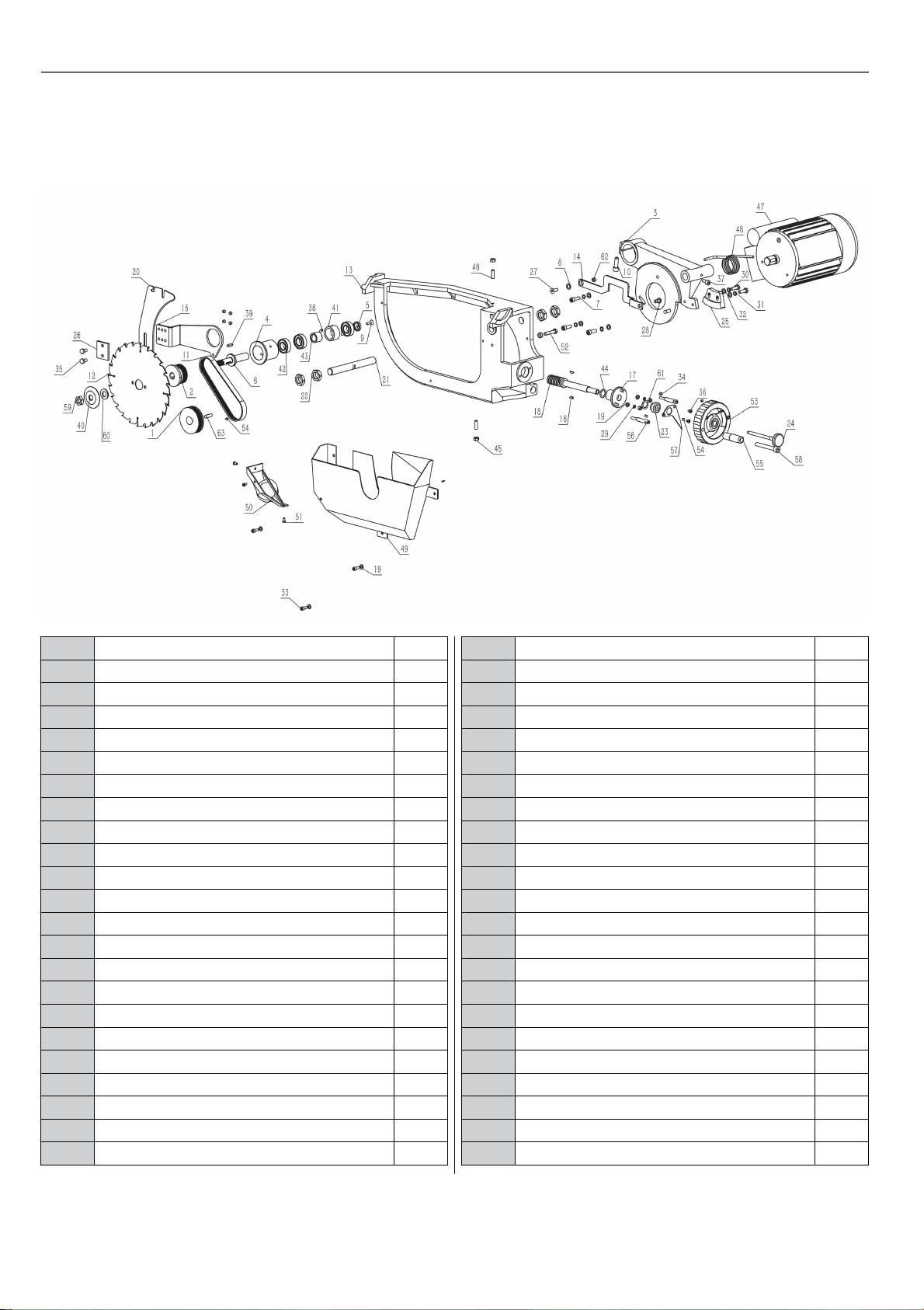
EXPLODED DIAGRAMPARTS LISTS
Diagram/Parts List B
No. Description QTY
1 Driving Pulley B 1
2 Shaft Pulley 1
3 Shaft Base 1
4 Arbor Shaft Sleeve 1
5 Arbor Shaft Ending Bushing 1
6 Blade Shaft 1
7 Hex.Socket Cap Head Screw M8X25 3
8 Washer 10 1
9 Hex.Socket Cap Head Screw M6X12(Left) 1
10 Hex.Socket Cap Head Screw M10X30 1
11 Driving Belt 1
12 Saw Blade 1
13 Mounting Base 1
14 Connection Rod Of Riving Knife Bracket 1
15 Riving Knife Bracket 1
16 Semi-Round Key 3X16 2
17 Connection Seat 1
18 Lifting Worm 1
19 Washer 6 5
20 Riving Knife 1
21 Shaft 1
22 Thin Nut M20X1.5 4
23 Stopping Hoop B 1
24 Locking Nail B 1
25 Lifting Worm Wheel 1
26 Press Board,Riving Knife 1
27 Hex.Socket Countersunk Head M8X20 1
28 Pulling Rod Shaft 1
29 Spring Washer 6 2
30 Hex.Bol M8X25 2
31 Spring Washer 8 5
32 Washer 8 5
33 Hex.Socket Cap Head Screw M6X12 3
34 Hex.Socket Set Screw M8X6 6
35 Hex.Bolt M8X16 2
36 Cross Recessed Pan Head Screw M5X8 2
37 Hex.Socket Cap Head Screw M8X16 1
38 Spring Pin 6X10 2
39 Key 5X20 1
40 Arbor Flange 1
41 Arbor Shaft Bushing A 1
42 6004 Bearing 3
43 Arbor Shaft Bushing B 1
44 Thrust Washer 30X17X0.8 2
45 Hex.Nut M8 3
28
Page 29
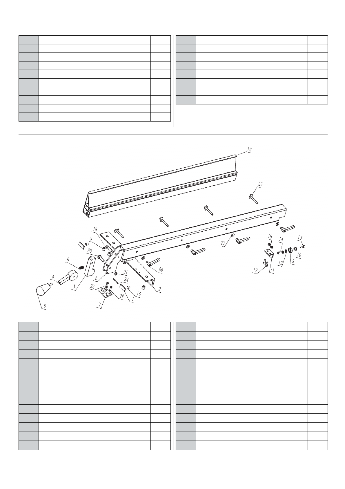
EXPLODED DIAGRAMPARTS LISTS
46 Hex.Socket Flat Head Set Screw M8X6 2
47 Motor 1
48 Torsion Spring 1
49 Dust Collection Cover 1
50 Dust Outlet,Dust Collection Cover 1
51 Cross Recessed Pan Head Screw M5X10 3
52 Hex.Bolt M8X40 1
53 Handwheel 1
54 Hex.Socket Set Screw M6X6 3
55 Handle 1
Diagram/Parts List C
56 Pointer Seat 2
57 Pointer B 1
58 Hex.Socket Cap Head Screw M10X80 1
59 Thin Nut M16X2 (Left) 1
60 Variable Diameter Sleeve 1
61 Hex.Nut M6 2
62 Hex.Self-Locking Nut M8 1
63 Key 8X25 1
No. Description
1 Pad
2 Sling Rail Carrier
3 Locking Block
4 Locking Cam
5 Nylon Screw
6 Fence Lock Knob
7 Pointer
8 Spring
9 Bearing 61900
10 Bearing Bushing
11 Bearing Support
12 Washer 6
13 Hex.Socket Countersunk Screw M6X22
QTY
2
1
1
1
3
1
1
1
1
1
1
2
1
14 Hex.Self-Locking M6
15 Hex.Socket Set Screw M10X10
16 Rip Fence
17 Hex.Socket Cap Head Screw M6X12
18 Hex.Nut M6
19 Semi-Round Step Bolt M6X35
20 Semi-Round Step Bolt M8X35
21 Hex.Self-Locking M8
22 Washer 5
23 Cross Recessed Pan Head Screw M5X10
24 Spring Pin 5X32
25 T-Bolt
26 Ratchet Lever
27 Big Washer 6
29
2
2
1
2
2
1
1
1
2
2
1
4
4
4
Continues over...
Page 30
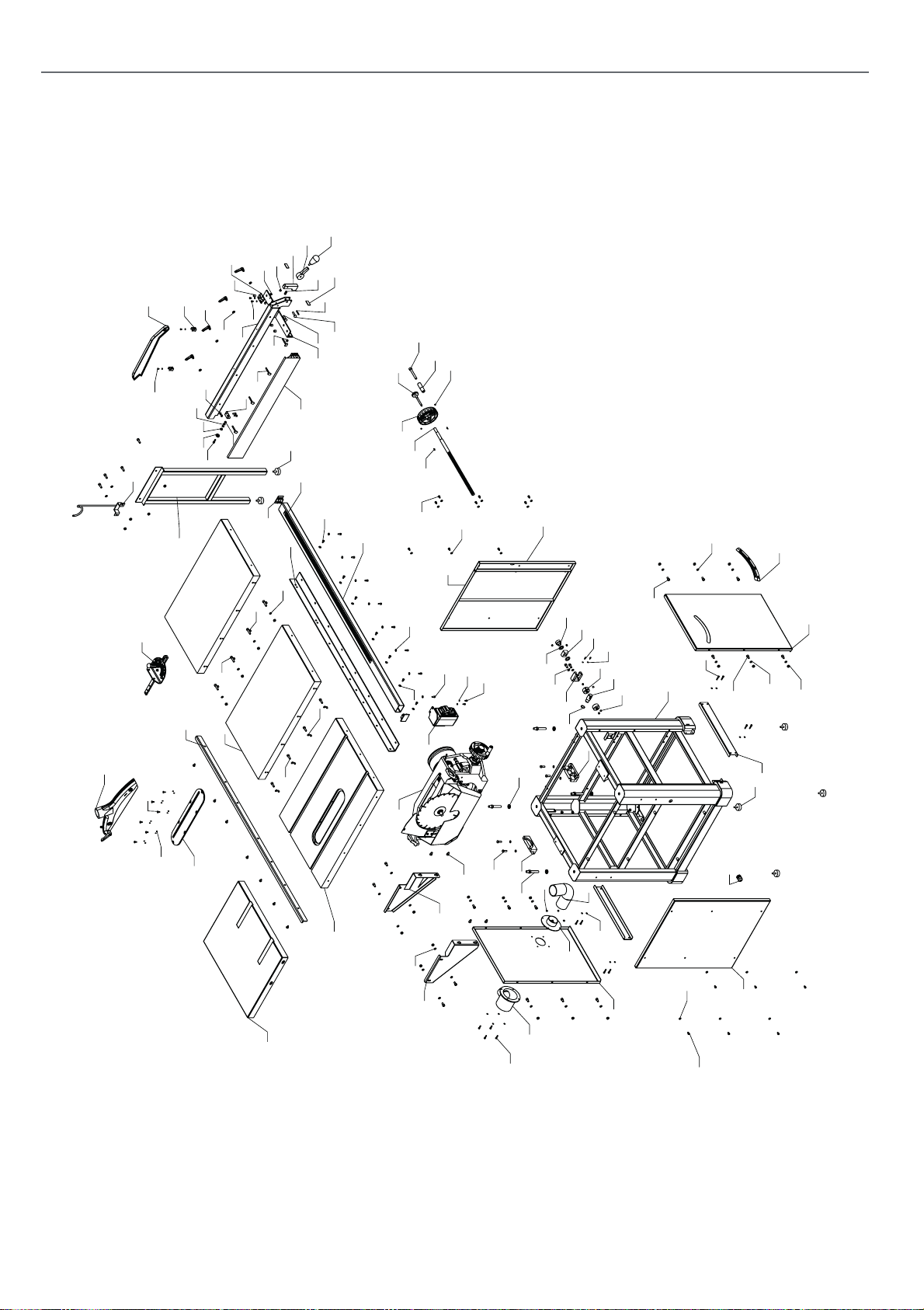
AP305SBD EXPLODED DIAGRAMPARTS LISTS
Diagram/Parts List D
62
60
63
61
82
83
80
81
58
84
93
89
95
39
72
29
66
69
65
68
26
45
23
18
59
76
75
77
70
79
67
25
35
92
44
5774
78
73
58 64
71
27
24
96
22
85
35
87
55
11
54
1
56
8
97
28
29
47
29
Di agr am
31
33
35
53
32
86
7
5
99
43
6
100
14
35
34
41
42
4
9
98
2
88
46
12
49
35
34
36
52
51
Di agr am A
91
90
10
35
16
30
17
15
3
40
13
38
19
33
20
48
21
37
94
29
50
28
30
Page 31
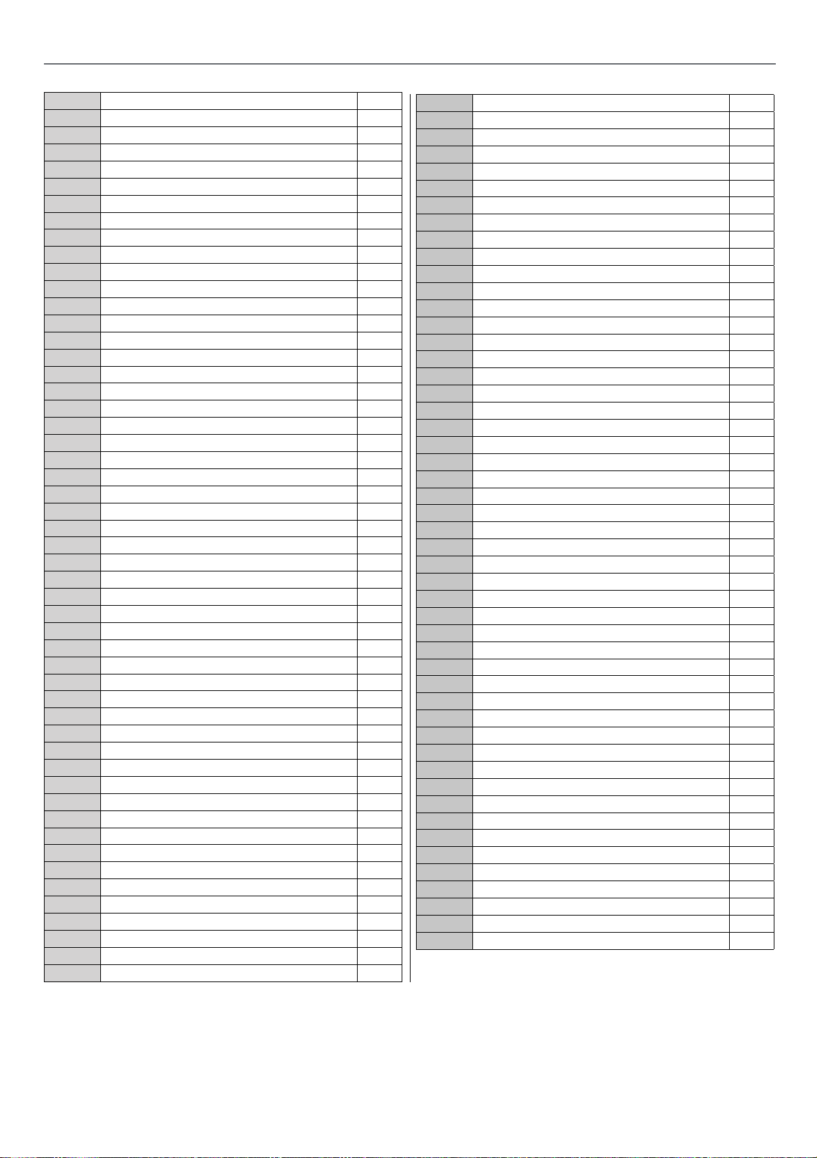
AP305SBD EXPLODED DIAGRAMPARTS LISTS
No. Description QTY
1 Mechanism Assembly 1
2 Rear Trunnion 1
3 Front Trunnion 1
4 Retainer Ring 2
5 Tilt Limit Block 1
6 Mounting Support 1
7 Stopping Hoop 1
8 Tilt Leadscrew 1
9 Tilt Leadscrew Nut 1
10 Worktable 1
11 Locking Nail A 1
12 Angle Scale 1
13 Step Screw 4
14 Big Washer 12 4
15 Supporting Bracket B,Rear Extension Table 1
16 Rear Extension Table 1
17 Supporting Bracket A,Rear Extension Table 1
18 Extension Table 2
19 Dust Collection Hose 1
20 Tie-In A 1
21 Tie-In B 1
22 Support Bracket,Fence Rail 1
23 Rear Fence Rail 1
24 Scale 1
25 End Cap,Front Fence Rail 2
26 Support Leg 1
27 Adjusting Foot Bolt 2
28 Hex.Socket Cap Head Screw M6X10 15
29 Washer 6 25
30 Hex.Socket Cap Head Screw M8X12 4
31 Hex.Socket Cap Head Screw M6X12 10
32 Hex.Socket Cap Head Screw M5X12 2
33 Washer 5 16
34 Hex.Socket Cap Head Screw M8X16 16
35 Washer 8 52
36 Hex.Nut M8 24
37 Hex.Socket Cap Head Screw M5X20 4
38 Hex.Nut M5 4
39 Hex.Socket Countersunk Head M5X16 6
40 Hex.Bolt M8X25 4
41 Hex.Socket Cap Head Screw M4X10 2
42 Washer 4 4
43 Hex.Socket Cap Head Screw M8X20 2
44 Hex.Socket Cap Head Screw M8X25 8
45 Hex.Socket Cap Head Screw M8X35 4
46 Column Frame,Machine Body 1
47 Right Panel,Machine Body 1
48 Rear Panel,Machine Body 1
49 Front Panel,Machine Body 1
50 Left Panel,Machine Body 1
51 Levering Foot 4
No. Description QTY
52 Connecting Board,Machine Body 2
53 Switch 1
54 Handwheel 1
55 Knob 1
56 Hex.Socket Set Screw M6X6 2
57 Pad 2
58 Sling Rail Carrier 1
59 Locking Block 1
60 Locking Cam 1
61 Nylon Screw M12X12 3
62 Fence Lock Knob 1
63 Pointer 1
64 Spring 1
65 Bearing 61900 1
66 Bearing Spacer Bushing 1
67 Bearing Support 1
68 Hex.Socket Cap Head Screw M6X16 1
69 Hex.Nut M6 1
70 Hex.Socket Set Screw M10X10 2
71 Rip Fence 1
72 Hex.Nut M6 2
73 Semi-Round Step Bolt M6X35 1
74 Semi-Round Step Bolt M8X35 1
75 Hex.Self-Locking M6 1
76 Hex.Self-Locking M8 1
77 Cross Recessed Pan Head Screw M5X10 2
78 Spring Pin 5X32 1
79 T-Bolt 4
80 Ratchet Lever 4
81 Big Washer 6 4
82 Push Stick 1
83 Clip 2
84 Cross Recessed Pan Head Screw M4X8 2
85 Rip Fence Rail 1
86 Small Right Panel,Machine Body 1
87 Hex.Socket Cap Head Screw M10X80 1
88 Hex.Socket Cap Head Screw M5X25 8
89 Mitre Gauge Assembly 1
90 Table Insert 1
91 Hex.Socket Set Screw M4X6 12
92 Hex.Socket Set Screw M8X10 8
93 Dust Hose Support 1
94 Cable Gland M20 1
95 Blade Guard Assembly 1
96 Hex.Bolt M8X12 14
97 Semi-Round Key 3X16 2
98 Hex.Socket Set Screw M8X8 6
99 Thrust Washer 30X17X0.8 2
100 Circlip Ring For Shaft 20 1
31
Page 32
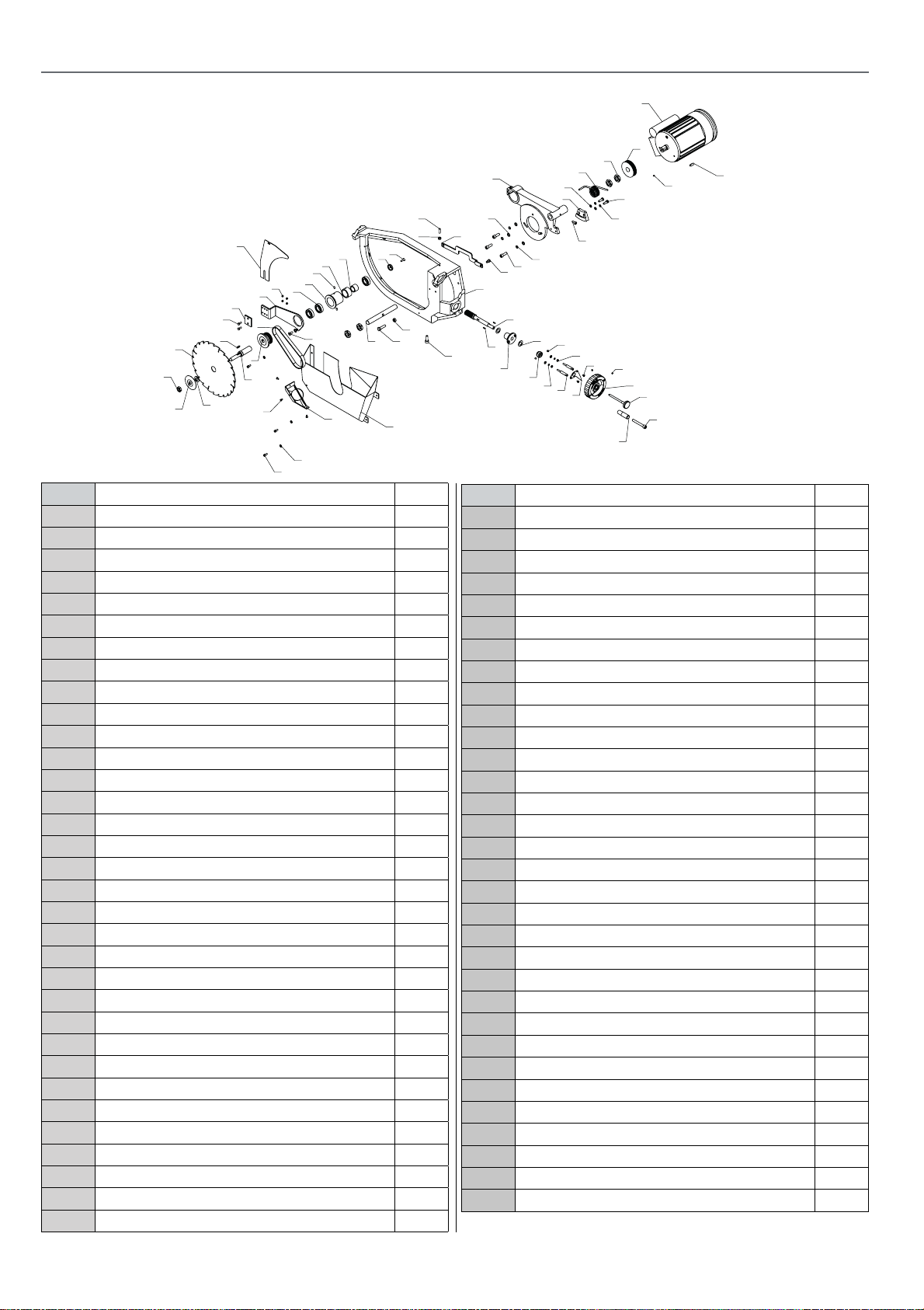
Di agr am B
AP305SBD EXPLODED DIAGRAMPARTS LISTS
Diagram/Parts List E
No. Description QTY
1 Driving Pulley B 1
2 Shaft Pulley 1
3 Arbor Shaft Sleeve 1
4 Arbor Shaft Spacer Bushing 1
5 Arbor Shaft Ending Bushing 1
6 Blade Shaft 1
7 Small Arbor Shaft Spacer Bushing 1
8 Cross Recessed Countersunk Screw M6X20 1
9 Hex.Socket Cap Head Screw M10X30 3
10 Saw Blade 1
11 Riving Knife Bracket 1
12 Semi-Round Key 3X16 2
13 Mounting Base 1
14 Lifting Worm 1
15 Handwheel 1
16 Washer 6 5
17 Shaft 1
18 Thin Nut M22X1.5 4
19 Retaining Hoop 1
20 Locking Nail B 1
21 Press Board,Riving Knife 1
22 Washer 10 4
23 Hex.Socket Countersunk Head M8X20 1
24 Pulling Rod Shaft 1
25 Spring Washer 6 2
26 Hex.Bolt M8X25 2
27 Spring Washer 8 2
28 Washer 8 2
29 Hex.Socket Set Screw M8X6 6
30 Hex.Bolt M8X16 2
31 Spring Pin 6 2
32 Key 5X20 1
33 Motor 1
33
1
18
38
57
41
29
36
11
21
30
39
32
10
46
50
45
2
6
55
56
7
4
31
3
23
16
17
54
58
8
5
49
48
53
22
40
9
24
37
14
12
35
13
19
47
28
34
42
43
29
25
52
26
27
44
63
62
59
51
64
15
20
61
60
65
No. Description QTY
34 Lifting Worm Wheel 1
35 Hex.Socket Cap Head Screw M10X30 2
36 Bearing 6203 3
37 Mounting Base 1
38 Shaft Base 1
39 Driving Belt 1
40 Connection Rod Of Riving Knife Bracket 1
41 Riving Knife 1
42 Spring Washer 10 3
43 Thrust Washer 30X17X0.8 2
44 Hex.Socket Cap Head Screw M8X16 1
45 Arbor Flange 1
46 Thin Nut M16X2(Left) 1
47 Torsion Spring 1
48 Hex.Bolt M10X40 1
49 Hex.Nut M10 1
50 Variable Diameter Sleeve 1
51 Pointer B 1
52 Pointer Seat 2
53 Dust Collection Cover 1
54 Dust Outlet,Dust Collection Cover 1
55 Cross Recessed Pan Head Screw M5X10 3
56 Hex.Socket Cap Head Screw M6X12 3
57 Hex.Socket Flat Head Set Screw M8X10 1
58 Hex.But M8 1
59 Hex.Socket Set Screw M6X6 2
60 Knob 1
61 Hex.Socket Cap Head Screw M10X80 1
62 Cross Recessed Pan Head Screw M5X8 2
63 Thin Nut M6 2
64 Hex.Socket Set Screw M5X6 1
65 Key 8X25 1
32
Page 33
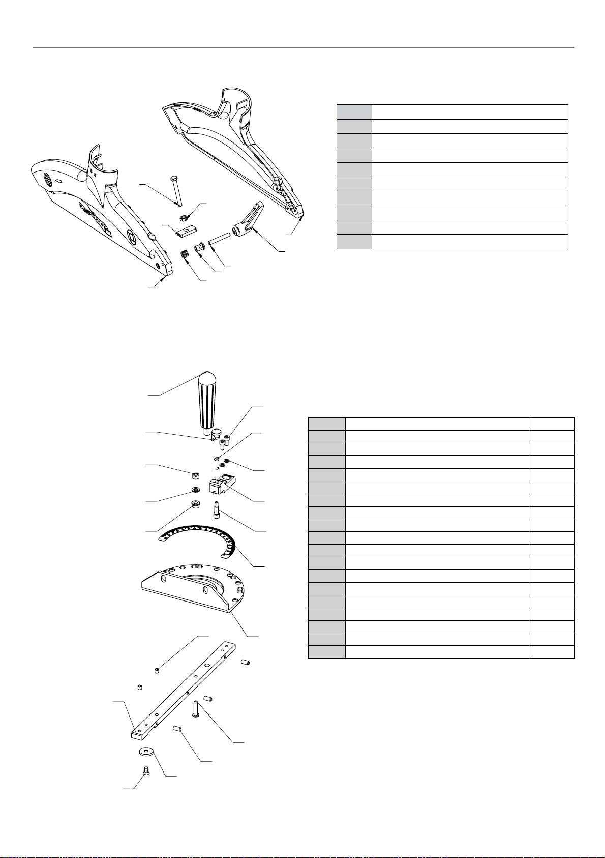
Di agr am C
Diagram/Parts List F
项目号
零件号
数量
1
MJ2320-3-02导向条
1
2
十字槽黑沉头螺钉5X10
1
3
MJ2320-3-10导轨垫
1
4
内六角波子紧定螺钉M6X12
3
5
内六角盘头螺栓M6X20
1
6
内六角紧定螺钉M6X6
2
7
MJ2320-3-01刻度盘
1
8
MJ2320-3-09标尺
1
9
MJ2320-3-06定位轴
1
10
MJ2320-3-03指针座
1
11
弹垫5
2
12
MJ2320-3-07定位弹簧
1
13
内六角圆柱头螺栓M5X12
2
14
MJ2320-3-04锁紧手把
1
15
MJ2320-3-08定位手把
1
16
嵌件自锁螺母M6
1
17
平垫6
1
18
MJ2320-3-05套
1
AP305SBD EXPLODED DIAGRAMPARTS LISTS
No. Description
1 Hex.Nut M6
2 Hex.Socket Flat Head Set Screw M6X40
3 Hex.Bolt M6X15
4 Locking Nut
3
1
4
2
7
5
8
6
9
5 Blade Guard A
6 Blade Guard B
7 Fixed Busing,Blade Guard
8 Inserting Nut
9 Ratchet Lever
Mitre Fence Diagram/Parts List G
14
15
16
17
18
1
2
13
12
11
10
9
8
6
7
5
4
3
No. Description QTY
1 Mitre gauge guide rod 1
2 Cross recessed countersunk screw 1
3 Rail washer 1
4 Hexagon socket set screws M6X12 3
5 Hex.socket pan head screw M6X20 1
6 Hex.socket set screw M6X6 2
7 Mitre gauge base 1
8 Scale 1
9 Stop pin 1
10 Block indicator 1
11 Spring washer 5mm 2
12 Stop spring 1
13 Hex.socket cap head bolt M5X12 2
14 Mitre gauge knob 1
15 Stopping knob 1
16 Self-locking nut M6 1
17 Washer 6mm 1
18 Stop pin 1
33
Page 34
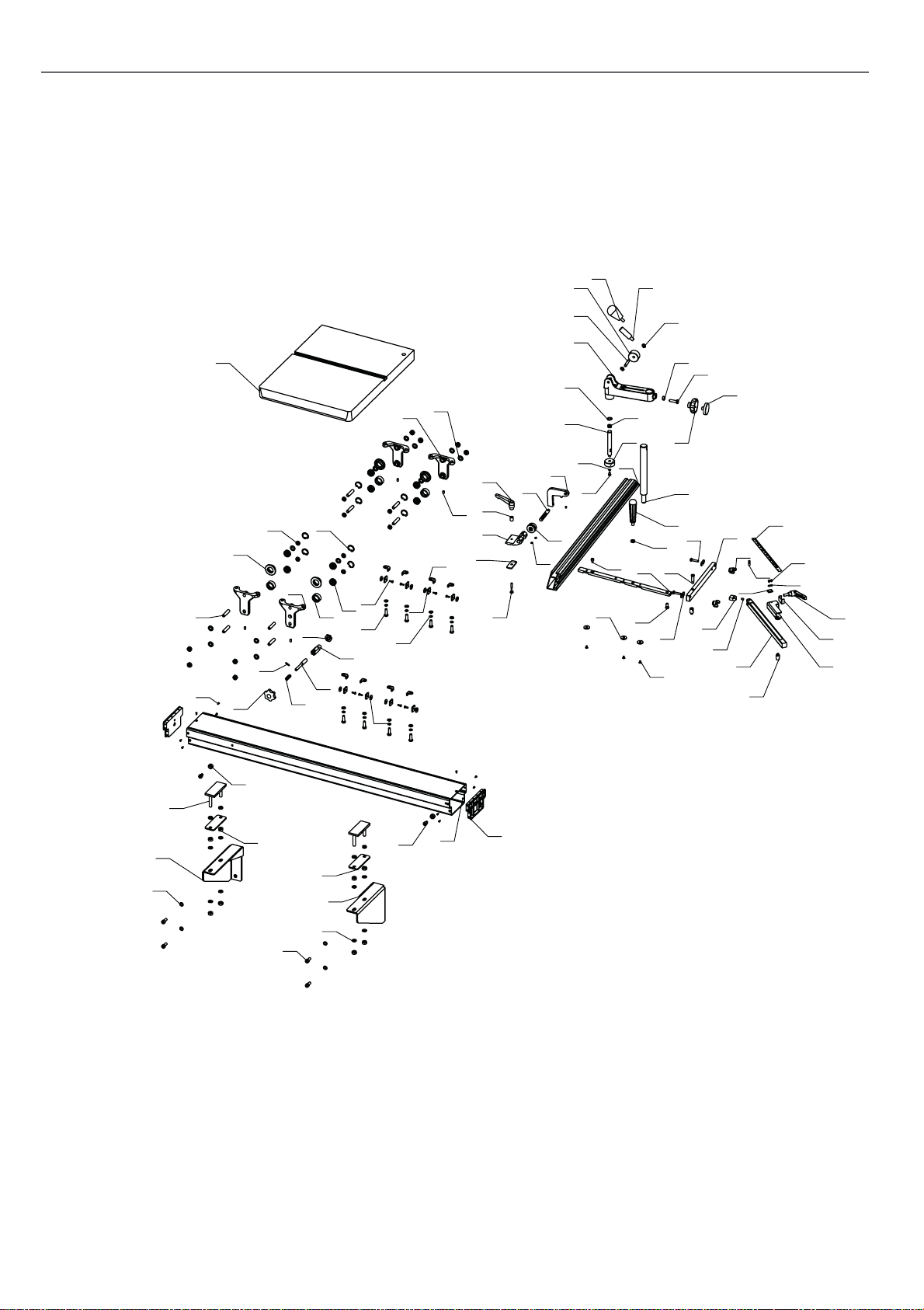
AP305SBD EXPLODED DIAGRAMPARTS LISTS
Diagram/Parts List G
DI AGRAM E OPTI ONAL
55
59
58
61
50
3
82
9
7
79
26
6
46
5
75
19
73
15
77
10
13
16
18
74
76
4
11
14
17
87
64
8
28
27
31
56
81
29
25
80
24
30
62
37
60
54
53
52
23
57
22
51
49
38
34
86
39
20
40
44
83
32
85
43
21
33
66
35
67
84
68
78
41
36
42
72
69
2
65
47
70
1
48
63
45
71
12
34
Page 35
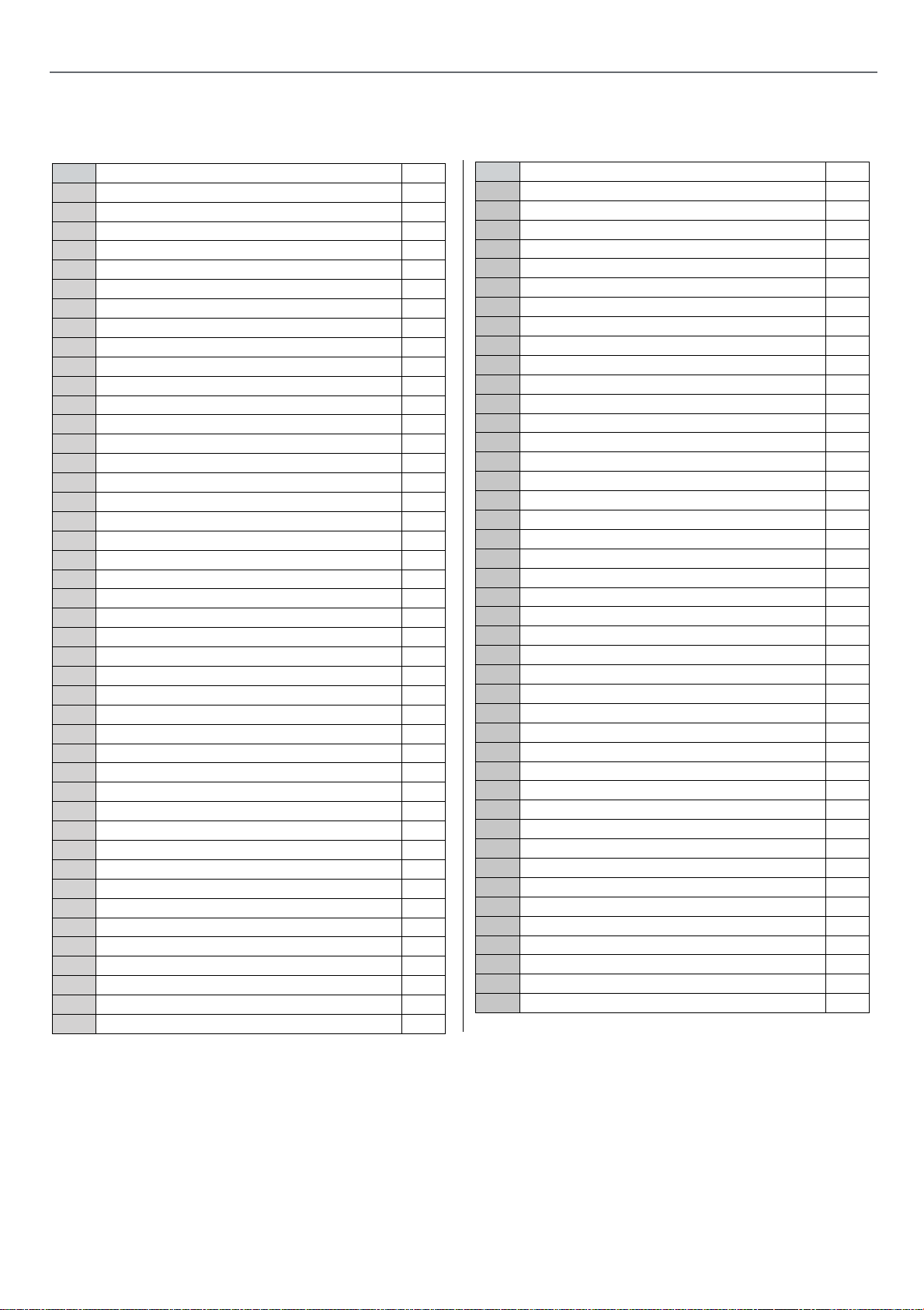
AP305SBD EXPLODED DIAGRAMPARTS LISTS
No. Description QTY
1 Front Supporting Bracket,Sliding Table Rail 1
2 Rear Supporting Bracket,Sliding Table Rail 1
3 Sliding Table 1
4 Roller A 4
5 Roller B 4
6 Hex.Socket Flat End Set Screw M6X10 4
7 Bearing Mounting Base 3
8 Special Big Washer 5 8
9 Washer 10 12
10 Felt Pad Seat 8
11 Hex.Bolt M8X25 8
12 End Cap,Sliding Table Rail 2
13 Bearing Mounting Base 1
14 Fixed Sleeve 1
15 Locking Knob 1
16 Thin Hex.Nut M16 1
17 Fixed Shaft,Sliding Table 1
18 Spring 1
19 Open Cylindrical Pin 1
20 Guide Rail 1
21 Mounting Board,Angle 1
22 Rip Fence,Sliding Table 1
23 Spring 1
24 Fine Adjusting Calibration Wheel 1
25 Stud,Flip Stop 1
26 Ratchet Lever Spcer 1
27 Screw Guide 1
28 Flip Stop Base 1
29 Flip Stop 1
30 Hex.Socket Flat End Set Screw M6X10 3
31 Semi-Round Step Bolt M6X40 1
32 Fixed Pad 2
33 Wing Nut 2
34 Semi-Round Step Bolt M6X35 2
35 Angle Rod 1
36 Locking Sleeve,Angle Rod 1
37 Rail Washer 3
38 Locking Handle 1
39 Long Step Screw 1
40 Step Screw 1
41 Spacer 1
42 Cushion Sleeve 2
43 Angle Scale 1
44 Hex.Socket Countersunk Screw M5X8 3
No. Description QTY
45 Sliding Table Rail 1
46 Thin Hex.Nut M10 12
47 Hex.Nut M10 16
48 Washer 10 8
49 Stud,Hold Down 1
50 Arm,Hold Down 1
51 Locking Knob 1
52 End Cap,Locking Knob 1
53 Hex.Bolt M8X30 1
54 Hex.Nut M8 1
55 Eccentric,Hold Down 1
56 Stud,Hold Down 1
57 Disc,Hold Down 1
58 Screw Rod,Hold Down 1
59 Locking Handle 1
60 Circlips For Shaft 8 2
61 Eccentric Shaft 1
62 Hex.Socket Cap Head Screw M6X10 1
63 Hex.Socket Cap Head Screw M8X20 4
64 Spring Washer 8 12
65 Washer 8 12
66 Pointer 1
67 Cross Recessed Pan Head Screw M4X5 2
68 Washer 4 2
69 Square Bolt 2
70 Spacer,Square Bolt 2
71 Hex.Socket Cap Head Screw M8X12 2
72 Rubber Stopping Sleeve 2
73 Cross Recessed Countersunk Tapping Screw ST3.5X8 10
74 Cross Recessed Pan Head Screw M4X12 8
75 Hex.Socket Flat End Set Screw M10X45 8
76 Deep Groove Ball Bearing 6000-2LS 8
77 Circlips For Hole 47 8
78 Ratchet Lever A 1
79 Ratchet Lever B 1
80 Hex.Socket Cap Head Screw M5X10 1
81 Washer 5 1
82 Circlips For Shaft 14 1
83 Axle Seat 1
84 Round Pin 6X20 1
85 Hex.Socket Flat End Set Screw M6X8 1
86 Thin Hex.Nut M10 1
87 Felt Pad 8
35
Page 36
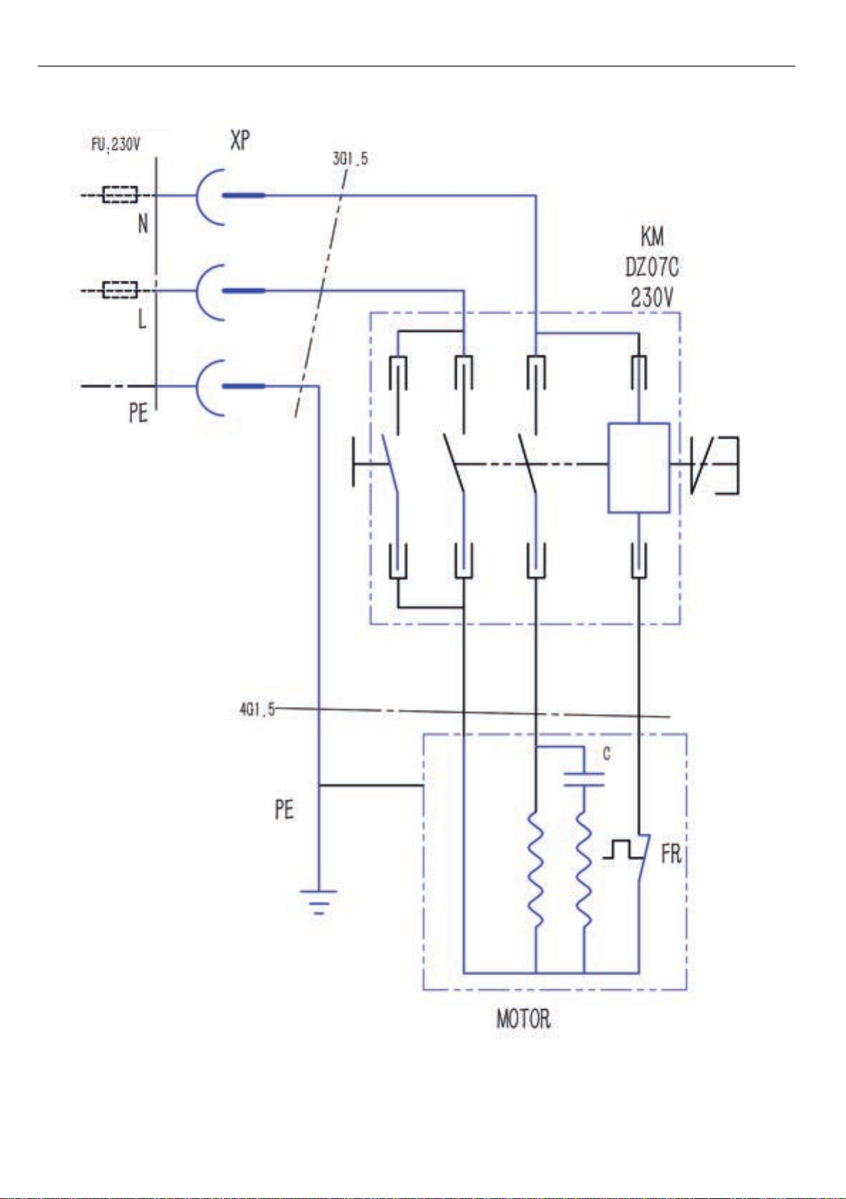
WIRING DIAGRAM
36
Page 37
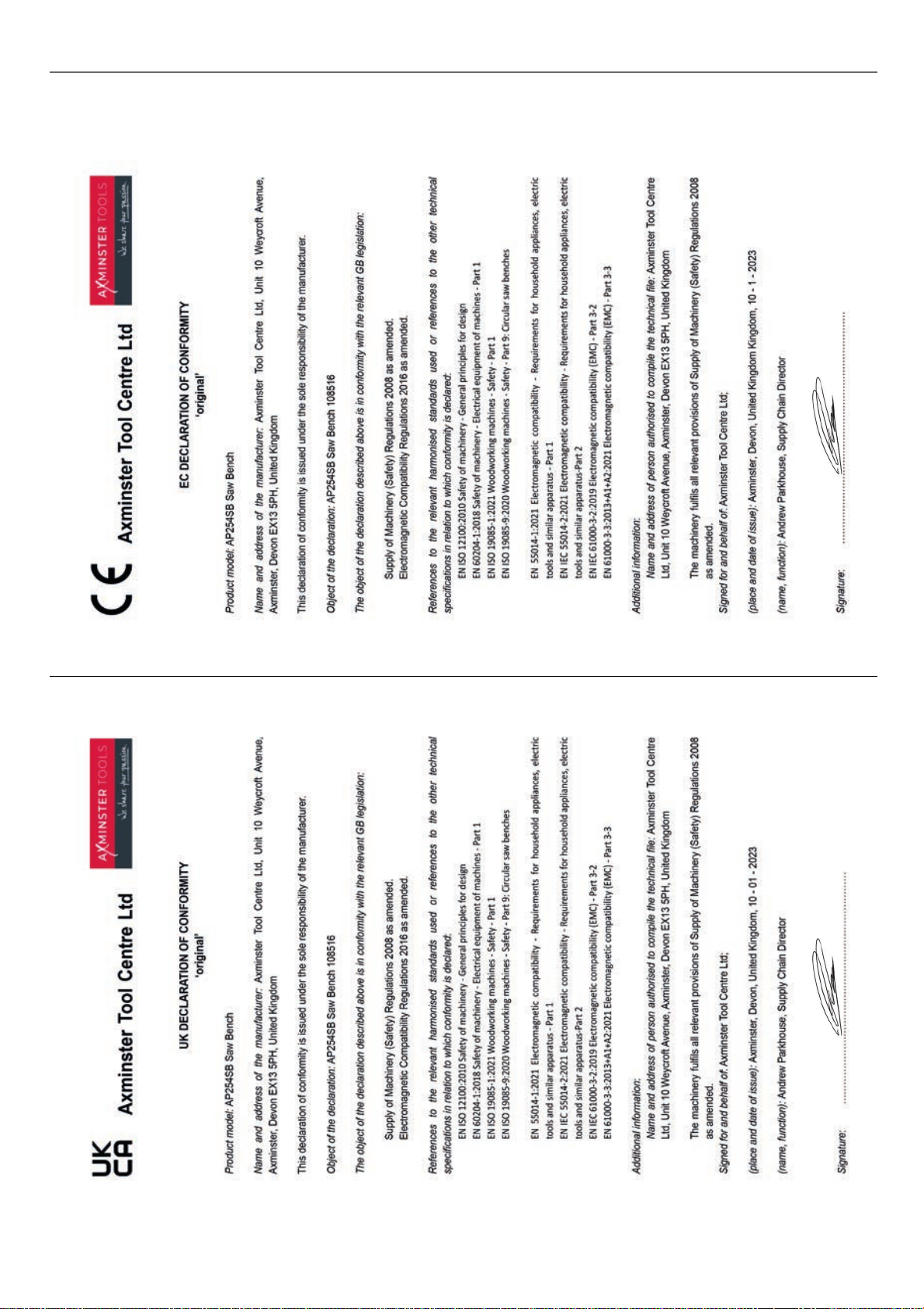
DECLARATION OF CONFORMITY
37
Page 38
DECLARATION OF CONFORMITY
References to the relevant harmonised standards used or references to the other technical specifications in relation
(place and date of issue): Axminster, Devon, United Kingdom Kingdom, 28/6/24
Signature:
(name, function): Andrew Parkhouse, Supply Chain Director
The machinery fulfils all relevant provisions of Supply of Machinery (Safety) Regulations 2008 as amended. Signed for and behalf of: Axminster Tool Centre Ltd;
Additional information:
• ISO 4414:2010 Pneumatic fluid power — General rules and safety requirements for systems and their
• ISO 7960:1995 Airborne noise emitted by machine tools — Operating conditions for woodworking
• ISO 12100:2010 Safety of machinery — General principles for design — Risk assessment and risk
• ISO 13849-1:2015 Safety of machinery — Safety-related parts of control systems — Part 1: General
• ISO 13857:2008 Safety of machinery — Safety distances to prevent hazard zones being reached by upper
• ISO 19085-1:2017 Woodworking machines – Safety – Part-1: common requirements.
• EN 847-1:2017 Tools for woodworking — Safety requirements — Part 1: Milling tools, circular saw blades.
• IEC 60204-1:2005 Safety of machinery — Electrical equipment of machines — Part 1: General
• IEC 61800-5-2:2007 Adjustable speed electrical power drive systems — Part 5-2: Safety requirements —
components.
components.
machines.
reduction.
principles for design.
requirements.
Functional
Name and address of person authorised to compile the technical file: Axminster Tool Centre Ltd, Unit 10
Weycroft Avenue, Axminster, Devon EX13 5PH, United Kingdom.
and lower limb.
to which conformity is declared:
• ISO 19085-9:2020 Part 9: Circular saw benches (with and without sliding table) (ISO19085-9:2019).
• ISO 4413:2010 Hydraulic fluid power — General rules and safety requirements for systems and their
The object of the declaration described above is in conformity with the relevant GB legislation:
Machinery Directive 2006/42/EC
EMC Directive 2014/35/EU
Product model: AP305SBD Table Saw Name and address of the manufacturer: Axminster Tool Centre Ltd, Unit 10 Weycroft Avenue, Axminster, Devon
EX13 5PH, United Kingdom This declaration of conformity is issued under the sole responsibility of the manufacturer. Object of the declaration: AP305SBD Table Saw
Axminster Tool Centre Ltd
EC DECLARATION OF CONFORMITY
‘original’
(place and date of issue): Axminster, Devon, United Kingdom Kingdom, 28/6/24
Signature:
(name, function): Andrew Parkhouse, Supply Chain Director
The machinery fulfils all relevant provisions of Supply of Machinery (Safety) Regulations 2008 as amended. Signed for and behalf of: Axminster Tool Centre Ltd;
Additional information:
• ISO 7960:1995 Airborne noise emitted by machine tools — Operating conditions for woodworking
• ISO 12100:2010 Safety of machinery — General principles for design — Risk assessment and risk
• ISO 13849-1:2015 Safety of machinery — Safety-related parts of control systems — Part 1: General
• ISO 13857:2008 Safety of machinery — Safety distances to prevent hazard zones being reached by upper
• ISO 19085-1:2017 Woodworking machines – Safety – Part-1: common requirements.
• EN 847-1:2017 Tools for woodworking — Safety requirements — Part 1: Milling tools, circular saw blades.
• IEC 60204-1:2005 Safety of machinery — Electrical equipment of machines — Part 1: General
• IEC 61800-5-2:2007 Adjustable speed electrical power drive systems — Part 5-2: Safety requirements —
components.
machines.
Name and address of person authorised to compile the technical file: Axminster Tool Centre Ltd, Unit 10
Weycroft Avenue, Axminster, Devon EX13 5PH, United Kingdom.
requirements.
Functional
reduction.
principles for design.
and lower limb.
References to the relevant harmonised standards used or references to the other technical specifications in relation
to which conformity is declared:
• ISO 19085-9:2020 Part 9: Circular saw benches (with and without sliding table) (ISO19085-9:2019).
• ISO 4413:2010 Hydraulic fluid power — General rules and safety requirements for systems and their
• ISO 4414:2010 Pneumatic fluid power — General rules and safety requirements for systems and their
components.
The object of the declaration described above is in conformity with the relevant GB legislation:
Machinery Directive 2006/42/EC
EMC Directive 2014/35/EU
Name and address of the manufacturer: Axminster Tool Centre Ltd, Unit 10 Weycroft Avenue, Axminster, Devon
Product model: AP305SBD Table Saw
EX13 5PH, United Kingdom This declaration of conformity is issued under the sole responsibility of the manufacturer. Object of the declaration: AP305SBD Table Saw
Axminster Tool Centre Ltd
EC DECLARATION OF CONFORMITY
‘original’
38
Page 39

39
Page 40

Axminster Tools, Axminster Devon EX13 5PH
axminstertools.com
The packaging is suitable for recycling.
Please dispose of it in a responsible manner.
Do not dispose of electric tools together with household waste material.
By law they must be collected and recycled separately.
EU Countries Only
 Loading...