

Page 1
Code 107708
Original Instructions
AT: 7/01/2026 BOOK
VERSION: 08
AP2260BS2
Belt Sander
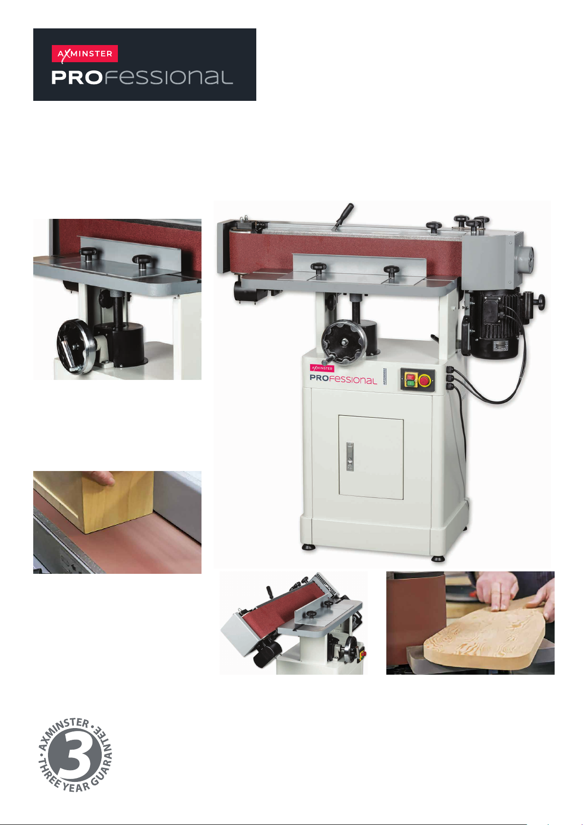
Achieve professional
results
The sanding belt oscillates for a
scratch-free finish and longer
abrasive life.
Sand at any angle
The sanding belt oscillates for a
Whether you need to sand vertically,
horizontally or any angle in between,
this belt sander is the perfect choice!
Need to carry out curved
work?
The sanding belt oscillates for a
Thanks to the small sanding table,
curved work is a breeze.
Easy to use
The sanding belt oscillates for a With
rack & pinion table adjustment, it is
quick and easy to move the table to
where you need it.
Page 2
Page 3

1. Safety
WARNING
Some dust created by power sanding, sawing, grinding, drilling, and other construction activities
may contain chemicals, including lead, birth defects, or other reproductive harm. Wash hands after
handling. Some examples of these chemicals are:
• Lead from lead-based paints.
• Crystalline silica from bricks, cement, and other masonry products.
• Arsenic and chromium from chemically treated lumber.
Your ri sk fr o m t he se ex po su re s va ri es de pe nd in g o n ho w o ft en you do th i s t yp e o f wo rk . To re du ce
your exposure to these chemicals, work in a well-ventilated area with approved safety equipment
such as dust masks specially designed to filter out microscopic particles.
This operating instructions
▲explains the meaning and use of the warning notes included in the operating instructions
▲points out the dangers that might arise for you or others if these instructions are not
observed.
▲informs you how to avoid dangers.
In addition to these operation instructions, please observe
▲the applicable laws and regulations
▲the statutory provisions for accident prevention
▲the prohibition, warning and mandatory signs as well as the warning notes on the machine.
If required, the relevant measures to comply with the country-specific regulations must be taken
before commissioning the machine.
Always keep this manual close to the machine.
1.1 Safety instructions for general machinery
The purpose of safety symbols is to attract your attention to possible hazardous conditions. This
manual uses a series of symbols and signal words intended to convey the level of importance of the
safety messages. The progression of symbols is described below. Remember that safety messages
by themselves do not eliminate danger and are not a substitute for proper accident prevention
measures.
2
Page 4

For your own safety, read instruction manual before operating the machine. Learn
the machine’s application and limitations as well as the specific hazards peculiar.
Always wear approved safety glasses or a face shield when operating or observing
machinery to reduce the risk of eye injury or blindness from flying particles.
Eyeglasses are not approved safety glasses.
Dust created while using machinery may cause cancer, birth defects, or long-term
respiratory damage. Be aware of dust hazards associated with each workpiece
material, and always wear an approved respirator to reduce your risk.
Always wear hearing protection when operating or observing loud machinery.
Extended exposure to this noise without hearing protection can cause permanent
hearing loss.
Keep hands and clothing away from moving parts. Always tie back or cover long hair.
Wear non-slip footwear to avoid accidental slips which could cause a loss of
workpiece control.
1.2 Safety instructions for sanding machine
READ MANUAL. This manual contains proper operating and safety procedures for this
machine.
WORKPIECE PRESSURE. Do not jam the workpiece against the sanding surfaces.
Firmly grasp the workpiece in both hands and ease it against the belt/spindle using light pressure.
CLOTHING. Do not wear loose clothing or jewelry while operating this machine. Roll up or button
sleeves at the cuff, and tie back long hair.
HAND PLACEMENT. Do not place hands near, or in contact with, sanding surfaces during
operation.
WORKPIECE HANDLING. Grip the workpiece with both hands, or the workpiece may be thrown
from machine and cause serious personal injury.
MAINTENANCE. Perform machine inspections and maintenance promptly as required.
UNATTENDED MACHINE. Never leave the machine running unattended.
SANDING BELTS/DRUMS. Replace sanding belts and drums promptly as needed.
WORKPIECE QUANTITY. Never sand more than one piece of stock at a time.
FOREIGN MATERIAL. Always inspect stock for nails, staples, knots, and other imperfections that
could be dislodged and thrown from the machine during sanding operations.
DUST COLLECTION. Never operate the sander without an adequate dust collection system in
place and running.
DIRECTION. Never sand tapered or pointed stock with the point facing the feed direction, or the
workpiece may be thrown from machine and cause serious personal injury.
POWER DISCONNECT. Disconnect the machine from the power source before changing the
sanding belt or sleeve.
3
Page 5

1.3 Safety check
Check all safety devices when starting any task, once a week and after any maintenance
and repair work. Close all protective covers before starting the machine.
Safety during operation
We specifically point out the dangers in the description of work with and on the sanding
machine.
▲
DO NOT leave a gap between wood and back stop, and keep hands away from
belt.
▲
DO NOT sand wood with fingers close to spindle.
▲
DO NOT sand wood with sharp corners at the leading-edge of the sanding operation. The
belt can grab and throw the wood.
▲
ALWAYS use the back stop, and keep fingers away from the belt.
▲
ALWAYS keep your fingers away from the spindle.
▲
ALWAYS sand wood with sharp corners at the trailing-edge of the sanding operation.
Avoid any unsafe work methods:
2. Technical Specification
The following information represents the dimensions and weight information and the manufacturer‘s
approved machine data.
Specification
01) Work table size (mm): 750x250
02) Table travel (mm): 80 (up and down)
03) Belt size (mm): 2260x150
04) Belt table size (mm): 820x170
05) Belt table tilt (mm): 0 -90°
06) Dust chute diameter (mm):100
07) Motor (W): 2200W
3. Assembly
3.1 Placement location
Transport the sanding machine in its packing crate to a place near its final installation
site before unpacking it. If the packaging shows signs of possible transport damage, take
the necessary precautions not to damage the machine when unpacking. If any damage,
the carrier must be notified of this fact immediately to establish any claim which might
arise.
4
Page 6
3.2 Electrical Grounding Instructions
This sander must be grounded while in use to protect the operator from electric
shock.
In the event of a malfunction or breakdown, grounding provides a path of least
resistance for electric current to reduce the risk of electric shock. This tool is equipped with an
electric cord having an equipment-grounding conductor and a grounding plug. The plug must be
plugged into a matching outlet that is properly installed and grounded in accordance with all local
codes and ordinances.
Do not modify the plug provided. If it will not fit the outlet, have the proper outlet installed by a
qualified electrician. Improper connection of the equipment-grounding conductor can result in a risk
of electric shock. The conductor, with insulation having an outer surface that is green with or without
yellow stripes, is the equipment grounding conductor. If repair or replacement of the electric cord or
plug is necessary, do not connect the equipment-grounding conductor to a live terminal.
Check with a qualified electrician or service personnel if the grounding
instructions are not completely understood, or if in doubt as to whether the tool is
properly grounded. Use only three wire extension cords that have three-prong
grounding plugs and three-pole receptacles that accept the tool’s plug.
Repair or replace a damaged or worn cord immediately.
3.3 Assembly
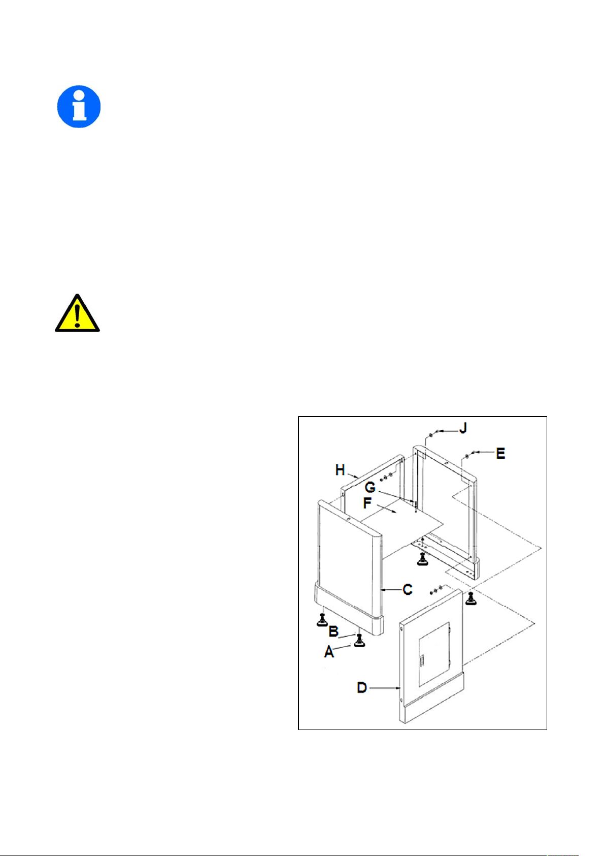
3.31 Stand Assembly
1. Remove all contents from the shipping
cartons.
2. Clean all rust protected surfaces with a mild
solvent. Do not use paint or lacquer thinner,
gasoline, or mineral spirits; these will damage
painted surfaces.
3. Attach the four rubber pads (A) to t
bottoms of the side panels (C) with four each
hex nuts (B). The hardware can be found in the
bag with the rubber pads.
4. Attach the side panels (C) to the front panel
(D) with four 5/16” x 5/8” hex cap screws, eight
5/16” flat washers, four 5/16” lock washers,
and four 5/16” hex nuts (E). Hand tighten the
hardware at this point.
Note: Assemble the stand upside down to
make sure that the tops of the panels are flush.
5. Mount the shelf (F) to the inside of the stand
with two M5x10 pan head screws, two M5 flat
washers and two M5 lock washers (G).
6. Finish the stand assembly by attaching the rear panel (H) to side panels (C) with four 5/16” x 5/8”
hex cap screws, eight 5/16” flat washers, four 5/16” lock washers, and four 5/16” hex nuts (J).
7. Make sure stand is sitting evenly on a level surface before tightening hardware.
he
5
Page 7
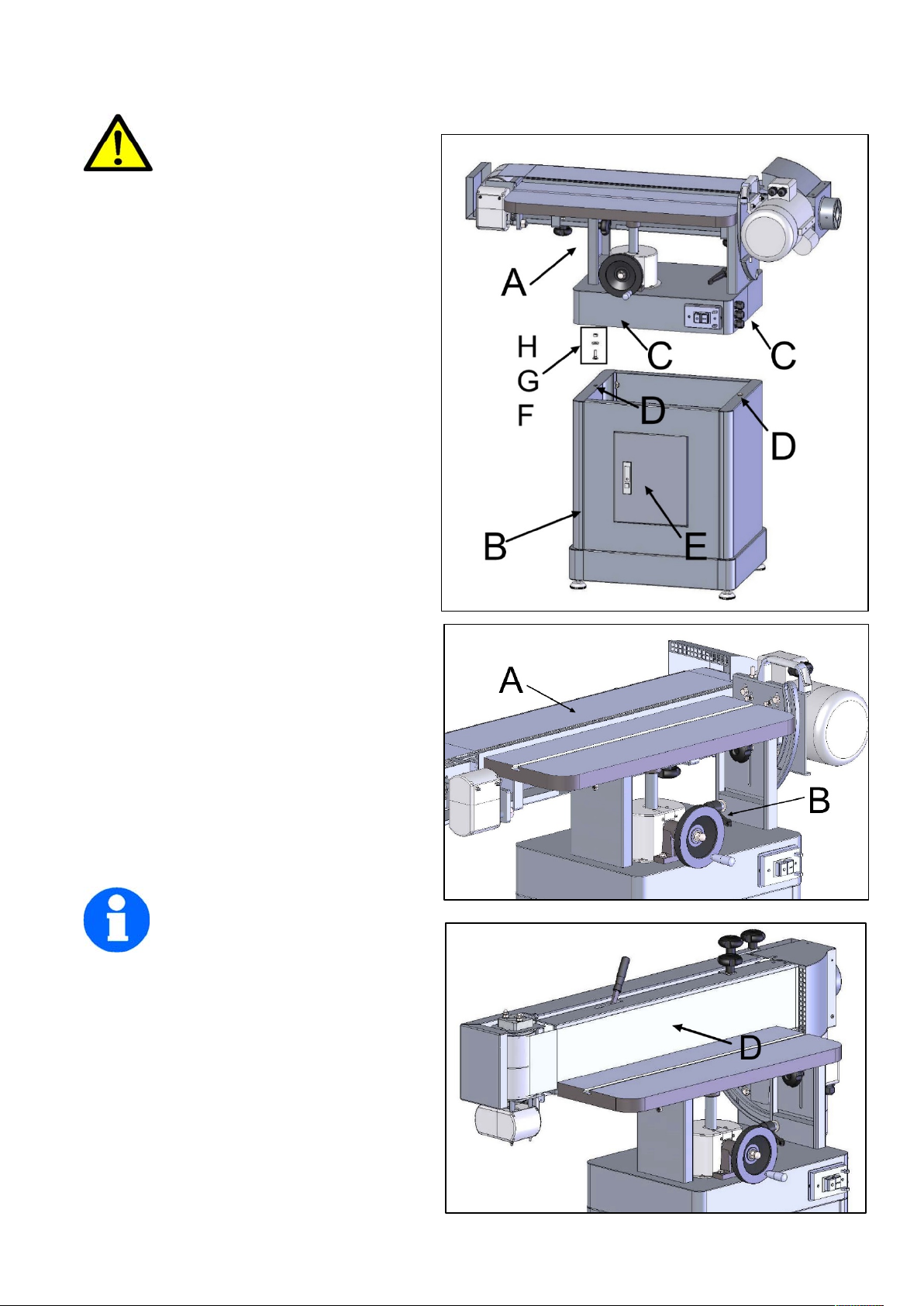
3.32 Installing Table and Motor Unit to Stand
The Table and Motor Unit is
heavy! Use great care and
adequate resources when lifting
the unit up onto the stand! Failure to comply
may cause serious injury and/or damage to
the sander and/or property!
1. With the aid of another person, carefully lift
the table and motor unit (A) out of the shipping
box, and up onto the stand (B).
2. Line up threaded holes in the base (C) with
the holes in the stand (D).
3. Open the cabinet door (E) and through the
opening attach main unit to stand with two
5/16” x 1-1/4” hex cap screws (F), two 5/16”
lock washers (G) and two 5/16” flat washers
(H). Tighten with a 12mm wrench.
4. The sanding platen (A) is presently in the
horizontal position. Pull lock handle (B)
forward to unlock the platen assembly.
5. Tilt sanding platen to the vertical position,
which will look like D; then push the lock
handle (B) to lock the platen assembly in
place.
Note: Do not turn the lock
handle. Turning or rotating the
lock handle will change the
tension of the locking assembly. This may
cause the locking assembly not to work,
making it necessary for adjustment before
using the machine.
6
Page 8
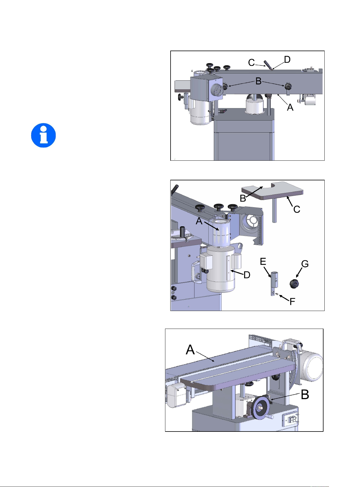
3.33 Sanding Belt Installation
1. From the rear of the sander, remove the belt guard (A) by unscrewing two lock knobs (B).
Take out the sanding belt and removable fence
from behind the belt guard.
2. Place the handle (C) on belt tensioning lever
(D). Remove the tension from the mechanism by
moving the handle (C) to the Loose position.
3. Place belt on both rollers so that the edge of
the belt is even with the edge of the rollers.
Note: Make sure that direction arrow on belt
matches the direction indicator on
the top of the platten.
4. Tighten the belt by moving the
tension arm handle (C) to the Tight position.
Rotate the belt by hand in the direction indicated
by the arrow on top of the platten. If the belt tracking needs adjustment, see Belt Tracking Adjustment.
3.34 Extension Table
1. Attach the bracket (E) for the extension table
to the side of the motor housing (D) and secure
with two socket head cap screws (F).
2. Slide the shaft of the extension table (C) into
the bracket (E), positioning the table so the
opening (B) wraps around the drive drum (A).
3. Insert lock knob (G) into the threaded hole on
the side of the bracket (E) visible from the rear
of the sander.
4. Adjustment
4.1 Sanding Platen Angle Adjustment
1. Disconnect the machine from the power
source.
2. Pull the lock handle (B) forward (unlock) to
release tension.
Move the sanding platen (A) to the desired
position. Use a combination square between
the table and sanding platen to get precise
angles.
3. Hold the platen (A) while locking the handle.
7
Page 9
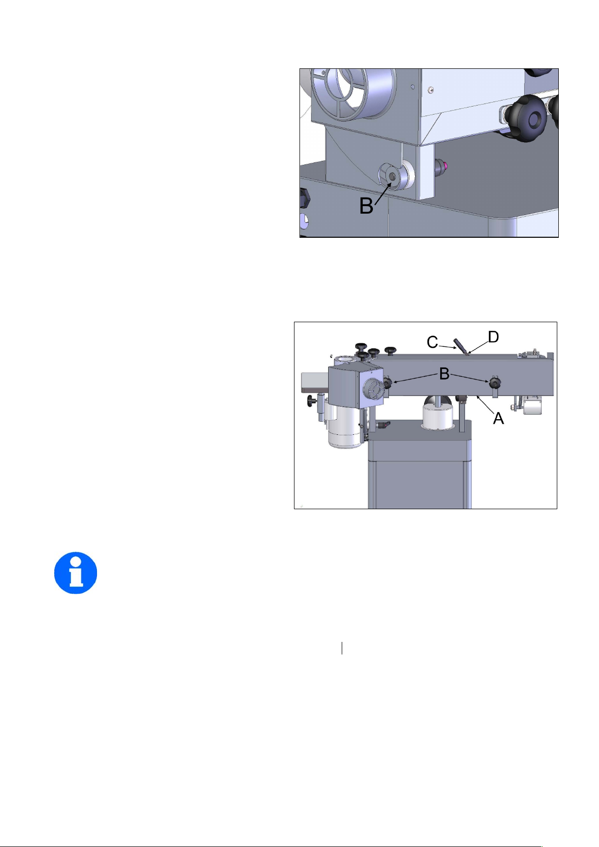
4.2 Platen Lock Tension Adjustment
1. Disconnect the machine from the power
source.
2. Loosen (unlock) the handle (B in 4.1) and
place the platen in the horizontal position as
shown in (A in 4.1). Do not lock.
3. Tension eccentric block by tightening the nut
(B) with a 14mm wrench. Turn the nut in by 1/4
turn increments and test locking handle for
proper tension.
The lock handle is properly tensioned when it
requires positive force to move the eccentric block (attached to the locking handle) from one side to
the other. The platen and motor assembly must stay in a locked position without sliding once the
handle has been moved to the locked position. Re-adjust as necessary.
4.3 Changing the Sanding Belt
1. Disconnect the machine from the power
source.
2. Lock the sanding platen in the vertical
position (see the Sanding Platen Angle
Adjustment section).
3. Release tension on the belt by loosening
the handle (C).
4. Loosen or remove the lock knobs (B) and
remove the belt guard (A).
5. Remove the old belt and install the new belt
matching the direction of the arrows on the belt
with the arrow label on the top of the platen.
6. Line up edge of belt with edge of rollers.
7. Place tension on the belt by moving the tension arm handle (C) to the Tight position.
8. Reinstall the belt guard (A) and tighten the lock handles (B)
Note: Belts stretch with wear. When a belt is replaced, you may have to adjust
tracking.
4.4 Belt Tracking Adjustment
The Belt Tracking Adjustment is a fine adjustment procedure. The Motor Mount Tracking
Adjustment (following section) is a course adjustment.
To adjust the belt tracking:
1. Disconnect the machine from the power source.
2. Push the belt by hand from left to right (the direction indicated top of the platen) and observe the
belt’s position on the rollers. The oscillating movement of the belt is by design.
8
Page 10
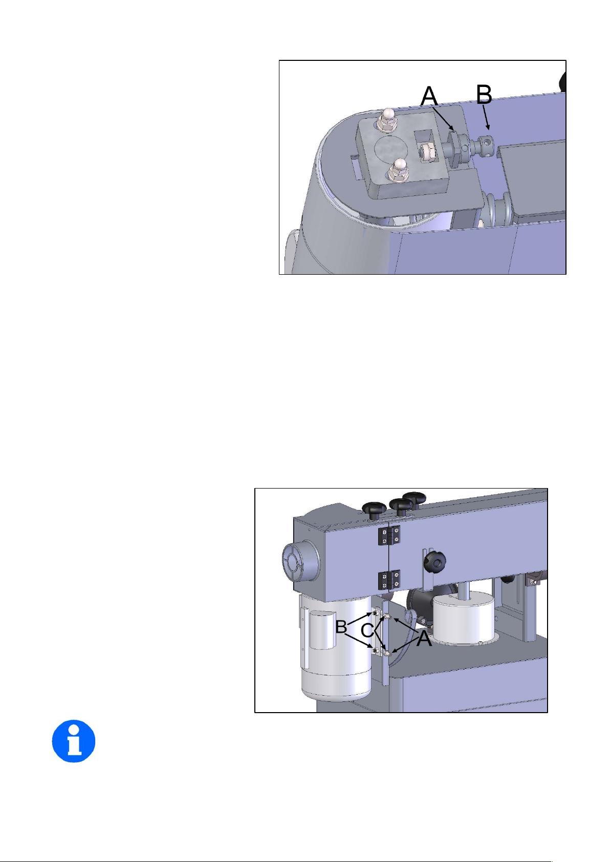
Observe the belt's range of movement
from its highest to lowest position. The
edges of the belt should not have a
tendency to move above or below the
edges of the rollers.
If adjustment is still necessary:
3. Insert the round shaft of the belt
tracking tool (provided) into the micro
adjust lock nut (A) and turn away from you
to loosen.
4. Turn the micro adjusting screw (B) in
1/4 turn increments until the belt tracks
evenly on the rollers when rotated by
hand.
Tip: Moving the belt tracking tool away from you raises the belt on the drum and towards you lowers
the belt on the drum.
5. Tighten the micro adjusting nut (A).
6. Connect the machine to power.
7. Turn on the power to the machine and observe the belt’s up and down range of movement.
Adjustment is correct when the edges of the belt do not move above or below the edges of the
rollers.
8. When adjustment is complete, tighten the micro adjust lock nut (A).
If the tracking cannot be corrected go to the Motor Mount Tracking Adjustment section.
4.5 Motor Mount Tracking Adjustment
This machine comes with tracking adjustment bolts (A) on the motor plate. These are set at the
factory and should not require any
further adjustment. If, however, you
are not able to track the belt with the
Belt Tracking Adjustment described in
the previous section, the motor mount
bolts will have to be adjusted.
Note: The Motor Mount Tracking Adjustment is a course adjustment. Use the Belt
Tracking Adjustment first for fine adjustment. If it cannot be adjusted, then use the
procedure described below.
9
Page 11
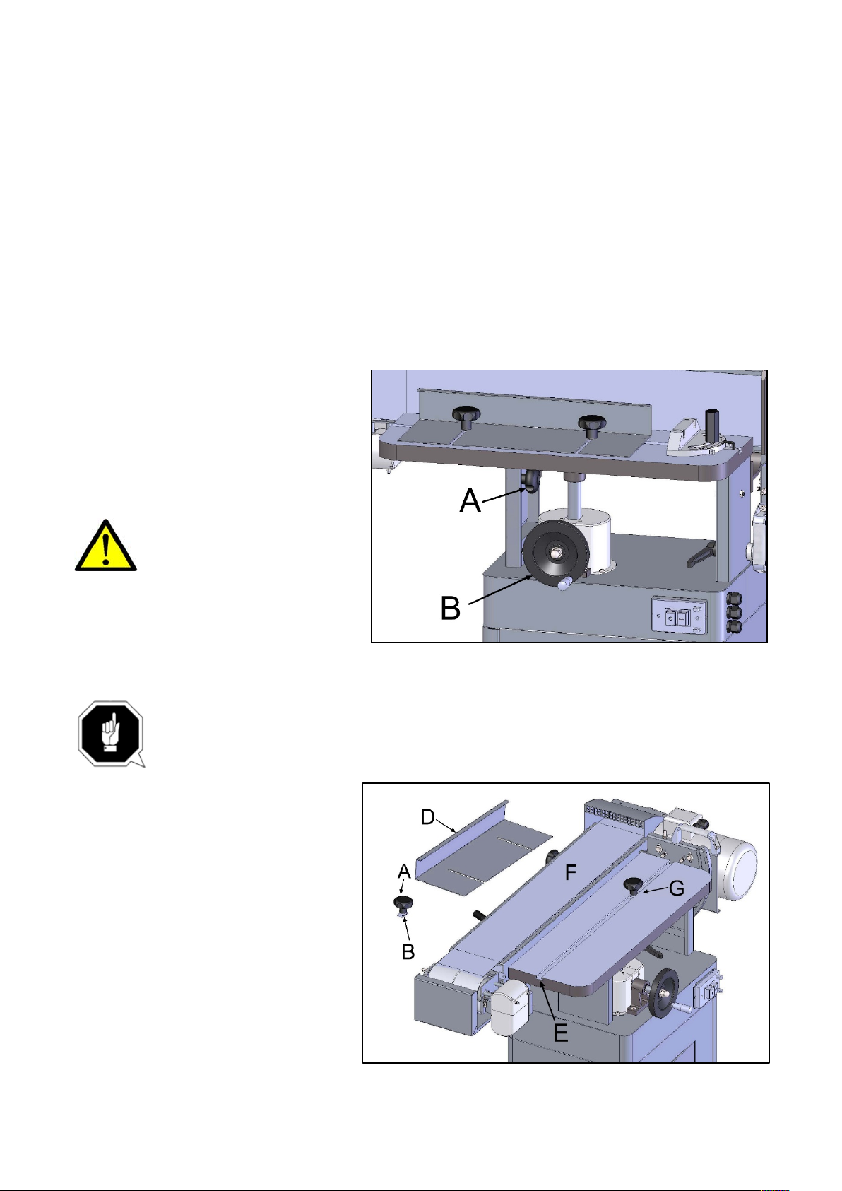
To adjust:
1. Disconnect the machine from the power source.
2. Slightly loosen the four motor mount nuts (B) just enough so the tracking screws (A) can be
turned to make an adjustment.
3. Loosen the two locking hex nuts (C) that secure the tracking screws (A).
4. Turn one screw (A) a 1/4 turn and rotate the sanding belt by hand to observe which direction the
adjustment is causing the belt to move. If it is traveling in the direction needed to correctly track the
belt go to step 6.
5. If the belt starts to travel in the wrong direction, back off a quarter turn and tighten the other screw
a quarter turn. This should start the belt moving in the proper direction.
6. Tighten both locking nuts (C) and motor mount nuts (B). Then return to the Belt Tracking
Adjustment section and again attempt to fine tune the tracking.
4.6 Table Adjustment
1. Loosen two lock knobs (A).
2. Raise or lower work table by the
handwheel (B) to desired level.
3. Tighten two lock knobs.
Do not position table below
sanding belt! Keep an
overlap of at least 1/16”
between table and sanding belt to
avoid material and/or fingers getting
caught!
5. Operation
Removing the belt guard exposes more of the sanding belt! Replace the belt guards
immediately after completing any sanding that requires its removal! Failure to comply
may cause serious injury
5.1 Horizontal Sanding
For horizontal sanding, the platen is
locked in the horizontal position as
shown (F) and the removable fence (D)
is secured to the table (E) as follows.
Place 5/16 flat washers (not shown)
and guide blocks (B) on two 12mm lock
knobs (A)
Note: the 12mm refers to the
threaded shaft length.
10
Page 12
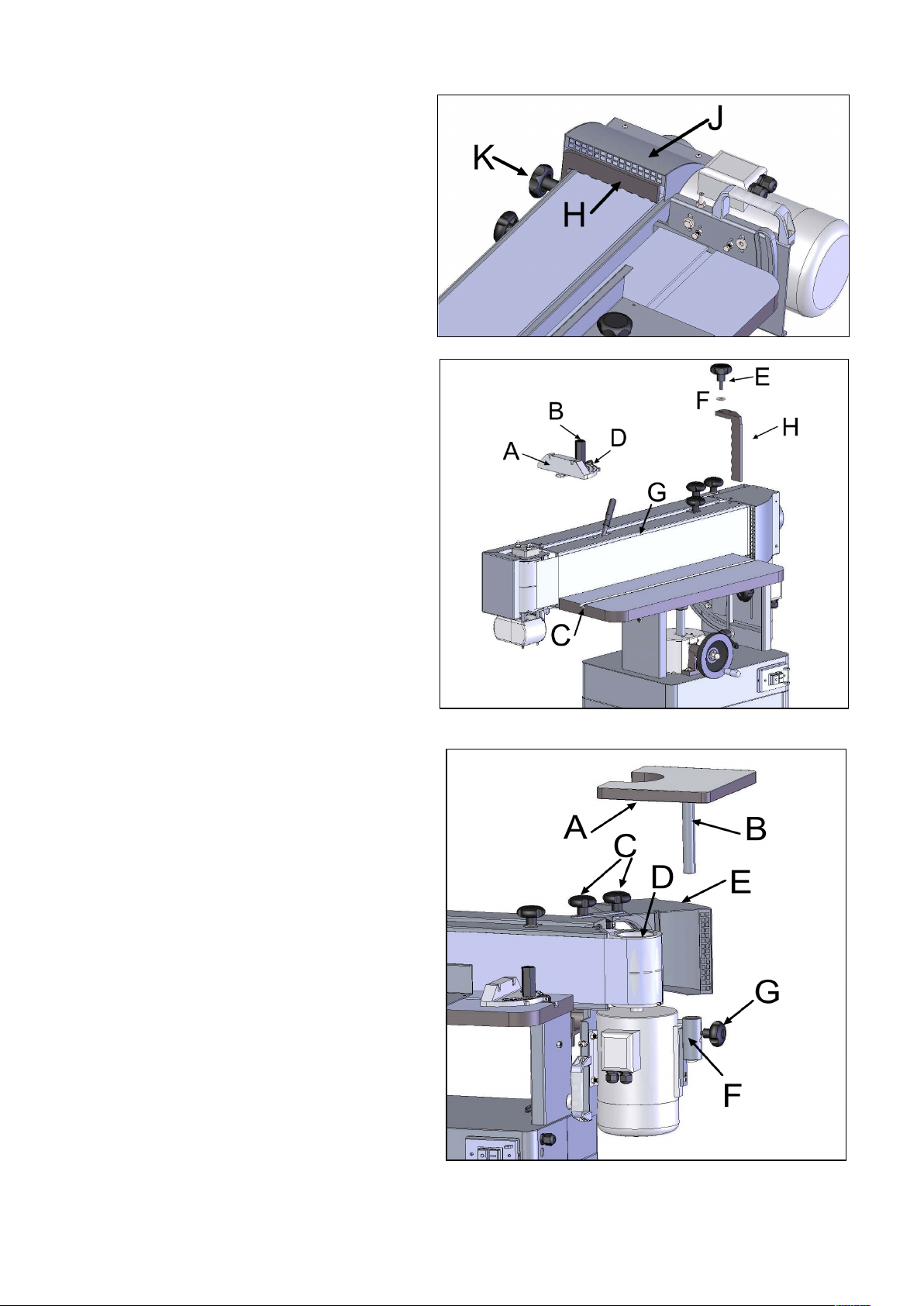
2. Insert the guide blocks (B) into the miter
slot (C) and position the lock knobs (G) on
the table (E) as shown.
3. Place the removable fence (D) on the
table and secure by tightening the lock
knobs (G).
The backstop (H) can also be used by
swiveling the drum guard & dust port (J) out
of the way and placing the backstop pin in
the positioning hole and securing in place
with the lock knob (K) and 5/16" flat washer.
5.2 Vertical Sanding
For vertical sanding, the platen (G) is locked
in the vertical position as shown and the
backstop (H) and/or the miter gauge (B) may
be used.
Miter Gauge
1. Slide the guide bar (D) of the miter gauge
(A) into the miter slot (C) on the table.
2. Set the miter angle; then secure the miter
by tightening the lock handle (B).
Backstop
Place the backstop pin in the positioning
hole and secure in place with the lock knob (E) and 5/16" flat washer (F).
5.3 Contour Sanding
Contour sanding is done from the extension
table mounted on the motor where the sanding
belt wraps around the drive drum (D).
To set up the sander for contour sanding:
1. Loosen the two lock knobs (C) that secure the
drum guard & dust port (E).
2. Swing the end guard (E) back, bringing the
drive drum (D) into view.
3. Tighten the lock knobs (C).
4. Mount the extension table (A) to the sander by
inserting the post (B) into the bracket (F).
5. Set the table to the desired height, then secure
into position by tightening the lock knob (G).
Important: When the extension table (B) is not
in use, the drum guard & dust port (E) should
always be in the closed position so the drive drum (D) is not in view.
11
Page 13

6. Troubleshooting
Trouble
Possible Cause
Possible Solution
Sander will not start
1. Sander unplugged from wall or motor
2. Fuse blown or circuit breaker tripped
3. Cord damaged
1. Check all plug connections
2. Replace fuse or reset circuit breaker
3. Replace cord
Sanding belt does
not come up to speed
1. Extension cord too light or too long
2. Motor not wired for proper voltage
3. Low current
1. Replace with adequate size and length
cord
2. Refer to motor junction cover for proper wiring
3. Contact a qualified electrician
Machine vibrates
excessively
1. Stand on uneven floor
2. Motor mounts are loose
3. Tension spring is worn or broken
1. Adjust stand so that it rests evenly on the floor
2. Tighten motor mount bolts
3. Replace spring
Abrasive belt keeps
tearing
1. Belt is running in the wrong direction
1. Arrow on the sanding belt and machine
should be pointing in the same direction.
Sanded edge not
square
1. Table not square to sanding platen
1. Use a square to adjust table to sanding platen
Sanding marks on
wood
1. Wrong grit sanding belt
2. Feed pressure too great
3. Sanding against the grain
1. Use coarser grit for stock removal and fine grit
for finish sanding.
2. Never force work into sanding platen
3. Sand with the grain
Before carrying out any fault service or maintenance work always:
1. Turn machine OFF
2. Unplug power cable
12
Page 14
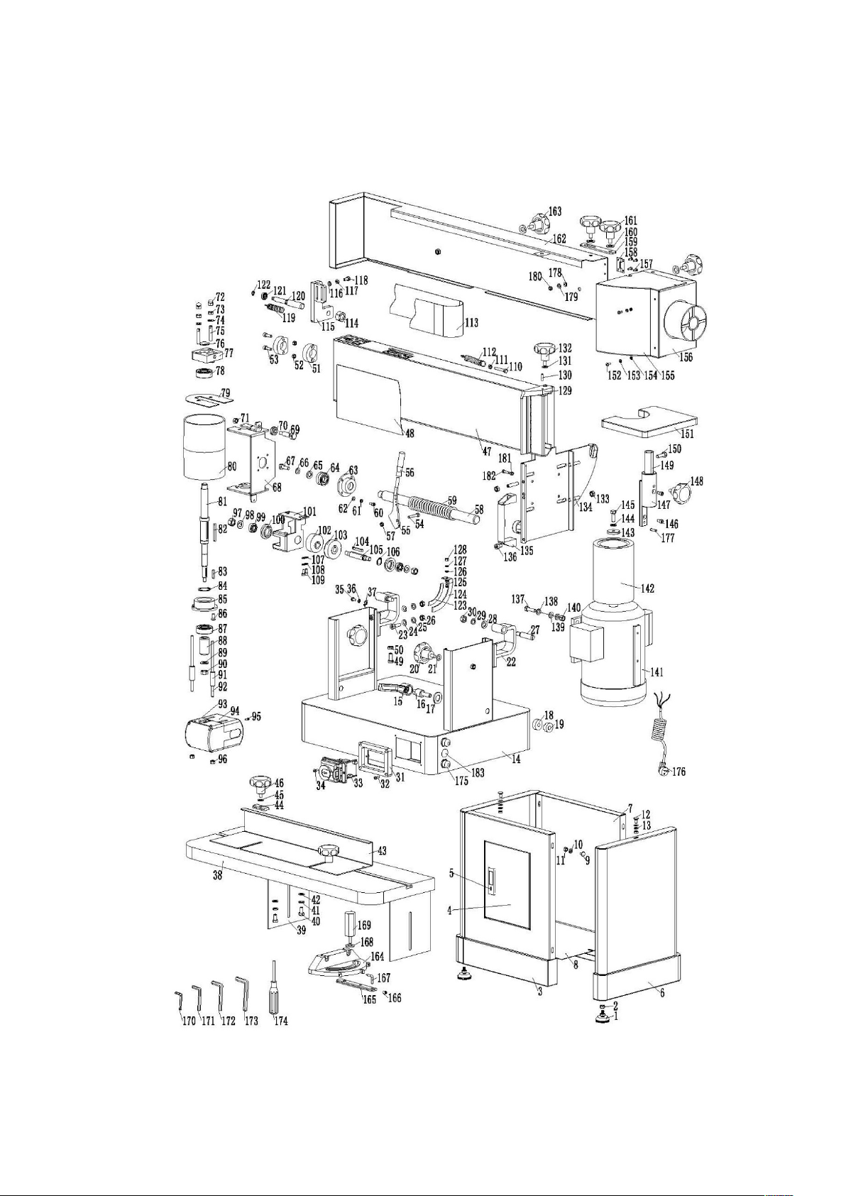
7. Diagram and part list
7.1 Exploded diagram 01
13
Page 15

7.2 Part list 01
!"#
$%&'() *+)"!
,-+.
!"#
$%&'() *+)"!
,-+.
/
*0$122
3%4+ +%!&)"! 50 (6
/
7
!8+92:
+%!& )"! 50(6 ;0! $4%
/
<
=(" !+ *0!%4>? @$""(A
/2B4"'C5! 8+
/
1
$""(/29
+%!& )"! 30(
/
2
40+'; 50&&%63 4.
/2D&*()!E
/
:
&)$% *0!%4
7:F("8!$5; %0 $5&4 "++%$ 60';)!%5& ' (%?
1
B
(% 0( *0!%4
/:/4"'C ?0&;%(
1
9
&;%4=/:7
=40+ ?0&;%(
1
D
;%G '0*5&'( % ?
/F:<3%0( )!E5;"8& ) !E
/
/F
=4 0+ ?0&;%(
/7:13044 3%0()!E
7
//
!8+/7:2
=40+ ?0&;%(
/
/7
;%G '0*5&'( % ?
7::=40+ ?0&;%(
/
/<
4"'C ?0&;%(
7:B&"'C %+5;% 0 $ ' 0*5&'(%?
/
/1
30& %/:9
)$4%5$(8653 (0' C% +
/
/2
3)E5C!"3
/ :D
+(0' C50$H8 & +)! )E5&'(%?
/
/:
4"'C534"'C
/ BF
+(0' C50$H8 & +)! E5! 8+
/
/B
=4 0+ ?0&;%(
/ B/
!.4" !5)!&% (+ 4"'C5! 8 +
/
/9
!.4 "! ?0&;%(
/ B7
&*%' )045!8 +
7
/D
4"'C5! 8+
/ B<
!8+
7
7F
C!"3
7 B1
=40+ ?0&;%(
7
7/
=4 0+ ?0&;%(
7 B2
$"834% I&'(%? 3" 4+
7
77
0!E 4%5* 40+%
7 B:
$)&'5* 40+%
/
7<
("8!$5; %0$5&4"++%$ 60';)!%5& ' (%?
1 BB
+(0' C50$H8 & +)! E534"'C
/
71
=4 0+ ?0&;%(
1 B9
3044 3%0()!E
/
72
4"'C ?0&;%(
1 BD
E80( $
/
7:
!8+
1 9F
)$4%5$(86
/
7B
&'(%?
7 9/
$()J%5& ;0 =+
/
79
=4 0+ ?0&;%(
7 97
C%.
/
7D
4"'C ?0&;%(
79<C%.
/
<F
;%G5! 8+791
(%+0)!)!E5()!E
/
</
&?)+'; 3"G
/92$"?!53 %0()!E ;"8&)!E
/
<7
*0! ; %0$5&'( %?
19:*;5'"8 !+%(& 8!C5; %0$5& ' (%?
<
<<
%KL MNLO PQ5RS TUPV
/9B3044 3%0()!E
/
<1
+0**)!E5&'(%?
799?"(6
/
<2
*0! ; %0$5&'( %?
/9D=40+ ?0&;%(
/
<:
%G+ %(! 04 +""+;54"'C ?0& ;%(
/DF4"'C5! 8+
/
<B
*") !+%(/D/
'"486!
7
<9
+034%/D7
$"834% I;%0$ 4% 0$5&'(%?
7
<D
8* I$"?! +034% 6"8 !+5* 40+%
7D<$8&+5;""$53"G
/
1F
&"'C %+5;% 0 $ '0*5&'(%?
1D1$8&+5;""$5'" J %(
/
1/
=4 0+ ?0&;%(
1D2&"'C %+5;% 0 $ ' 0*5&'(%?
1
17
4"'C ?0&;%(
1D:4"'C5! 8+
7
1<
=%!'%/DB
4"'C5! 8+
7
11
E8)$%534"'C
7D9=40+ ?0&;%(
7
12
=4 0+ ?0&;%(
7DD3044 3%0()!E
7
1:
C!"37/FF
3%0( )!E5;"8& ) !E
7
1B
*4 0+%!//F/
E%0 (5;"8&)!E
/
19
E( 0*;) +% *0$
/
/F7
'06
/
1D
&"'C %+5;% 0 $ '0*5&'(%?
/
/F<
?"(65E %0(
/
2F
!8+//F1
C%.
/
2/
()!E7/F2
?"(65E %0(5& ;0=+
/
27
4"'C5! 8+1/F:
(%+0)!)!E5()!E
/
2<
("8!$5; %0$5&4"++%$ 60';)!%5& ' (%?
1
/FB
=40+ ?0&;%(
1
21
&"'C %+5;% 0 $ '0*5&'(%?
/
/F9
4"'C ?0&;%(
1
14
Page 16

!"#
$%&'() * +)"!
,-+.
!"#
$%&'() *+)"!
,-+.
/01
("2!$34 %5$3& 6 " + +%$ 75' 4)!%3& '(%8
9
/9:
&2**" ( +)!;3& %5+
/
//0
&*()!;3<" 6+
/
/9=
>!"<
/
///
!2+/=/91
&2**" ( +)!;3( "$
/
//?
&*()!;//@0
&"'> % +34% 5$ '5*3&'(%8
/
//A
&5!$ )!;3<% 6+
/
/@/
%B+ %!&)"! +5<6%
/
//9
!2+//@?
*4)66)*&3&'(% 8
A
//@
<(5' >% +//@A
85&4%(
A
//C
D65+ 85&4%(
9
/@9
!2+
A
//:
6"'> 85&4%(
9
/@@
$2&+3*" (+
/
//=
&"'> %+34 % 5$ ' 5*3&'(%8
9
/@C
$(273; 25($
/
//1
&*()!;//@:
'6)!'43<" 6+
=
/?0
6%5$ 3&'(%8
/
/@=
4)!;%3< (5 '>% +
?
/?/
<566 <%5 ()!;
/
/@1
'"!!% ' +)"!3* 65+%
/
/??
(%+5) !)!;3()!;
/
/C0
D6 5+ 85&4%(
9
/?A
+)6+35! ;6%3& ' 56 % 6 5<%6
/
/C/
>"!<
?
/?9
+)6+ &' 56%
/ /C? &5! $)!;3<% 6+ ' "E%(
/
/?@
*5! 4 %5$ &'( %8
/ /CA >"!<
?
/?C
D65+ 85&4%(
? /C9 7)+ %( ;52;% <" $.
/
/?:
6"'> 85&4%(
/ /C@ ;2)$% < 5(
/
/?=
!2+
/ /CC &"'> % +34% 5$ '5*3&'(%8
/
/?1
<(5' >% +
/ /C: *") !+%(
/
/A0
*)!
/ /C= D6 5+ 85&4%(
/
/A/
D65+ 85&4%(
/ /C1 >!"<
/
/A?
>!"<
/ /:0 )!!%(34% B 5;" ! &*5!!%( A
/
/AA
!2+
A /:/ )!!%(34% B 5;" !3& *5!!%( 9
/
/A9
*5! 4 %5$3&'( %8
A /:? )!!%(34% B 5;" !3& *5!!%( @
/
/A@
45!$ 6%//:A
)!!%(34% B 5;" !3& *5!!%( C
/
/AC
("2!$34 %5$3& 6 " + +%$ 75' 4)!%3& '(%8
?
/:9
*4)66)*&3&'(% 8$()E%(
/
/A:
&"'> %+34 % 5$ ' 5*3&'(%8
9
/:@
&+( 5)!3(%6)%D
A
/A=
D65+ 85&4%(
=
/:C
*62;
/
/A1
6"'> 85&4%(
9
/::
&"'> % +34%B34 %5$3<" 6+37 =B/?
/
/90
!2+9/:=
D6 5+ 85&4%(3C
9
/9/
7"+"(//:1
&*()!; 85&4% (3C
9
/9?
$()E%3$(27
/
/=0
4%B3! 2 +37C
9
/9A
85&4%(//=/
4%B3! 2 +37C
9
/99
6"'> 85&4%(
/
/=?
4%B34 % 5$3&'( %837CB/C
9
/9@
&"'> %+34 % 5$ ' 5*3&'(%8
/
/=A
*6 5&+)'3)!&% (+
/
/9C
("2!$34 %5$3& 6 " + +%$ 75' 4)!%3& '(%8
?
15
Page 17
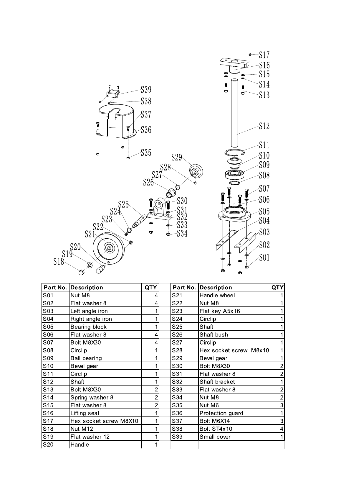
7.3 Exploded diagram and part list for table lifting handwheel assembly
16
Page 18
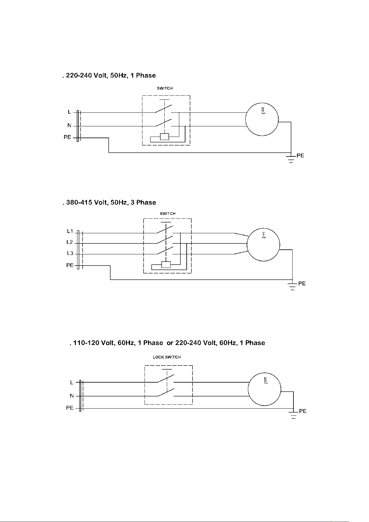
7.4 Wiring diagram
17
 Loading...