

Page 1

AP200SM
Spindle Moulder
Code 107703
Original Instructions
AT:05/12/2023
BOOK VERSION: 7
Page 2

INDEX OF CONTENTS
What’s Included 03-04
Optional Accessories 05
General Instructions for 230V Machines 06
Specific Safety Precautions 06-07
Specification 07
Assembly 08-09-10-11-12-13-14
Illustration & Parts Description 15-16-17-18-19-20
Positioning the Machine 21
Setting the Fence 21-23
Changing the Cutter Block 23-24
Changing the Spindle Speed 24-25
Operating Instructions 26-27
Optional Accessories 27-28
Routine Maintenance 29
Trouble Shooting Chart 28
Wiring Diagram 30
Exploded Diagrams/List 31-32-33-34-35-36-37-38-39-40
Declaration of Conformity 41-42
The symbols below advise the correct safety procedures when using this machine.
Fully read manual
and safety instructions
before use
Ear protection
should be worn
Eye protection
should be worn
2
Dust mask
should be worn
HAZARD
Page 3

WHAT’S INCLUDED
Quantity Item Part Model Number
MX5110A
1 No AP200SM Spindle Moulder AA
1 No Sliding Table Operating Handle AA1
Support Table Assembly AC
1 No Support Table AC1
2 No Lift & Shift Handles with Washers (M8 Thread) AC2
1 No Pre-drilled Steel Plate AC3
Spindle Guard Assembly AD
1 No Spindle Guard with Adjustable Fence AD1
2 No Lift & Shift Handles with Washers M8 x 140mm AD2
1 No Guide Assembly Mounting Bracket AD3
1 No Fence Top & Side Guards AD4
Guide Assembly AE
1 No Guide Arm & Guide Arm Clamping Plate AE1
1 No Guide Assembly AE2
1 No Anti-Kickback Assembly AE3
Mitre Fence Work Clamp Assembly AF
1 No 10mm Allen Key and 4mm Double Ended Allen Key
Spindle Preset Stop Pin Assembly
1 No Spindle Preset Stop Pin 90˚ to -5˚ AG
1 No Instruction Manual
OPTIONAL ACCESSORIES
Quantity Item Part
Extension Table Assembly AB Code: 950505
1 No Extension Table AB1
1 No Extension Table Fence (Adjustable) AB2
2 No Lift & Shift Handles with Washers AB3
1 No Pre-drilled Steel/Pin Plate AB4
2 No Caphead Screws and Washers AB5
1 No Pivot Arm with Four Bolts & Washers AB6
1 No Extension Table Support Rod AB7
1 No Co-Matic AF32 Junior Power Feed Code: 340195
1 No Tension Plate for AT200SM Spindle moulder Code: 950506
3
Page 4
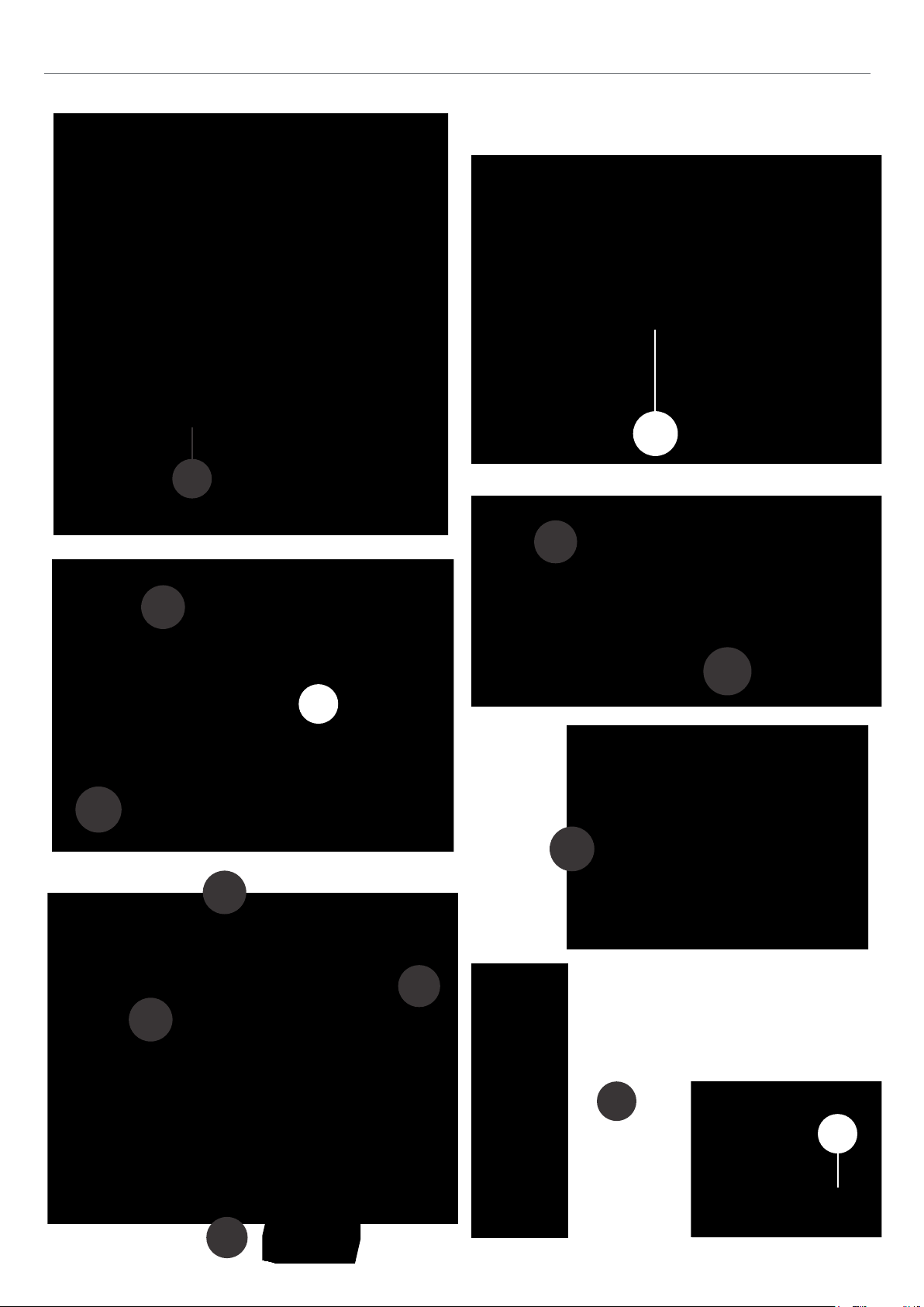
WHAT’S INCLUDED
WHAT’S INCLUDED
OPTIONAL ACCESSORIES
5
Code: 340195 Code: 950506
AB4
AB6
AB2
AB7
AB3
AB1
AB5
AA
AA1
AD1
AC3
AC1
AC2
AD4
AD3
AE2
AE3
AD2
AE1
AF
AG
Page 5

OPTIONAL ACCESSORIES
OPTIONAL ACCESSORIES
5
AB7
AB5
AB4
AB6
AB2
AB3
AB1
Code: 340195 Code: 950506
Page 6

GENERAL INSTRUCTIONS FOR 230V MACHINES
The following will enable you to observe good working
practices, keep yourself and fellow workers safe and maintain
your tools and equipment in good working order.
WARNING!! KEEP TOOLS AND EQUIPMENT
OUT OF REACH OF YOUNG CHILDREN
KEEP WORK AREA AS UNCLUTTERED AS IS
PRACTICAL. UNDER NO CIRCUMSTANCES SHOULD
CHILDREN BE ALLOWED IN WORK AREAS.
Mains Powered Tools
• Tools are supplied with an attached 16 Amp plug.
• Inspect the cable and plug to ensuree that neither are
damaged. Repair if necessary by a suitably qualified person.
• Do not use when or where it is liable to get wet.
Workplace
• Do not use 230V a.c. powered tools anywhere
within a site area that is flooded.
• Keep machine clean.
• Leave machine unplugged until work is about to commence.
• Always disconnect by pulling on the plug body and not the
cable.
• Carry out a final check e.g. check the cutting tool
is securely tightened in the machine and
speed and function set.
the correct
• Ensure you are comfortable before you start work,
balanced, not reaching etc.
•
Wear appropriate safety clothing, goggles, gloves,
masks etc. Wear ear defenders at all times.
• If you have long hair wear a hair net or helmet to prevent it
being caught up in the rotating parts of the machine.
• Consideration should be given to the removal of rings and
wristwatches.
• Consideration should also be given to non-slip footwear etc.
• If another person is to use the machine, ensure they are
suitably qualified to use it.
• Do not use the machine if you are tired or distracted
• Do not use this machine within the designated safety areas
of flammable liquid stores or in areas where there may be
volatile gases.
• Check cutters are correct type and size, are undamaged
and are kept clean and sharp, this will maintain their
operating performance and lessen the loading on the
machine.
• OBSERVE…. make sure you know what is happening
around you and USE YOUR COMMON SENSE.
SPECIFIC SAFETY PRECAUTIONS
Authorised Use
This machine is designed for shaping wood and wood derived
materials.
• Machining of other materials is not permitted and may be
carried out in specific cases only after consulting with the
manufacturer.
• The proper use also includes compliance with the operating
and maintenance instructions given in this manual
• The machine must be operated only by persons familiar with
its operation and maintenance and who are familiar with its
hazards.
• The required minimum age must be observed.
• The machine must only be used in a technically perfect
condition.
• When working on the machine, all safety mechanisms and
covers must be in operation.
6
Page 7

SPECIFIC SAFETY PRECAUTIONS
• In addition to the safety requirements contained in these
operating instructions and your country’s applicable regulations, you should observe the generally recognized technical
rules concerning the operation of woodworking machines.
• Any other use exceeds authorisation.
• In the event of unauthorised use of the machine, the
manufacturer renounces all liability and the responsibility is
transferred exclusively to the operator.
General Safety Notes
• Woodworking machines can be dangerous if not used properly.
Therefore the appropriate general technical rules as well as the
following notes must be observed.
• Read and understand the entire instruction manual before
attempting assembly or operation.
• Keep these operating instructions close by the machine,
protected from dirt and humidity, and pass them over to the
new owner if you part with the tool.
appliances before you start the machine.
• Remove all loose clothing and enclose long hair.
• Before operating the machine, remove tie, rings, watches,
other jewellery, and roll up sleeves above elbows.
• Wear safety shoes; never wear leisure shoes or sandals.
• Always wear the approved working outfit.
• Do not wear gloves while operating the machine.
• For the safe handling of cutting tools wear work gloves.
• Control the stopping time of the machine, it may not
exceed 10 seconds.
• Remove cut and jammed work pieces only when the
machine is at a complete standstill and motor is turned off.
• Install the machine so that there is sufficient space for safe
operation and work piece handling.
• No changes to the machine may be made.
• Daily inspect the function and existence of the safety
• Keep work area well lit.
SPECIFICATION
Code 107703
Model AP200SM
Rating Trade/Professional
Power 2.8 kW 230V 1ph
Spindle Travel 100 mm
Spindle Diameter 30 mm
Spindle Speed 1,800, 3,000, 6,000 & 9,000 rpm
Max Spindle Projection above Table 100 mm
Max Tooling Diameter Above Table 200 mm
Max Tooling Diameter Below Table 180 mm
Table Height 900 mm
Table Size 1,000 mm x 360 mm
Min Extraction Airflow Required 1,000 m³/hr
Noise Level dB(A) 77.2dB(A)
Dust Extraction Outlet 2 x 100 mm
Overall L x W x H 1,010 mm x 690 mm x 900 mm
Weight 218 kg
7
Page 8
ASSEMBLY
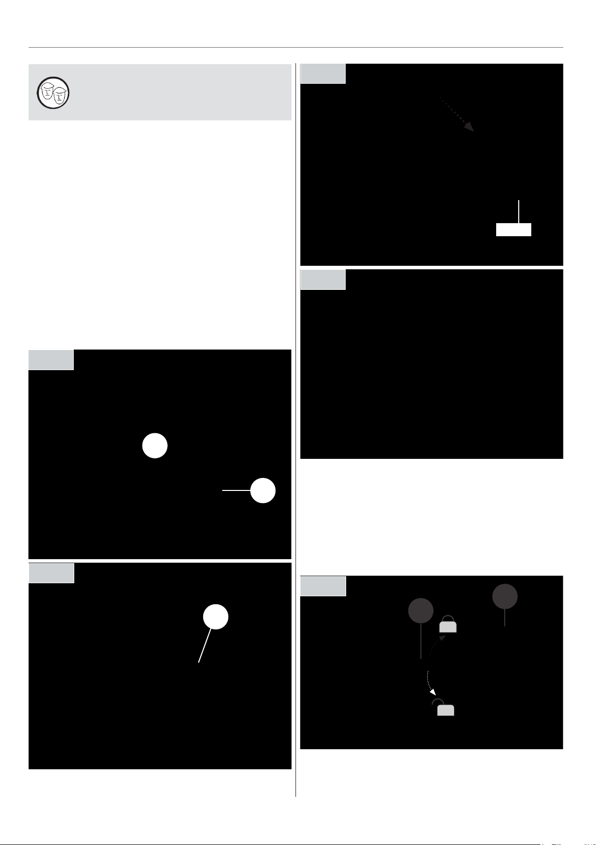
PLEASE NOTE: FOR YOUR OWN SAFETY IT
IS REQUIRED THAT TWO PEOPLE ASSEMBLE
THIS MACHINE!
Unpack all the boxes and check all the components against
the “What’s in the Boxes’ List. If any parts or components are
missing, please contact our customer services department
using the procedures and telephone numbers liste on our
website, and you will be dealt with quickly and efficiently.
Having unpacked the boxes, (please dispose of any unwanted
packaging responsibly), put the parts and components
whereby they are readily to hand. Break down the main box
by knocking the sides away (be careful of exposed nails etc.),
but leave the machine sitting on its pallet. Remove the
protective grease film that is coating all the unpainted parts
of the machine.
Support Table Assembly
Fig 01
Fig 03
‘T’ Slot
Fig 04
Fig 02
C1
C2
C3
Spindle Guard Assembly
1. Raise the spindle to its maximum height by unlocking the
spindle moulder’s rise/fall locking handle (A) and turning the
operating wheel (B) clockwise. Re-lock the spindle in place, see
fig 05.
Fig 05
B
A
8
Page 9

ASSEMBLY
Fence Guards
The spindle moulder comes with new guarding and
guide arm assembly. Please follow the instructions
below to install.
Top Guard
D4
Side Guards
Fig 6
D1
D2
Lift & shift handles
Fig 8
Fig 9
Fig 10
D4
Shaft
Fig 7
Fence carriage
Countersink Hex screw
1. Remove the both fence’s and place safely aside,
see fig 01. Using a Hex key remove the countersink
screws holding the fence carriages and slide the
carriages off the shafts, see fig 07.
2. Locate the left and right side angle guards (B),
line up the centre holes in the guards and slide
them over the shafts, see fig 08.
Fig 11
Fig 12
3. Replace both carriages and secure in place,
see fig 09-10-11.
4. Slide the adjustable aluminium fences back onto
the carriages and nip-up the locking knobs, see fig 12.
9
Continues Over...
Page 10
ASSEMBLY
Guide & Anti-Kick Back Assembly
Guide
Assembly
Mounting
Bracket
Anti-Kickback
Assembly
Guide Arm
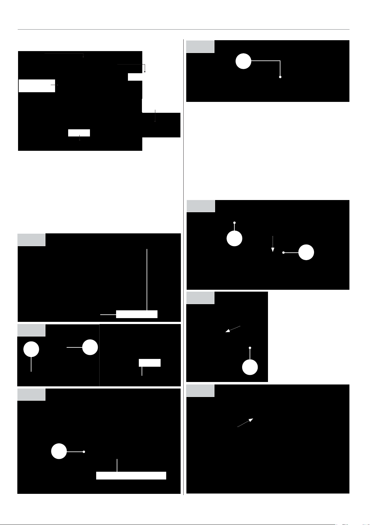
1. Lower the spindle guard assembly (D1) down onto the table,
line up the two threaded holes on either side of the spindle
with the slots in the guard secured in place with the lift & shift
handles (D2), see fig 13-14-15.
2. Secure the guide mounting bracket (D3) on top of the spindle
guard assembly (D1) using two cap head bolts & washers, see
fig 09. NOTE: Only use the two rear holes on the mounting
bracket in preuration for the next step.
Guide Assembly
Guide Arm
Clamping Plate
Fig 16
D4
3. Locate the top guard (D4) and two cap head bolts/washers.
Lower the guard down on top of the adjustable fence.
Line-up holes in the top guard with the holes on the guide
mounting bracket (D3) and secure in place with the cap head
bolts/washers, see fig 16.
4. Put together the guide assembly as shown in figures
17-18-19.
5. Slide the guide assembly arm through the mounting
bracket and nip-up the clamping handle.
Fig 17
Fig 13
Fig 14
D1
Fig 15
D2
Threaded holes
‘T’ Slot
Fig 18
Fig 19
E1
E2
E3
D3
Guide arm
clamping plate
D3
Cap head bolts & washer
10
Page 11

ASSEMBLY
Sliding Table Operating Handle
Fig 20
‘T’ Slot’
Lock
A1
Mitre Fence Work Clamp Assembly
Fig 21
Optional Extension Table Assembly (Code 950505)
1. Line up the pivot arm mounting bracket (B6) with the four
threaded holes to the side of the spindle moulder (A) and
secure in place with four bolts and washers provided, see fig
24-25-26-27.
Fig 24
A
Threaded holes
Fig 22
‘T’ Slot’
Fig 25 Fig 26
F
Fig 27
B6
Fig 23
Locking knob
Angle lock
11
Page 12
ASSEMBLY
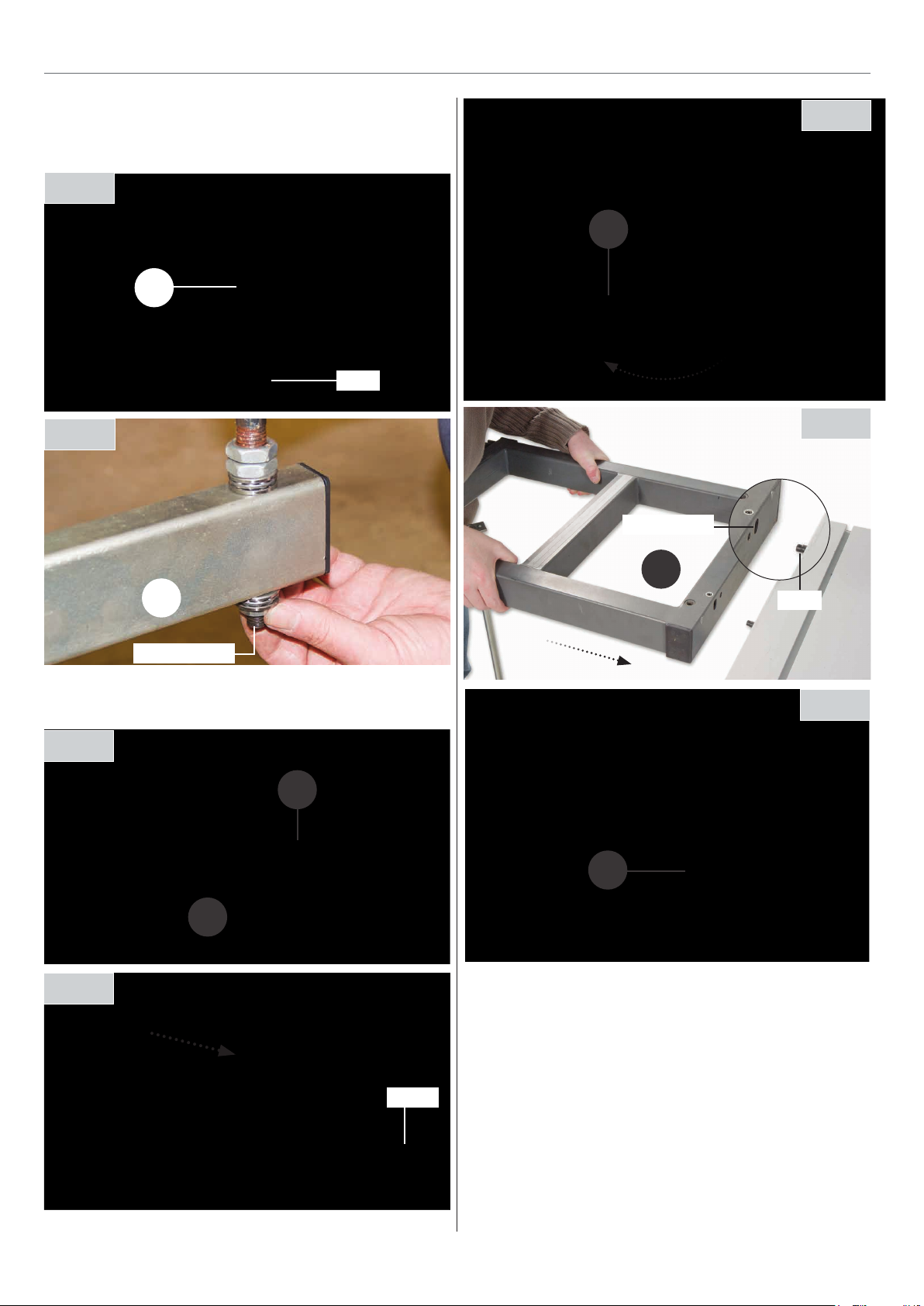
2. Pull out the extension table support arm (B6) and introduce
the support rod (B7) through the hole on the support arm (B6)
and secure in place using the nuts and washers, see fig 28-29.
Fig 28
B7
Hole
Fig 29
Fig 32
B6
Fig 33
Machined slot
B6
Nuts & washers
3. Slide the steel/pin plate (B4) into the machined ‘T’ slot to the
left side of the sliding table, see fig 30-31.
Fig 30
B4
B5
Fig 31
B1
Pin
Fig 34
B3
4. Pull out the table support arm (B6), insert the machined slots
in the extension table (B1) over the pins (B4). Locate the two
lift & shift handles (B3), insert them through the holes in the
table (B1) into the threaded holes in the steel plate (B4), see fig
32-33-34.
‘T’ Slot’
12
Page 13
ASSEMBLY
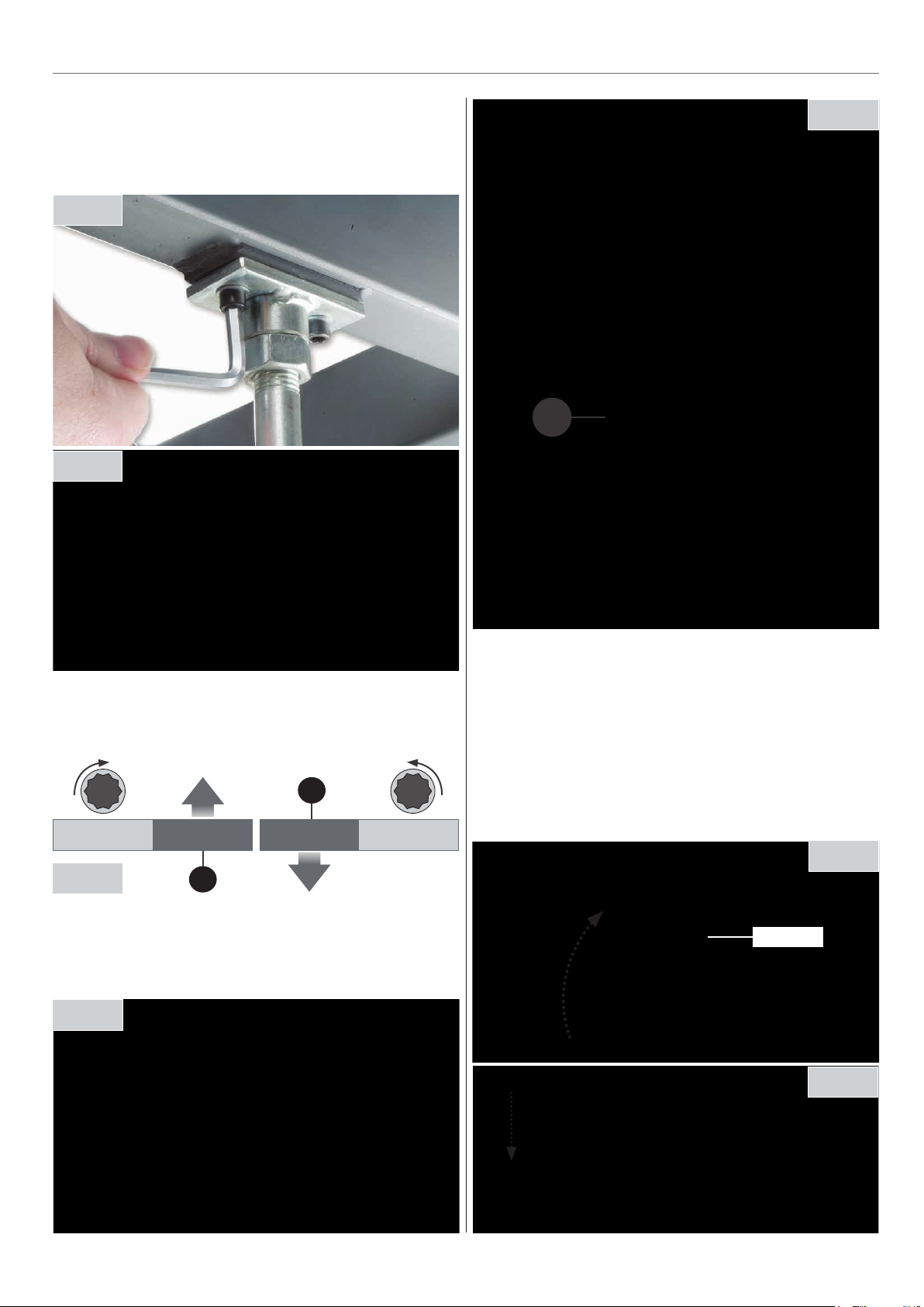
5. Locate the two cap head screws/washers (B5), line up the
table support rod bracket (B7) with the two pre-drilled holes
beneath the extension table (B1) and secure in place with the
cap head screws (B5), see fig 35.
Fig 35
Fig 36
Fig 39
B7
6. Place a straight edge across both tables and using a Hex key
adjust the two grub screws on the extension table (B1) until
both tables are level, see fig 36-37.
B1
Fig 37
7. Place a level on the extension table (B1) and using two
spanners adjust nuts on the support rod (B7) until the
extension table is level, see fig 38-39.
B1
Fig 38
8. Lift up the left 90˚ stop, see fig 40 lower the fence (B2) down
onto the extension table (B1) making sure the ‘PIN’ beneath the
fence engages into the hole on top of the extension table (B1).
Push the fence up against the 90˚ stop, see fig 41-42.
9. Slide the fence clamping bracket (B2) over the tables column
(B1) and tighten the butterfly nut. Lastly turn the fence locking
handle to secure it in position, see fig 43-44.
Fig 40
90˚ Stop
Fig 41
13
Continues Over...
Page 14
ASSEMBLY
Pin
Fig 42
Fig 43
Step 3 Fig 47
Hole
Fig 44
Step 4 Fig 48
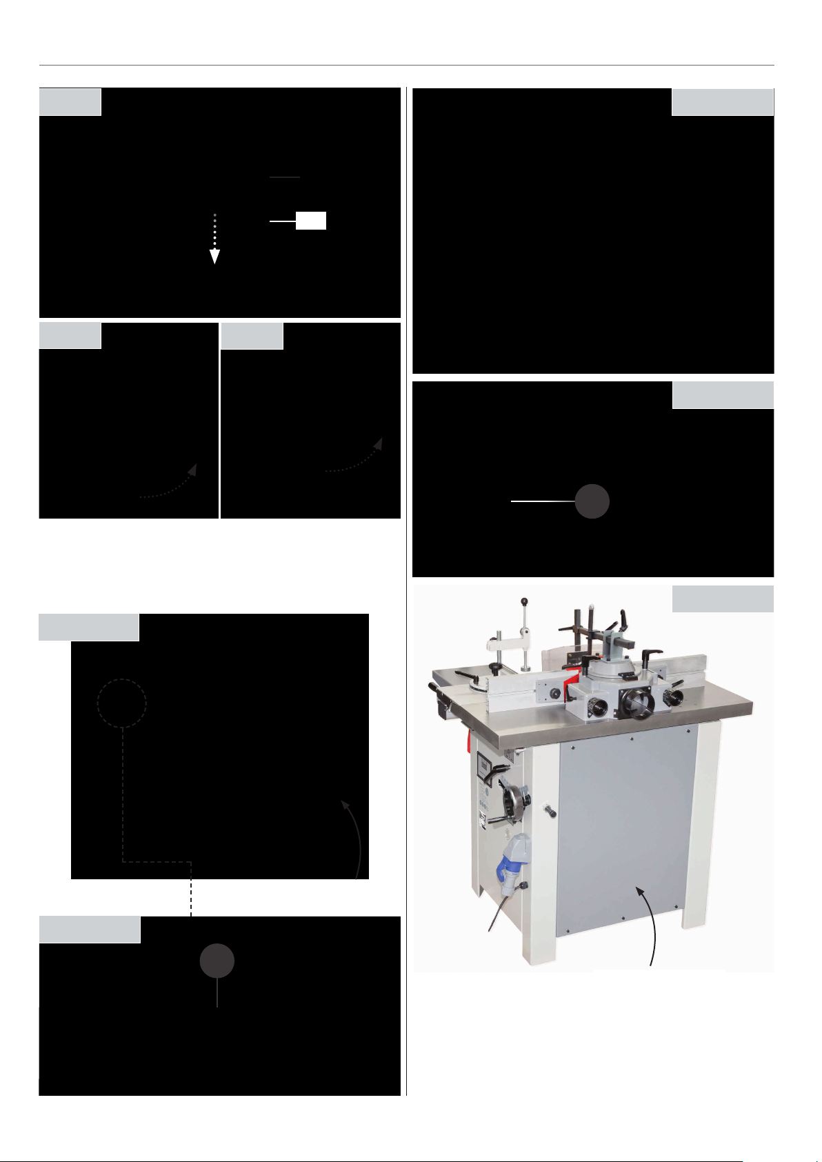
Spindle Preset Stop Pin 90˚ to -5˚
Follow the instructions below to assemble the spindle stop
assembly (G).
Step 1 Fig 45
Access panel
G
Step 5 Fig 49
Step 2 Fig 46
G
Replace access panel
14
Page 15
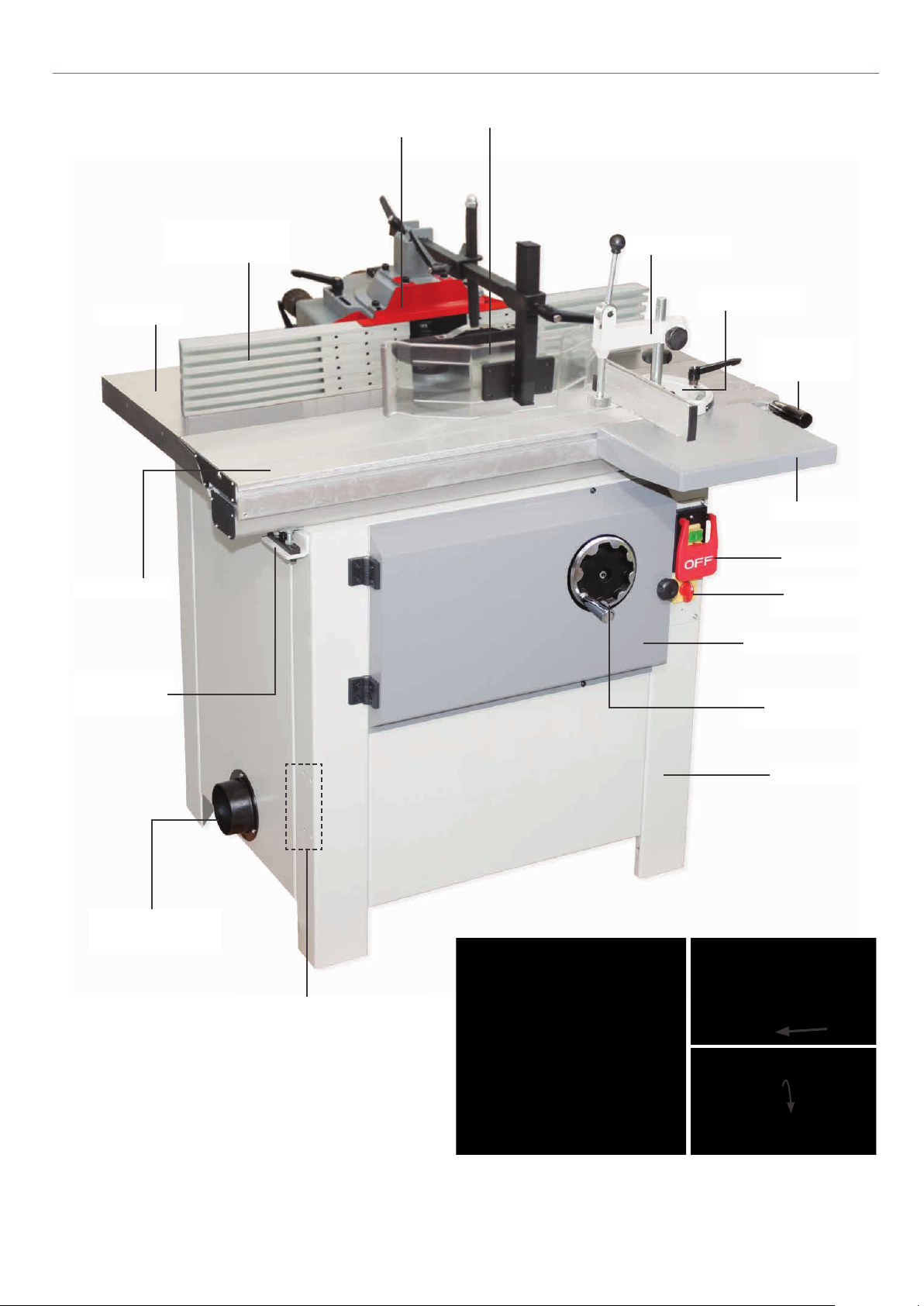
ILLUSTRATION & PARTS DESCRIPTION
Work table
Fence with
adjustable fingers
Fence top guard
Anti-kickback assembly
Work clamp
Mitre fence
Sliding table
handle
Table support
NVR switch
Sliding table
Sliding table
height assembly
100mm Dust
extraction outlet
Reversing
selector switch
Motor access door
Spindle tilt
operating handle
Spindle body
Pivot arm mounting holes for
extension table assembly
15
Sliding table locking knob
Pull out the knob and twist
Page 16
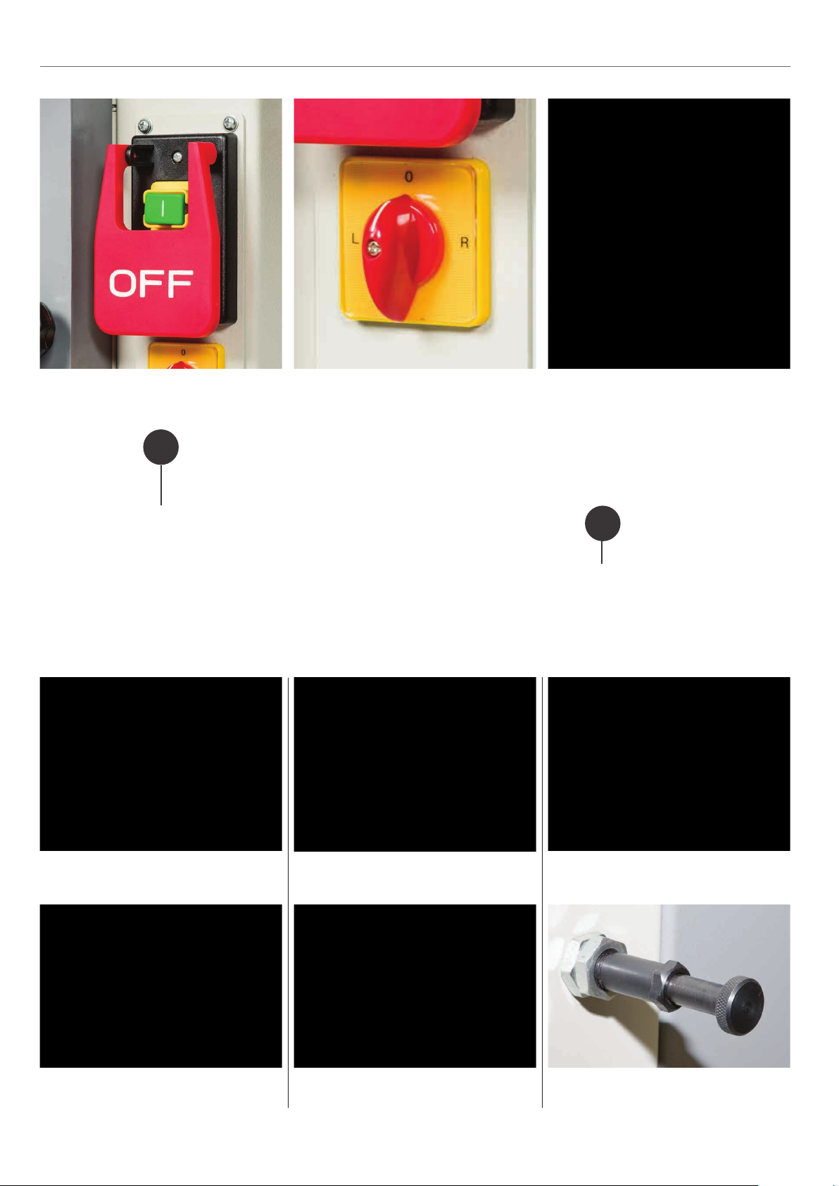
ILLUSTRATION & PARTS DESCRIPTION
NVR Switch assembly with a slap down
emergency stop lever
A
Fully adjustable fences (A) with adjustable fingers (B)
Reversing selector switch Mitre fence work clamp assembly
B
Spindle at -45˚ degrees
Spindle tilt operating wheel Spindle preset stop pin
Spindle at 90˚ degrees
set at 90˚ degrees
16
Spindle at +05˚ degrees
Spindle preset stop pin
set at +05˚ degrees
Page 17
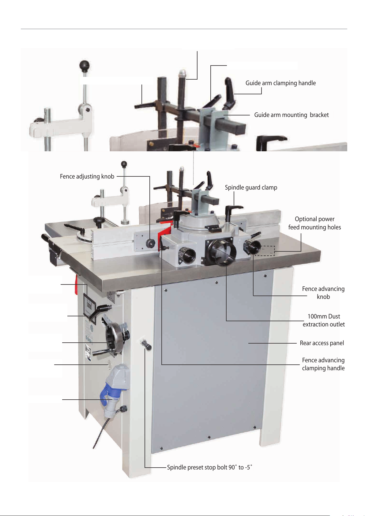
Fence advancing
knob
Guide arm clamping handle
Guide arm mounting bracket
Fence advancing
clamping handle
Anti-kickback height clamp
Optional power
feed mounting holes
Spindle guard clamp
Fence adjusting knob
100mm Dust
extraction outlet
Rear access panel
Spindle preset stop bolt 90˚ to -5˚
ILLUSTRATION & PARTS DESCRIPTION
Guide roller clamp
Feed guide height clamp
Spindle speed
digital display
Spindle tilt
clamping handle
Spindle height
control wheel
Spindle
height scale
16 AMP socket
17
Page 18
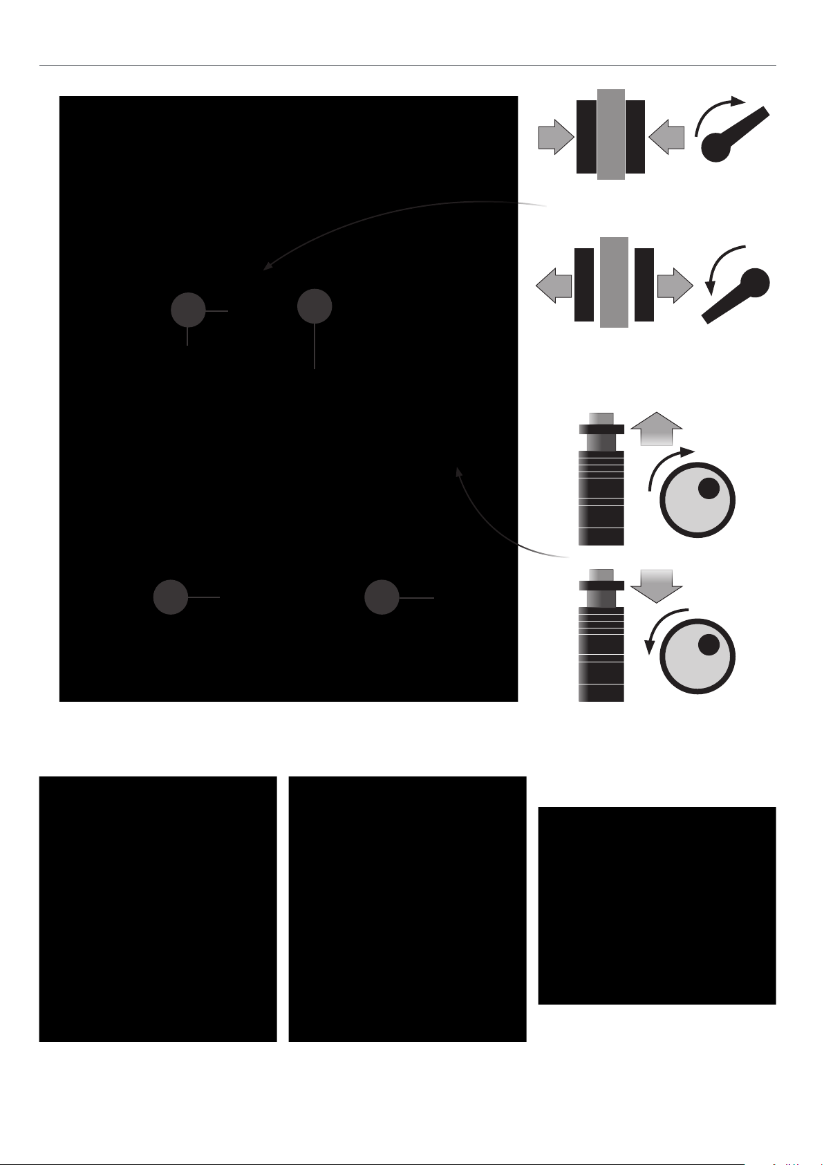
ILLUSTRATION & PARTS DESCRIPTION
Lock
A
B
C D
Un-Lock
Spindle tilt clamp illustration
Spindle tilt locking handle and scale (A), Spindle rise & fall locking handle (B),
Spindle height scale (C), 16 AMP socket for optional AF32 power feed assembly (D)
Spindle height scale Spindle tilt scale
18
Spindle rise and fall illustration
Spindle speed digital display
Page 19
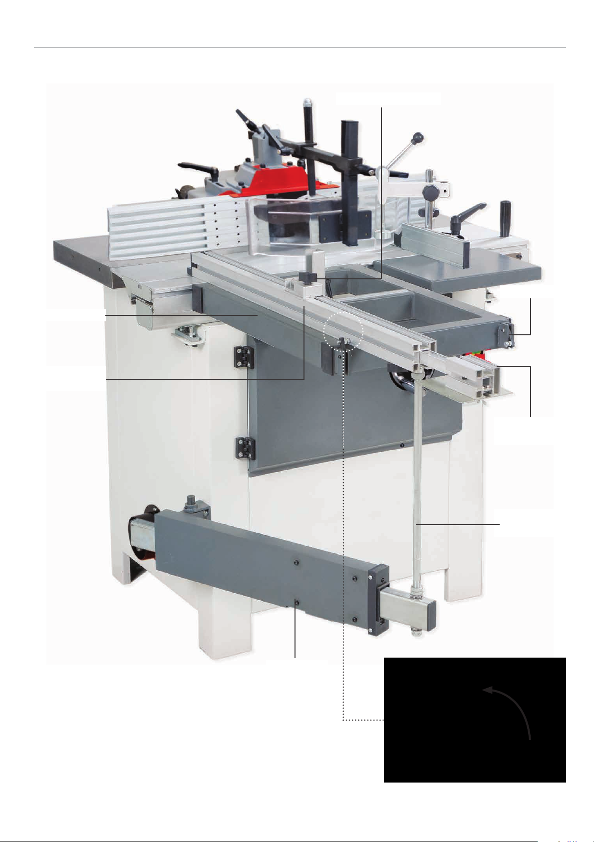
Spindle Moulder with Extension Table Fitted
Extension table
ILLUSTRATION & PARTS DESCRIPTION
Distance stop assembly
Fence 90˚ stop
Extension table
fence
Telescopic
fence extension
Extension table
support rod
Pivot arm
19
Extension table fence 90˚ stop
Page 20

ILLUSTRATION & PARTS DESCRIPTION
45˚
Table fence set to 45˚ Extension table angle scale
A
Distance stop assembly
magnifying glass (A), Clamp (B)
A
Telescopic extension assembly
B
C
Main table height adjusting nuts (A) Sliding table height adjusting nuts (B)
Table clearance adjusting nut (C)
20
Page 21
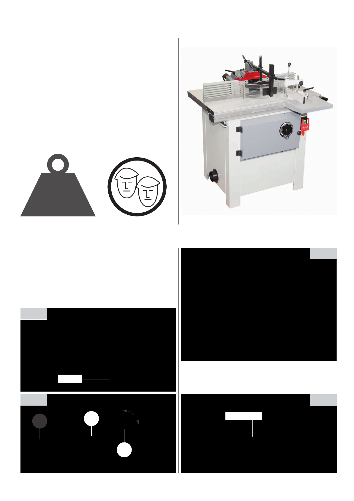
Ascertain the orientation of the machine and move it to its
desired position in the workshop. Ensure that the machine is
positioned to allow sufficient clearance all round to cater for
the maximum length of timber you wish to machine.
The machine should be positioned on a flat level surface.
Manoeuvre the machine to the chosen location, then carefully
lower the machine down.
SAFETY WARNING!
The WS1000TA Spindle Moulder is a heavy piece of
equipment. You are advised to seek help or the use of some
form of lifting device, (hoist, engine crane etc.,) before you
attempt to lift or move this machine.
POSITIONING THE MACHINE
218kg
SETTING THE FENCE
The fence is a two piece adjusting system. Each fence is
independently adjustable to compensate for different
cutting thicknesses. Make sure the fence is square to the work
surface, place a 90° square up against the fence and check it is
perpendicular to the work surface. If adjustment is required
turn the fence adjusting knob (a) until it is correct, see fig
50-51-52.
Fig 50
Square
Fig 52
Place a straight edge up-against both fences, loosen the fence
advancing clamping handles (b) and turn the fence advancing
knobs (c) until both fences are aligned, see fig 53.
Fig 51
c
b
Fig 53
Straight edge
a
21
Page 22
SETTING THE FENCE
5mm
Fence
Fence
Cutter block
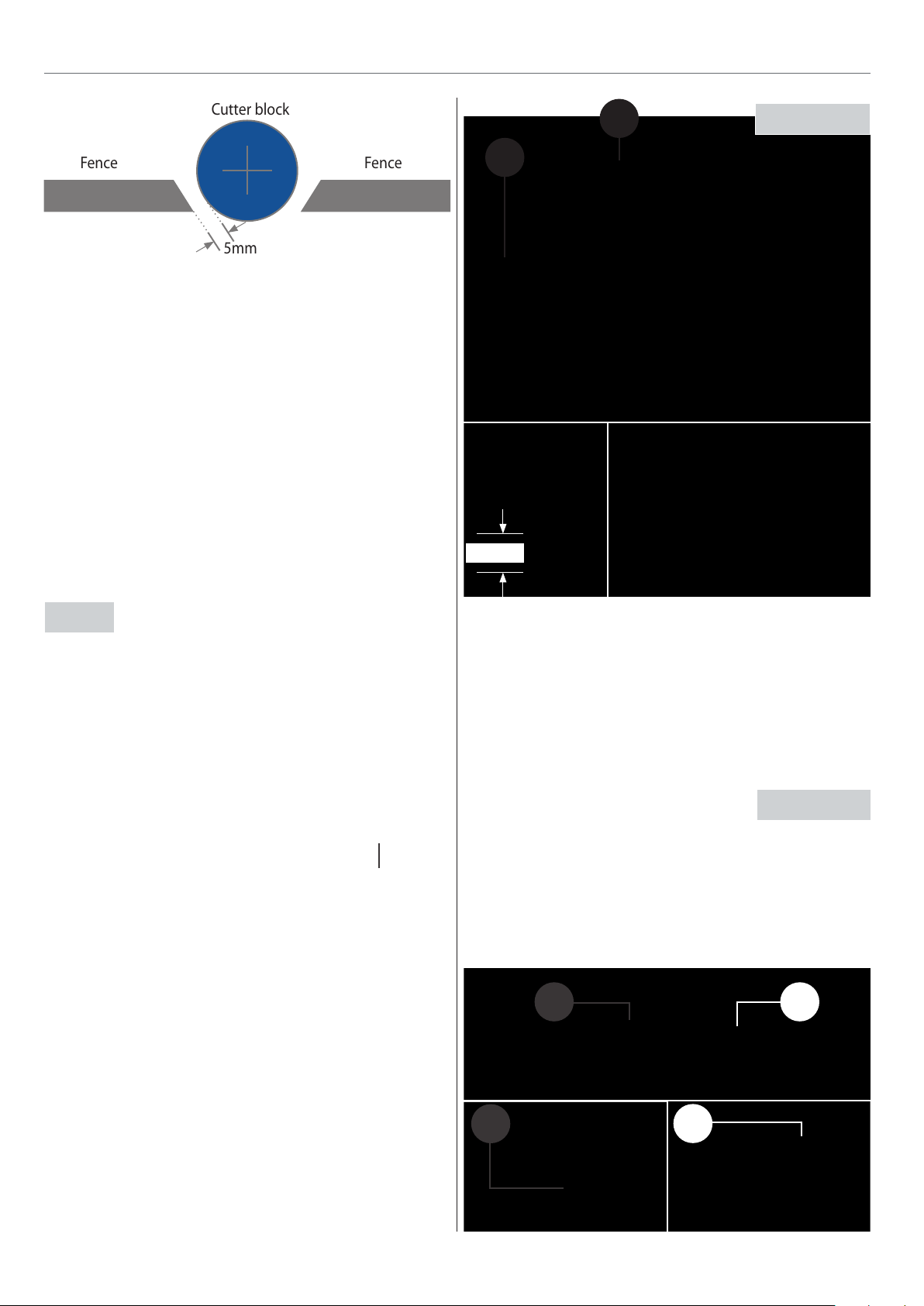
Adjust the position of the fence assembly to give both the
required cutter protrusion and adequate clearance between
the cutter and the fence. Close up the aluminium fences to
give approximately 5mm clearance around the cutter, see
diagram above.
NOTE: For improved safety the fence assembly has an integral
finger fence system designed to enclose the gap around the
cutting area. Set the cutter block & fence to the desired
position, release the 3 grub screws & slide each finger into
position leaving approximately 6-8mm gap around the cutter
block., see fig 53.
- Remember to remove all central grub screws that aren’t
locked in place.
b
5-10mm
a
Fig 55-56
Central grub
Fig 54
The fence is used to guide small work pieces through the cutter
without them being trapped between the fence and the cutter.
The dust extraction hose is connected to the aperture at the
rear of the fence assembly.
Before starting work, carefully check that the cutter can rotate
freely without fouling the inside of the guard and that the
guard is clamped firmly in place.
screw removed
Fingers
Grub screw
Levelling the Sliding Table
Note: The tables are preset at the factory but can be adjusted.
The sliding table should sit 0.5mm above and level with the
main saw table. Place a straight edge (e) across the joint of both
tables, if adjustment is required loosen the 3 nuts (c) beneath
the sliding table and adjust the two coach bolts (d) to obtain
thecorrect position, retighten the three nuts, see fig 57-58.
Fig 57-58
e
Work table
c
0.5mm
Sliding table
c
Adjusting the Feed Guide & Ant-Kickback Assembly
Loosen the feed guide clamp handle (a) and move the feed
guide to the centre of the work piece, retighten the handle.
Undo the anti-kickback clamp handle (b) and move the
assembly near the work piece, retighten the handle. Raise the
anti-kickback assembly so the steel plate is about 5-10mm
above the work table, see figs 55-56.
22
c
d
Page 23

SETTING THE FENCECHANGING THE CUTTER BLOCK
Sliding Table Clearance
Fig 59
Fig 60
a
Fig 61
Feeler gauge
D
E
C
Loosen the sliding table clamping nut (a). Slot the feeler gauge
down the gap between the two tables from one side and
adjust until the gap is set between (0.5 to 2mm), repeat the
procedure for the opposite side. Retighten the nuts (a) to
secure the table in position, see fig 59-60.
Changing the Cutter Block
Raise the spindle to the maximum height by unlocking the
rise/fall locking handle (A), turning the spindle moulder
rise/fall handle (B) clockwise then lock in place, see fig 60-61.
Using a 19mm spanner remove the bolt & clamping block (C),
spacing collar/s (D) and clamping washer (E) and place them
safely aside, remove the cutter block, see fig 62. Check the new
cutter block for damage,sharpness etc. Fit the new cutter block
on the arbor as low as possible, see fig 63-64. Watch the
direction of rotation (counter-clockwise) when mounting the
cutter. Replace the clamping washer (E), spacing collar/s (D),
clamping block (C) and bolt. Tighten securely.
Fig 60
B
A
Fig 62
19mm spanner
Fig 63
C
Cutter block
23
E
Continues Over...
D
Page 24
CHANGING THE CUTTER BLOCKCHANGING THE SPINDLE SPEED
IMPORTANT NOTES:
• There is a risk of personal injury by cuts from the
cutter knives. Wear suitable gloves when changing cutters.
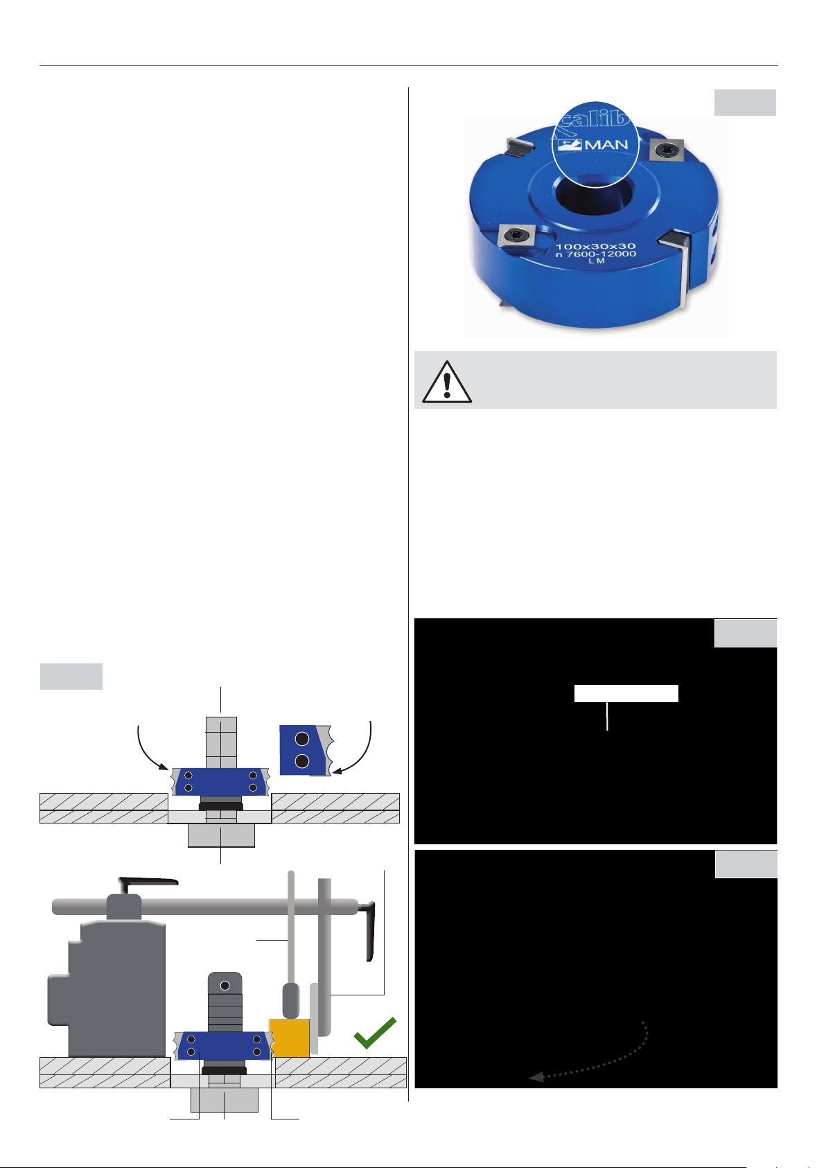
Only use tooling with manual feed cutter blocks marked
“MAN”, see fig 65.
• Clean all surfaces of cutters and spindle arbor before
remounting the cutter block.
• Unsuitable, incorrectly mounted, dull, cracked or bent cutter
knives can break or increase the risk of kickback considerably.
• The installation of sanding or polishing tools is not permissible.
• The cutter block must be positioned on the arbor as low as
possible, see diagrams below.
• Watch the direction of rotation (counter-clockwise) when
mounting the cutter.
• Fill the space between cutter and clamping washer with
spacing collars.
• Tighten the arbor cap head screw securely.
• Don’t use a wrench extension or a hammer to tighten the
cap head screw.
Fig 65
DISCONNECT THE MACHINE FROM THE
MAINS SUPPLY
Changing the Spindle Speed
Open the motor access door to the front of the machine, by
removing the two cap head screws, see figs 66-67 lower the
spindle to it’s lowest point, if not done so already. Locate the
10mm Hex key (F), loosen the cap head bolt (G) on top of the
motor, pull the motor tension lever (H) out, to allow the belt
to go slack and reposition the belt on the pulleys as required.
When you are happy, push back the tension lever H) and
tighten the cap head bolt (G) to keep the tension, see fig 68-69.
• Cover the clearance zone around the cutter with table
insert rings
The base of the lower
Fig 64
Cutter block
Feed Guide
blade tip should sit just
below the suface of the
table
Anti-kickback Plate
Fig 66
Cap head screw
Fig 67
Cutter Block
Blade
24
Page 25
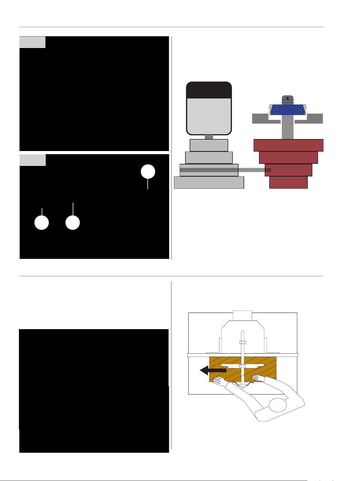
Fig 68
CHANGING THE SPINDLE SPEED
Spindle Chart
Spindle
Motor
1,800
Fig 69
F
GH
OPERATING INSTRUCTIONS
HSE (Health and Safety Executive)
To operate the machine correctly, it is recommended to read
the HSE (Health and Safety Executive) information working
sheet on the safe use of the Spindle Moulder.
3,000
6,000
9,000
RPM
Close the access door, raise the spindle, reconnect the
machine to the mains supply. Give the machine a ‘quick’
burst check (i.e. quick ON-OFF) to ensure everything is O.K.
If everything is satisfactory, continue to use the machine.
Correct Operating Position
Position yourself offset to the machine as shown.
Work Piece Handling
• Feed the work piece straight across the machine table, holding the fingers close together and guiding the work piece
with the palms of your hands.
25
Continues Over...
Page 26
OPERATING INSTRUCTIONS
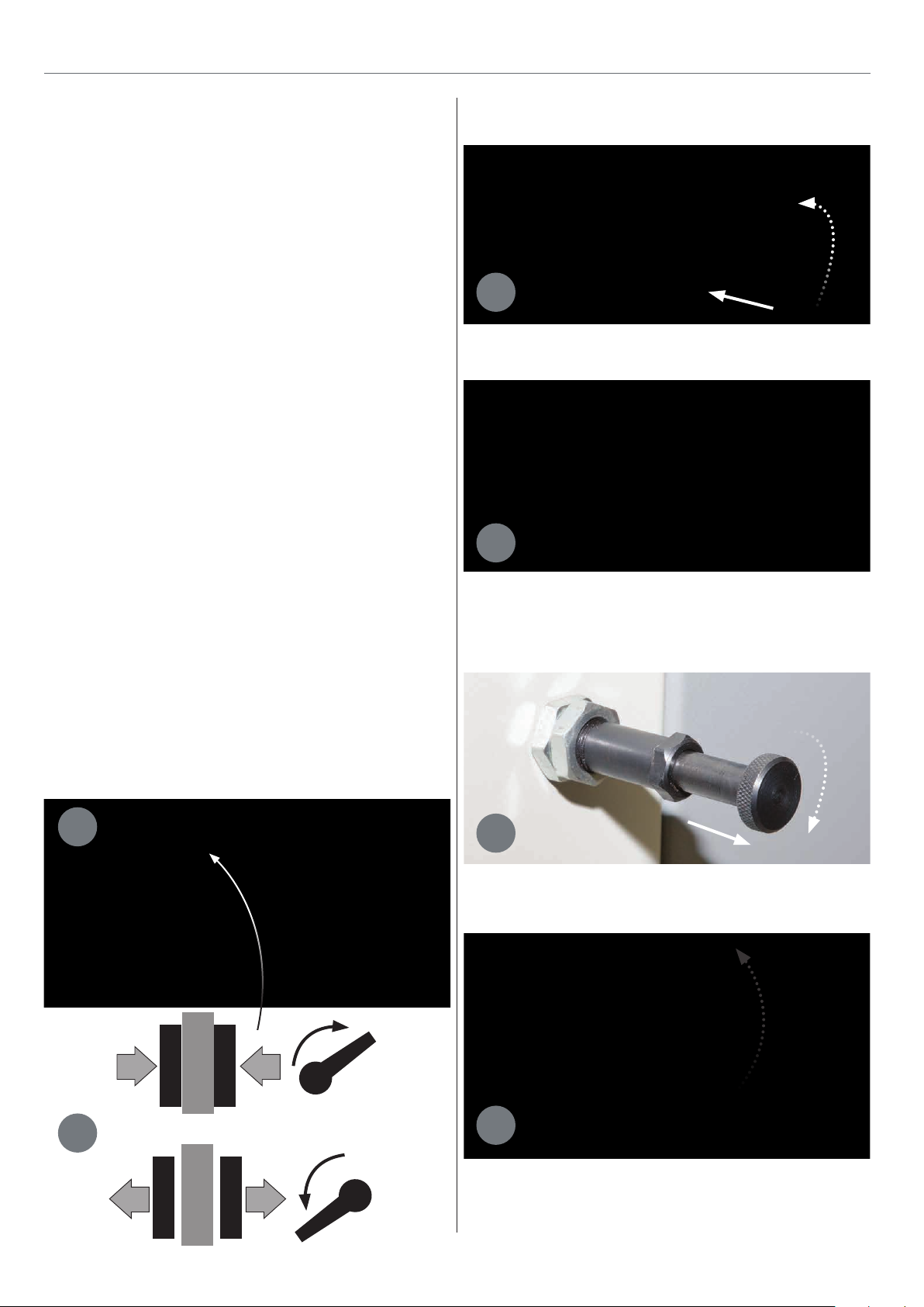
• Feed the work piece straight across the machine table, holding
the fingers close together and guiding the work piece with the
palms of your hands.
• Never put your hands under or behind the cutter guard.
• Always keep your hands well clear of the rotating cutter.
• Always feed the work piece against the cutter rotation as
shown by the arrow in illustration.
• Use a push stick when working the ends of narrow stock.
• Use a feeding aid if you are going to machine a work piece
shorter than 300mm.
• Always machine the work piece over its entire length.
Recess machining may only be carried out with the
aid of suitable longitudinal work piece stops.
• When working complex shapes, make jigs and guides to
guide the work piece properly and safely.
Setting Spindle at 90˚ (degrees)
1
Preset stop bolt set at 90˚ degrees
2
• Make trial cuts on a piece of scrap before working the actual
work piece.
• Support long work pieces with roller stands or table
extensions.
• Always work one work piece at a time.
Setting the Spindle Angles
1
Spindle at 90˚ degrees
Setting Spindle at -5˚ (degrees)
1
Preset stop bolt set at +05˚ degrees
2
Lock
Un-Lock
2
26
Page 27

3
+05˚
45˚
Spindle at +05˚ degrees
Setting Spindle at 45˚ (degrees)
OPERATING INSTRUCTIONS OPTIONAL ACCESSORIES
Fig 70
Tenon Plate Code: 950506
1
2
Spindle at 45˚ degrees
Optional Accessories
The spindle moulder can be fitted with the following optional
accessories:
This accessory is a simple alloy plate that lifts the work piece
above the table. This means that you can machine the top and
bottom surface of the work, such as when creating a tenon. It
can be mounted next to the mitre fence and clamp so as to
make the machining of end grain material as safe as possible.
Overall length 650mm x 120mm width, see fig 71.
• Special tenon plate to allow machining to the top
and bottom of the work piece
• Allows up to 200mm diameter tooling to be used
• Easy and safe to use, clamps next to the mitre fence
Fig 71
Extension Table Assembly Code: 950505
This accessory is a support table complete with a telescopic
support arm. It clamps to the sliding table to provide extra
support when machining panels or the ends of long
boards, see fig 70.
• Provides support for panels and long boards
• Easy to fit and can be removed for storage when not required
• Supplied with a long fence with a length stop
27
Continues Over...
Page 28
OPTIONAL ACCESSORIES
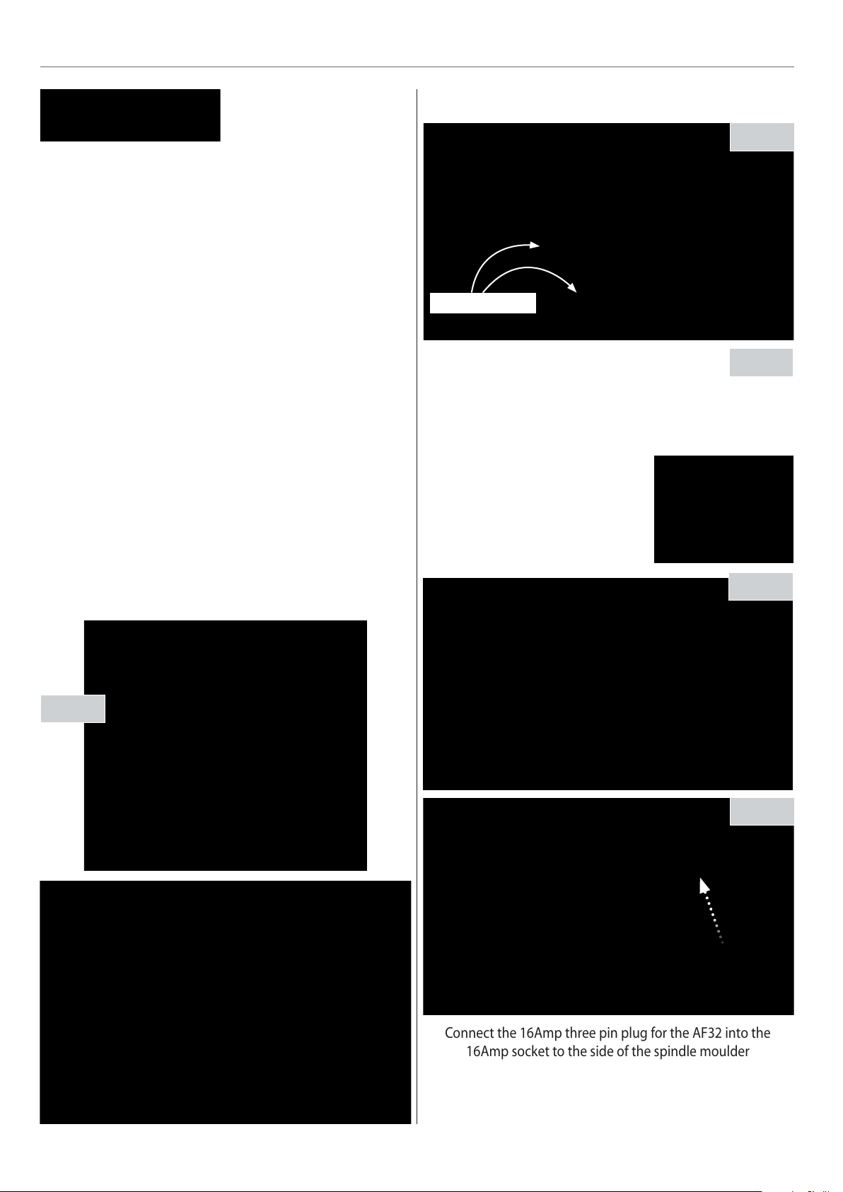
Connect the 16Amp three pin plug for the AF32 into the
16Amp socket to the side of the spindle moulder
Co-Matic AF32 Junior Power Feed Code: 340195
A medium weight power feed unit with three PU rollers, all
spring-loaded to provide a constant feed rate for many
machining or cutting tasks. There is a choice of four feed speeds,
easily selectable by removing the side plate and re-positioning
the drive gears. Reverse feed is available via a selection switch.
The horizontal and vertical position of the drive head can be
precisely adjusted with the aid of the two adjusting screws
and then securely locked in place with the two handles. An
additional feature is the ability to rotate the head through 90°
so that pressure can be applied to the work in either the
vertical or horizontal planes. The unit is secured to the table
of the machine, by bolting through or by screwing into holes
tapped into the machine bed, see fig 72.
Co-Matic Power Feed Assembly
Step 1
Mounting holes
Step 2
NOTE: The Co-Matic AF32 comes with a standard 13Amp
plug. You need to remove this plug and wire in the 16Amp
three pin plug that comes with the spindle moulder. This
should be done by a competent electrician.
• 240W motor fitted with reverse
• Feed speeds 5, 8, 9 & 11m/min
• Max height under rollers 150mm
• Max reach 260mm
• Column Diameter 40mm
Fig 72
Step 3
Step 4
28
Page 29
WARNING!! DISCONNECT THE MACHINE
FROM THE MAINS BEFORE CONTINUING!
• Keep the cutter block clean and free from dust build up.
ROUTINE MAINTENANCE
• Opening the access door for the spindle moulder, check
the belt tension. If the belt is loose, using the 16mm socket
spanner loosen the motor bolts and push/pull until the belt
is under tension again, tighten the motor bolts to keep the
tension.
• Check the cutter block regularly for chipped blades and
damage to block i.e cracks in the cutter block.
• When changing the cutter block, remove the cutter
block and place safely away, clean the spindle by
spraying a light coating of oil over the shaft and install
a new cutter block.
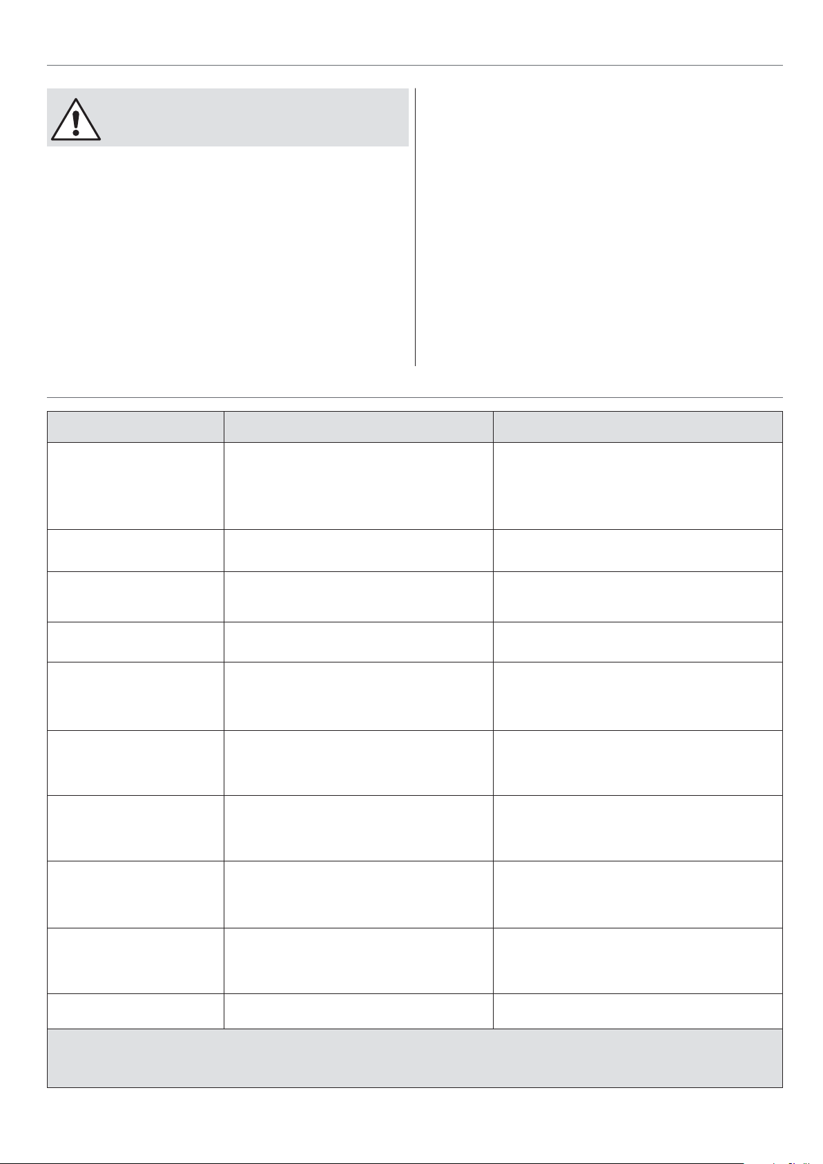
TROUBLE SHOOTING CHART
Problem Cause Solution
Motor is slow or weak Voltage from source is low
Windings are burned out or open
Power switch is defective
Circuit is overloaded with appliance, lights or other
electrically power equipment
Motor overheats Motor is overloaded
Blunt cutting tool
When cutting the cutter burns
the work-piece or stalls the
motor
Spindle tilt and height handles
are hard to turn
Cutting tool is blunt
Work-piece is warped
Tilt locking handle is not fully released
Spindle height handle is not fully released
• After several months of constant use the condition of
the chains, sprockets,tension of the drive belts and the
threaded drive shafts of the rise and fall tilt mechanisms
will need to be checked. That may require a service
engineer to oversee the job.
If you find that the machine is not performing as it should
please contact our “Technical Sales Team” by phone on 03332
406406.
Check the voltage from your electricity supplier
Have the Motor checked/repaired
Have the power switch replaced
DO NOT use other appliances on the same circuit when
using this machine
Check the voltage from your electricity supplier
Replace the cutting tool
Replace the cutting tool
Replace the work-piece
Release tilt locking handle
Release height locking handle
Spindle moulder vibrates
excessively
Spindle moulder does not start upMotor power cord is not plugged in
Power switch does not function Power switch contacts are burned out
Fuses or circuit breakers open
frequently
Motor stalls, blows fuses or trips
the circuit breakers
Spindle moulder is noisy when
in operation
Floor surface is uneven
V-belt is damaged
Milling tool is damaged
Loose bolt, screws and nuts
Circuit fuse is blown
Circuit breaker is tripped
Motor power cord or switch is damaged
Capacitor is defective
Wiring connections are loose or damaged
Motor is overloaded
Fuses or curcit breakers are the wrong size or defective
Blunt cutting tool
Power switch is defective
Motor is overloaded
Blunt cutting tool
Fuses or circuit breakers are the wrong size or defective
Feeding work-piece too rapidly
Motor is loose or defective Have the motor checked or replaced
WARNING! To prevent personal injury or damage to the spindle moulder, maintenance
and other repairs should be carried out by a qualified technician.
(Contact Axminster Tools & Machinery on 0800 371822)
Adjust each leg in turn until machine is level
Replace the V-belt
Replace the cutting tool
Tighten all fixing
Plug in the motor power cord into the socket and switch on
Replace the circuit fuse
Reset the circuit breaker
Have the motor power cord or switch replaced
Have the power switch replaced
Check the voltage from your electricity supplier
Have the capacitor replaced
Have the wiring connections checked/replaced
Feed work-piece more slowly
Replace fuses or circuit breakers
Replace the cutting tool
Have the power switch replaced
Check the voltage from your electricity supplier
Replace the cutting tool
Replace fuses or circuit breakers
Feed the work-piece through more slowly
29
Page 30
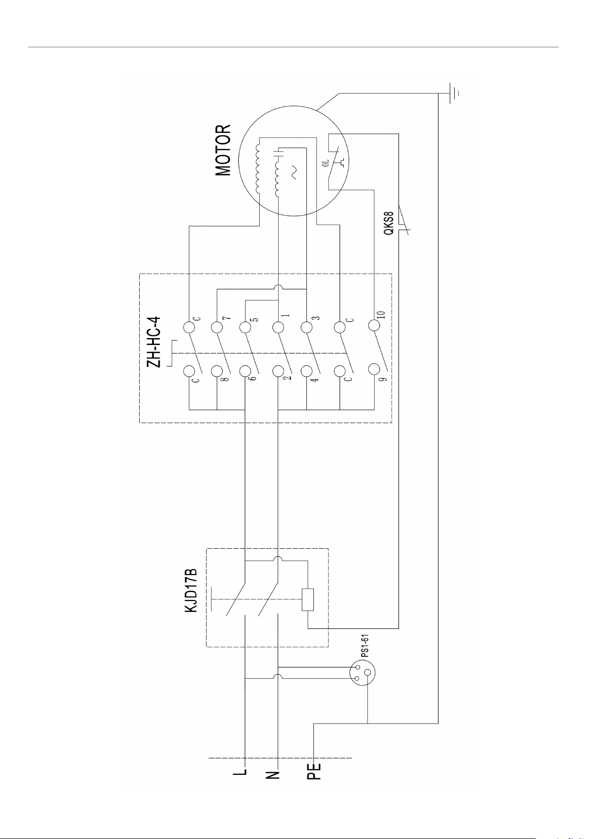
WIRING DIAGRAM
30
Page 31

EXPLODED DIAGRAMSLIST
No. DESCRIPTION Qty
1 Spindle shaft 1
2 Spindle ring 50x30x30mm 1
3 Spindle ring 50x30x 10mm 1
4 Cutting tool 1
5 Lock flange 1
6 Allen bolt M12x25 1
7 Allen wrench 10mm 1
8 Spindle ring 50x30x20mm 1
9 Spindle ring 50x30x10mm 1
10 Spindle ring 50x30x5mm 4
31
Page 32
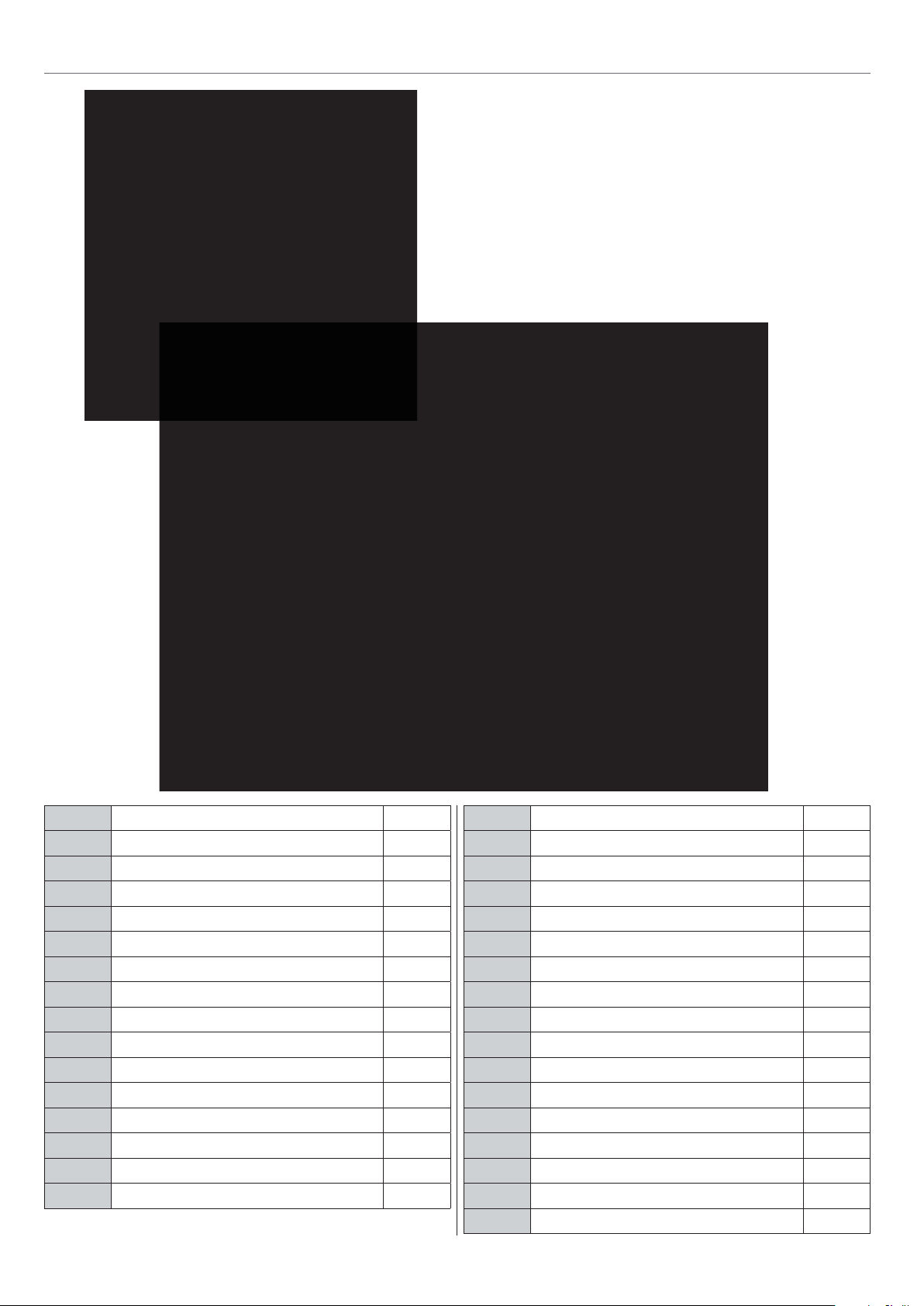
EXPLODED DIAGRAMSLIST
No. DESCRIPTION Qty
A-1 Safe guard 1
A-2 Table 1
A-3 Allen bolt M10x70 4
A-4 Mill drive set 1
A-5 Lock nut M10 12
A-6 Flat washer 10mm 8
A-7 Scutcheon 1
A-8 Workstand 1
A-9 Spindle height display 1
A-10 Main switch (No-volt release) 1
A-11 Switch(QKS8) 1
A-12 Cross recessed pan head screw M4x30 2
A-13 Left panel, machine housing 1
A-14 Startype screw M8x15 1
A-15 Lock nut M12 4
A-16 Thrust bearing 8101 2
A-17 Swing arm 1
A-18 Lock nut M16 1
A-19 Sliding bench (optional) 1
A-20 Guide rail 1
A-21 Sliding rail 1
A-22 Workpiece Clamp 1
A-23 Allen bolt M 12x65 2
A-24 Carriage bolt, M8x45 2
A-25 Lock nut M8 4
A-26 Guide, bolt 2
A-27 Allen bolt M8x16 4
A-28 Lock nut M12 2
A-29 End stop, guide 2
A-30 Hex head screw M5x16 4
A-31 Hex head screw M6x50 2
A-32 Lock nut M6 2
32
Page 33

EXPLODED DIAGRAMSLIST
33
Continues Over...
Page 34
EXPLODED DIAGRAMSLIST
NO. DESCRIPTION QTY
1 Cross recessed pan head screw M5x16 2
2 Cross recessed pan head screw M5x12 2
3 Dust outlet 1
4 Hexagonal screw M5X16 4
5 Adjusting handwheel 2
6 Plate 2
7 M5 nut 4
8 Locking block 2
9 Nut 2
10 Locking handle 2
11 Safe guard 1
12 Guide spindle, spindle latch 2
13 Locking handwheel 2
14 Flat washer 8 2
15 Fence extrusion carriage 2
16 Batten 4
17 Guide 2
18 Carriage bolt 2
19 Fence extrusion 2
20 Locking screw 8
21 Locking handle 2
22 Flat washer 8 2
23 Base plate 1
24 Hinge 1
25 Safe guard cover 1
26 Holddown clamp 1
27 Spring plate 1
28 screw 2
29 Hexagon bolt 4
30 Anti-kickback plate 1
31 Vertical Rod 1
32 Spring plate 1
33 Locking handle 1
34 End cap 1
35 Cap nut 1
36 Hexagonal rod 1
37 Clamping plate 1
38 Spring plate 1
39 Locking handle 1
40 Locking handle 1
41 Long spring plate 1
42 Cross rod 1
43 Bracket 1
44 Hexagon socket bolt 6
45 Flat washer 8 6
46 Cross recessed countersunk head screw 2
47 Cross recessed countersunk head screw 2
48 End cap 1
Supplied By Axminster Tools Ltd
49 Fence Top Guard 1
50 Fence Carriage Right Guard 1
51 Fence Carriage Left Guard 1
34
Page 35

EXPLODED DIAGRAMSLIST
No. DESCRIPTION Qty
C-1 Tilting set 1
C-2 Support, swivel turnion 2
C-3 Swivel guide 1
C-4 Swivel, turnion 2
C-5 Lockup seat 1
C-6 Allen bolt M10x35 2
C-7 Allen bolt M8x 16 2
C-8 Flat washer 12mm 1
C-9 Lockup shaft 1
C-10 Tilt locking lever 1
C-14 Tilt locking block 1
C-15 Lockup seat 1
C-16 Spindle shaft set 1
C-17 Swivel head 1
C-18 Allen bolt M10x35 4
C-19 Spring washer 10mm 4
C-20 Flat washer 10mm 4
C-21 Allen bolt M6x20 4
C-22 Joint, swivel rod 1
C-23 Elevator 1
C-24 Allen bolt M8x20 4
C-25 Allen bolt M10x16 1
C-26 Big flat washer 10mm 1
C-27 Allen bolt M12x30 1
C-28 Allen bolt M8x20 2
C-29 Hex head screw M8x16 1
C-30 Spindle pulley 1
C-31 Flat key 8x8x25 1
C-32 V-belt 1
C-33 Allen bolt M10x45 1
C-34 Motor set 1
C-35 Allen bolt M10x16 1
C-36 End stop, guide 1
C-37 Allen bolt M10x45 4
C-38 Nut, swivel rod 1
C-39 Nut fix rod 4
35
Page 36
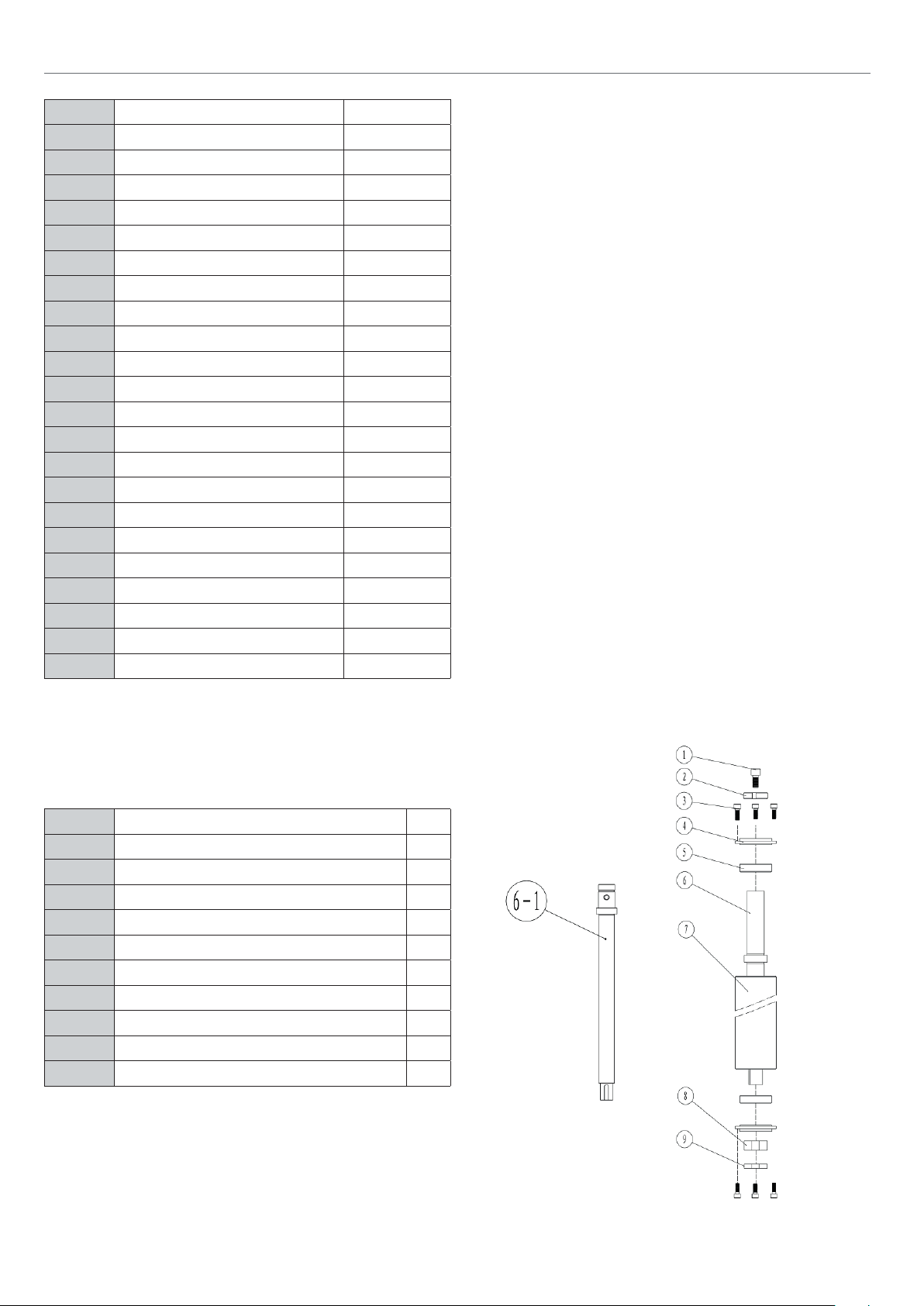
EXPLODED DIAGRAMS/LIST
No. DESCRIPTION Qty
D-1 Countersunk head screw M5x12 1
D-2 Large washer 6mm 1
D-3 Wheel handle 1
D-4 Large washer 12mm 1
D-5 Pear plate, lock lever 1
D-6 Hex bolt M6x25 1
D-7 Bushing pointer 1
D-8 Lock lever rise 1
D-9 Rise shaft 1
D-10 Housing rise shaft 1
D-11 Hex bolt M8x25 4
D-12 Spring washer 8mm 4
D-13 Ball bearing 80202 1
D-14 Bushing worm 1
D-15 Worm 1
D-16 Carrier rise gear 1
D-17 Gear-helical 1
D-18 Bushing, spindle 1
D-19 Thrust bearing 8105 1
D-20 Special washer 1
D-21 Thin hex nut M20 2
D-22 Rising spindle 1
No. DESCRIPTION Qty
E-1 Allen bolt M12x25 1
E-2 Lock ange 1
E-3 Allen bolt M4x16 8
E-4 Cup spindle guide tube 2
E-5 Ball bearing 80106 2
E-6 Spindle shaft A 1
E-6-1 Spindle shaft B 1
E-7 Spindle guide tube 1
E-8 Lock nut M30 1
E-9 Lock nut M30 1
36
Page 37

No. DESCRIPTION Qty
F-1 Countersunk head screw M5x12 1
F-2 Large washer 6mm 1
F-3 Wheel handle 1
F-4 Circle 9mm 1
F-5 Pin cone gear 1
F-6 Ball bearing 619/8 2
F-7 Circle 19mm 1
F-8 Gear base 1
F-9 Bushing worm 1
F-10 Roll pin 3x16 1
F-11 Gimbal 1
F-12 Swivel rod 1
No. DESCRIPTION Qty
G-1 Hex bolt M10x15 1
G-2 Flat washer 10mm 1
G-3 Guide bar 1
G-4 Joint tension 1
G-5 Flat washer 16mm 1
G-6 Hex nut M16 1
G-7 Thread joint 1
G-8 Lock nut M10 1
G-9 Joint motor tension 1
G-10 Thread tension 1
G-11 Lock nut M10 3
G-12 Lever tension 1
G-13 Circle 24mm 1
G-14 Motor pulley 1
G-15 Large washer 10mm 1
G-16 Hex bolt M10x20 1
G-17 Hex head screw M12x40 1
G-18 Mount, motor 1
G-19 Motor 1
G-20 Hex nut M12 1
EXPLODED DIAGRAMSLIST
37
Page 38
EXPLODED DIAGRAMSLIST
No. DESCRIPTION Qty
H-1 Cross recessed pan head screw M4x12 2 2
H-2 Switch KJD17B-16 1
H-3 Switch Batten 1
H-4 ZH-HC-3 switch 1
H-5 Nut M20 1
H-6 Electrical wire 1
No. DESCRIPTION Qty
I-1 Guide bar 1
I-2 End cap 2
I-3 Telescopic arm 1
I-4 Hex bolt M6x12 4
I-5 Circle 24mm 8
I-6 Ball bearing 61901 8
I-7 Partiality shelf 4
I-8 Wheel 4
I-9 Telescopic arm 1
I-10 Hex bolt M6x12 1
I-11 Cross recessed pan head screw M5x12 8
I-12 End cap 2
I-13 Hex bolt M6x12 1
I-14 Washer 6mm 1
I-15 Guide bolt, bolt A 1
I-16 Guide bolt, bolt B 1
I-17 Guide bolt, bolt C 1
I-18 Swing arm 1
I-19 Guide bar 1
I-20 Hex bolt M6x12 1
38
Page 39

EXPLODED DIAGRAMSLIST
No. DESCRIPTION Qty
J-1 End cap 1
J-2 Guide rail 1
J-3 Staff gauge A 1
J-4 Stop rail 1
J-5 Seat A 1
J-6 Convex 1
J-7 Flower handle 1
J-8 Spring washer 6mm 1
J-9 Seat B 1
J-10 Staff gauge B 1
J-11 Block 1
J-12 End stop 1
J-13 Slaver 1
J-14 Countersunk head screw M6x30 2
J-15 Bolt guide 1
J-16 Spring washer 6mm 1
J-17 Flower handle 1
J-18 Block 1
J-19 Seat C 1
J-20 Flower handle 1
J-21 Intermediate plate 1
J-22 Spring washer 6mm 1
J-23 Ratchet lever M6 1
J-24 Roll 1
39
Page 40

EXPLODED DIAGRAMSLIST
No. DESCRIPTION Qty
K-1 Sliding bench 1
K-2 Tilt lock 2
K-3 Spring washer 6mm 2
K-4 Bolt guide 1
No. DESCRIPTION Qty
L-1 Table ring 200mm for tilt 1
L-2 Table ring 110/80mm 1
L-3 Table ring 150/110mm 2
L-4 Table ring 200/150mm 1
L-5 Flange 1
L-6 Collet 1
L-7 Spindle shaft 1
Spindle Stop Assembly
No. DESCRIPTION Qty
1 M16 Nut 2
2 Bush 1
3 Spring 1
4 Spring pin 1
5 Locating pin 1
40
Page 41

DECLARATION OF CONFORMITY
Axminster Tool Centre Ltd
EC DECLARATION OF CONFORMITY
‘original’
Product model: AP200SM Spindle Moulder
Name and address of the manufacturer: Axminster Tool Centre Ltd, Unit 10 Weycroft Avenue,
Axminster, Devon EX13 5PH, United Kingdom
This declaration of conformity is issued under the sole responsibility of the manufacturer.
Object of the declaration: AP200SM Spindle Moulder
The object of the declaration described above is in conformity with the relevant GB legislation:
Supply of Machinery (Safety) Regulations 2008 as amended.
Electromagnetic Compatibility Regulations 2016 as amended.
References to the relevant harmonised standards used or references to the other technical
specifications in relation to which conformity is declared:
EN ISO 12100:2010 Safety of Machinery. General principles for design. Risk assessment and
risk reduction.
EN ISO 19085-6:2017 Woodworking machines. Safety. Single spindle vertical moulding
machines (“toupeis”)
EN 60204-1:2018
Safety of machinery - Electrical equipment of machines - General
requirements.
EN 61000-6-1:2007 Electromagnetic compatibility (EMC). Generic standards. Immunity for
residential, commercial and light-industrial environments.
EN 61000-6-3:2007 Electromagnetic compatibility (EMC). Generic standards. Emission
standard for residential, commercial and light-industrial environments.
Additional information:
Name and address of person authorised to compile the technical file: Axminster Tool Centre
Ltd, Unit 10 Weycroft Avenue, Axminster, Devon EX13 5PH, United Kingdom
The machinery fulfils all relevant provisions of Supply of Machinery (Safety) Regulations 2008
as amended.
Signed for and behalf of: Axminster Tool Centre Ltd;
(place and date of issue): Axminster, Devon, United Kingdom Kingdom, 23
(name, function): Andrew Parkhouse, Supply Chain Director
Signature: ………………………………………………………………
41
rd
May 2023
Page 42

DECLARATION OF CONFORMITY
Axminster Tool Centre Ltd
UK DECLARATION OF CONFORMITY
Product model: AP200SM Spindle Moulder
Name and address of the manufacturer: Axminster Tool Centre Ltd, Unit 10 Weycroft Avenue,
Axminster, Devon EX13 5PH, United Kingdom
This declaration of conformity is issued under the sole responsibility of the manufacturer.
Object of the declaration: AP200SM Spindle Moulder
The object of the declaration described above is in conformity with the relevant GB legislation:
‘original’
Supply of Machinery (Safety) Regulations 2008 as amended.
Electromagnetic Compatibility Regulations 2016 as amended.
References to the relevant harmonised standards used or references to the other technical
specifications in relation to which conformity is declared:
.
EN ISO 12100:2010 Safety of Machinery. General principles for design. Risk assessment and
risk reduction.
EN ISO 19085-6:2017 Woodworking machines. Safety. Single spindle vertical moulding
machines (“toupeis”)
EN 60204-1:2018
requirements.
EN 61000-6-1:2007 Electromagnetic compatibility (EMC). Generic standards. Immunity for
residential, commercial and light-industrial environments.
EN 61000-6-3:2007 Electromagnetic compatibility (EMC). Generic standards. Emission
standard for residential, commercial and light-industrial environments.
Additional information:
Name and address of person authorised to compile the technical file: Axminster Tool Centre
Ltd, Unit 10 Weycroft Avenue, Axminster, Devon EX13 5PH, United Kingdom
The machinery fulfils all relevant provisions of Supply of Machinery (Safety) Regulations 2008
as amended.
Safety of machinery - Electrical equipment of machines - General
Signed for and behalf of: Axminster Tool Centre Ltd;
(place and date of issue): Axminster, Devon, United Kingdom, 23
(name, function): Andrew Parkhouse, Supply Chain Director
Signature: ………………………………………………………………
rd
May 2023
42
Page 43

Page 44

The Axminster guarantee
Buy with confidence from Axminster Tools!
So sure are we of the quality, we cover all parts and labour free of charge for three years!
For more information visit axminstertools.com/3years
The packaging is suitable for recycling.
Please dispose of it in a responsible manner.
EU Countries Only
Do not dispose of electric tools together with household waste material.
By law they must be collected and recycled separately.
Axminster Tools, Axminster Devon EX13 5PH
axminstertools.com
 Loading...