

Page 1
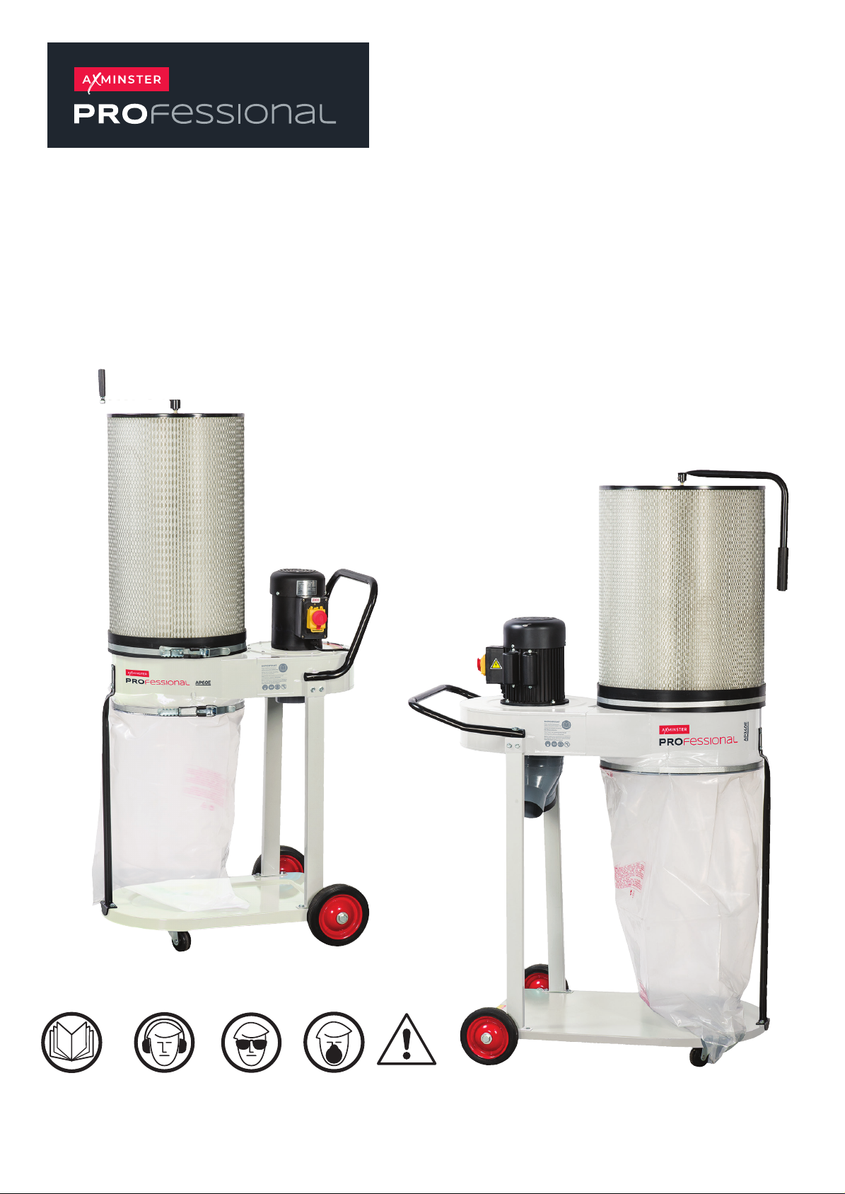
AP60E & AP170E
Extractors
AP60E Code 107632
AP170E Code 107633
Original Instructions
AP60E
AP170E
The symbols below advise the correct safety procedures when using this machine.
Fully read manual
and safety instructions
before use
Ear protection
should be worn
Eye protection
should be worn
Dust mask
should be worn
HAZARD
AT: 29/7/2025
BOOK VERSION: 8
Page 2
INDEX OF CONTENTS
EU Declaration of Conformity 02
What’s Included 03-06
General Instruction for 230V Machines 07
Specic Safety for Dust Extractors 07
Specication 08
Assembly 08-14
Illustration and Parts Description 15-14-15-16-17-18
Operating Instruction 19
Ducting System 20
Maintenance 20
Weekly LEV System Maintenance Log 21-22
LEV Testing 23
Extraction Accessories 23
Exploded Diagrams/Parts Lists 24-25-26-27-28-29
Wiring Diagram 29
Notes 30-31
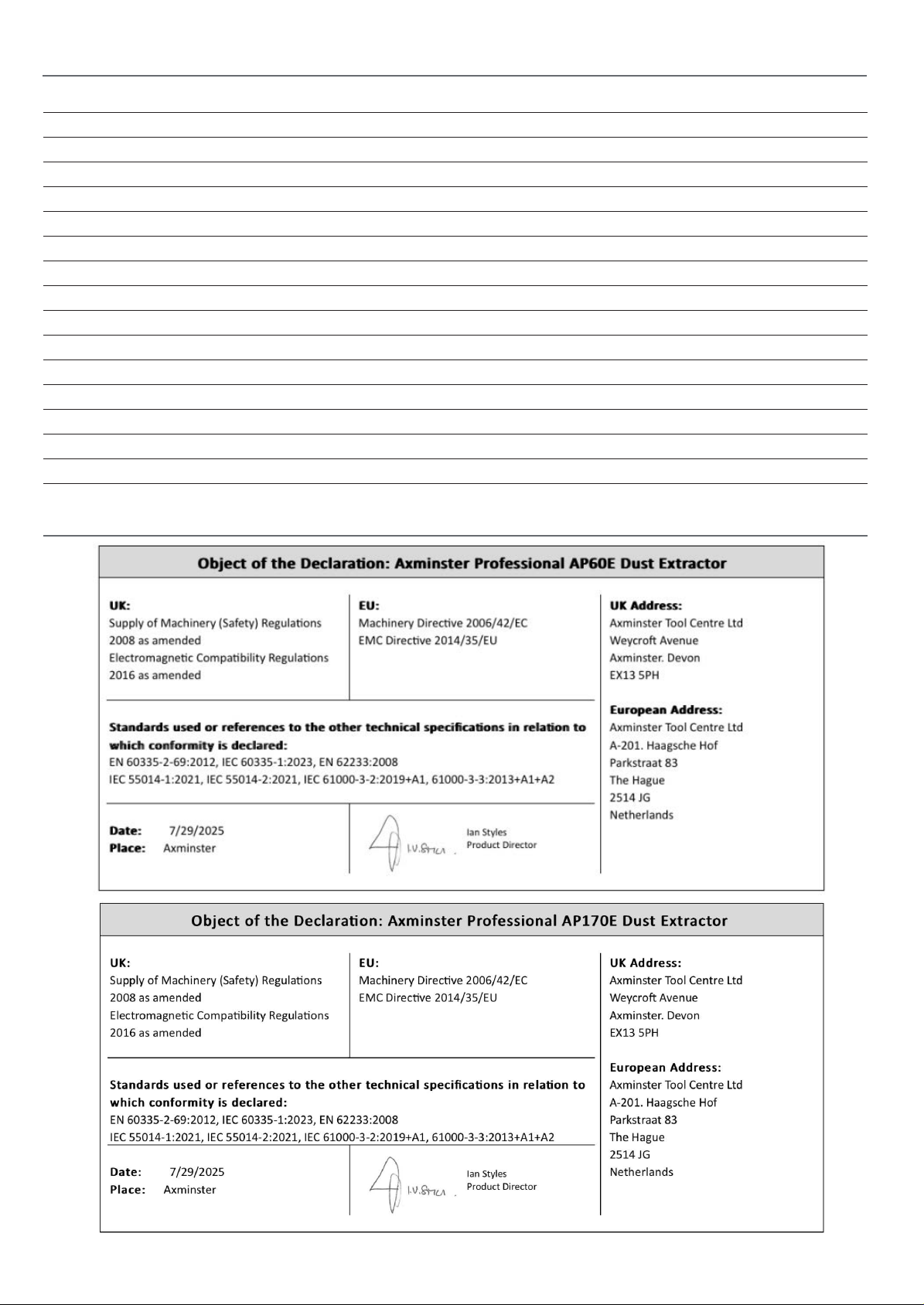
EU DECLARATION OF CONFORMITY
2
Page 3
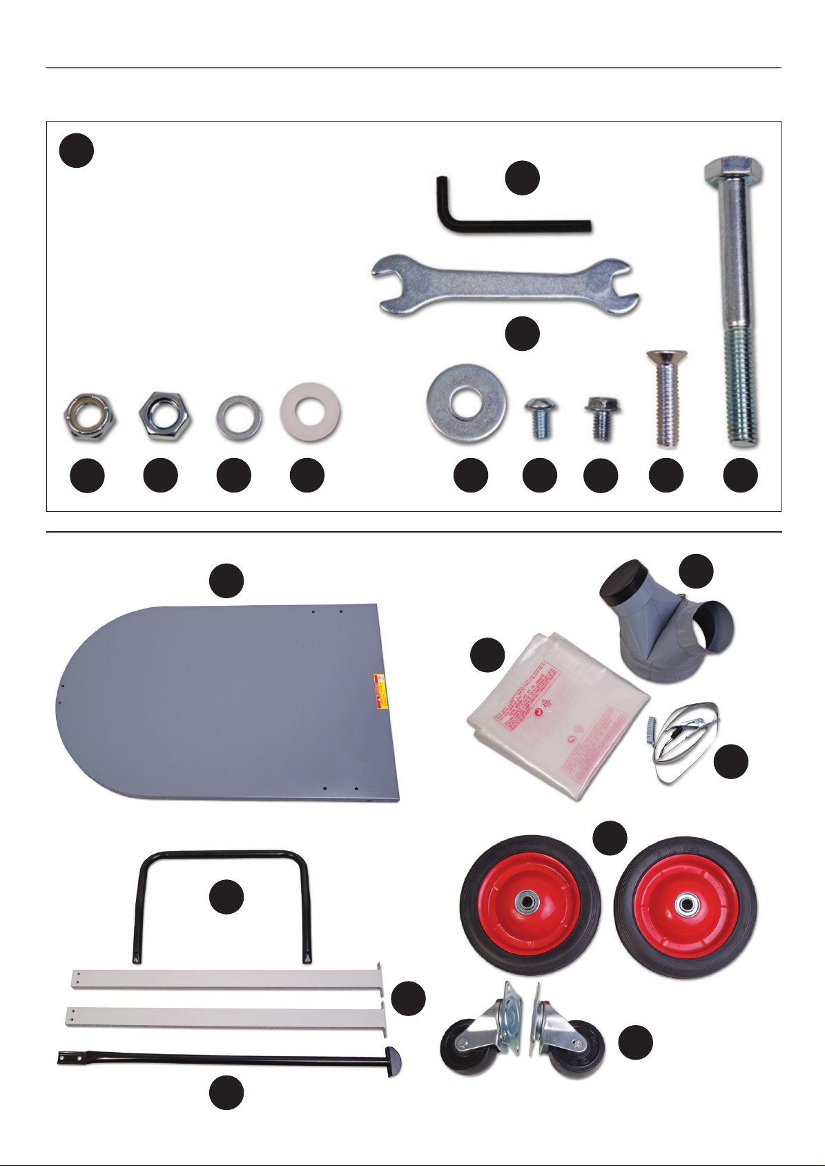
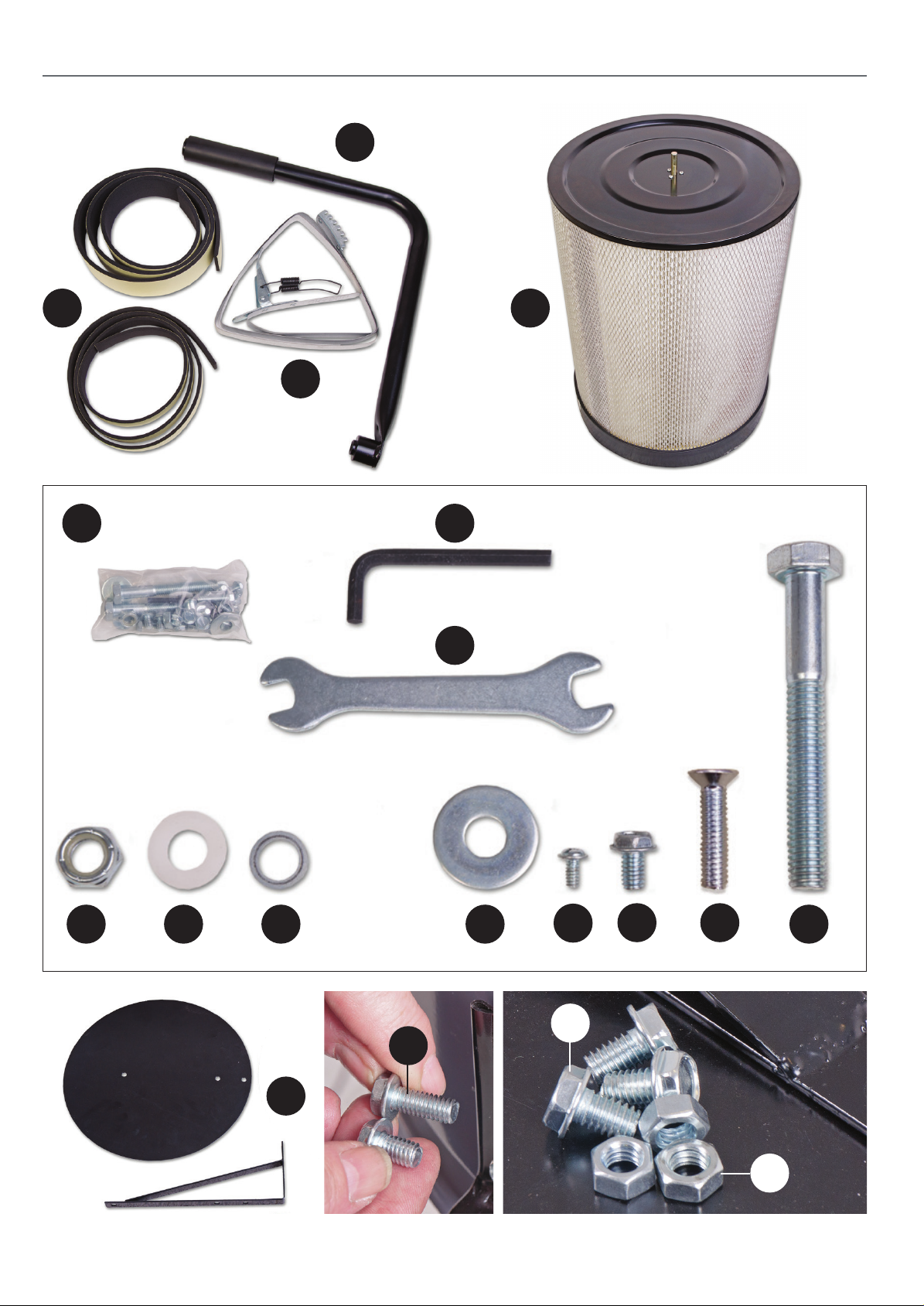
WHAT’S INCLUDED
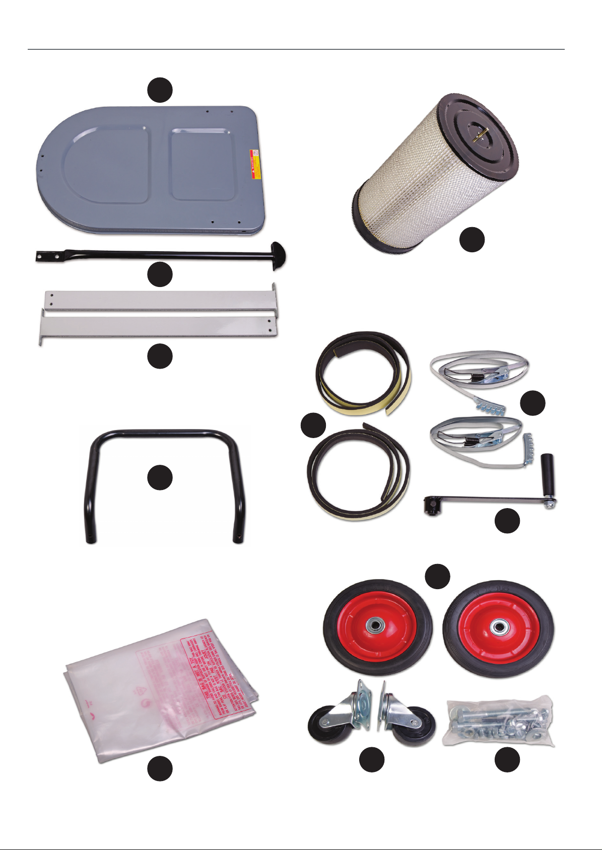
Model Number AP60E
Quantity Item Part
107632
1 Base 1
1 Tube Support Bar 2
2 Upright Supports 3
1 Tube Handle 4
1 Filter Dust Bag 5
1 Filter Assembly 6
2 Foam Seal Bands 7
2 Filter and Bag Retaining Belts 8
1 Shaker Paddle Operating Handle 9
2 Wheels 10
2 Castor Wheels 11
Extractor Fixings 12
1 5mm Hex Key a
1 10-12mm Spanner b
2 1/2" Lock Nut c
2 1/2" Nuts d
2 Thin Washers e
2 Nylon Washers f
2 Large Washers h
8 5/16" UNC Domed Cap head Bolts i
12 5/16" UNC Hex Bolts (Short) j
2 5/16" UNC Countersink Bolts (Long) k
2 1/2" Large Hex Bolts l
1 Extractor Assembly 13
Model Number AP170E
Quantity Item Part
107633
1 Base 14
1 Tube Handle 15
1 Upright Support 16
1 Tube Support Bar 17
1 Inlet Manifold 18
1Filter Dust Bag 19
1 Filter Bag Retaining Belt 20
2 Wheels 21
2 Castor Wheels 22
1 Shaker Paddle Operating Handle 23
1 Filter Retaining Belt 24
2 Foam Seal Bands 25
1 Filter Assembly 26
Extractor Fixings 27
1 5mm Hex Key a
1 10-12mm Spanner b
2 1/2” Lock Nut c
2 Nylon Washers d
2 Thin Washers e
2 Large Washers g
1 Small Phillips Screw No: 10 ANC h
18 5/16" UNC Hex Bolts (Short) i
2 5/16” UNC Countersink Bolts (Long) j
2 1/2” Large Hex Bolts k
1 Extractor Assembly 28
1 Dust Deflector with angle bracket 29
3 Hex Bolts (Short) l
5 5/16” Nuts m
2 5/16 UNC Hex Bolts (Long) n
13
Please read the Instruction Manual prior to using your new
machine. As well as the operating procedures for your new
machine, there are numerous hints and tips to help you to
use the machine safely and to maintain its efficiency and
prolong its life. There is also a detailed description of the
parts of your Extractor, which will enable you to become
familiar with terminology we will use in this manual. Keep
this Instruction Manual readily accessible for any others
who may also be required to use the machine.
28
3
Page 4
WHAT’S INCLUDED
AP60E Extractor
1
2
6
3
4
8
7
9
10
5
11 12
4
Page 5
AP60E Extractor
12
WHAT’S INCLUDED
a
b
c
AP170E Extractor
d e f h i
14
19
j
21
k l
18
20
15
17
16
5
22
Continues Over....
Page 6
WHAT’S INCLUDED
AP170E Extractor
23
25
24
27 a
26
b
c d e g
n
29
6
h
l
i j
k
m
Page 7
GENERAL INSTRUCTION FOR 230V MACHINES
The following will enable you to observe good working
practices, keep yourself and fellow workers safe and maintain
your tools and equipment in good working order.
WARNING!! KEEP TOOLS AND EQUIPMENT
OUT OF REACH OF YOUNG CHILDREN
KEEP WORK AREA AS UNCLUTTERED AS IS
PRACTICAL. UNDER NO CIRCUMSTANCES SHOULD
CHILDREN BE ALLOWED IN WORK AREAS.
Mains Powered Tools
• The machine is supplied with an attached 16 Amp plug.
• Inspect the cable and plug to ensuree that neither are
damaged. Repair if necessary by a suitably qualified person.
• Do not use when or where it is liable to get wet.
N.B. This Machine requires a 16amp supply and it’s
recommended that a C Type breaker is used, if you are
unsure please contact a qualified electrician.
Workplace
• Do not use 230V a.c. powered tools anywhere
within a site area that is flooded.
• Keep machine clean.
• Leave machine unplugged until work is about to commence.
• Always disconnect by pulling on the plug body and not the
cable.
• Carry out a final check e.g. check the cutting tool
is securely tightened in the machine and the correct
speed and function set.
• Ensure you are comfortable before you start work,
balanced, not reaching etc.
• Wear appropriate safety clothing, goggles, gloves,
masks etc. Wear ear defenders at all times.
• If you have long hair wear a hair net or helmet to prevent it
being caught up in the rotating parts of the machine.
• Consideration should be given to the removal of rings and
wristwatches.
• Consideration should also be given to non-slip footwear etc.
• If another person is to use the machine, ensure they are
suitably qualified to use it.
• Do not use the machine if you are tired or distracted
• Do not use this machine within the designated safety areas
of flammable liquid stores or in areas where there may be
volatile gases.
• Check cutters are correct type and size, are undamaged
and are kept clean and sharp, this will maintain their
operating performance and lessen the loading on the
machine.
• OBSERVE…. make sure you know what is happening
around you and USE YOUR COMMON SENSE.
SPECIFIC SAFETY FOR DUST EXTRACTORS
Do not use this machine as a vacuum cleaner, try to keep the
waste medium to wood by products.
Do not uplift workshop floor debris (stones, nails, screws, paper
etc., etc). Be aware that wood dust is an explosive medium.
Do not allow any ‘naked light’ source to occur anywhere near
the machine. This includes cigarettes, matches, etc, and do not
place the machine near any unprotected light bulbs, that could
possibly get broken.
The suction force is generated by a high speed fan unit. This
has the potential to amputate fingers, grab loose clothing (ties
etc.,) and ‘bat’ large chips etc, at high speeds. Keep all guarding
in place, and if access to the fan becomes necessary (due to
blockage etc.,) Disconnect the machine from the mains supply
and ensure the fan has come to a complete stop before putting
your hands anywhere near to it.
If you are not using ‘clear’ extraction hose, periodically remove
the hose to check that the inlet to the machine is not get
ting restricted. (The safety guard grill of the inlet duct can be
particularly irksome in this way, as long strand shavings etc., can
wrap around the grill fret.)
Keep the particle filter clean. The machine relies on its ability
to ‘blow’ air through the filter, to generate good suction. If the
particle filter starts to clog, this reduces the air flow and hence
the machine becomes less efficient.
-
Be aware that in dry air periods or areas, the movement of the
air through the machine can generate static electric fields.
These are not normally a problem as the machine is bonded
together via its construction and the whole is earthed back
through the electrical supply; problems can occur with isolated
items, such as stands or hosing that are insulated from the
ground (standing on rubber feet?, suspended in the air etc).
If possible, try to connect everything together electrically, to
eliminate static shocks.
(Use the integral metal coil in flexible plastic hosing to connect
units together).
Try to route the power cable and the hosing away from busy
walkways.
Do not allow the inlet to become ‘dead ended’, or block or
restrict the outlet, this puts undue strain on the motor and can
lead to overheating.
ONLY USE DUST EXTRACTION BAGS
WITH THIS MACHINE NOT DOMESTIC
WASTE BAGES!
DO NOT PLACE DUST EXTRACTION
BAGES OVER THE FILTER ASSEMBLY!
The particle filter can be cleaned, by using an ‘M’ class vacuum
cleaner, clean the inside of the filter.
7
Page 8
SPECIFICATION
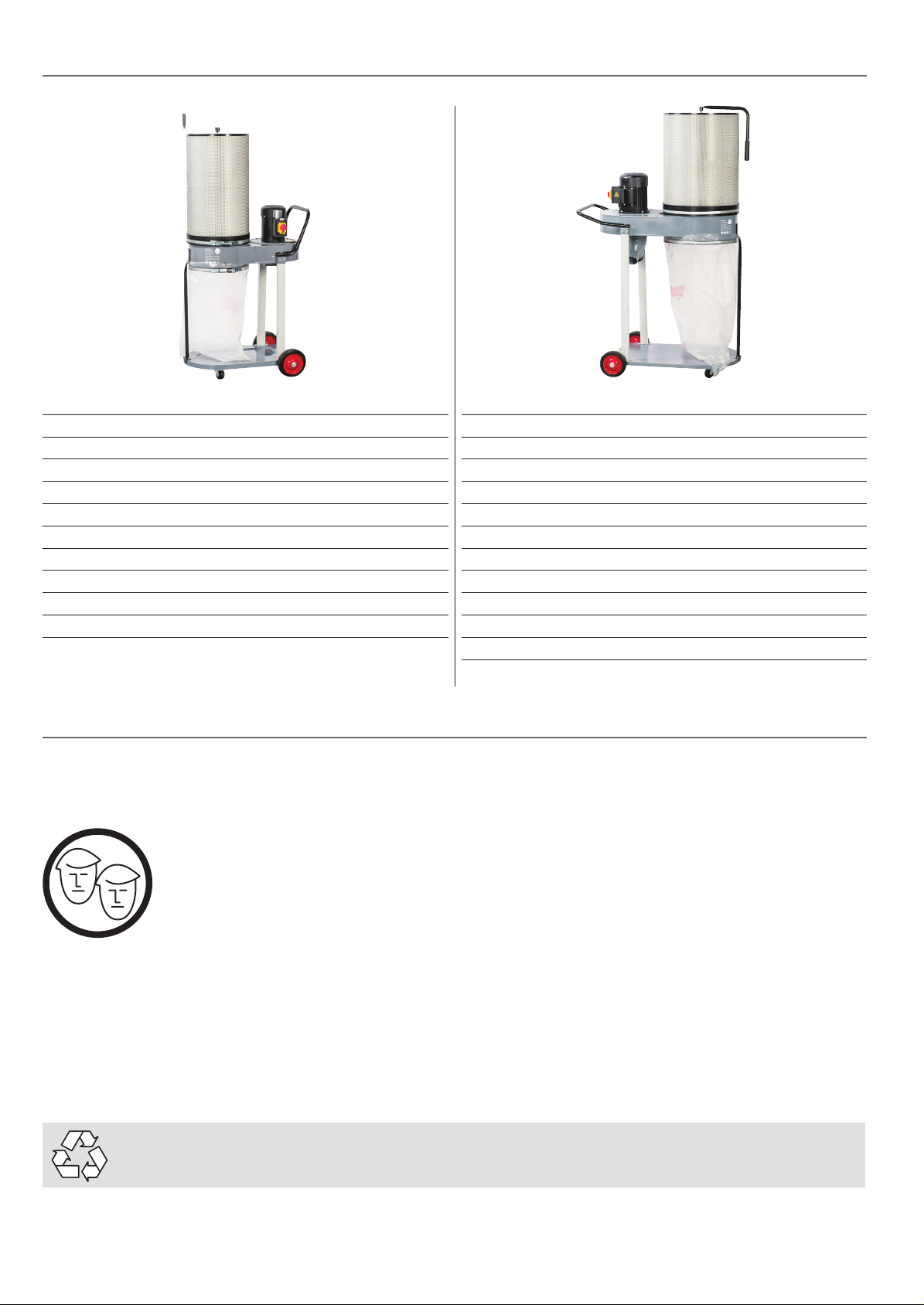
Code 107632
Model AP60E
Rating Professional
Power 0.75kW 230V 1ph
Air Flow 850 m³/h at 100 mm
Noise Level 1 Meter (Distance) 77.6dB
3 Meter (Distance) 73.3dB
Particle Size 1 micron
Hose Diameter 100 mm
Bag Capacity 60 litre
Overall L x W x H 720 x 660 x 1460 mm
Weight 27 kg
Code 107633
Model AP170E
Rating Professional
Power 1.5kW 230V 1ph
Air Flow 2,250 m³/hr at 175 mm,
1,200 m³/hr at 100 mm
Noise Level 1 Meter (Distance) 80.2dB
3 Meter (Distance) 81dB
Particle Size 1 micron
Hose Diameter 1 x 175mm, 2 x 100 mm
Bag Capacity 170 litre
Overall L x W x H 1,100 x 680 x 1,750 mm
Weight 56 kg
ASSEMBLY
Please read through the section entitled Parts Identification and Description, this will enable you to more readily
identify those parts of the cyclone extractor.
Please note: some of this assembly procedure is best accomplished by two persons. Although
the tasks are not impossible, some of the items are heavy and awkward, and a mishandling
error could cause injury. Please think about what you are doing, your capabilities and your
personal safety. We have added the ‘two person symbol’ to any operation that we recommend
should be a two person task.
Unpack all the boxes and check all the components listed in the “What’s Included” section. If any parts or components are missing,
please contact our Customer Services Department using the procedures and telephone numbers listed in our catalogue.
Please note: on occasions the packing list is not strictly adhered to. Please check all the boxes, packets
etc. to make sure that all the parts have been accounted for.
PLEASE RECYCLE ANY UNWANTED PACKAGING RESPONSIBLY!
8
Page 9
Having unpacked the boxes, put all components where they
are readily to hand.
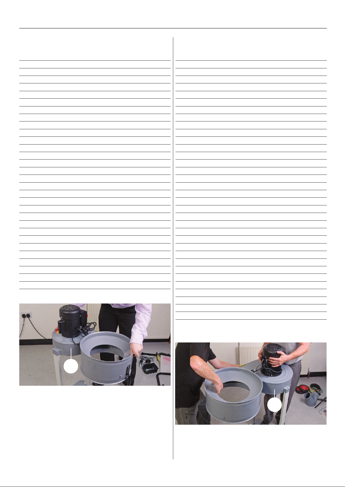
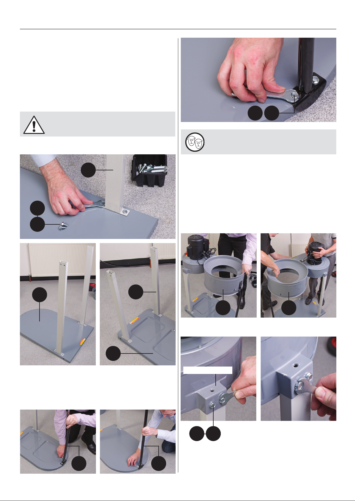
1. Locate the base (1-14), twelve UNC short bolts (12j - 27i) and
upright supports (3-16). Place one of the supports (3-16) on to
base and line up the pre-drilled holes with the ones to the side
of the base, lightly secure in place with two UNC bolts, see fig
01-02-03. Repeat for the remain support.
Note: Make sure the two holes to the top of the
supports face outwards!
Fig 01-02-03
16
ASSEMBLY
12j 27i
note: You will require assistance for the next
step!
3. Locate the extractor assembly (13-28), lower the assembly
down and insert the two upright supports into the extractors
mounting brackets to either side of the assembly,
see fig 07-08-09.
12j
27i
14
3
1
2. Locate the tube support bar (2-17), line up the two holes
with the holes to the front of base (1-14) and lightly secure
using two UNC short bolts, see fig 04-05-06.
4. Line up the holes and secure in place using four UNC short
bolts (12j-27i) and the supplied spanner, 09-10.
Fig 07-08
13 28
Fig 09-10
Mounting bracket
Fig 04-05-06
12j 27i
172
9
Continues Over....
Page 10
ASSEMBLY
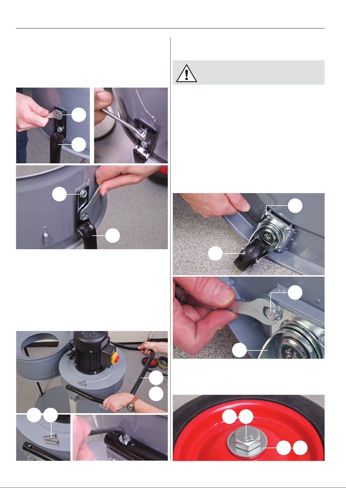
5. Locate a further two UNC short bolts (12j) and secure the
front support bar (2) to the extractor assembly (13). Secure the
support bar (17) to the extractor (28) with two UNC Hex bolts
long (n) , see fig 11-12.
Fig 11-12
n
17
12j
8. Lower the assembly down to the floor, note you may require
assistance as the motor assembly is heavy.
NOTE: USE THE HANDLE, 4-15 TO LOWER THE
EXTRACTOR TO THE FLOOR.
Wheels/ Castor Wheels
Locate the following: wheels (10-21), castor wheels (11-22),
5/16” UNC domed cap head bolts (12i) , eight 5/16” UNC Hex
bolt (27i), 1/2” nuts (12c & d), (27c), nylon washers (12f & 27d),
thin washers (12e & 27e), large washers (12h & 27g) and large
1/2" Hex bolts (12l & 27k).
1. Put to hand the castor wheels, line up the holes in the
brackets with the pre-drilled holes to the extractor’s base and
secure with domed bolts (12i) for (AP60E) and Hex bolts (27i) for
(AP170E), see fig 15-16.
Fig 15-16
12i
2
6. Locate the tube handle (4-15) and 5/16" UNC Countersink
bolts (long) (12k-27j).
7. Line up the holes in the tube handle with the threaded holes
on top of the mounting brackets, insert the countersink bolts
through the handle into the extractor assembly and secure
using a Hex key, see fig 13-14.
Fig 13-14
4
15
11
27i
22
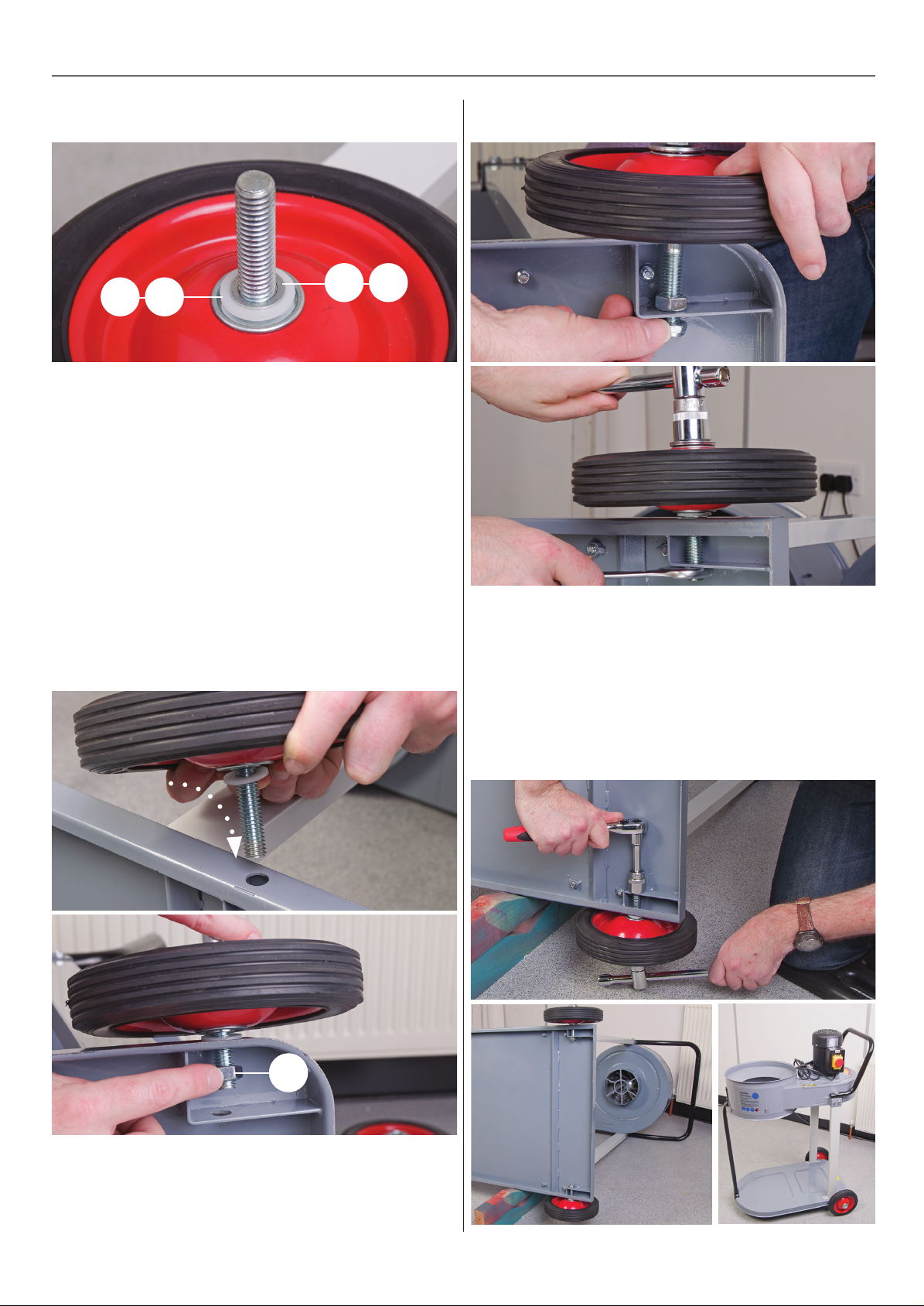
2. Place a large washer over the 1/2" hex bolts (12l & 27k)
and slide the bolt through the centre hole to the front
Fig 17
12k 27j
10
10
12l
27k
12h
27g
Page 11
ASSEMBLY
Fig 18
12e
12f
27d
of one of the wheels, see fig 17. Turn the wheel over and place
a nylon washer then a thin washer down over the thread of the
Hex bolt, see fig 18.
3. Lower the wheel assembly down and slot the hex bolt
through the pre-drilled holes to the side of the extractor’s
base, see fig 19.
AP60E Extractor Only
27e
Fig 21-22
Before sliding the Hex bolt down through the second hole,
screw on an 1/2" Hex nut (12d) onto the thread, see fig 20.
Fig 19-20
AP170E Extractor Only
Tighten the Hex nut (12d) up against the angled bracket,
see image above.
5. Repeat steps 2-4 for the remaining wheel assembly, see fig
23-24. Stand the extractor upright.
Fig 23-24
12d
4. Locate the 1/2" locking nuts (12c & 27c) and screw it onto
the thread, see fig 21 then tighten using two spanners or
open-ended sockets, see fig 22.
11
Continues Over....
Page 12
ASSEMBLY
Dust Deflector (AP170E ONLY)
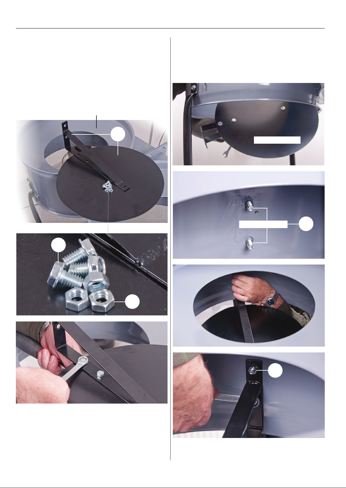
1. Locate the dust defector and bracket (29), three Hex bolts (l)
(short) and three 5/16" nuts (m). Line up the three holes in
the angle bracket with the pre-drilled holes in the deflector.
Introduce the Hex bolts (l) through the holes and secure in
place with the 5/16" nuts (m), see fig A-B-C.
Fig A-B-C
Collector
29
NOTE: Make sure the bracket is angled down wards.
Fig E-F-G-H
Dust defector
Threaded studs
n
l
m
m
2. Slot the dust defector assembly up through the centre of
collector, introduce the two pre-drilled holes in the angle
bracket over the threaded studs (n), inside the collector and
secure in place with two 5/16”nuts (m), see fig E-F-G.-H
12
Page 13
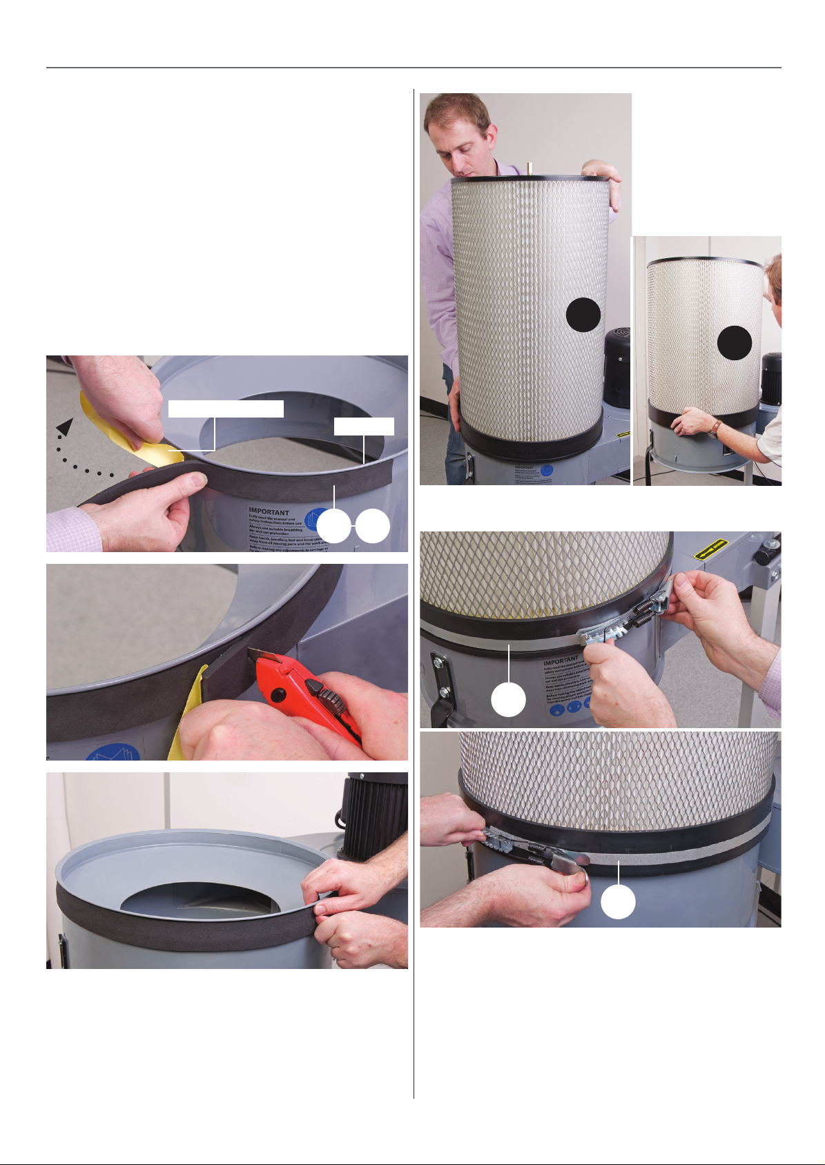
Extractor Filter
1. Locate the filter assembly ( 6-26) filter retaining belts (8-24)
and foam seal bands (7-25).
2. Put to hand the wide foam seal band, peal back the paper
backing, position the end of band up against the underside of
the upper lip on the extractor housing and firmly press down
to secure in place. Carefully peal back the backing guiding the
seal band round the extractor until it overlaps, use a knife to cut
off any excess, see fig 25-26-27.
Fig 25-6-26-27
Paper backing
Upper lip
ASSEMBLY
Fig 28
6
26
7 25
Fig 29-30
8
24
3. Go round pressing down the band to make sure it’s stuck
firmly down. Locate the filter assembly (6-26), lower the filter
down over the extractor opening until it’s firmly down, see 28.
4. Straighten the filter retaining belt (8-24), position the belt
around the base of the filter and latch it down to hold and to
seal the filter assembly, see fig 29-30.
5. Locate the remaining foam seal band, peel back the paper
backing, position the end of band up against the edge of the
lower lip of the extractor housing pressing firmily down, see
fig 31.
6. Work the band around the extractor as before, find the dust
bag (5-19) and the remaining retaining belt. Open up the dust
bag and place it up and over the lower extractor housing, see
fig 32.
13
Page 14
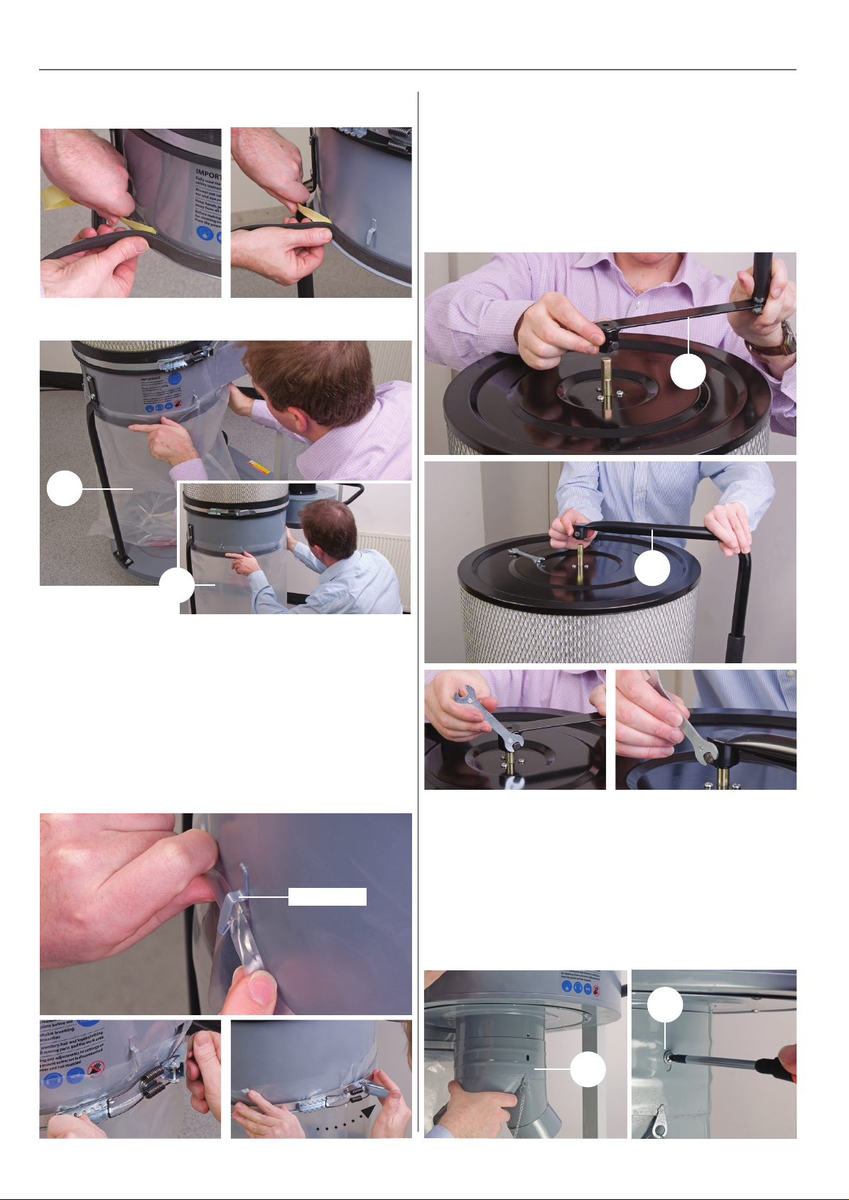
ASSEMBLY
Fig 31
Fig 32
5
Shaker Paddle Operating Handle
1. Locate the shaker paddle (9-23), insert the handle mounting
over the paddle drive shaft making sure the clamping bolt is
positioned over the machined face then tighten the bolt using
the supplied spanner to secure the handle, see fig 36-37-38.
Fig 36-37-38
9
19
7. Hook the bag onto the steel hooks around the extractor
housing to temporary hold the bag in place, see fig 33.
8. Locate the retaining belt, rap the belt around the bag making
sure the belt is positioned on top foam seal band then latch it
down to hold and to seal the bag against the extractor, see fig
34-35.
Fig 33-34-35
Bag hook
23
Inlet Manifold (AP60E Extractor Only)
Locate the inlet manifold (18) and the small Phillips screw (27h).
Insert the manifold over the extractors inlet and line up the
threaded hole in the inlet with cutout slot in the manifold, see
fig 39. Secure the manifold in place with the Phillips screw, see
fig 40.
Fig 39-40
14
14
27h
18
Page 15
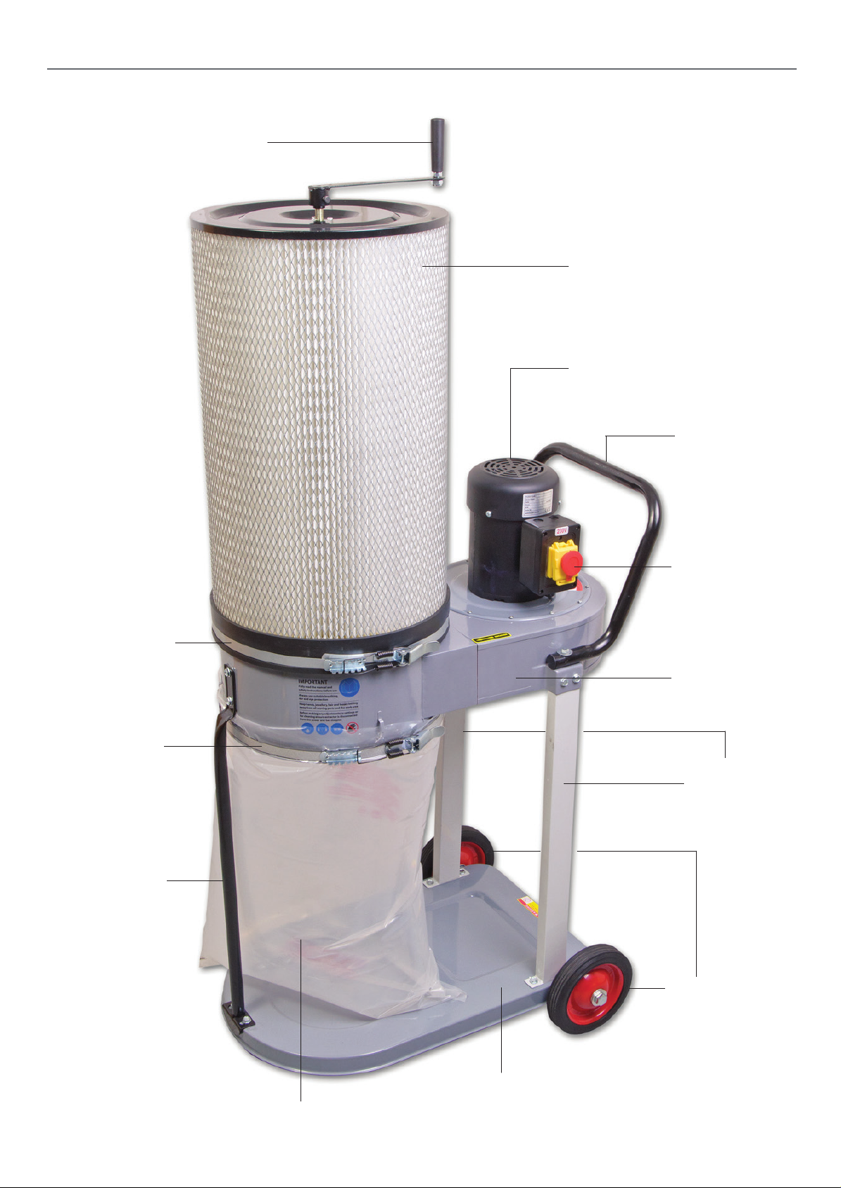
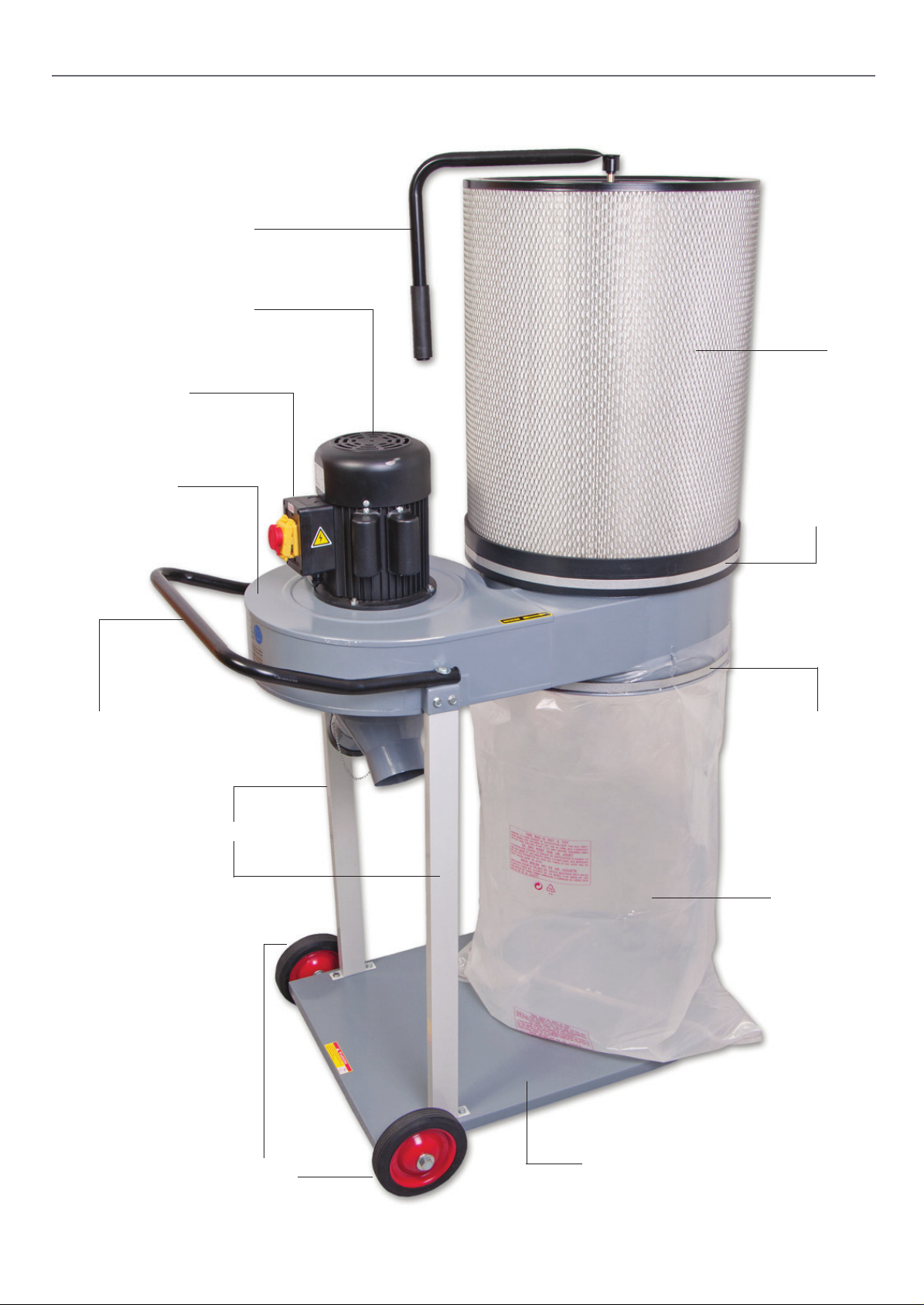
Shaker paddle operating handle
ILLUSTRATION AND PARTS DESCRIPTION
Filter
Motor assembly
Tube handle
Filter retaining belt
Bag retaining belt
Tube support bar
NVR switch
assembly
Extractor
assembly
Upright
supports
AP60E
Wheels
Base
Filter dust bag
15
Page 16
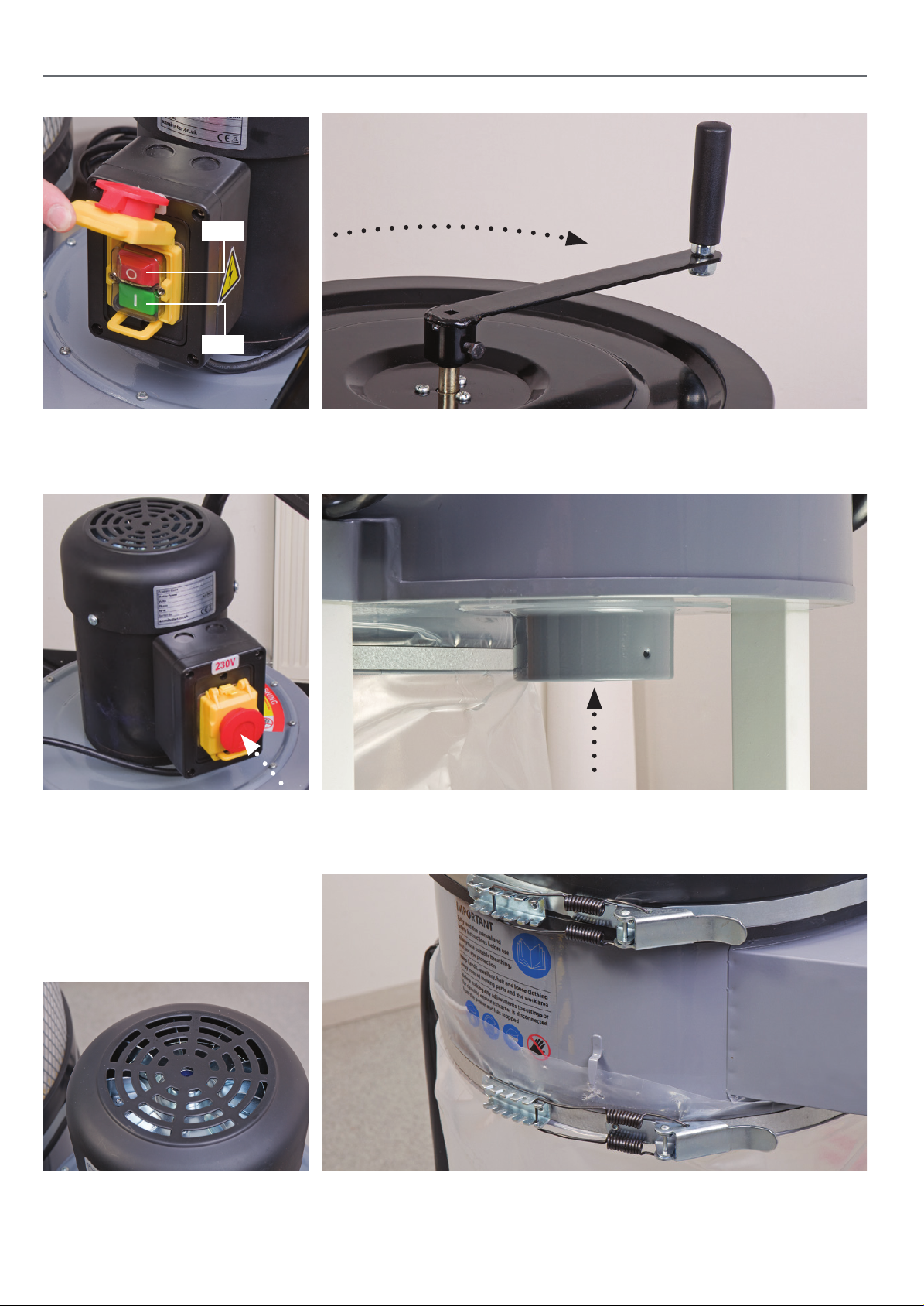
ILLUSTRATION AND PARTS DESCRIPTION
OFF
ON
NVR switch assembly with (O) indicating
(OFF) and (I) indicating (ON).
For emergencies “SLAP” the shroud
down to “STOP” the machine.
Shaker paddle assembly
Dust extraction outlet
16
Filter and dust bag and retaining steel beltsMotor vents
Page 17
Shaker paddle
operating handle
assembly
NVR switch
assembly
Extractor
assembly
ILLUSTRATION AND PARTS DESCRIPTION
Motor
Filter
Filter
retaining belt
Tube handle
Upright supports
Wheels
Bag retaining belt
Filter dust bag
Base
AP170E
17
Page 18
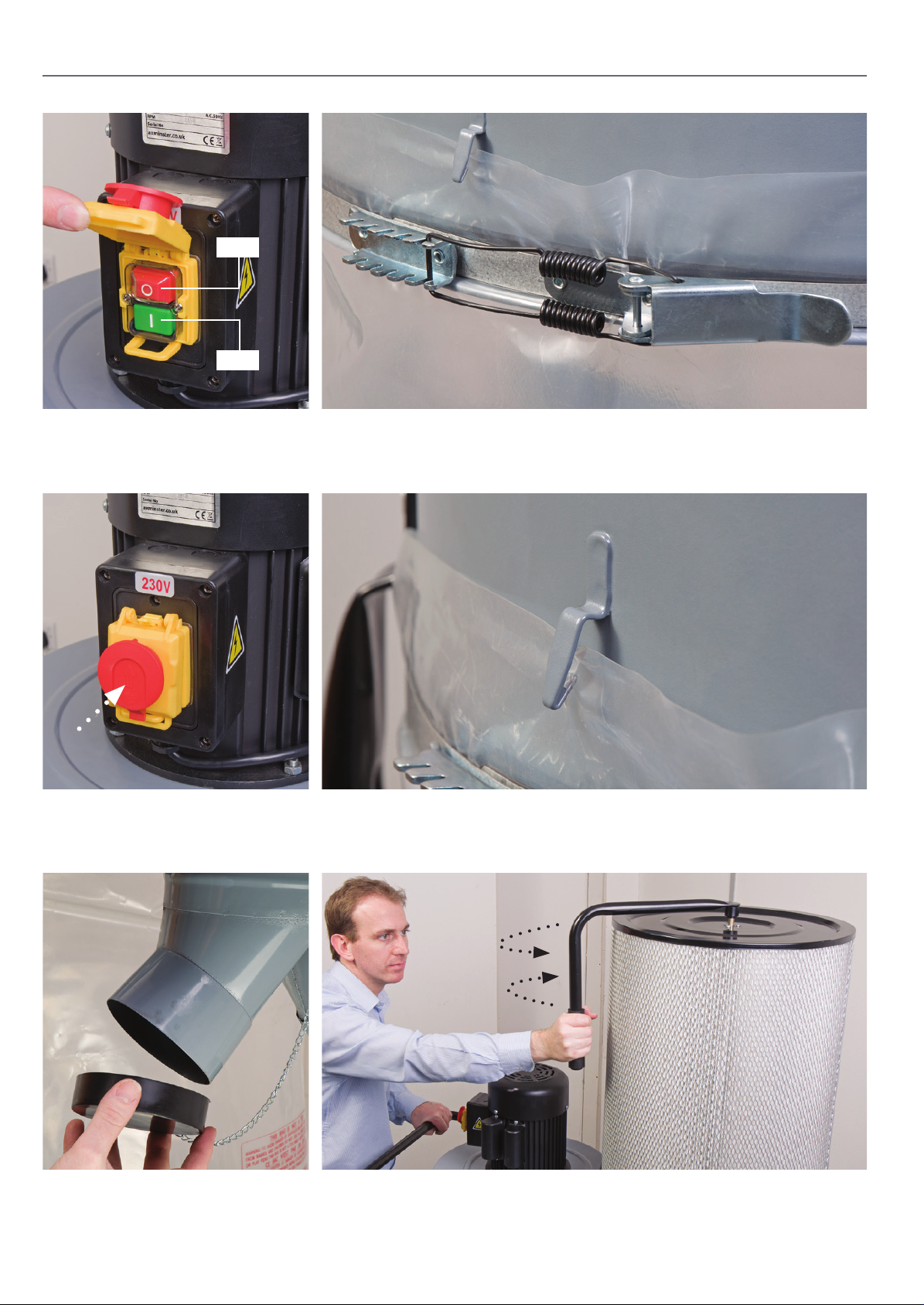
ILLUSTRATION AND PARTS DESCRIPTION
OFF
ON
NVR switch assembly with (O) indicating
(OFF) and (I) indicating (ON).
For emergencies “SLAP” the shroud
down to “STOP” the machine.
Filter bag retaining steel belt clip
Bag hook to hold the dust bag in place when fitting the retaining steel belt
Inlet moulding with lid
Shaker paddle assembly, rotate the handle to operate
the paddles with-in the filter assembly
18
Page 19
OPERATING INSTRUCTIONS
Testing the Extractor
Connect the extraction hose/s to the adaptor outlet.
WARNING!! MAKE SURE CHILDREN ARE
KEPT AWAY FROM THE EXTRACTOR WHILE IN
OPERATION.
CONNECT THE POWER SUPPLY TO THE MAINS
AND SWITCH ON!
NOTE: ALWAYS TURN ON/OFF THE EXTRACTOR
BY THE NVR CONTROL SWITCH NOT THE MAINS
SWITCH!
WAIT UNTIL IT’S UP TO FULL SPEED AND CHECK FOR
SIGNS OF VIBRATION, IF ALL IS WELL SWITCH OFF
AND WAIT UNTIL THE EXTRACTOR HAS COME TO A
COMPLETE STOP.
• Check the hoses for blockages
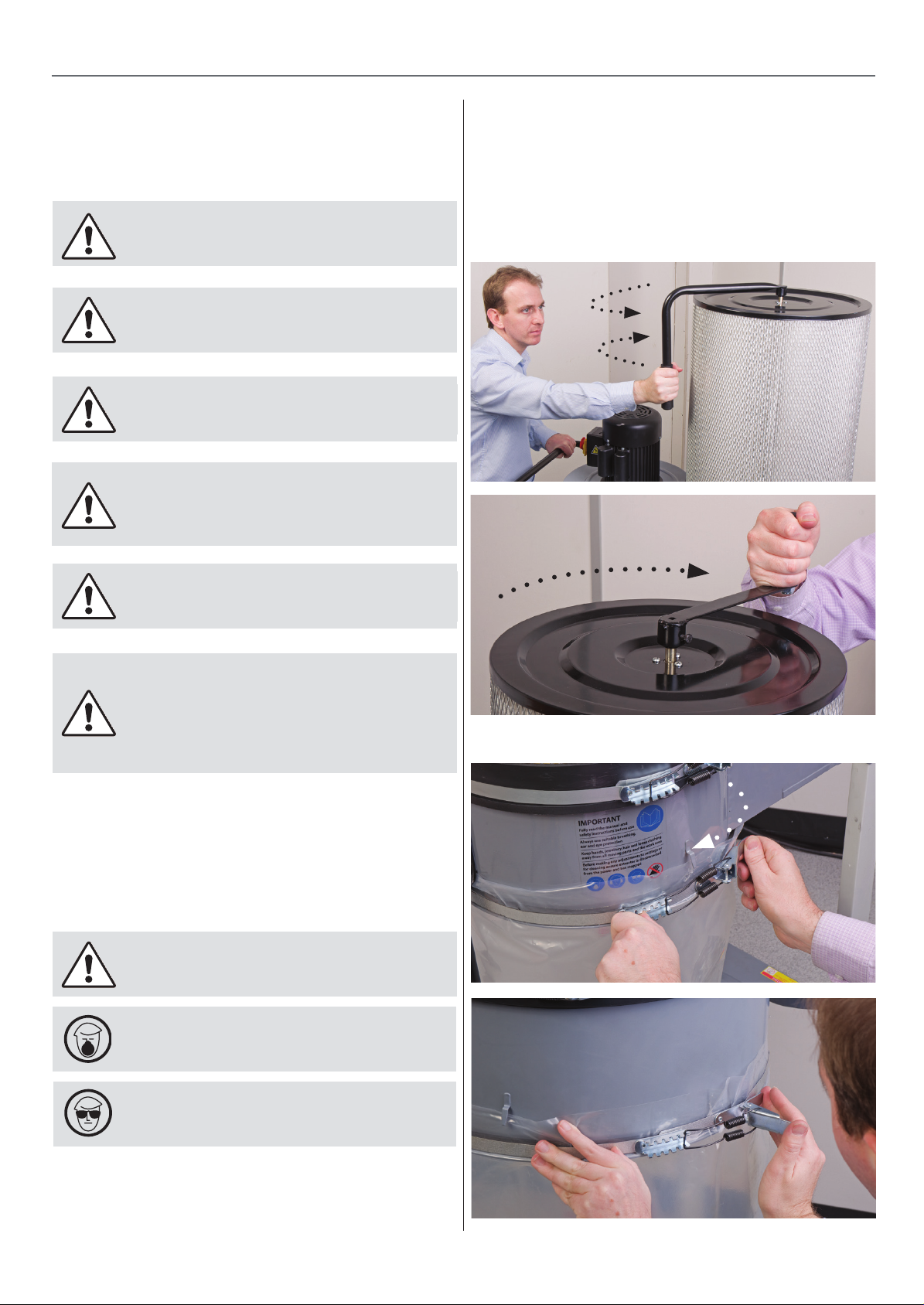
• Check the dust bag and empty if full, see fig 43-44.
Fig 41-42
DISCONNECT THE POWER SUPPLY FROM THE
MAINS!
If the extractor fails to start up or any
other strange noises apart from vibration sounds,
contact the “Technical Sales” for support.
Phone: 03332 406406
Reduced Suction Performance
After a period of time dust, sawdust and shavings can build-up
causing blockages and reduced suction performance. Carry out
the following checks to keep your extractor working at peak
performance.
DISCONNECT THE POWER SUPPLY
FROM THE MAINS!
Fig 43-44
WARNING! ALWAYS WEAR A DUST MASK
WARNING! ALWAYS WEAR EYE PROTECTION
• Check the filter for signs of buildup of sawdust and move
the shaker paddle handle back and forth to remove any
built up dust and debris from inside, see fig 41-42. Then
clean the outside with a vacuum cleaner.
19
Page 20
DUCTING SYSTEM
DUCTING SYSTEM
Gerneral Info
Many manufacturers will state the volume of air required for each machine in their manual. If
not, note the size of the extraction port and use the chart below
outlet size volume of air required
50 200 m³/hr
100 700 m³/hr
125 1100 m³/hr
150 1600 m³/hr
200 2800 m³/hr
Example: for a single machine with a 100mm port an extractor of a minimum of 700m³/hr
will be sufficient. For multiple machines count the number of extraction ports per size, multiply the number of each size by the volume of air required. Then add the results per outlet size
to give you a total volume of air required. This total is for all the machines operating at the
same time. You then must decide which and how many machines will be used at the same
time. Divide the total volume of air required by this number and add 500m³/hr. Choose an
extractor that gives the airflow required by your calculations. Look at the main inlet size of the
extractor, this is the size of the main duct to be used. In larger systems the ducting should get
larger towards the extraction unit as more machines that are in use are added to maintain the
correct air speed in the duct. This is very important; if the airflow is too low a build up of dust
and debris will occur and is a fire and explosion risk. If the air speed is high then the system
will be noisy but there will be no deposits in the ducting. Always use blastgates to close off
airflow to machines that are not in use.
MAINTENANCE
Basic design
• Keep it simple, don’t over complicate the system.
• Keep it straight, ducting runs should all be straight with as few bends as possible.
• Keep transfer duct as big as required by the extractor, this should get larger towards the
extractor.
• Keep flexible duct to a minimum. If the machine cannot be connected to the system by
solid ducting only then should flexible ducting be used for the final connection.
• Keep branches joining the duct to a maximum of 45° When branches join the main duct
ideally they must enter at the side or the top at an angle of a maximum of 45° towards the
direction of flow.
• Fit Blastgates to maximise efficiency and balance the system.
The negative pressure inside the ducting draws air into the system. Incorrect sizing of the
duct, too many bends coupled to lots of flexible hose induces losses into the system and in
badly designed systems this is akin to leaving the hand brake on in a vehicle.
Basic Maintenance
WARNING! always wear a dust mask
WARNING! Always wear eye protection
Daily
• Empty the collection bag before it overflows, wear a dust mask
whilst removing and emptying the bag.
Weekly
• Check the inlet and outlet duct and remove any accumulated
sawdust.
•Check the inlet hoses for splits and cracks, repair as necessary.
• Check the dust collection bag for wear and tear, especially
around the neck of the retaining belt. If wear
or fraying is occurring, replace the bag.
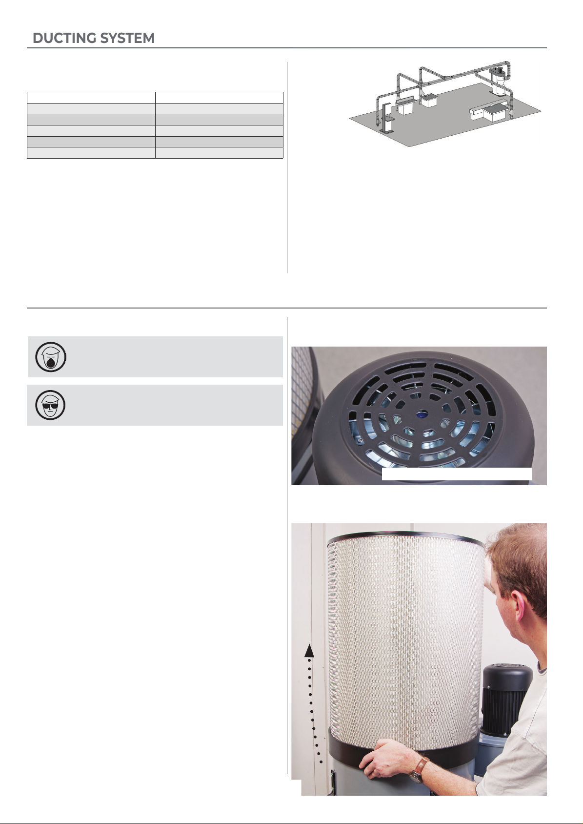
Fig 45
Clean the motor housing vents
Fig 46
• Check the motor for dust, sawdust, shavings etc, build up. If
this has occurred, clean with a vacuum cleaner, see fig 45.
• Move the shaker paddle handle back and forth to remove any
built up dust and debris from inside the filter.
Monthly
• Remove the filter securing belt and remove the filter assembly, see fig 46 using an ‘M’ class vacuum cleaner, clean inside the
filter.
20
20
Page 21

WEEKLY LEV SYSTEM MAINTENANCE LOG
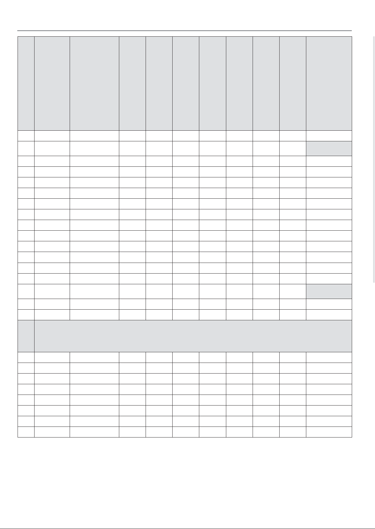
1
2
3
4
5
6
7
8
9
10
11
12
13
14
15
16
Week
Date
Checked by
Check all ducting
for physical damage
Check inlets, clear any
obstructions if found
Check operation of all
blastgate controls
Check filter(s) for damage
and condition
Check filter shakers
(if fitted) and clean filters
Check waste collector(s)
for damage and condition
Empty waste collectors
if necessary
Comments
REMOVE AND
CLEAN FILTERS
17
18
19
20
21
22
23
24
25
26
27
28
29
30
31
32
33
REMOVE AND
CLEAN FILTERS
34
21
Page 22
WEEKLY LEV SYSTEM MAINTENANCE LOG
Week
Date
35
36
37
38
39
40
41
Checked by
Check all ducting
for physical damage
Check inlets, clear any
obstructions if found
Check operation of all
blastgate controls
Check filter(s) for damage
and condition
Check filter shakers
(if fitted) and clean filters
Check waste collector(s)
for damage and condition
Empty waste collectors
if necessary
Comments
REMOVE AND
CLEAN FILTERS
42
43
44
45
46
47
48
49
50
51
52
53
54
55
56
Nearly 14 months it is now a legal requirement to have
your system tested and certified
REMOVE AND
CLEAN FILTERS
57
58
59
60
22
Page 23

LEV TESTING
Why should I bother with LEV?
The law says you must control the risks from these substances
(the Control of Substances Hazardous to Health (COSHH)
Regulations). Installing LEV may help
you to do this.
For more information about other ways of eliminating or
reducing airborne contamination at work look, at HSE’s COSHH
website, hse.gov.uk/coshh.
Health and Safety Executive
Ref Code: HSG258
The book above provides guidance on the supply of
local exhaust ventilation (LEV) equipment. It describes the
principles and good practice of deciding on, designing, commissioning and testing cost-effective LEV.
The guidance is written for the suppliers of LEV goods
and services, but will also be helpful for employers and managers in medium-sized businesses, and trade union and employee
safety representatives. All of these groups need to work to
gether to provide, maintain and use effective LEV and to reduce
exposure from inhalation of hazardous substances.
The book contains information about the roles and
legal responsibilities of suppliers and of their clients
as employers; competence; principles of good design practice
for effective LEV hoods and their classification; ducts, air movers, air cleaners; and system documentation with checking and
maintenance schedules, and the marking of defective equipment.
It also includes guidance on the specification of LEV; the
supplier’s quotation; commissioning; zone marking; the user
manual and logbook; testing and hood labels.
-
A guide to local exhaust ventilation (LEV)
Extraction Accessories
For all of our accessories please see our catalogue or visit our
website at axminstertools.com
Contact us on:
Call: 03332 406406
Web: axminstertools.com
EXTRACTION ACCESSORIES
23
Page 24
EXPLODED DIAGRAMS/PARTS LISTS
AP60E
24
Page 25

AP60E
EXPLODED DIAGRAMS/PARTS LISTS
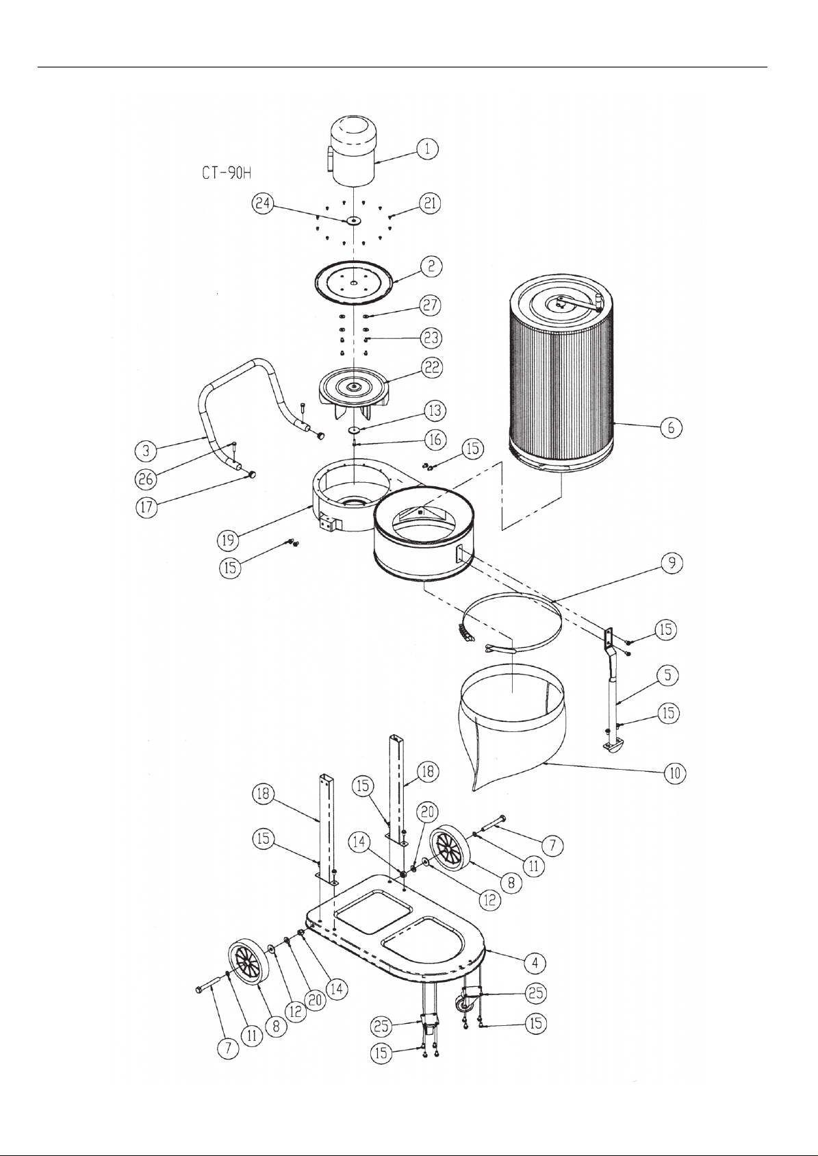
NO DESCRIPTION QTY
1 Motor 1
2 Motor Plate 1
3 Handle 1
4 Base 1
5 Collector Support 1
6 Canister Filter Unit 1
7 Hex Bolt 1/2” x 4” 2
8 Bearing Wheel 7” 2
9 Belt Clamp 1
10 Plastic Dust Bag 1
11 Washer 1/2” x 19 2
12 Washer 1/2” x 34 2
13 Impeller Washer 1
AP170E
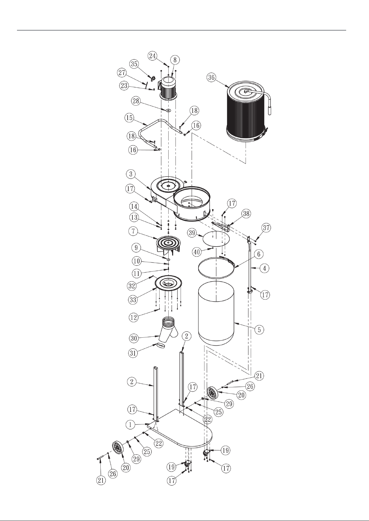
NO DESCRIPTION QTY
1 Base 1
2 Leg 2
3 Manin Housing 1
4 Collector Support 1
5 Plastic Dust Bag 1
6 Belt Clamp 1
7 Impeller 1
8 Motor 1
9 Impeller Washer 1
10 Spring Washer 1/4” 1
11 Cap Screw M6 x 30 (LH) 1
12 Round HD Screw 3/16” x 3/8” 12
13 Hex Bolt 5/16” x 1” 4
14 Washer 5/16” x18 4
15 Handle 1
16 Tube Cap 1” 2
17 Flange Bolt 5/16” x 1/2” 18
18 Hex Bolt 5/16” x 1-1/4” 2
19 Caster 2-1/2” 2
14 Lock Nut 1/2” 2
15 Hex Bolt 5/16” x 1/2” 20
16 Cap Screw M6 x 20 1
17 Tube Cap 2
18 Leg 2
19 Manin Housing 1
20 Plastic Washer 2
21 Round HD screw M5 x 10 12
22 Impeller 1
23 Hex Bolt 1/4” x 1” 4
24 Motor Packing 1
25 Caster 2-1/2” 2
26 Hex Bolt 5/16” x 1-1/4” 2
27 Washer 1/4” x 18 4
20 Bearing Wheel 7” 2
21 Hex Bolt 1/2” x 4” 2
22 Lock Nut 1/2” 2
23 Key 1
24 Flange Nut 5/16” 4
25 Plastic Washer 1/2” 2
26 Washer 1/2 “x 19 2
27 Power Cord 1
28 Motor Packing 1
29 Washer 1/2” x 34 2
30 Inlet 7” x 4” x 4” 1
31 Inlet Cap 1
32 Round HD Screw 3/16” x 3/8” 1
33 Inlet Cover 7” 1
35 Switch 1
36 Canister Filter Unit 1
37 Hex Bolt 5/16” x 3/4” 2
38 Hanging Bracket 1
39 SD2 Dust Separation Disc 1
40 Nut 5/16” 5
25
Continues Over....
Page 26
EXPLODED DIAGRAMS/PARTS LISTS
AP170E
26
Page 27
EXPLODED DIAGRAMS/PARTS LISTS
AP60E Filter Assembly AP170E Filter Assembly
27
Continues Over....
Page 28

EXPLODED DIAGRAMS/PARTS LISTS
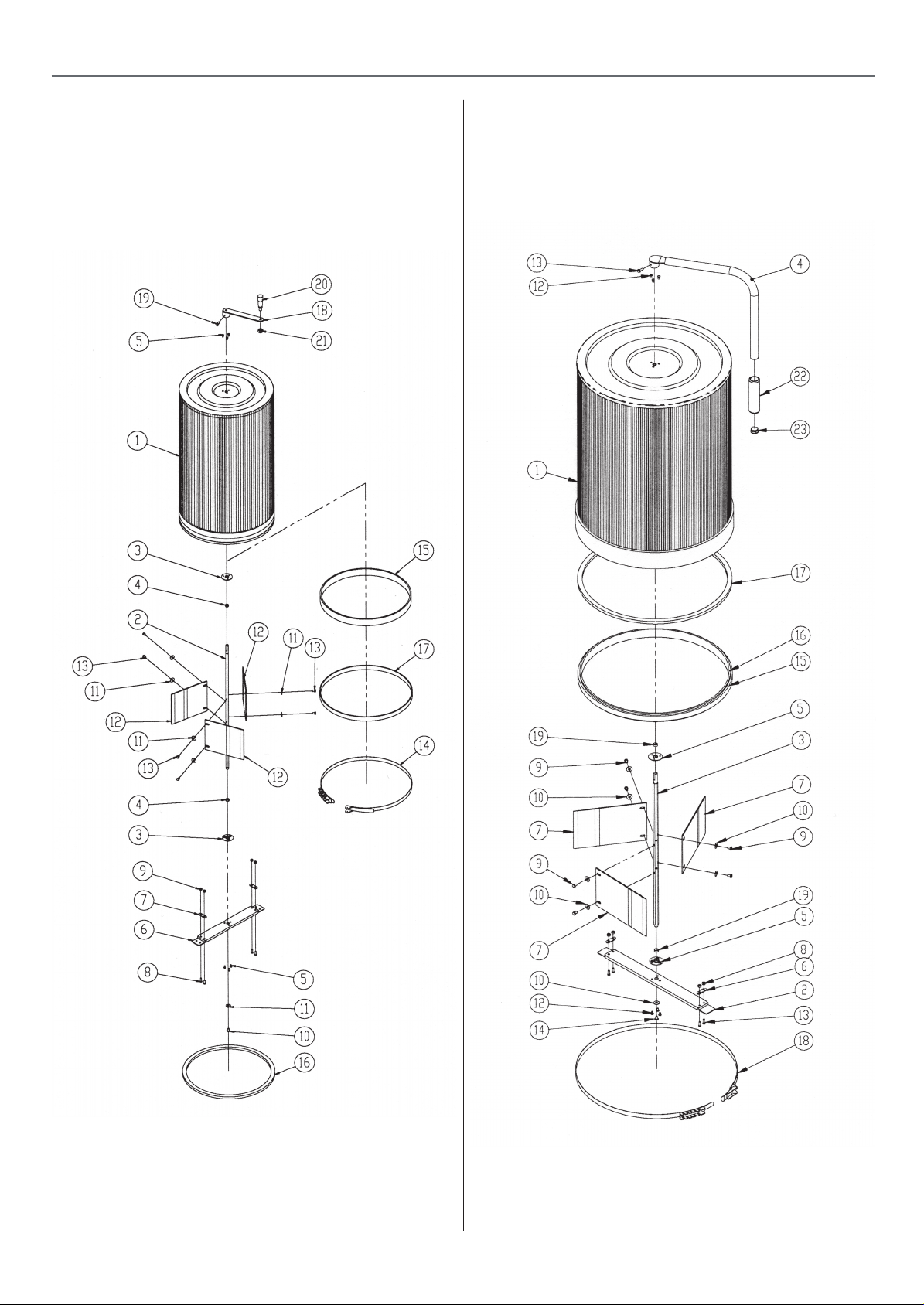
AP60E Filter Parts List
NO DESCRIPTION QTY
1 Canister Filter 1
2 Spindle 1
3 Bearing Fixing Plate 2
4 Bearing 2
5 Round HD Screw M 5 x 8 6
6 Lower Fixing Plate 1
7 Fixing Plate 2
8 Round HD Screw M 5 x 15 4
9 Nut M5 4
10 Round HD Screw M6 x10 1
AP170E Filter Parts List
NO DESCRIPTION QTY
1 Canister Filter 1
2 Lower Fixing Plate 1
3 Spindle 1
4 Handle 1
5 Bearing Fixing Plate 2
6 Fixing Plate 2
7 Flapper 3
8 Nut M5 4
9 Round HD Screw M6 x10 6
10 Washer 1/4” x 18 7
11 Washer 1/4” x 18 7
12 Flapper 3
13 Hex Bolt M6 x 10 6
14 Belt Clamp CK-370 1
15 Foam Strip 5 x 32 x 1200 1
16 Sponge 10 x 15 x 1200 1
17 Foam Strip 4 x 20 x1200 1
18 Handle Arm 1
19 Hex Bolt M6 x 16 1
20 Handle 1
21 Lock Nut M10 1
11 Round HD Screw M 5 x 15 4
12 Round HD Screw M 5 x 8 6
13 Hex Bolt M6 x 16 1
14 Hex Bolt M6 x 10 1
15 Foam Strip 4 x 20 x1560 1
16 Foam Strip 5 x 32 x 1560 1
17 Sponge 10 x 15 x 1560 1
18 Belt Clamp CK-500S 1
19 Bearing 2
20 Handle Sleeve 1
21 Tube Cap 1
28
Page 29
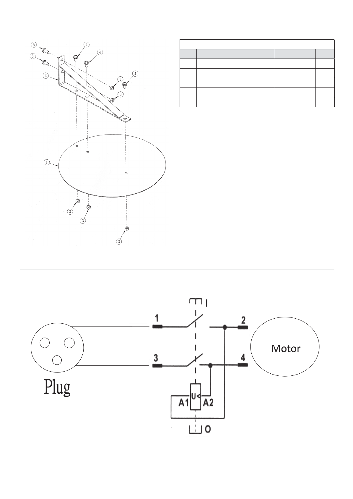
EXPLODED DIAGRAMS/PARTS LISTS
Deflector Assembly
NO DESCRIPTION PART NO QTY
1 Separator 037-0599 1
2 Separator Hanger 045-0141 1
3 5/16” Hex Nut 004-0904 5
4 5/16”x 1/2’’ Flange Bolt 004-0481 3
5 5/16”x 3/4’’ Flange Bolt 004-0483 2
WIRING DIAGRAM
29
Page 30

NOTES
30
Page 31

NOTES
31
Page 32

The packaging is suitable for recycling.
Please dispose of it in a responsible manner.
EU Countries Only
Do not dispose of electric tools together with household waste material.
By law they must be collected and recycled separately.
Axminster Tools, Axminster Devon EX13 5PH
axminstertools.com
 Loading...