

Page 1
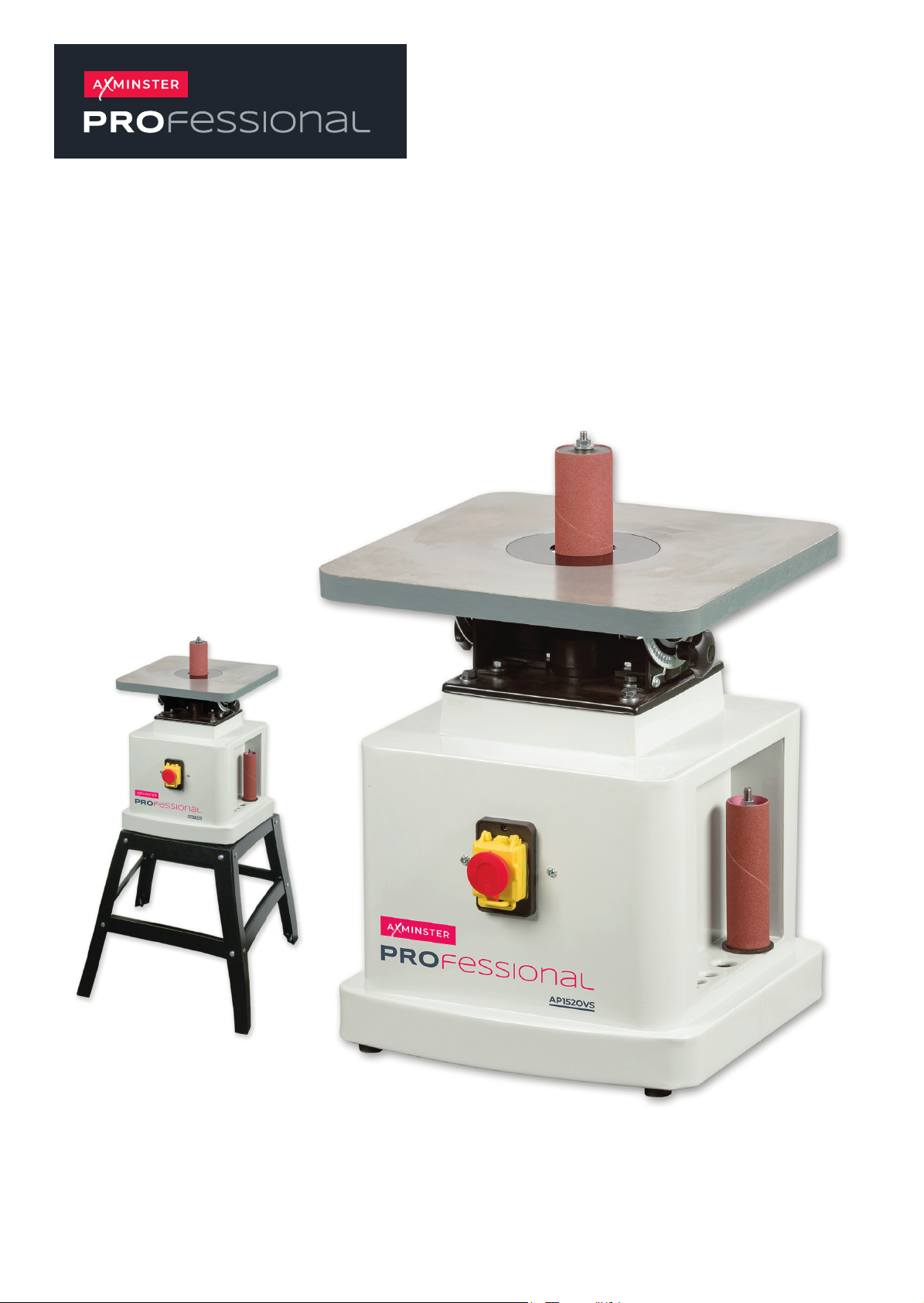
AP152OVS
Oscillating Bobbin Sander
Code 107635
Original Instructions
AT: 30/07/2025
BOOK VERSION: 05
Axminster Stand for AP150OVS
Code 106070
Page 2
Page 3

TABLE OF CONTNETS
Table of contents _____________________________________________ 1
Safety rules__________________________________________________ 2
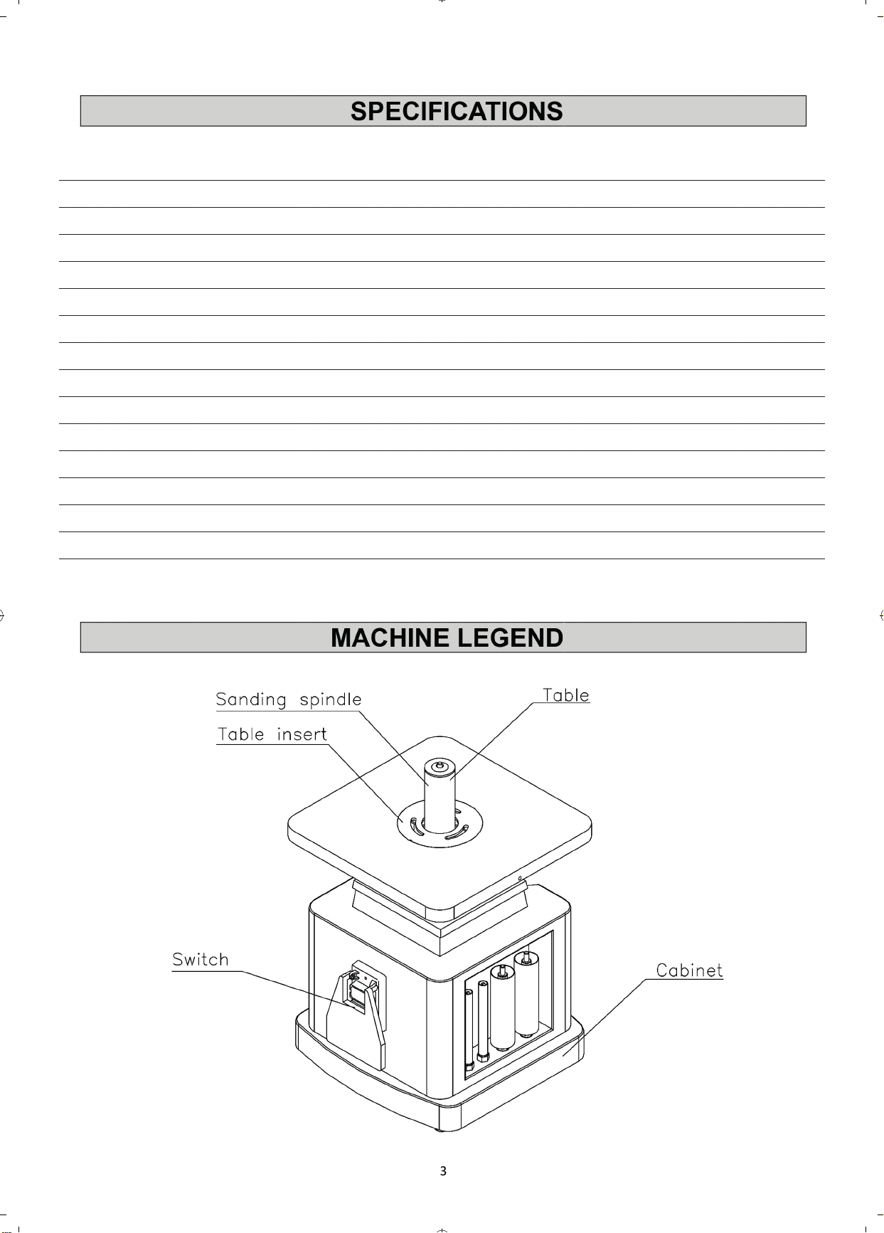
Specifications ________________________________________________ 3
Machine legend_______________________________________________ 3
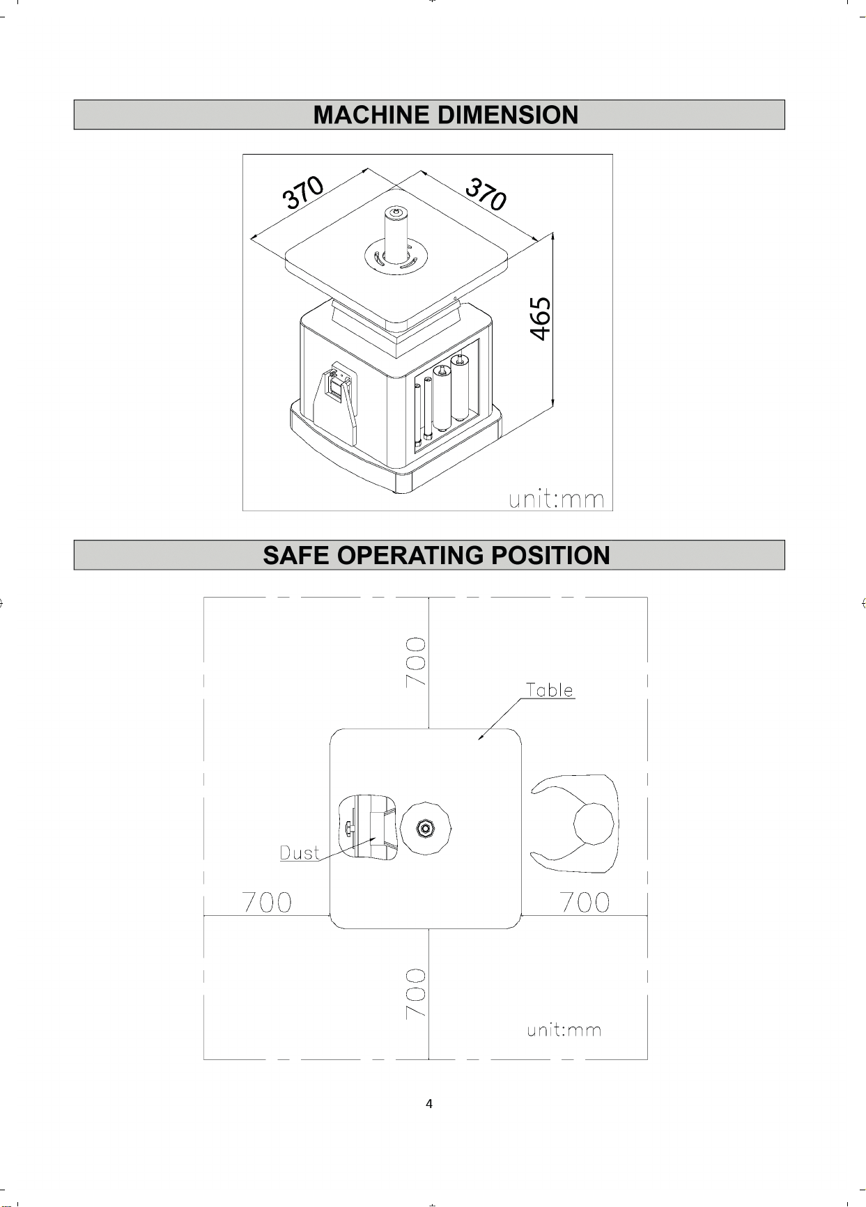
Machine dimension ___________________________________________ 4
Safe operating position ________________________________________ 4
Instructions for operations _____________________________________ 5
Tilting the table_______________________________________________ 5
Mounting spindle drum ________________________________________ 6
Selection guide for drum to table insert___________________________ 7
Maintenance of spindle sander__________________________________ 8
Troubleshooting ______________________________________________ 9
Assembly diagram ____________________________________________ 10
1
Page 4

SAFETY RULES
Read carefully before operating the machine
1. Learn the machine’s applications and limitations, as well as the specific potential hazards
particular to this machine. Follow available safety instructions and safety rules carefully.
2. Keep working area clean and be sure adequate lighting is available.
3. Do not wear loose clothing, gloves, bracelets, necklaces, or ornament. Wear face, eye, ear,
respiratory and body protection devices, as indicated for the operation or environment.
4. Keep hands well away from cutter head and all moving parts. Do not clear chips and
sawdust away with hands. Use a brush.
5. Make sure the spindles are moving at operation speed before sanding.
6. Do not push the sanding spindles to hard. The spindles will perform better and be safer
working at the rate for which it was designed.
7. Whenever possible use a dust collector with shaving hood to minimize health hazards.
8. Never leave the machine with the power on.
9. Keep children away. Make sure that visitors are kept at a safe distance from the work area.
10. Use recommended speed sanding accessory, and workpiece material.
11. Never stand on tool. Serious injury could occur if the tool is tipped or if the sanding tool is
unintentionally contacted.
12. Be sure sanding spindles are securely locked in the machine.
13. Use suitable support if stock does not have a flat surface.
14. Keep guards in place and in working order. If a guard must be removed for maintenance or
cleaning make sure it is properly attached before using the tool again.
15. Be sure that key and adjusting wrenches have been removed before turning power on.
16. Only use accessories designed for the machine. Use of accessories not recommended by
may result in a risk of injury.
17. Make sure tool is properly grounded. If tool is equipped with three-prong plug, it should be
plugged into a three-pole electrical receptacle. Never remove the third prong.
18. Always disconnect tool before servicing and when changing accessories such as spindle
sizes.
19. To make sure the cover of the magnetic switch has covered up before the machine
electrified.
20. Hold material firmly against the table.
21. Do not use this spindle sander for other than it’s intended use. If used for other purposes,
disclaims any real or implied warranty and holds itself harmless for any injury, which may
result from that use.
2
Page 5
Code 107635
Model AP152OVS
Rating Professional
Power 375W 230V 50Hz 1Ph
Spindle Speed 1,425 rpm
Drum Speed 1,500 rpm
Oscillation Per Minute 29
Stroke 24 mm
Max Cap @ 90 110 mm
Height of Bobbins 140 mm & 152 mm
Table Height 465 mm
Table Tilt 0 - 45˚
Table Size 370 x 370 mm
Dust Extraction 50 mm
Weight 30 kg
Page 6
Page 7
INSTRUCTIONS FOR OPERATIONS
1. Select spindle that is smaller than the curve to be sanded.
2. Use an insert plate that comes closest to the spindle without touching it.
3. Make sure that spindle is properly positioned in taper sleeve socket. With the wrench provided
, tighten the nut. NOTE: Never over tighten; it may be difficult to remove the spindle later.
4. When table is set at a 90° angle, sanding may be done from any corner, or location on table
around spindle.
5. When table is positioned at any angle other than 90°, it is necessary to position the work piece
over the centerline, as shown on table surface.
6. Always lock the table with the hand nut when setting at any angle, also to prevent movement
lock the tilting gear shaft.
7. Always loosen both table lock and tilting gear lock before changing the angle position of the
table. Never force the table if it does not tilt easily, reason may be that the locks are still
engaged. Never attempt to over ride the stop locks, this will cause damage to the tilting
performance.
8. A backing board is recommended when sanding thin pieces of metal or any other material. A
backing board can be easily constructed by using a piece of wood the length of the table,
pushing it into the spindle until a half circle is formed. Clamp each end of the board to the table
and proceed to sand the thin material.
9. Before leaving the machine remove any particles or pieces left over, make sure the table in
90°.
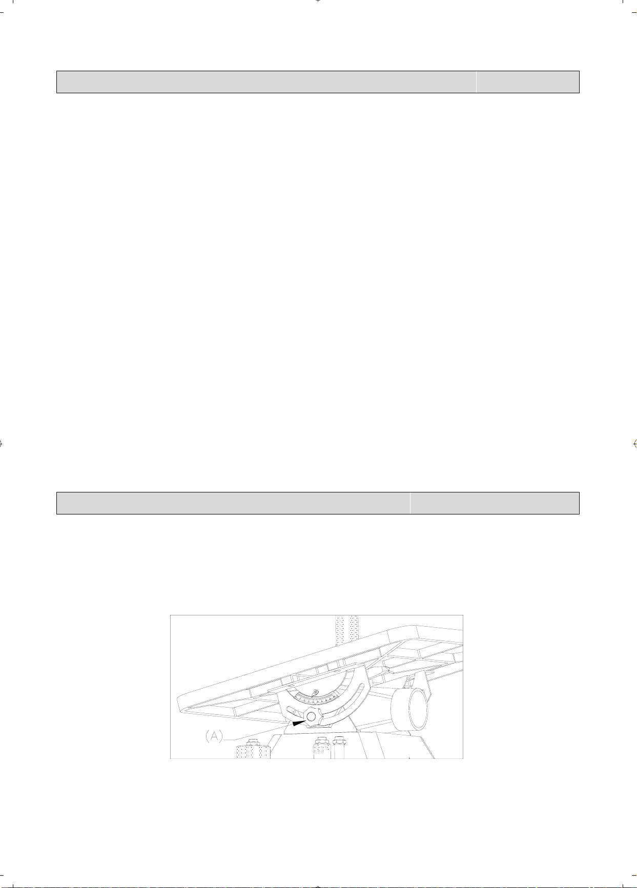
TILTING THE TABLE
1.
Loosen the two table lock knobs (A), located under the table at both sides of the machine
2. Tilt the table forward to the desired angle with your hands.
3. An angle scale is provided at the right side of the trunnion to indicate the degree of table tilt.
4. Tighten the two table lock knobs securely after the table degree has been adjusted.
5
Page 8
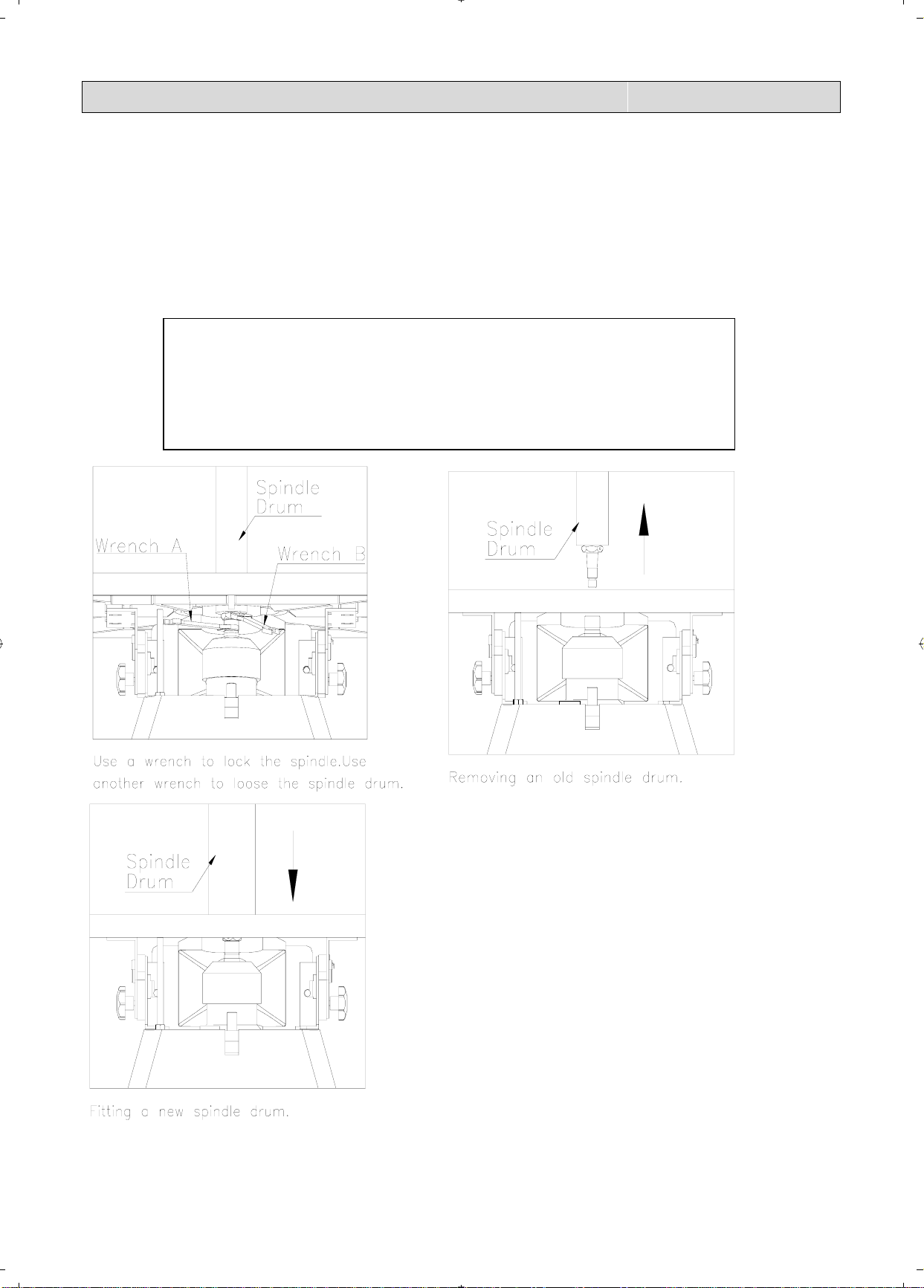
MOUNTING SPINDLE DRUM
1.
Disconnect the sander from the power source.
2. Select the proper diameter of spindle drum.
3. Clean the taper part of the spindle drum before mounting it into the spindle.
4. Use an open-end wrench to lock the spindle by holding its flat surface. At the same time, use
another open-end wrench to tighten the spindle drum.
5. Do not over tighten the spindle drum or it will be causing removable problem.
! WARNING!
Disconnect the power source before removing the drum.
△
6
Page 9
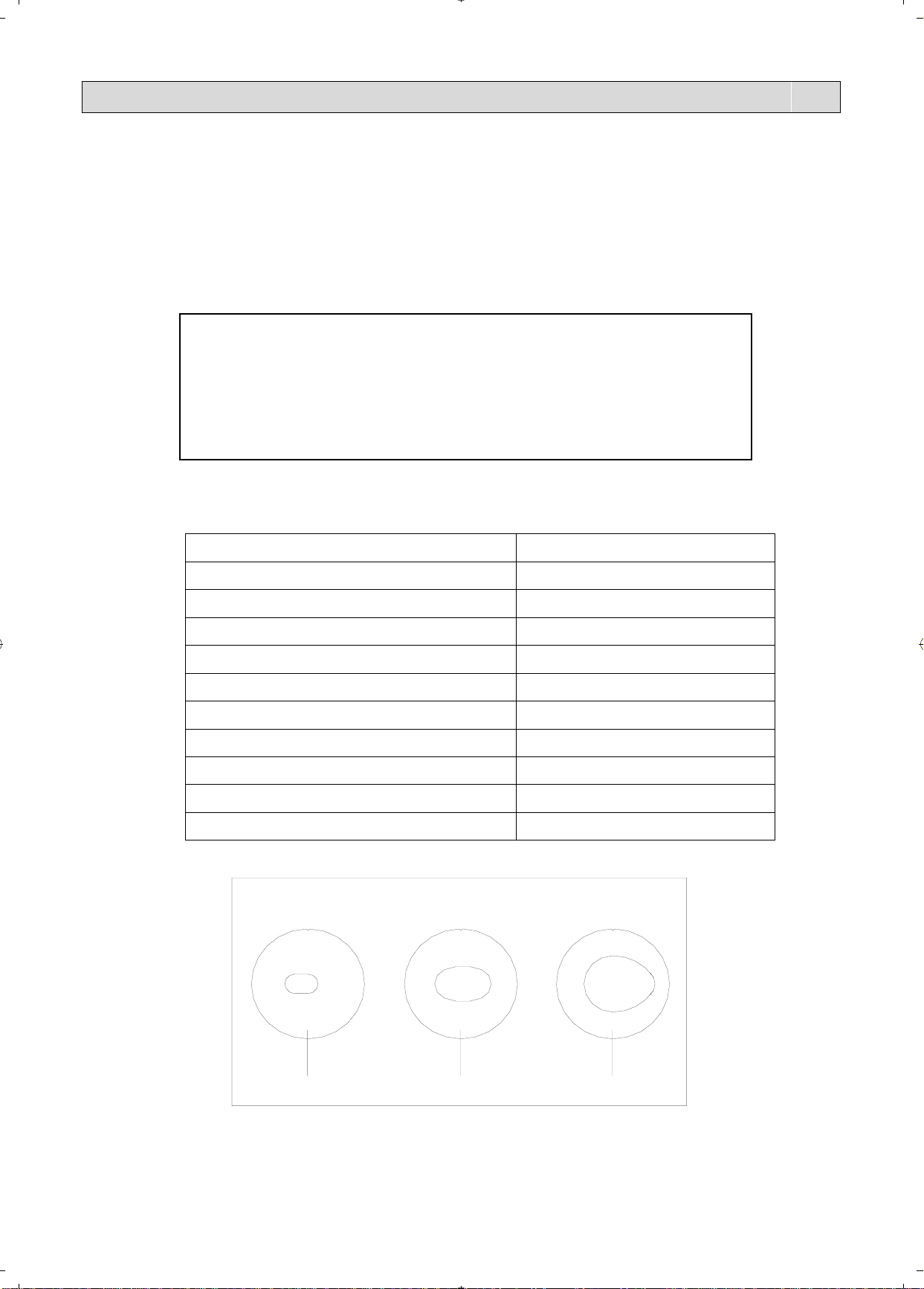
SELECTION GUIDE FOR DRUM TO TABLE INSERT
This machine is furnished with 10 drums. The range of drum diameter is from 1/4” to 4”. If the
drum diameter is changed, the table insert needs to be changed to the proper size.
The table below shows which table insert to use for various drum diameters.
! WARNING!
△
Failure to use the correct insert with the corresponding
drum may result in injury!
Drum diameter Table insert
#1 1/4” Dia. x 5” long #1
#2 3/8” Dia. x 6” long #1
#3 1/2” Dia. x 6” long #1
#4 5/8” Dia. x 6” long #1
#5 3/4” Dia. x 9” long #1
#6 1” Dia. x 9” long #2
#7 1 1/2” Dia. x 9” long #2
#8 2” Dia. x 9” long #3
#9 3” Dia. x 9” long
#10 4” Dia. x 9” long
None
None
#3#2#1
7
Page 10

MAINTENANCE OF SPINDLE SANDER
1. To keep spindle sander in perfect condition, clean machine and attachments at all times.
2. Clean tapered sleeves and tapered socket before use, this will protect spindle sleeves
from nicks.
3. Bent sleeves are easily straightened by placing them in the tapered socket and slipping a
small pipe over the steel shaft. Using a dial indicator check that it is in correct position.
4. Check gearbox for proper oil level (Approx. 1/4 up on sight glass).
5. We recommend that a small amount of grease be applied to table tilting screw once a month.
6. No lubrication is required for the bearings, they are permanently lubricated.
8
Page 11

TROUBLESHOOTING
TROUBLE CAUSES CORRECTION
Motor does not run when
power switch is turned “ON”.
Motor does not run at full
speed.
Motor does not reach full
power.
Motor overheating 1. Motor is dirty.
1. Switch is burned out.
2. Connection wire is loose
or damaged.
1. Power voltage is too low.
2. Motor is damaged.
1. Incorrect power wiring.
2. Overload.
2. Motor is damaged.
1. Replace the switch.
2. Tighten or replace the
wire.
1. Test voltage.
2. Check and repair motor.
1. Replace with the correct
size power wiring.
2. Reduce sanding load.
1. Clean motor.
2. Check and repair motor.
Excessive machine vibration Machine is incorrectly
leveled.
Mark on workpiece 1. Sanding drum is
damaged.
2. Sanding cloth on drum is
worn in some areas.
Sanding drum turns in wrong
direction
Burns on workpiece Wrong abrasive grit on
Wrong phase or voltage Make sure the phase and
sanding cloth
Adjust machine leveling
1. Replace the sanding
drum.
2. Replace sanding cloth
voltage comply with machine
requirement.
Use coarser grit to remove
more material from
workpiece.
9
Page 12
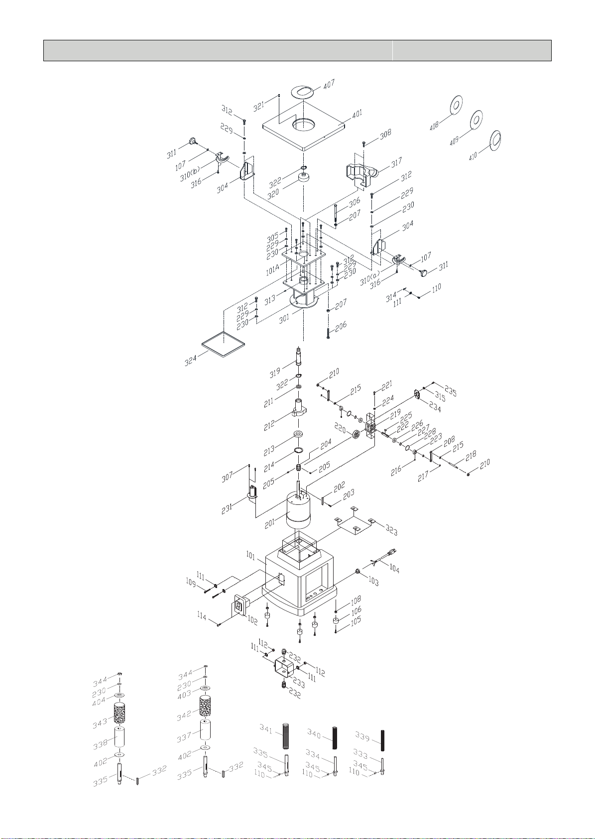
ASSEMBLY DIAGRAM
10
ASSEMBLY DIAGRAM
ASSEMBLY DRAWING
ASSEMBLY DRAWING
Page 13

Key no. Part no. DISCRIPTION Quantity
101 30201001G BASE 1
101a 30201001a TOP PLATE 1
102 W0000000 SWITCH 1
103 S1006P1 STRAIN RELIEF 1
104 L000000 POWER CORD 1
105 S0030622M PHILIPS HEAD SCREW 4
106 10107098 RUBBER FEET 4
107 S0210403 FLAT WASHER 7
108 S0011600M HEX. NUT 4
109 S00303040 PHILIPS HEAD SCREW 2
110 S0030318 PHILIPS HEAD SCREW 2
111 S0220300 GEAR WASHER 2
112 S0110300 HEX. NUT 4
114 30201002 SWITCH BOX 1
201 M000000 MOTOR 1
202 S0430650 KEY 1
203 S0040415M FLAT HEAD SCREW 1
204 30202001 WORM SHAFT 1
205 S0050610M SET SCREW 2
206 30202002 TRANSMISSION ROD 1
207 S0110800M HEX. NUT 1
208 30202003 CONNECTING ROD 2
209 S0210303 FLAT WASHER 4
210 S0120500M LOCKING NUT 2
211 C1106804 BEARING 1
212 30202004 TRANSMISSION 1
213 C1106006 BEARING 1
214 S0520059 C RING 1
215 30202005 BUSHING 4
216 S0050506M SET SCREW 2
217 S05ETW04 E RING 2
218 30202020 CONNECTING SHAFT 1
219 30202006p BRACKET 1
220 30202007p WORM 1
221 S0010615M HEX. SOCKET CAP SCREW 4
222 30202008P SHAFT 1
223 30204010 CRANK SHAFT 2
224 S0230400 SPRING WASHER 4
225 S0400415 KEY 1
226 C1106001 BEARING 2
227 S0521200 C RING 2
SPARE PARTS FOR OVS-TG
PARTS FOR AP152OVS
NO. PART NO. DESCRIPTION Q’TY
101 30201001GC BASE 1
101a 30201001a TOP PLATE 1
102 W0000018R SWITCH 1
103 S1007P-2A STRAIN RELIEF 1
104 L0000011g POWER CORD 1
105 S0030625M PHILIPS HEAD SCREW 4
106 10107098 RUBBER FEET 4
107 S0210403a FLAT WASHER 2
108 S011600M HEX. NUT 4
109 S0030318 PHILIPS HEAD SCREW 2
110 S0030508M PHILIPS HEAD SCREW 1
111 S0220300 GEAR WASHER 5
112 S0110300 HEX.NUT 2
114 S0010410M HEXAGON SOCKET SCREW M4*10 2
201 M3295111 MOTOR 1
202 S0400650 KEY 1
203 S0040415M FLAT HEAD SCREW 1
204 30202001 WORM SHAFT 1
205 S0050505M SET SCREW 2
206 30202002 TRANSMISSION ROD 1
207 S0110800M HEX. NUT 2
208 30202003 CONNECTING ROD 2
209 S0010610M HEXAGON SOCKET SCREW M6*1-10 6
210 S0120500M LOCKING NUT 2
211 C1106804KY BEARING 1
212 30202004 TRANSMISSION 1
213 C1106006 BEARING 1
214 S0530055 C RING 1
215 30202005 BUSHING 4
216 S0050406M SET SCREW 2
217 S05ETW04 E RING 2
218 30202020 CONNECTING SHAFT 1
219 30202006p BRACKET 1
Page 14
PARTS FOR AP152OVS
NO. PART NO. DESCRIPTION Q’TY
220 30202007p WORM 1
221 S0010615F HEX. SOCKET CAP SCREW 4
222 30202008P SHAFT 1
223 30204010 CRANK SHAFT 2
224 S0230400 SPRING WASHER 4
225 S0400412 KEY 1
226 C1106001 BEARING 2
227 S0520012 C RING 2
228 S0530028 C RING 2
229 S0230506 SPRING WASHER 11
230 S0210500C FLAT WASHER 13
231 30202009 OIL CAP 1
232 S100PG11E CABLE CONNECTOR 2
233 30204014 SWITCH BOX 1
234 30202014 REAR OIL CAP 1
235 S0030304 PHILIPS HEAD SCREW 2
301 30203001 HOUSING 1
304 30203003 BRACKET 2
305 S0020825M HEX. SCREW 4
306 S00208B3m SCREW M8*P1.25*120 1
307 S0010508M SCREW M5*P0.8*8 2
308 S0020816M HEX. SCREW M8*16 2
310a 40501011 SUPPORT TRUNNION (RIGHT) 1
310b 40501011a SUPPORT TRUNNION (LEFT) 1
311 30204013G TORX SCREW 2
312 S0020820M HEX. SCREW M8*20 4
313 S0050606M SET SCREW 1
314 10102022 POINTER 1
315 S0230300 SPRING WASHER 2
316 S0030510M PHILIPS HEAD SCREW 4
317 30203005 DUST COVER 1
319 30203006 MAIN SPINDLE 1
320 30203007 SWITCH COVER 1
321 S0310310 SPRING PIN 1
Page 15

PARTS FOR AP152OVS
NO. PART NO. DESCRIPTION Q’TY
322 S0520021 C RING 2
323 30202039 RUBBER PAD 4
324 30204016 EDGE BANDING STRIP 1
332 S0400550 KEY 5*5*50 2
333 30203018a 1/4" SANDING SPINDLE 1
334 30203017a 1/2" SANDING SPINDLE 1
335 30203008 5/8" SANDING SPINDLE 3
337 30203014 1-1/2" RUBBER PAD 1
338 30203015 2" RUBBER PAD 1
339 30203022 1/4" SANDING SLEEVE 1
340 30105079 1/2" SANDING SLEEVE 1
341 30105076 5/8" SANDING SLEEVE 1
342 30203013 1-1/2" SANDING SLEEVE 1
343 30203021 2" SANDING SLEEVE 1
344 S0110500L HEX. NUT 2
345 30203019b 1/4" CLAMP 3
401 30204001 TABLE 1
402 20301002 2" LOWER FOLLWER PLATE 2
403 20801002 1-1/2" UPPER FOLLOWER PLATE 1
404 20301044 2" UPPER FOLLOWER PLATE 1
406 30204017 COPPER SHEET 1
407 30204003Q 2" TABLE INSERT (OVAL) 1
408 30204004 2" TABLE INSERT (ROUND) 1
409 30204005 3/4" TABLE INSERT (ROUND) 1
410 30204006Q 3/4" TABLE INSERT (OVAL) 1
411 S0911012 WRENCH 10-12MM 1
412 S0911417 WRENCH 14-17MM 2
Page 16

The packaging is suitable for recycling.
Please dispose of it in a responsible manner.
EU Countries Only
Do not dispose of electric tools together with household waste material.
By law they must be collected and recycled separately.
Axminster Tools, Axminster Devon EX13 5PH
axminstertools.com
 Loading...