


Code 105841
Original Instructions
AC150BDS
Belt & Disc Sander
AT&M: 03/09/2019
BOOK REF : 007873

Index of Contents
EU Declaration of Conformity 02
What’s Included 03
Introduction 04
Packaging 04
General Instructions for 230V Machine 04
Specific Safety Precautions for Sanding Machines 05
Specification 05
Assembly 06-07
Set up & Adjustment 07-08-09
Illustration and Parts Description 10-11-12
Operating Instructions 13
Changing the Abrasive Belt/Disc 13-14-15-16
Maintenance 17-18
Trouble Shooting 19
Exploded Diagrams/Lists 20-21-22
Wiring Diagram 23
EU Declaration of Conformity
Cert No: MM491E
Axminster Tools & Machinery Ltd
Axminster Devon
EX13 5PH UK
axminster.co.uk
declares that the machinery described:-
Type Belt & Disc Sander
Model AC150DBS
Signed
Andrew Parkhouse
Operations Director
Da te: 28/04/2018
EU Declaration of Conformity
This machine complies with the following directives:
2006/42/EC
EN 62841-1:2015
EN ISO 12100:2010
and conforms to the machinery example for which the
EC Type-Examination Certificate No AM 50401624
has been issued by Wendeng Allwin Motors Manufacturing Co., Ltd.
at: No. 15 Sichan Road Wendeng, Shandong 264400 China (Mainland)
and complies with the relevant essential health and safety requirements.
The symbols below advise the correct safety procedures when using this machine.
Fully read manual
and safety instructions
before use
Ear protection
should be worn
Eye protection
should be worn
Dust mask
should be worn
2
HAZARD
Motor gets hot

What’s Included
Quantity Item Part Model Number
AC150BDS
1 Belt & Disc Sander A
1 Worktable B
1 Hex Key C
1 Mitre Fence D
1 Linisher Guard E
1 Instruction Manual
A
B
C
D E
NOTE: Please read the Instruction Manual prior to using your new machine; as well as the operating procedures
for your new machine, there are numerous hints and tips to help you to use the machine safely and to maintain
its efficiency and prolong its life.
Keep this instruction manual readily accessible for any others who may also be required to use the machine.
3

Introduction
A neatly designed belt and disc sander.
The worktable on the belt and disc sander is a decent size
and used on both functions. The table is easy to transfer
from one function to the other. The table pivots from 0°
to 45° and incorporates a mitre fence running in a slot for
bevel and compound angle sanding. The sanding linisher
also moves from vertical to horizontal with just two
Packaging
HAVING UNPACKED YOUR
SANDER, PLEASE DISPOSE OF
THE PACKAGING PROPERLY. THE
PACKAGING IS BIODEGRADABLE.
General Instructions for 230V Machines
The following will enable you to observe good working
practices, keep yourself and fellow workers safe and
maintain your tools and equipment in good working order.
WARNING!! KEEP TOOLS AND
EQUIPMENT OUT OF REACH OF
YOUNG CHILDREN
KEEP WORK AREA AS
UNCLUTTERED AS IS PRACTICAL.
UNDER NO CIRCUMSTANCES
SHOULD CHILDREN BE ALLOWED
IN WORK AREAS.
Mains Powered Tools
• Tools are supplied with an attached 13 Amp plug.
• Inspect the cable and plug to ensure that neither are
damaged. Repair if necessary by a suitably qualified
person.
• Do not use when or where it is liable to get wet.
Workplace
• Do not use 230V a.c. powered tools anywhere
within a site area that is flooded.
• Keep machine clean.
hexagon socket bolts to loosen with a key, suiting the task
in hand. The belt has close fitting guarding which helps this
machine achieve a high level of efficient dust extraction.
When connected to a simple vacuum extractor almost
total dust extraction is achievable. The chassis is heavily
constructed in a single iron casting to support the tables
and belt arm, and has locating holes for securing this
sander to a workbench if you so wish.
Having opened the box, remove the top packaging and lift
the machine out and place upon a clear flat surface, taking
care not to trap or pinch the power cable under the chassis.
Remove the remaining items from the box and place safely
aside.
• Leave machine unplugged until work is about to
commence.
• Always disconnect by pulling on the plug body
and not the cable.
• Carry out a final check e.g. check the cutting tool
is securely tightened in the machine and the
correct speed and function set.
• Ensure you are comfortable before you start work,
balanced, not reaching etc.
• Wear appropriate safety clothing, goggles, gloves,
masks etc. Wear ear defenders at all times.
• If you have long hair wear a hair net or helmet to prevent
it being caught up in the rotating parts of the machine.
• Consideration should be given to the removal of rings
and wristwatches.
• Consideration should also be given to non-slip
footwear etc.
• If another person is to use the machine, ensure they are
suitably qualified to use it.
• Do not use the machine if you are tired or distracted.
• Do not use this machine within the designated safety
areas of flammable liquid stores or in areas where there
may be volatile gases.
• Check cutters are correct type and size, are
undamaged and are kept clean and sharp, this will
maintain their operating performance and lessen the
loading on the machine.
• OBSERVE…. make sure you know what is
happening around you and USE YOUR COMMON SENSE.
4

Specific Safety Precautions for Sanding Machines
DO NOT sand very small pieces of work with bare hands;
try to construct some form of holder.
Make sure you are comfortable before you start work,
balanced, not reaching etc. If the work you are carrying
out is liable to generate excessive grit or dust or chips
wear the appropriate safety clothing, goggles, masks etc.
If the work operation appears to be excessively noisy wear
ear-defenders. If you wear your hair in a long style wearing
a cap, safety helmet, hairnet, even a sweatband, will
minimise the possibility of your hair being caught up in
the rotating parts of the machine. Likewise, consideration
should be given to the removal of rings and wristwatches
if these are liable to be a ‘snag’ hazard.
DO NOT work with cutting/abrasive tools of any
description if you are tired, your attention is wandering
or you are being subjected to distraction.
DO NOT use the machine within the designated safety
areas of flammable liquid stores or in areas where there
may be volatile gases.
Check that sanding surfaces are still sufficiently abrasive
to carry out the work you intend. Sanding belt cleaning
sticks are an efficient method of prolonging the life of
the belts and discs and will also maintain their operating
performance.
Check that the belts or discs are undamaged; torn edges
can pick up on the work piece and will cause the medium
to tear, often very rapidly with accompanying sharp
flapping edges.
Always offer the work piece to the belt/disc so that the
motion carries the work against the restraining surface i.e.
the work stop or the table (use the right hand side of the
disc).
DO NOT press too heavily against the sanding surface, all
this will do is slow the sander down. Remember, sanders
work by removing small particles of material quickly and
heavy pressure works adversely to the cutting process.
Further, it will accelerate the rate of ‘clogging’ of the
abrasive surfaces, rendering the machine less efficient.
If you are attempting to sand inside curves (over the
‘tracking drum’) do not press at all, other than to keep the
work piece in contact with the surface, any pressure could
upset the tracking geometry. As there is no cushioning
effect to the belt passing around the drum, expect an
added vibration and compensate for it.
Sanding of certain types of timber may make the fitting
of dust extraction mandatory in order to comply with the
directives of the HSE. However, even if it is not mandatory,
it is strongly recommended that you consider fitting dust
extraction. It will certainly reduce the level of dust and grit,
and as it helps to remove the waste quicker will certainly
prolong the longevity of the abrasive.
Above all, OBSERVE…. make sure you know what is
happening around you, and USE YOUR COMMON
SENSE.
Specification
Code 105841
Model AC150BDS
Rating Craft
Power 230V 50Hz 370W 1Ph
Belt Size 100 x 914mm
Disc Size 150mm
Table Size 216 x 146mm
Disc Table Tilt 0˚- 45˚
Dust Extraction Outlet 63mm
Overall L x W x H 470 x 370 x 295mm
500 x 250 x 650mm
Weight 21kg
5

Assembly
1
2
Loosen grub screw
3
B
Machined hole
Machined face
5
Using a square adjust the table until its perpendicular with
the sanding disc.
6
Reset the pointer to ‘ZERO’ by loosening clamping screw.
7
Remove the caphead
screws & washers
Slide the table (B) mounting bar into the machined hole
and tighten the grub screw using the supplied Hex key.
4
Clamping star knob
E
Mount the
linisher guard
assembly (E)
6

Assembly/Setup & Adjustment
8
1.6mm clearance required
Loosen
caphead
screw
The gap between the table and the disc should be set to
a maximum of 1.6mm to clear the debris and to ensure
sufficient support for the timber.
9
11
Pointer
Slide the mitre fence (D) onto the table, place a square
against the fence/disc and adjust until square. Reset the
pointer to ‘Zero’.
12
Setting Up the Linisher
The linisher can be raised to the vertical position to utilise
the worktable (B). See instruction below for setting up the
linisher.
Check the table is level and adjust by loosening the
caphead screw as shown above.
10
Square
D
1
Loosen the two clamping Hex screws holding the linisher in
the horizontal position and raise the linisher to the vertical
position.
7
Continues Over...

Setup & Adjustment
3
Tighten the two Hex
screws to secure the
linisher in position,
see step 3.
62
7
Transfer the work table (B) from the disc function mounting to the linisher’s mounting hole and secure in position.
Setup the table as described earlier, see the following
steps.
8
4
Remove the linisher guard (E) clamping Hex screws and
place the guard safely to one side. Replace the two Hex
screws/washers to the side of the linisher.
5
9
1.6mm clearance required
10
8

Setup & Adjustment
Tracking the Linisher Belt
The tracking control works as follows:-
Using your hand, roll the belt towards the drive drum, check
that the belt stays in the middle of the table, if not, adjust
the track control slightly, and move the belt again, continue
until the belt runs down the centre of the linisher’s table
DO NOT make large adjustments,
and remember the belt may take
time to react to your alteration.
Little by little is a good maxim
to observe when carrying out
tracking operations.
1
Tracking
wheel
2
4
Turn the tracking wheel away from you to manoeuvre the belt
to the right.
5
Belt tracking down the centre of the linisher
6
3
Turn the tracking wheel towards you to manoeuvre the belt to
the left.
9

Illustration and Parts Description
Linisher guard
63mm dust
extraction outlet
Belt tensioning lever
Linisher abrasive belt
Belt tracking wheel
Sanding disc
NVR ON/OFF
control switch
Worktable
Mitre fence
Worktable tilt assembly
Clamping star knob
C
A
B
A
B
Worktable tilt scale (A) and pointer (B) Mitre fence pointer (A), scale (B) and clamping knob (C)
10

Linisher’s stop/ levelling bolt
Illustration and Parts Description
Work bench
mounting hole
Mitre fence and Hex key storage holders Clamping Hex bolts, access holes for linisher assembly
Drive belt cover
11

Illustration and Parts Description
NVR ON/OFF control switch Drive belt tensioning grub
Linisher guard/Workstop, can be used as a work support
when the linisher is in the vertical position
63mm dust extraction outlet
screw and locking nut
Worktable adjusting Hex bolt
Three function positions
A
Linisher function with worktable
Linisher function, utilising the
linisher’s guard as a work support
12
B
Disc function (A) set at 90˚ degrees
Disc function (B) set at 45˚ degrees

Operating Instructions/ Changing the Abrasive Belt/Disc
Sanding Disc
MAKE SURE THE SANDER IS ON A
FLAT LEVEL SURFACE.
NOTE: GO ROUND AND MAKE SURE
EVERYTHING IS SECURE, FASTENED
DOWN, THAT ALL TOOLS ARE
CLEARED AWAY FROM THE WORK
AREA!
WARNING!! KEEP TOOLS AND
EQUIPMENT OUT OF REACH OF
YOUNG CHILDREN
CONNECT A DUST EXTRACTION
MACHINE TO THE SANDER.
ALWAYS WEAR EAR DEFENDERS,
EYE PROTECTION AND DUST MASK.
CONNECT THE SANDER TO THE
MAINS SUPPLY!
DISCONNECT THE SANDER FROM
THE MAINS SUPPLY BEFORE
CONTINUING!
1
B
Remove the worktable (B) and place safely aside.
2
Remove the two screws holding the extraction plate and
place to one side.
63mm
Connect your extraction hose to the sander’s outlet.
Give the machine a ‘quick’ burst check ( i.e. quick ON-OFF)
to ensure everything is O.K. If everything is satisfactory, the
Sander is ready for use.
13
3
WEAR A DUST MASK &
EYE PROTECTION WHEN
CHANGING THE DISC!
Continues Over...
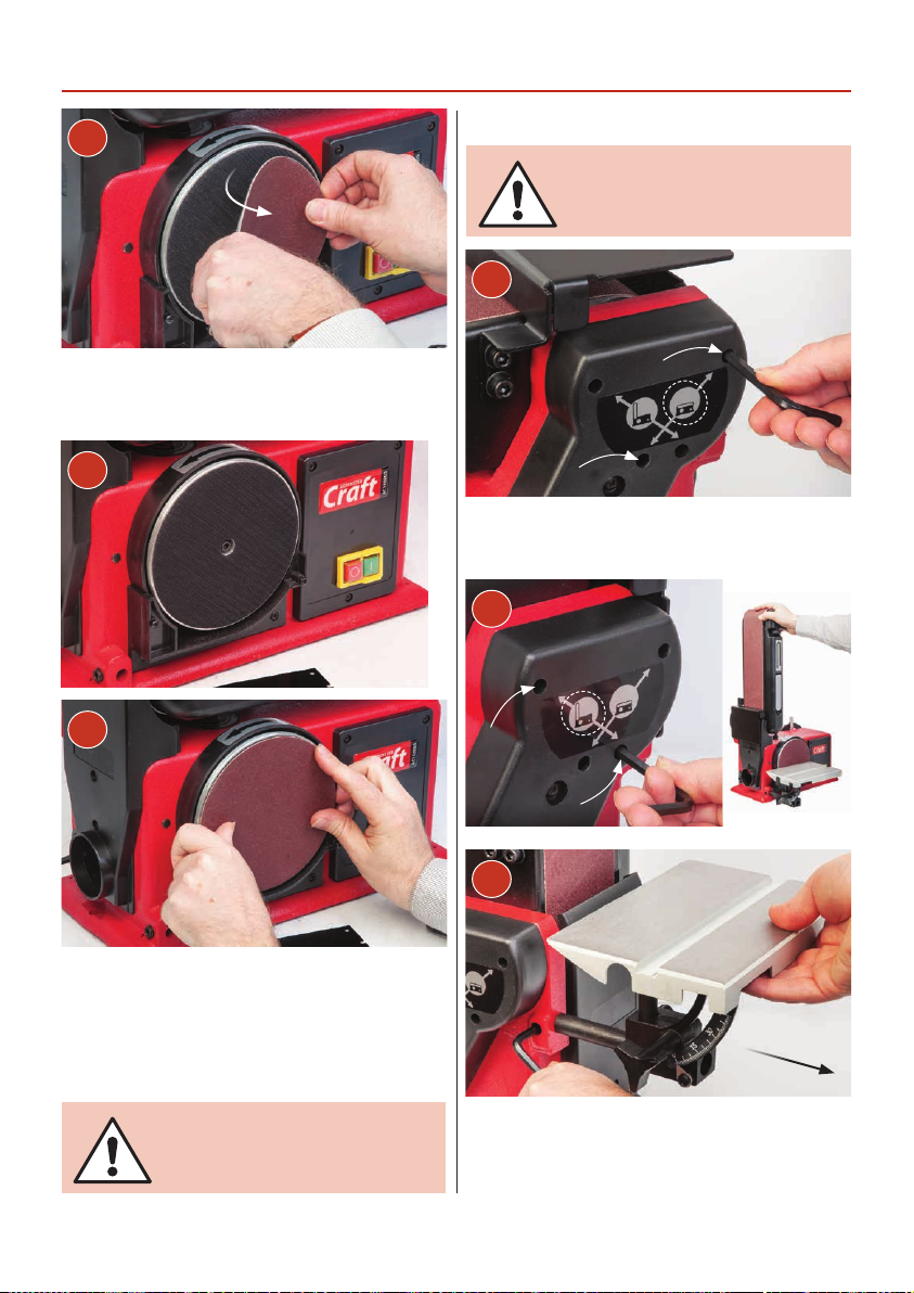
Changing the Abrasive Belt/Disc
4
The abrasive disc is attached to the sander’s face by Velcro,
a strip of fabric that clings when pressed together. Simply
peel off the old abrasive disc. Clean the surface of the disc.
5
Linisher Belt
DISCONNECT THE SANDER FROM
THE MAINS SUPPLY BEFORE
CONTINUING!
1
Loosen the two clamping Hex screws holding the linisher
and raise to the vertical position. Tighten the Hex screws.
2
6
Line up the new abrasive disc with the face of sanding disc
and using a piece of cloth in your hand or wear a glove, to
firmly press the abrasive to the disc plate, the application
will be reinforced by a gentle sanding action across the
face when you first use the new sanding disc. Re-assemble
the sander.
CONNECT THE SANDER TO THE
MAINS SUPPLY AND CONTINUE
WITH OPERATION.
3
Remove the worktable (B) if installed for easy access and
place to one side.
14

Changing the Abrasive Belt/Disc
4
Loosen the two screws holding the rear guard.
5
7
WEAR A DUST MASK &
EYE PROTECTION WHEN
CHANGING THE BELT!
Lift and remove the rear guard, place to one side.
6
Release the belt tension by lifting up the tensioning lever.
Remove the linisher belt. Inspect the new belt, ensure that
there are no tears or rips especially along the edges, check
the direction arrows on the inner surface of the belt and fit
accordingly. The direction of the arrows should point to the
drive drum of the sander.
NOTE: If you are using an old belt, and the arrow
markings have worn off, check the direction of travel,
see diagram below.
Belt overlay
NOTE: Before sliding on the new belt check there is no
dust or resin build up on the drums or at the edges of
the linisher, clean in and around the extraction ports
for dust or resin build up, see next page.
15
Belt underlay
Glue joint
Continues Over...

Changing the Abrasive Belt/Disc
8
9
Remove the two screws holding the side extraction panel
and check for signs of build up of dust and debris. Clean
and replace the panel. Also clean the inside of the linisher.
10
Idler drum
11
Slide the belt over the drums, making sure the arrows on
the belt are pointing down towards the drive drum. Centre
the belt and lower the tension lever to re-tension the
linisher belt. Replace the rear guard.
Drive drum
12
CLEAR ALL TOOLS AWAY FROM
THE WORK AREA. CONNECT THE
SANDER TO THE MAINS SUPPLY!
Give the machine a ‘quick’ burst check ( i.e. quick ON-OFF)
to ensure everything is O.K. If everything is satisfactory,
continue with operation.
16

Maintenance
DISCONNECT THE SANDER FROM
THE MAINS SUPPLY BEFORE
CONTINUING!
WEAR A DUST MASK &
EYE PROTECTION WHEN
CLEANING YOUR SANDER!
There is very little mechanical maintenance that can be
carried out on the machine. Most prudent maintenance
is preventative and concerned with keeping the machine
clean.
At reasonable intervals, inspect and remove all dust/resin
build up using a class ‘M’ vacuum cleaner.
Remove the worktable (B),side extraction panel/disc
extraction plate and clean any dust or resin build up.
Inspect the sanding disc for signs of wear and tear and
replace if necessarily. Re-assemble the sander.
1
B
3
E
4
Remove the linisher’s guard (E) or worktable (B) and clean
any dust or resin build up, inspect the sanding belt for signs
of wear and tear and replace if necessary. Re-assemble the
sander.
Linisher Drive Belt Tension
If you notice the belt stopping while under load and the
disc is still in motion this could mean a sign that the belt is
damaged or has become loose. To check, remove the drive
belt cover and examine the belt for signs of fraying and
missing teeth.
17
1
Continues Over...
2

Maintenance
2
1-2mm
Depression
Check the belt tension, if required adjust the drive belt
tensioning grub screw and locking nut using the Hex key
(C) and spanner, see image (4-5).
Turn the grub screw clockwise (+) to push the motor down
or anti-clockwise (-) to decrease the tension.
DON’T OVER TENSION THE BELT
WHICH CAN CAUSE THE MOTOR
TO OVERLOAD!
4
Grub screw
Lock nut
53
When complete replace the drive belt cover. Clear tools
away from work area and connect the sander to the mains
supply. Switch on, a gentle sanding action across the face
of the belt will check if enough tension has been applied.
Disconnect the sander from the mains supply.
18

Trouble Shooting
PROBLEM POSSIBLE CAUSE REMEDY
1. Defective or broken
“ON -OFF” switch
2. Defective or damaged
switch cord
1-3. Replace all broken or defective parts
before using the sander. Contact us on 0800 371822
Motor will not run
Machine slows down
while sanding
Wood burns
while sanding
3. Defective or damaged
switch relay
4. Burned out motor
5. Blown fuse
1. Applying too much pressure
to workpiece
1. Sanding disc/belt is worn
2. Excessive pressure being
applied to workpiece
4. Contact us on 0800 371822
Customer service enquires cs@axminster.co.uk
Servicing, parts & technical support
specialist.aftersales@axminster.co.uk
1. Apply less pressure to sanding surface
1. Replace the disc/belt
2. Reduce pressure being
applied to workpiece
19

Exploded Diagrams/Lists
20

Exploded Diagrams/Lists
No Specification Qty
1 Philips screw M5 x 35 2
2 Belt guard 1
3 Hex screw M8 x 35 2
4 Big flat washer M4 x 8 3
5 Screw M12 x 10 2
6 Hex screw M12 x 30 1
7 Hex nut M12 2
8 Spring washer φ12 1
9 Sleeve 1
10 Base 1
11 Capacitor 100uF/250V 1
12 Capacitor clamp 1
13 Spring washer ϕ4 5
14 Phillips screw M6 x 8 3
15 Idler pulley 1
16 Relay 1
17 Screw ST2.9 x 30 1
18 Wire connection box 1
19 Cord clip 1
20 Plug and cord 1
21 Protect plate 1
22 Screw ST4.2 x 10 2
23 Switch KJD20-2 1
24 Belt paper 1
25 Bearing 6001 4
26 Idler roller 1
27 Retainer ring φ12 2
28 Sleeve 2
29 Idler shaft 1
30 Adjustment spring 1
31 Rubber washer 1
32 Flat washer φ6 3
33 Adjustment knob 1
34 Phillips screw +spring
washer
M5 x 25 3
35 Joint lever 1
36 Spring 1
37 Support 1
38 Support cover 1
39 Philips screw M5 x 25 2
40 Pin 5 x 10 1
41 Tension knob 1
42 Sleeve 1
43 Pin 1.6 x 10 1
44 Tension pole 1
45 Phillips screw +tooth
washer+big flat washer
46 Spring washer
47 Philips screw M5X8 3
48 Bearing cap 1
49 Philips screw+flat
washer
50 Hex screw M12 x 20 1
51 Retainer φ6 2
52 Retainer washer M5 2
53 Bolt M4 x 20 2
54 Limiting plate 1
55 Hex screw+flat washer M8 x 16 2
56 Hex screw M8 x 16 1
57 Driving roller 1
58 Philips screw+lock
washer
59 Bearing base 1
60 Retainer M5 x 20 3
61 Philips screw M10 x 16 1
62 Flat washer φ5 1
63 Table 1
64 Mitre gauge 1
65 Spring washer φ5 1
66 Philips Screw M5 x 10 1
67 Support rod 1
68 Table damping set 1
M5 x 16 1
φ6
M5 x 10 5
M5 x 16 left 2
4
21

Exploded Diagrams/Lists
69 Hex nut M5 1
70 Knob 1
71 Hex nut M6 1
72 Table pointer 1
73 Table support rod 1
74 Connect block 1
75 Belt 1
76 Motor arbor wheel 1
77 Hex bolt M6 x 122 4
78 Motor rod 1
79 End cap 2
80 Bearing 6203 2
81 Rotor 1
82 Stator 1
83 Cord sleeve 1
84 Hex nut 4
85 Wheel box 1
86 Philips screw 1
87 Philips screw 6
88 Disc cover 1
89 Hex screw M6 x 16 1
90 Tooth washer M6 x 16 1
91 Disc 1
92 Rubber foot 5
93 Dust hood 1
94 Wave washer φ40 1
95 Mitre gauge knob 1
96 Mitre gauge pointer 1
97 Wire connection box
cover
98 Mitre gauge 1
99 Protect plate 1
100 Mitre gauge rod 1
101 Disc hook 1
102 Disc paper 1
103 Wrench clip 1
104 Mitre gauge clip 1
105 Philips screw 4
106 Hex nut M4 1
107 Philips screw M4 x 12 1
108 Base plate 1
109 Motor support 1
110 Philips screw+spring
washer+flat washer
111 Hex wrench M6 x 90 x 32 1
112 Dust plate 1
113 Philips screw+spring
washer+flat washer
114 Philips screw M5 x 16 5
M5 x 8 1
M5 x 10 2
1
22

Wiring Diagram
23

The Axminster guarantee is available on
Craft, Trade, Engineer, Air Tools & CNC Technology Series machines
Buy with confidence from Axminster!
So sure are we of the quality, we cover all parts and labour free of charge for three years!
For more information visit axminster.co.uk/3years
The packaging is suitable for recycling.
Please dispose of it in a responsible manner.
EU Countries Only
Do not dispose of electric tools together with household waste material.
By law they must be collected and recycled separately.
Axminster Tools & Machinery
Axminster Devon EX13 5PH
axminster.co.uk
 Loading...