

Page 1
700253
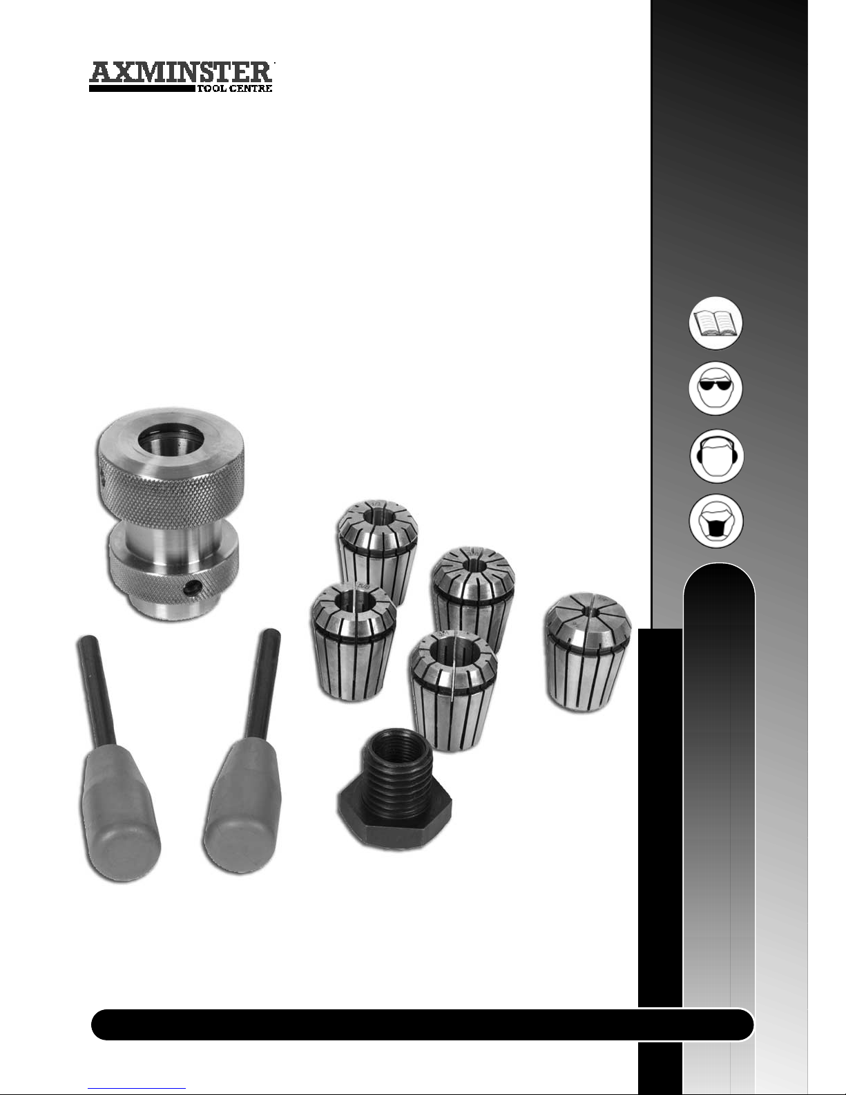
Collet Chuck
System Set
User Manual
www.axminster.co.uk
Page 2
Index of Contents...................................................................................................................02
What’s in the Box………….………........……..…………......................................................... 03
General Operating Instructions..............................................................................04
Operating Illustrations..................................................................................05-06-07
Index of Contents...
Page No.
Safety Protection Symbols
SAFETY!!
!
The symbols shown on the cover of this
manual advise that you wear the correct
safety protection when using this machine.
E
y
e
P
r
o
t
e
c
t
i
o
n
S
a
f
e
t
y
H
e
l
m
e
t
P
r
o
t
e
c
t
i
v
e
G
l
o
v
e
s
S
a
f
e
t
y
F
o
o
t
w
e
a
r
R
e
s
p
i
r
a
t
o
r
S
a
f
e
t
y
V
i
s
o
r
R
e
a
d
M
a
n
u
a
l
T
w
o
M
a
n
A
s
s
e
m
b
l
y
E
a
r
D
e
f
e
n
d
e
r
s
D
u
s
t
M
a
s
k
02
WARNING!!
!
KEEP TOOLS AND EQUIPMENT OUT
OF THE REACH OF YOUNG CHILDREN.
UNDER NO CIRCUMSTANCES SHOULD CHILDREN BE
ALLOWED IN WORK AREAS.
!
KEEP WORK AREA WELL LIT.
!
Page 3
03
What’s in the Box...
FREEPHONE 0800 371822
Model Number: 700253
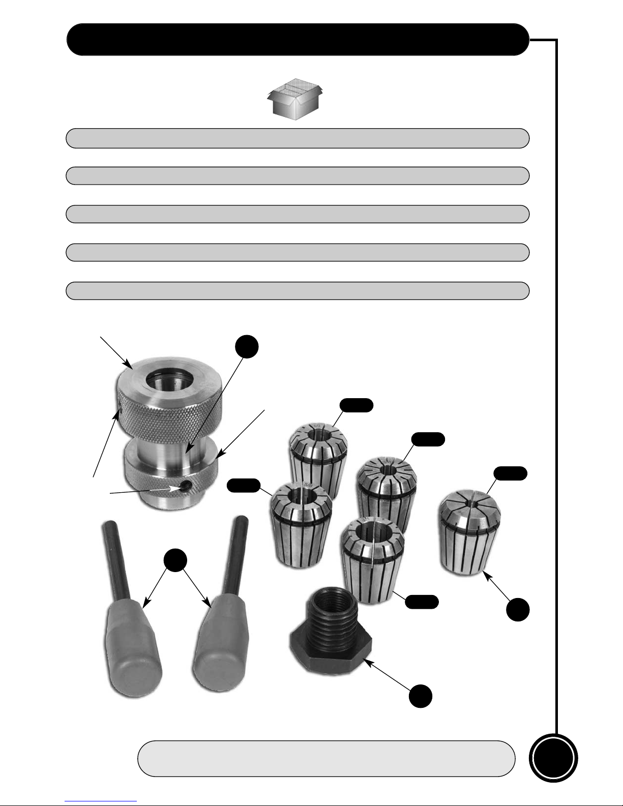
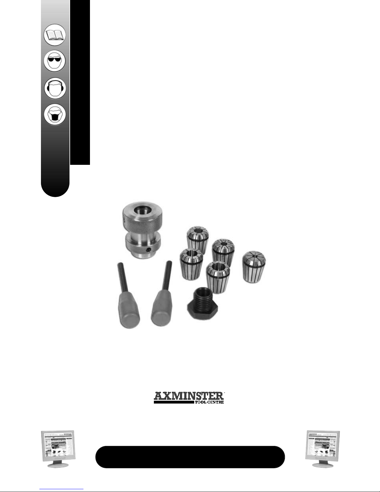
1 off Heavy-Duty Collet Closing Head
(Pre-threaded for 25.4mm x 8tpi)
5 off Industrial Collet Grip
(6mm, 10mm, 12mm, 16mm and 20mm)
2 off Tommy Bar
1 off Lathe Adapter (19mm x 16tpi)
1 off Instruction Manual
A
B
C
D
A
B
C
D
6mm
10mm
12mm
16mm
20mm
Sleeve nut
Chuck body
Blind
pockets
Page 4
04
General Operating Instructions...
www.axminster.co.uk
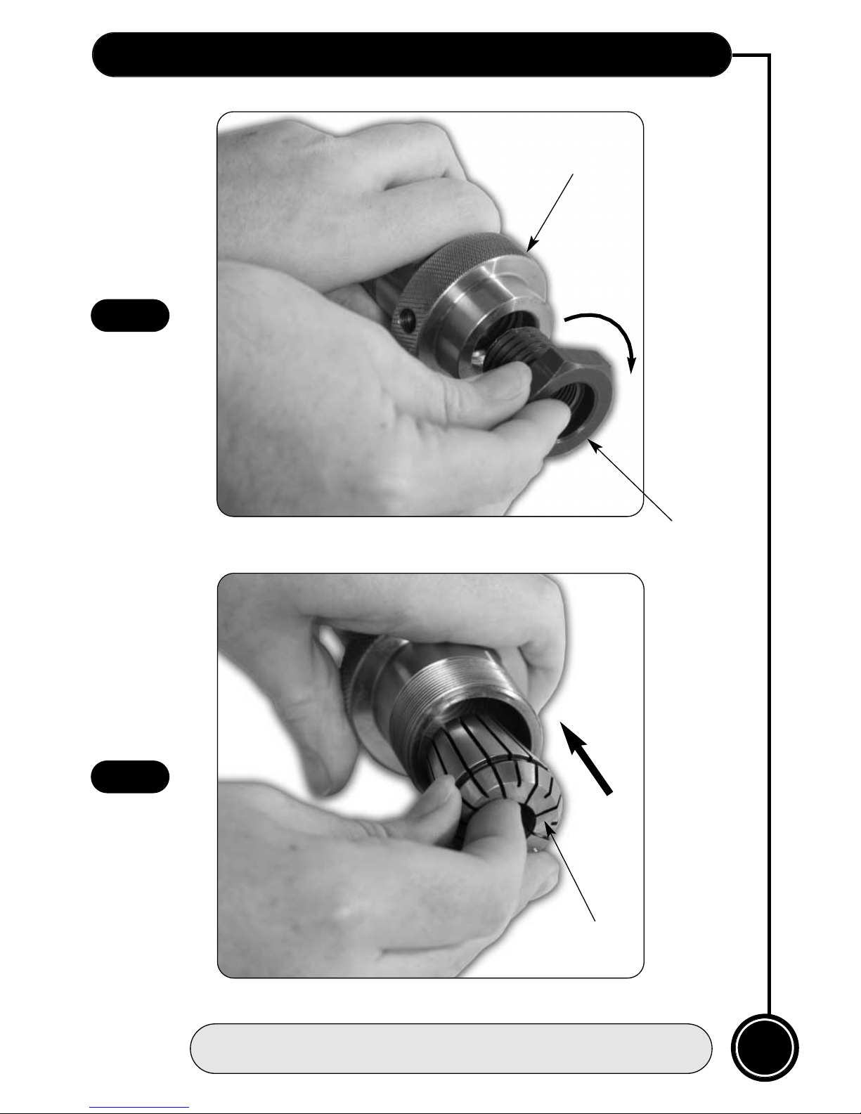
1. Thread the lathe adapter into the body of the chuck if required. (See fig 1)
2. Thread the chuck body on to the headstock of the lathe.
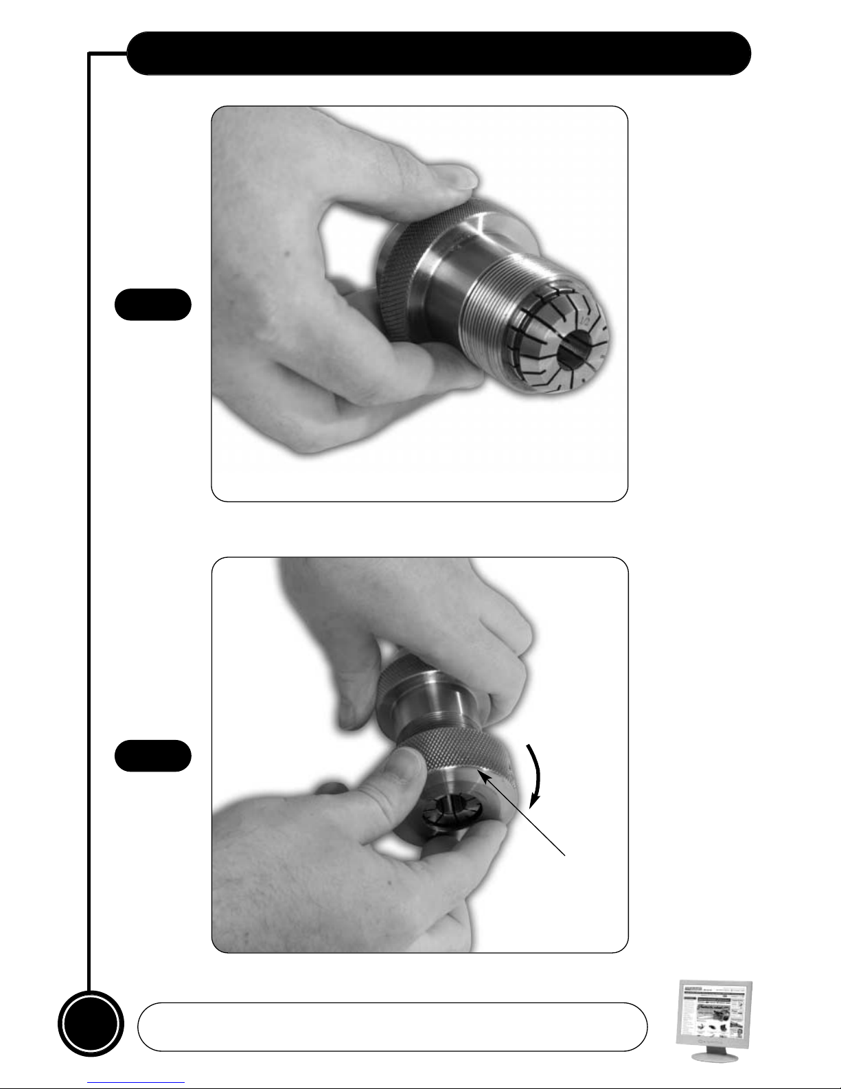
3. The kit includes 5 collets 6,10,12,16 and 20mm to grip dowels and tenons. Insert the
collet that is appropriate for your work; with the small tapered end first. Then thread the
sleeve nut loosely over it. (See figs 2,3 & 4)
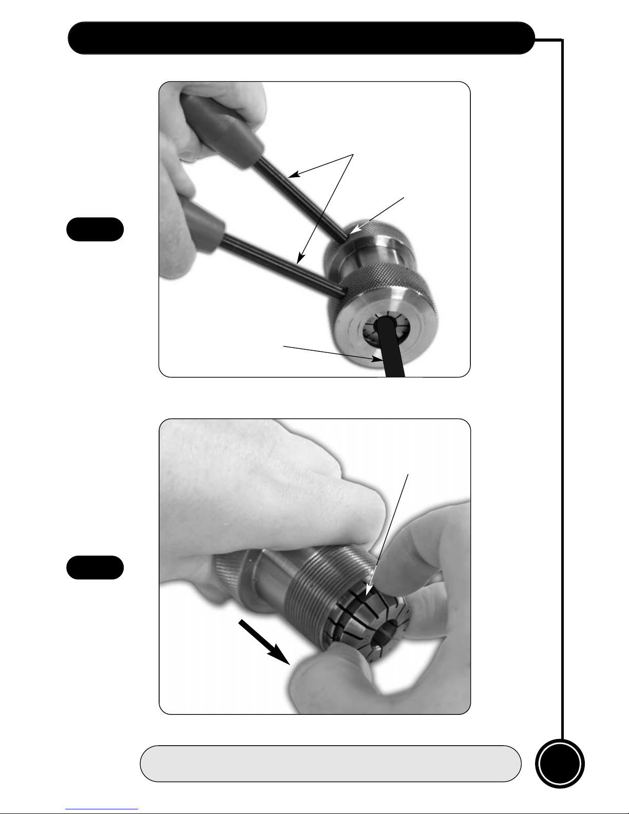
4. Insert the dowel or tenon of your work piece into the collet; and using the tommy bars
tighten the sleeve nut down to clamp it in position. (See fig 5) Ideally, the nut sleeve surface
should be flat with the surface of the collet for maximum support of the work piece. The
collet chuck is ready.
!
DISCONNECT THE LATHE FROM THE MAINS SUPPLY
!
THE PICTURES IN THIS MANUAL SHOW
THAT THE COLLET CHUCK HAS BEEN REMOVED
FROM THE LATHE FOR CLARITY
!
To replace the collet; unscrew the sleeve nut and insert the required collet, tapered end in
first, see fig 2 into the opening of the body. Replace the sleeve nut. (See fig 4)
Note: If the collet is jammed inside the chuck body, pull on the groove at the top of
the collet to release it from the chuck body. (See fig 6)
Replacing the Collet
Page 5
05
Operating Illustrations...
FREEPHONE 0800 371822
Fig 1
Fig 2
Lathe adapter
Chuck body
Collet
Page 6
06
Operating Illustrations...
www.axminster.co.uk
Fig 3
Fig 4
Collet inserted into the chuck body.
Sleeve nut
Page 7
07
Operating Illustrations...
FREEPHONE 0800 371822
Fig 5
Fig 6
Tommy bars
Blind pocket
Dowel
Collet groove
Insert a dowel or tenon into the collet and tighten the collet
with the tommy bars to clamp the work piece in position.
Page 8
700253
www.axminster.co.uk
Axminster Devon EX13 5PH UK
FREEPHONE 0800 371822
Collet Chuck System Set
 Loading...