

Page 1

WHITE
AXMINSTER
W
2000
2000
600515
600515
www.axminster.co.uk
Axminster Devon EX13 5PH UK
FREEPHONE 0800 371822
10-22mm Narrow
Crown Stapler
Axminster Reference No: AW422J
Axminster Reference No: AW422J
10-22mm Narrow Crown Stapler
User Manual
WHITE
AXMINSTER
W
www.axminster.co.uk
Page 2

WHITE
AXMINSTER
W
Index of Contents...
PPaaggee NNoo ..
Safety Protection Symbols
SAFETY!!
!
The symbols shown on the cover of this
manual advise that you wear the correct
safety protection when using this machine.
E
y
e
P
r
o
t
e
c
t
i
o
n
S
a
f
e
t
y
H
e
l
m
e
t
P
r
o
t
e
c
t
i
v
e
G
l
o
v
e
s
S
a
f
e
t
y
F
o
o
t
w
e
a
r
R
e
s
p
i
r
a
t
o
r
S
a
f
e
t
y
V
i
s
o
r
R
e
a
d
M
a
n
u
a
l
T
w
o
M
a
n
A
s
s
e
m
b
l
y
E
a
r
D
e
f
e
n
d
e
r
s
D
u
s
t
M
a
s
k
WHITE
AXMINSTER
W
15
Illustrated Parts List...
FREEPHONE 0800 371822
Index of Contents.......................................................................................................................... 02
Declaration of Conformity
………….………........……..…………...............................................03
What’s in the Box………….………........……..………….................................................................04
General Instructions and Recommendations whilst
using Air Equipment............................................................................................ 05-06-07
Specific Safety Instructions for the Stapler...................................................................08
Specifications
….………........……..…………...............................................................................08
Identification and Description of the Stapler.................................................................
09
Illustration and Parts Description of the Stapler......
...................................................... 10-11
Preparing your Stapler for Use......................................................................................11
Using your Air Stapler....................................................................................................12
Maintenance...................................................................................................................
12
Troubleshooting.............................................................................................................13
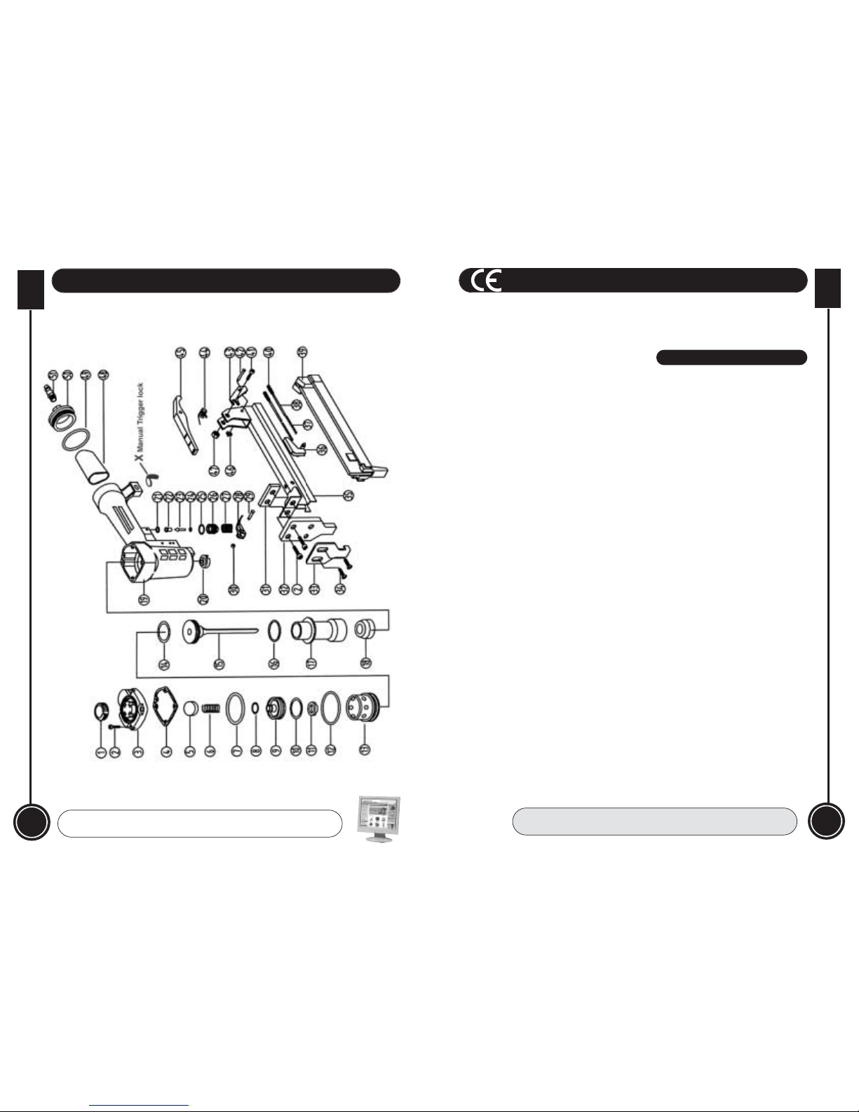
Illustrated Parts Breakdown...........................................................................................
14
Illustrated Parts List........................................................................................................
15
Page 3
WHITE
AXMINSTER
W
03
Declaration of Conformity...
FREEPHONE 0800 371822
The undersigned, O. Schiller authorised by
Chong Qing Hong Yuan Pneumatic Tool Factory
107 Jienan Street Banan District Chong Qing,
China
declares that this product:
Airnailer 422J
manufactured by Chong Qing Hong Yuan
Pneumatic Tool Factory is in compliance with the
following standards or standardisation documents
in accordance with Council Directives
98/37/EG / 98/37/EC
CCoo ppiieedd ffrroo mm CCEE CCeerrtt iiff ii ccaatt ee
14
WHITE
AXMINSTER
W
Illustrated Parts Breakdown...
www.axminster.co.uk
Page 4
WHITE
AXMINSTER
W
13
04
WHITE
AXMINSTER
W
What’s in the Box...
www.axminster.co.uk
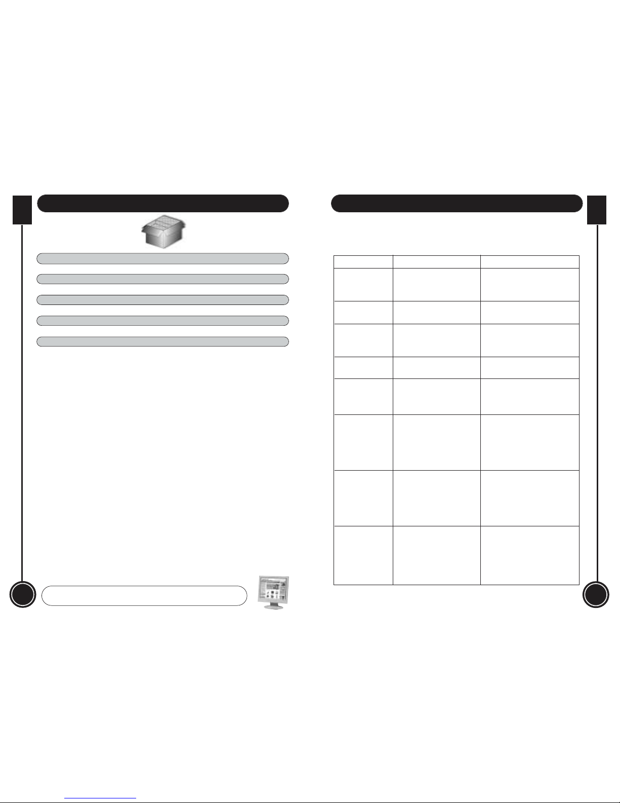
Troubleshooting...
Model Number: 422J
Quantity Item
1 No. 10-22mm Narrow Crown Stapler with PCL tail fitted.
1 No. Oil Bottle
1 No. 4mm Allen Key
1 No. 3mm Allen Key
1 No. Instruction Manual
Having unpacked the tool and its accessories, please check the contents against the
equipment list ”What's in the box”, if there are any discrepancies, please contact Axminster
Power Tool Centre using the procedures laid down in the catalogue. Please dispose of the
packaging responsibly; much of the material is bio-degradable. The tool is plated and
painted to prevent corrosion, so there should be little or no cleaning required before use.
Please read the Instruction Manual prior to using your new tool; as well as general
precautions and instructions for use, there are daily and periodic maintenance
recommendations to help you keep your tool on top line and prolong its life. Keep
this Instruction Manual readily accessible for any others who may also be required
to use the tool.
STOP USING THE TOOL IMMEDIATELY IF ANY OF THE FOLLOWING PROBLEMS
OCCUR. SERIOUS PERSONAL INJURY COULD OCCUR. ANY REPAIRS OR
REPLACEMENTS MUST BE DONE BY A QUALIFIED PERSON OR AN AUTHORISED
SERVICE CENTRE ONLY.
PROBLEM
PROBLEM CAUSE SOLUTION
Air leaking at
trigger area
Air leaking between
body and front plate
Air leaking between
body and cylinder
cap.
Blade driving
fastener too deeply
Runs slowly or has
power loss
Tool skips a fastener
Fasteners continually
“jam”
Tool will not drive
fully down
1.Joint guider is worn.
2.Fasteners are wrong size or
damaged.
3.Magazine or front plate screws
are loose.
4.Blade in piston assembly is
damaged.
1.Worn blade in piston assembly.
2.Lack of power.
3.Slow cycling and loss of power.
1.Replace piston assembly.
2.Adjust to adequate air pressure.
3.Check cylinder cap spring for broken
coils or reduced length. Check if
exhaust port of cylinder cap is
restricted.
1.Replace joint guider.
2.Use the recommended and
undamaged fasteners.
3.Tighten screws.
4.Replace piston assembly
1.O-ring in trigger valve is
damaged.
2.Trigger valve head is damaged.
3.Trigger valve stem, seal or O-ring
are damaged.
Damaged piston O-ring or bumper. Check and replace O-ring or
bumper.
1.Screw loose.
2.Damaged seal.
1.Worn bumper.
2.Air pressure is too high.
1.Insufficient oil.
2.Insufficient air supply.
3.Broken spring in cylinder cap.
4.Exhaust port in cylinder cap is
blocked.
1.Worn bumper or damaged spring
(17,18).
2.Dirt in front plate.
3.Inadequate airflow to tool.
4.Worn or dry O-ring on piston.
5.Damaged O-ring on trigger valve.
6.Cylinder cap seal leaking.
1.Replace bumper or spring.
2.Clean drive channel of front plate.
3.Check hose and compressor fittings.
4.Replace O-ring or lubricate.
5.Replace O-ring.
6.Replace seal.
1.Lubricate as instructed.
2.Check air supply.
3.Replace spring.
4.Replace damaged internal parts.
1.Replace bumper.
2.Adjust the air pressure.
1.Tighten screws.
2.Check and replace seal.
1.Check and replace O-ring.
2.Check and replace trigger valve
head.
3.Check and replace trigger valve
stem, seal or O-ring.
Page 5

12
WHITE
AXMINSTER
W
WHITE
AXMINSTER
W
Using your Air Stapler...
05
General Safety Instructions and Recommendations
whilst using Air Equipment...
The following suggestions will enable you to observe good working
practices, keep yourself and fellow workers safe and maintain your
tools and equipment in good working order.
Good Working Practices/Safety
Air Powered Tools
WARNING!!
!
KEEP TOOLS AND EQUIPMENT OUT
OF THE REACH OF YOUNG CHILDREN
Work Place/Environment.
Keep the tool clean; it will enable you to more easily see any damage that may have occurred.
Clean the tool with a damp soapy cloth if needs be, do not use any solvents or cleaners, as these
may cause damage to any plastic components. Check the tool for damage both before and after work.
If damage has occurred, have it repaired by a suitably qualified person.
Check the air lines are undamaged, that supply galleries, spurs or connectors are not leaking.
Keep the work area well lit and uncluttered as is practical, this includes personnel as well as material.
Under no circumstances should CHILDREN be allowed in work areas.
It is good practice to leave the tool disconnected from the air supply until work is about to commence,
when it is not in use, or unattended. Once you are ready to commence work, remove any tools used
in the setting up operations (if any) and place safely out of the way. Re-connect the tool.
Carry out a final check e.g. the connector is tight 'on', the air lines are not leaking, any bits etc, fitted
to the tool are secure, check you have the correct pressure set, and if you require to move around
during the work operation, that air lines etc, will not 'snag'.
Make sure you are comfortable before you start work, balanced, not reaching etc.,
Wear the appropriate safety clothing, goggles, gloves, masks etc., If the work operation or
environment appears to be excessively noisy, wear ear-defenders. If you wear your hair in a long
style, wearing a cap, safety helmet, hairnet, even a sweatband, will minimise the possibility of your
hair being caught up in the moving parts of the tool, likewise, consideration should be given to the
removal of rings and wristwatches, if these are liable to be a 'snag' hazard. Consideration should also
be given to non-slip footwear, etc.
Do not work with cutting or boring tools of any description if you are tired, your attention is wandering
or you are being subjected to distraction. A deep cut, a lost fingertip or worse; is not worth it!
Do not work with power tools of any description, if you are currently taking medication, unless you
have ascertained that your medication will not cause your judgement or awareness to be impaired.
Do not use this tool within the designated safety areas of flammable liquid stores or in areas where
there may be volatile gases.
Connect the stapler to the hose line, check there are no leaks anywhere in the system.
Organise a couple of pieces of scrap timber, preferably from the offcuts of the job you are
doing, and the material to be stapled to it and staple the two? items together. Remember,
there is no 'contact safety' fitted to this tool,the stapler will fire when the trigger is pressed.
Carry out several trial staplings, and then check you are driving the staples to the correct
depth. If not, adjust the air pressure (up or down) and carry out more trials, until you are
satisfied. You may have to set the 'staple height setting plate' in order to limit how deeply
the staple is actually driven, e.g. you may require to fasten cloth/covering, et al., to a frame
work, and the material is not sufficiently robust to resist severing if the staple is driven
through it?
Maintenance...
Keep the tool clean, and free from any splashes that may be picked up from current work,
e.g. paint, glue ,etc.
Frequent but not excessive oiling is the key to keeping your air tools working properly.
Lack of oil and ingress of water will damage your air tools. If your air system is not fitted
with water traps and in line oilers, make sure that the tool is not allowed to run 'dry' or to
retain moisture.
Keep the tool stowed safely away when not in use. Do not allow sawdust et al., to ingress
the tool.
OIL
Few drops of oil
( PNEUMATIC OIL ONLY)
Using the Oil supplied in the small oiler bottle, put 2-3 drops into the air connector.
It is always a good policy to add at least a drop of oil to the tool prior to the first
use of the day, even if you have automatic oilers fitted to your supply system. If you
do not have inline oilers, put 2-3 drops of oil into the tool first thing and then add 2
drops every 1-2 working hours.
Page 6
9
(B)
Small Workshop Installation
06
WHITE
AXMINSTER
W
WHITE
AXMINSTER
W
11
Illustration and Description of the Stapler...
General Safety Instructions and Recommendations
whilst using Air Equipment...
Check that cutters, drills, chisels etc., are the correct type and size, are undamaged and are kept
clean and sharp, this will maintain their operating performance and lessen the loading on the tool.
Above all, OBSERVE…. make sure you know what is happening around you, and USE YOUR
COMMON SENSE.
Installation
!
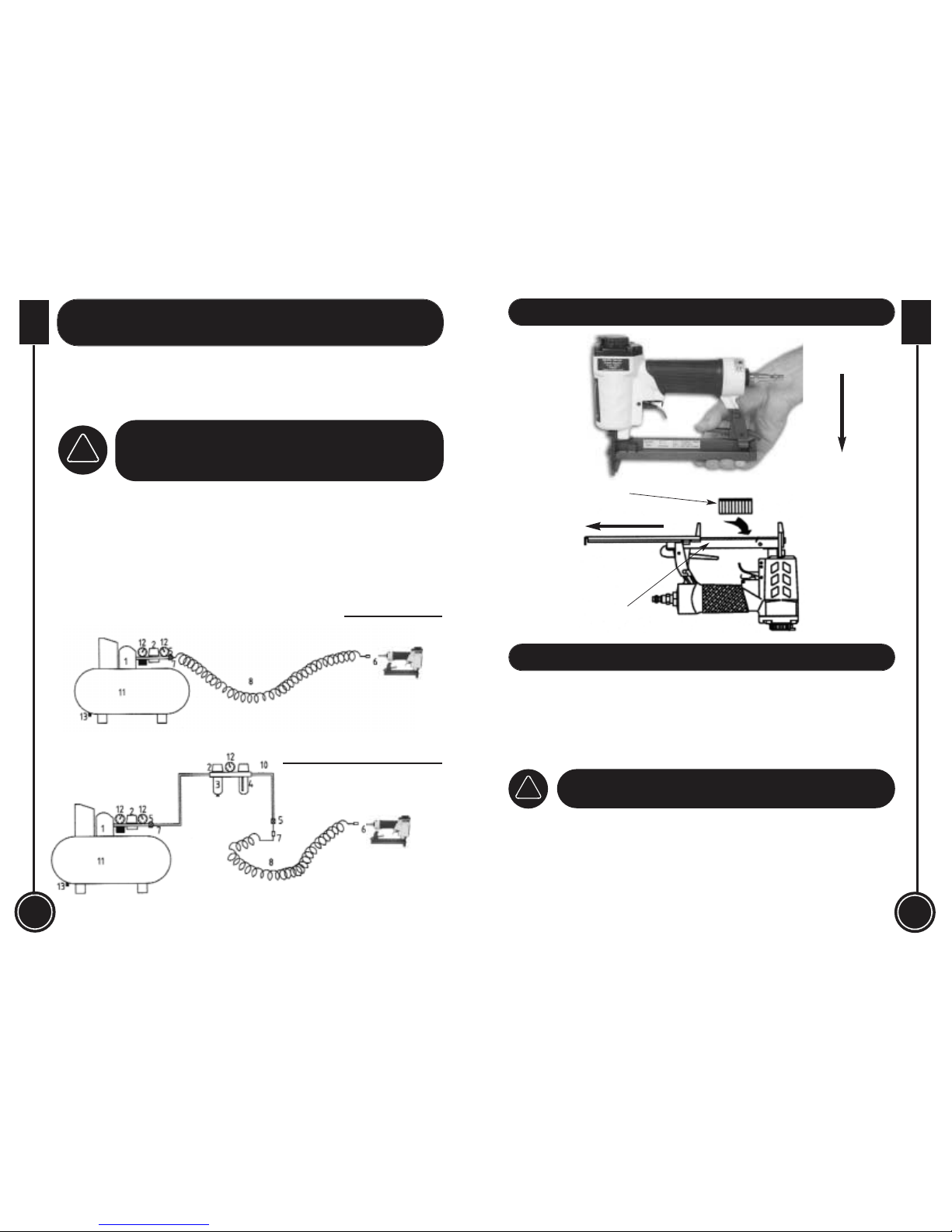
Please study the diagram of an air installation depicted below, any
new installation should follow these guidelines. Note. Fixed
connectors can be replaced with quick release connectors, but air
leakage can cause problems at the 'connection' as they become
worn.
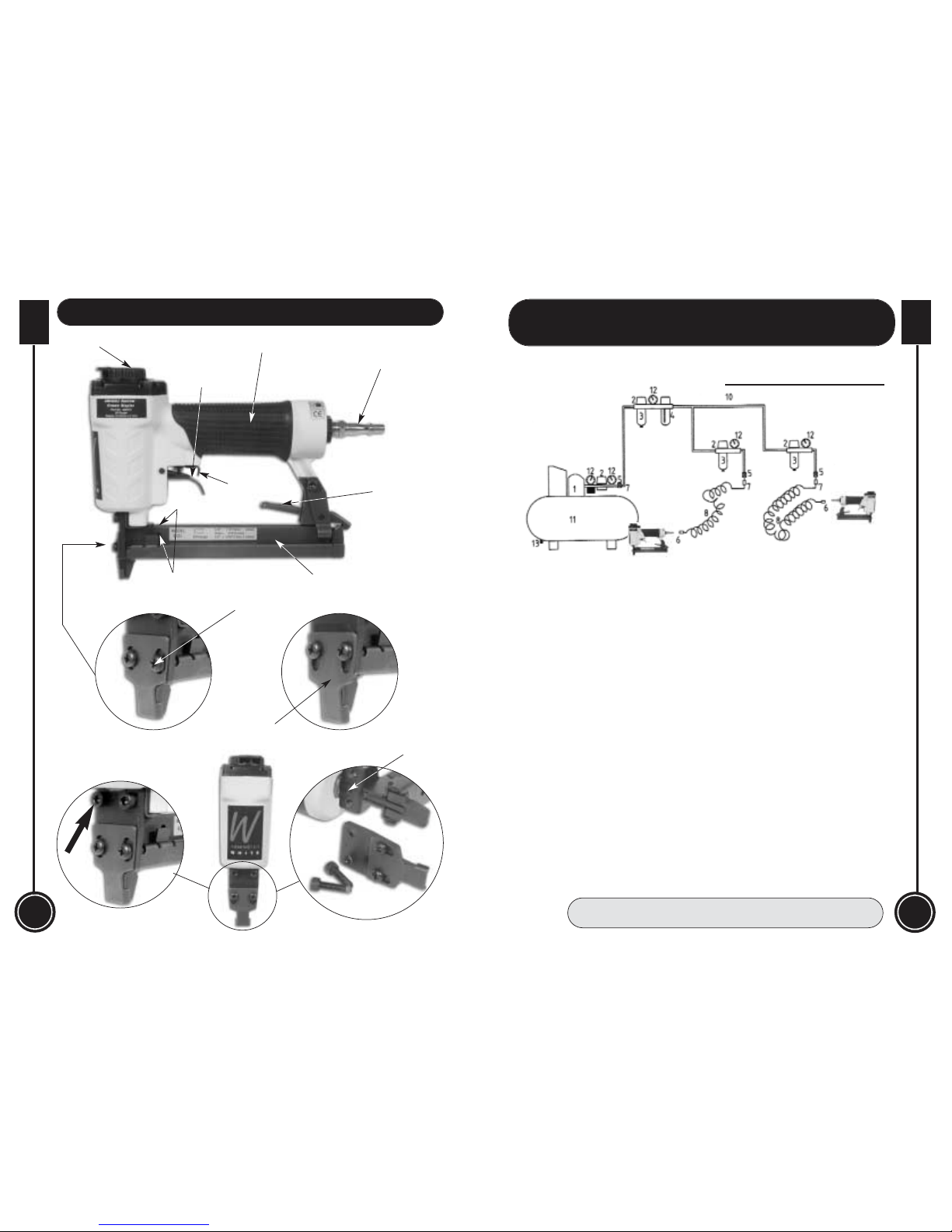
A) Basic Installation B) Small Workshop Installation C) Large Workshop Installation
Legend
1. Compressor 2. Regulator 3. Water trap 4. In line oiler 5. Shut off valve
6. Quick release connector 7. Fixed connector 8. Air line 9. Air tool
10. Air gallery 11. Reservoir 12. Pressure gauge 13. Water drain
9
(A)
Basic Installation
Push Latch down
Preparing your Stapler for Use...
Check your air supply system is on, and air is available in the gallery. (Check your inline
oilers, if fitted, have sufficient oil in the reservoirs). Turn on the air to the hose line. Set the
required pressure on the regulator (We suggest 70 psi).
Note: Remember you have to bleed air through the regulator to achieve the set pressure,
do this by opening the hose line using a blow gun or duster, and setting the regulator whilst
the air is flowing. Close off the air supply to check the set presure.
Magazine
Staples
DISCONNECT THE STAPLER FROM
THE AIR SUPPLY TO LOAD STAPLES
!
Unclip the magazine latch, and pull the magazine cover to the rear of the tool, turn the
stapler upside down exposing the staple trough. Load a clip of staples into the magazine
(Points upward). Carefully slide the magazine cover closed, so as not to break the pin clip,
or cause it to ripple. (the clearances around the rear slipper plate will govern the maximum
size of staple you can load into the tool, there is no physical check for the minimum size,
please read the specification and follow the guide lines). You will feel the resistance of the
sprung 'shoe feeder' against the clip of staples as the cover is closed, continue closing until
the cover latches shut. This 'shoe feeder' keeps the staples pressed into the receiver slot to
enable repetitious pinning.
Page 7
10
WHITE
AXMINSTER
W
WHITE
AXMINSTER
W
Illustration and Description of the Stapler...
07
FREEPHONE 0800 371822
General Safety Instructions and
Recommendations whilst using Air Equipment...
9
9
13
13
13
(C)
Large Workshop Installation
Main body
Quick release
connector
Magazine
slide latch
Air pulse divertor
Magazine assembly
View peepholes
Trigger
Typ. 2 Panhead screws
Staple height
setting plate
General Safety Precautions
Do not use a high pressure air system (greater than 20 bar) to supply power to this tool.
Ensure the air supply gallery to which your tool is connected has a pressure regulator
controlling the air pressure to 150 psi or less, and the supply for your tool can be further
regulated to the pressure you require.
Never use any form of compressed gas cylinder (air or any other) to supply power for your
tool.
Do not overload the tool or try to use it for a task for which it was not designed.
Only use the manufacturers spare parts to repair or refurbish tools and machines.
Be careful not to trip over air lines, be aware of their locations when they are deployed.
Do not point the tool at people or animals even in jest.
Use the correct connectors and correctly rated hose lines to connect your tool to the
supply.
Only use proprietary 'air lube' oils.
To avoid water contamination in the system/tools etc, remember to drain the
reservoir tank frequently.
Remove caphead bolts
to remove front plate in
order to clear “jam”
Striker guide body
Trigger safety
Page 8

08
WHITE
AXMINSTER
W
WHITE
AXMINSTER
W
09
Identification and Description of the Stapler...
If your air system does not use PCL fittings, and you have reason to change the connecting
method of the tool to your air supply, ensure that the new connector will not allow pressure
to be retained in the tool.
Ensure the supply does not exceed the maximum permissible pressure.
There is no safety enable with this tool, there is only a manual safety connected to the
trigger. Once the safety lock has been removed (a conscious action), the stapler will fire
when the trigger is pressed.
Do not use staples outside the recommended size range.
Clearing a Jam
If a fastener becomes jammed; before dissembling the gun;
DISCONNECT THE AIR SUPPLY.
Using the Allen Key provided undo the two caphead bolts that secure the front plate,
Remove the plates, clear the jam and replace the plates in the reverse order of removal.
Specific Safety Instructions for the Stapler...
Axminster No. 600515 (AW422J)
Maximum Operating Pressure 95 psi
Minimum Operating Pressure 60 psi
Air Inlet
1
/4" BSP with standard PCL Fitting
Air Consumption (constant usage) 3.8 CFM
Staple Gauge (20G) 1.2mm x 0.6mm (0.05" x 0.024")
Magazine Capacity 100 Staples
Maximum Staple Length 22mm
Minimum Staple Length 6mm
Staple Crown 11.2mm
Weight 1.3kgs
Footprint (without PCL tail) 56mm wide x 200mm long x 180mm high
Main body The main body is a casting that is extruded into the handle, the cylinder
housing, and the mounting points for the magazine assembly.
Connection port This is a
1
/4" BSP threaded hole which will allow you to mount the
connector of choice, to allow connection to the air supply.
Striker guide Basically a shaped metal plate, that is bolted to the lower mounting of
body the cylinder housing. It has a machined channel that guides the
striker/staple to the mouth when the stapler is fired.
Staple height A flat metal plate secured to the front of the striker guide body by means
setting plate of two panhead machine screws. The securing holes are elongated to
allow the plate to be moved up or down, so as to set the height of the
mouth above the work surface and thereby the driven height of the
staple. This is used when stapling something 'delicate' that could be
severed by just driving the staple home.
Magazine slide A sprung loaded latch that locks the magazine slide closed. It is
latch depressed to unlock the magazine slide to allow it to be withdrawn, to
facilitate the loading and unloading of the staples.
Magazine The magazine assembly is also secured to the lower mounting of the
assembly cylinder housing and supported at the rear underside of the handle. The
magazine basically consists of a 'U' shaped tray into which the staples
are laid, and the magazine slide plate, with a smaller inverted 'U' guide
fitted to it, which covers the fasteners, keeping them located in the tray.
Part of the slide plate mechanism is a sprung shoe that pushes against
the staples in the magazine tray and forces them into the receiver in the
guide body. The front end of the slide plate is the 'slipper' plate that
forms the rear part of the 'guide shute' down which the staples are fired.
The physical dimensions of the magazine assembly will limit the
maximum size of staples that can be inserted in the tool. There is no
such limitation on the minimum size, observe the figures in the
specification.
Trigger safety This is a manual mechanical safety device above the trigger proper. It
Lock locks the trigger off, so that a conscious action is required to ‘unlatch’
the trigger to allow the tool to be used. This is because there is no
‘contact safety enable’ mechanism built into these tools.
Trigger Provided it has been “unlatched”, pressing the trigger will allow the gun
to fire the staple into the material.
Viewing There are three peepholes in the magazine assembly to check whether
peepholes there are staples loaded.
Specification...
 Loading...