

Page 1
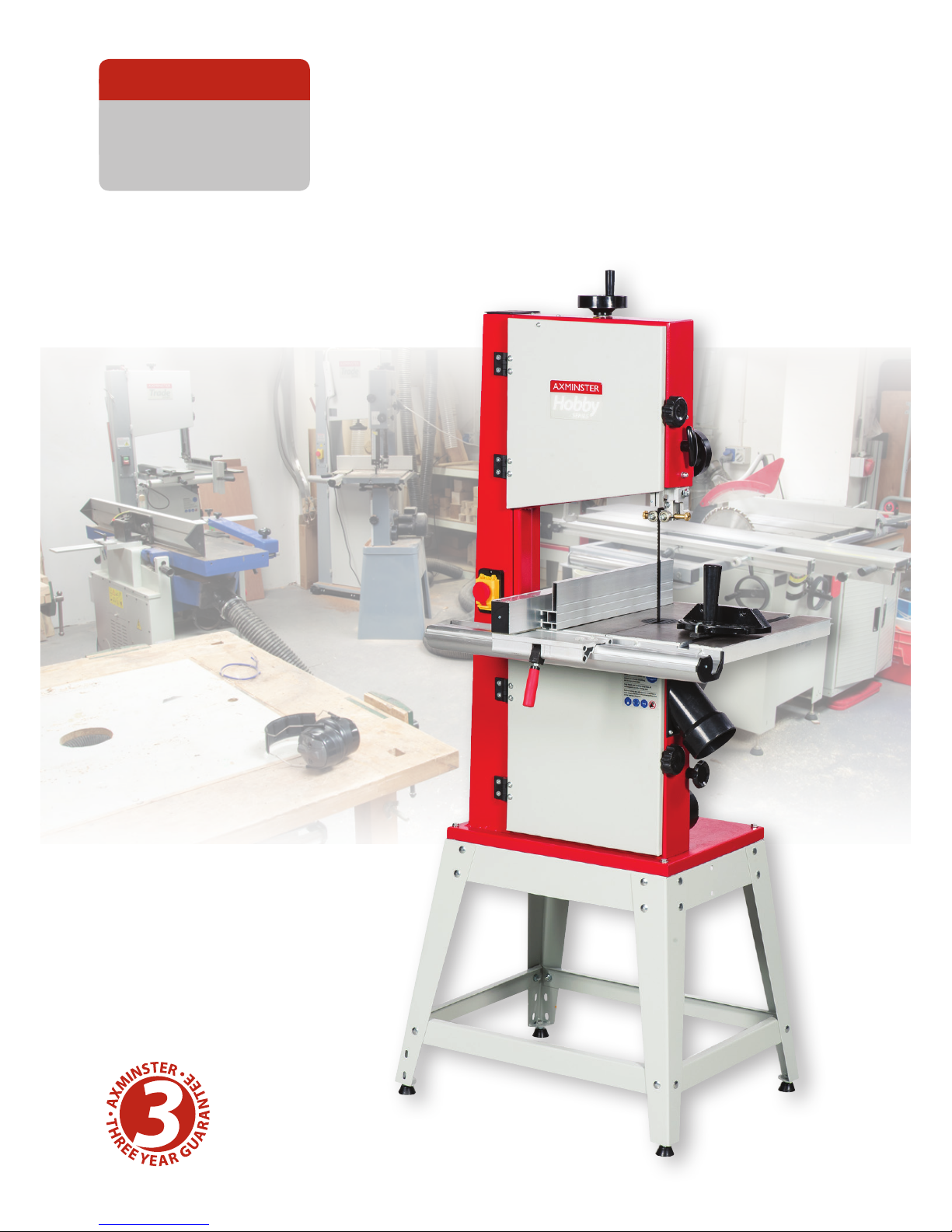
HBS310N 12”
Bandsaw
Code 508205
AXMINSTER
SERIES
Hobby
Page 2
Index of Contents
2
Declaration of Conformity
Warning
The symbols below advise that you follow
the correct safety procedures when using
this machine.
Fully read manual
and safety instructions
before use
Eye protection
should be worn
Ear protection
should be worn
HAZARD
Motor gets hot
Dust mask
should be worn
Two Man
Assembly
Page No
Index of Contents 02
Declaration of Conformity 02
What’s Included 03
General Instructions for 230V Machines 04-05
Specification 05
Unpacking 06
Stand Assembly 06
Mounting the Bandsaw to the Stand 07
Assembly 08-09
Illustration and Parts Description 10-11-12-13-14-15
Setting Up the Saw 16-17-18-19
Operating Instructions 19-20
Changing the Saw Blade 20-21
Changing the Blade Speed 22
Optional Wheel Mobility Kit 23
Routine Maintenance 24
Parts Breakdown/List 25-26-27-28
Wiring Diagram 29
Blades/Accessories 30
Notes 31
Copied from CE Certificate
The undersigned, (Roy Yongjun Xue)
authorised by Laizhou Chunlin Machinery Co., Ltd.
No. 1 Fuqian East Road
261400 Laizhou, Shandong
PEOPLE’S REPUBLIC OF CHINA
Model Number: MJ343B (Bandsaw)
Manufactured by Laizhou Chunlin Machinery Co.
is in compliance with the following standards or
standardisation documents in accordance with
Council Directives
2006/42/EC
EN 61029-1:2009
EN 61029-2-5: 2002
Page 3
Having unpacked your accessories please dispose of any unwanted packaging properly. The cardboard
packaging is biodegradable.
Please read the Instruction Manual prior to using your new machine; as well as the operating
procedures for your new machine, there are numerous hints and tips to help you to use the machine
safely and to maintain its efficiency and prolong its life. Keep this Instruction Manual readily
accessible for any others who may also be required to use the machine.
What’s Included
3
Quantity Item Model Number
MJ343B
1 No. HBS310N 12" Bandsaw (Code: 508205)
1 No. Bandsaw Blade 2,270mm long 4 TPI
blade assembled in the saw but not tensioned
1 No. Saw Table 1
1 No. Fence Guide and Extension 2
1 No. Mitre Guide 3
1 No. Packet containing the On/Off Switch Safety Shroud 4
1 No. Table Insert 5
Floor Stand comprising:
4 No. Threaded Rubber Feet A
4 No. Leg Brackets B
2 No. Upper Short Support Struts C
2 No. Lower Short Support Struts D
2 No. Upper Long Support Struts E
2 No. Lower Long Support Struts F
Bag Containing:
20 No. M8 x 18mm Coach Bolts G
20 No. M8 Nuts & Washers H
4 No. M8 x 40mm Bolts and M8 washers I
1 No. 5,4,3mm Hex Keys
Optional Accessories: (Code: 508207)
1 No Wheel Mobility Kit with M6 bolts nuts and washers J
1 No Lifting Handle Bracket K
Page 4
The following suggestions will enable you to
observe good working practices, keep yourself and
fellow workers safe and maintain your tools and
equipment in good working order.
Good Working Practices/Safety
Mains Powered Tools
Primary Precautions
Work Place/Environment
WARNING! KEEP TOOLS AND
EQUIPMENT OUT OF THE
REACH OF YOUNG CHILDREN
Ths machine is supplied with a moulded 13 Amp.
plug and 3 core power cable. Before using the
machine inspect the cable and the plug to make
sure that neither are damaged. If any damage is
visible have the tool inspected/repaired by a suitably
qualified person. If it is necessary to replace the plug,
it is preferable to use an ‘unbreakable’ type that will
resist damage on site. Only use a 13 Amp plug and
make sure the cable clamp is tightened securely. Fuse
as required. If extension leads are to be used, carry
out the same safety checks on them and ensure that
they are correctly rated to safely supply the current
that is required for your machine.
Make sure when the machine is placed that it sits
firmly on the floor; that it does not rock and is
sufficiently clear of adjacent obstacles so that cutting
operations will not be impeded. Check you have
adequate clearance both in front of and behind the
machine when cutting long stuff. If you are liable to
be processing unwieldy or awkward work pieces, it is
suggested that you consider fastening the machine
down to the floor.
The machine is not designed for sub-aqua operation,
do not use when or where it is liable to get wet. If the
machine is set up in the open, and it starts to rain
(unusual though this would be in U.K.), cover it up or
move it into the dry. If the machine has got wet dry it
off as soon as possible, with a cloth or paper towel.
Do not use 230V a.c. powered machines anywhere
within a site area that is flooded or puddled and do
not trail extension cables across wet areas.
Keep the machines clean; it will enable you to more
easily see any damage that may have occurred.
Clean the machine with a damp soapy cloth if needs
be, do not use any solvents or cleaners as these may
cause damage to any plastic parts or to the electrical
components.
Keep the work area as uncluttered as is practical, this
includes personnel as well as material.
(UNDER NO CIRCUMSTANCES
SHOULD CHILDREN BE
ALLOWED IN WORK AREAS)
It is good practice to leave the machine unplugged
until work is about to commence, also make sure to
unplug the machine when it is not in use or
unattended.
Always disconnect by pulling on the plug body and
not the cable. Once you are ready to commence work,
remove all tools used in the setting operations (if
any) and place safely out of the way. Re-connect the
machine.
Carry out a final “tightness” check e.g. guide fence,
table tilt, etc.., check that the ‘cutting path’ (in this
case the path that the work piece will travel) is
unobstructed.
Make sure you are comfortable before you start work;
balanced, not reaching etc..
If the work you are carrying out is liable to generate
flying grit, dust or chips wear the appropriate safety
clothing, goggles, gloves, masks etc., and if the work
operation appears to be excessively noisy, wear
ear-defenders.
If you wear your hair in a long style, wearing a cap,
safety helmet, hair net, even a sweatband, will
minimise the possibility of your hair being caught
up in the rotating parts of the tool. Likewise,
consideration should be given to the removal of
rings and wristwatches, if these are liable to be a
‘snag’ hazard. Consideration should also be given to
non-slip footwear, etc..
Do not work with cutting tools of any description
if you are tired, your attention is wandering or you
General Instructions for 230 V Machines
4
Page 5
are being subjected to distraction. A deep cut, a lost
fingertip or worse; is not worth it!
Do not use this machine within the designated safety
areas of flammable liquid stores or in areas where
there may be volatile gases. There are very expensive,
very specialised machines for working in these areas,
THIS IS NOT ONE OF THEM.
Check that blades are the correct type and size, are
undamaged and are kept clean and sharp, this will
maintain their operating performance and lessen the
loading on the machine.
Above all, OBSERVE…. make sure you know what
is happening around you and USE YOUR COMMON
SENSE.
Code 508205
Model HBS310N
Rating Hobby
Power 550W 230V
Blade Speed 360 & 720 m/min
Blade Length 2,270mm
Blade Width Min/Max 6mm (1/4”) to 16mm (5/8”)
Max Width of Cut 305mm
Max Depth of Cut 180mm
Max Width of Cut with Fence 265mm
Table Size 500 x 400mm
Table Height on Stand 1,005mm
Table Tilt -5° to +45°
Wheel Diameter 350mm
Dust Extraction Outlet 100mm
Overall L x W x H 760 x 720 x 1,700mm
Weight 80kg
Specification
General Instructions for 230 V Machines
5
Page 6
Your saw is packed in the box partially assembled.
This is to ensure that the components are inserted
in the correct positions. For example, the the blade
is fitted, the securing bolt for the tilt mechanism is
inserted in the tilt quadrant with the washer and the
locking butterfly nut threaded on to the bolt, etc.
Please make careful note of the positions of the
various components if you have cause to
disassemble, whilst putting the machine together.
Take all the easily removable items out of the box,
tip the box up so that the base of the saw is to the
ground, remove all the polystyrene packaging from
around the saw (open both sides of the box?) then
“corner walk” the saw out of the box.
If this is still awkward, split the top of the box, fold the
box material flat on the floor, and “wriggle” the saw
off the cardboard. ( The best method of moving the
saw is with a ‘hug’ lift through the neck of the saw,
holding the saw back against your body and lifting
by straightening your legs).
Stand Assembly
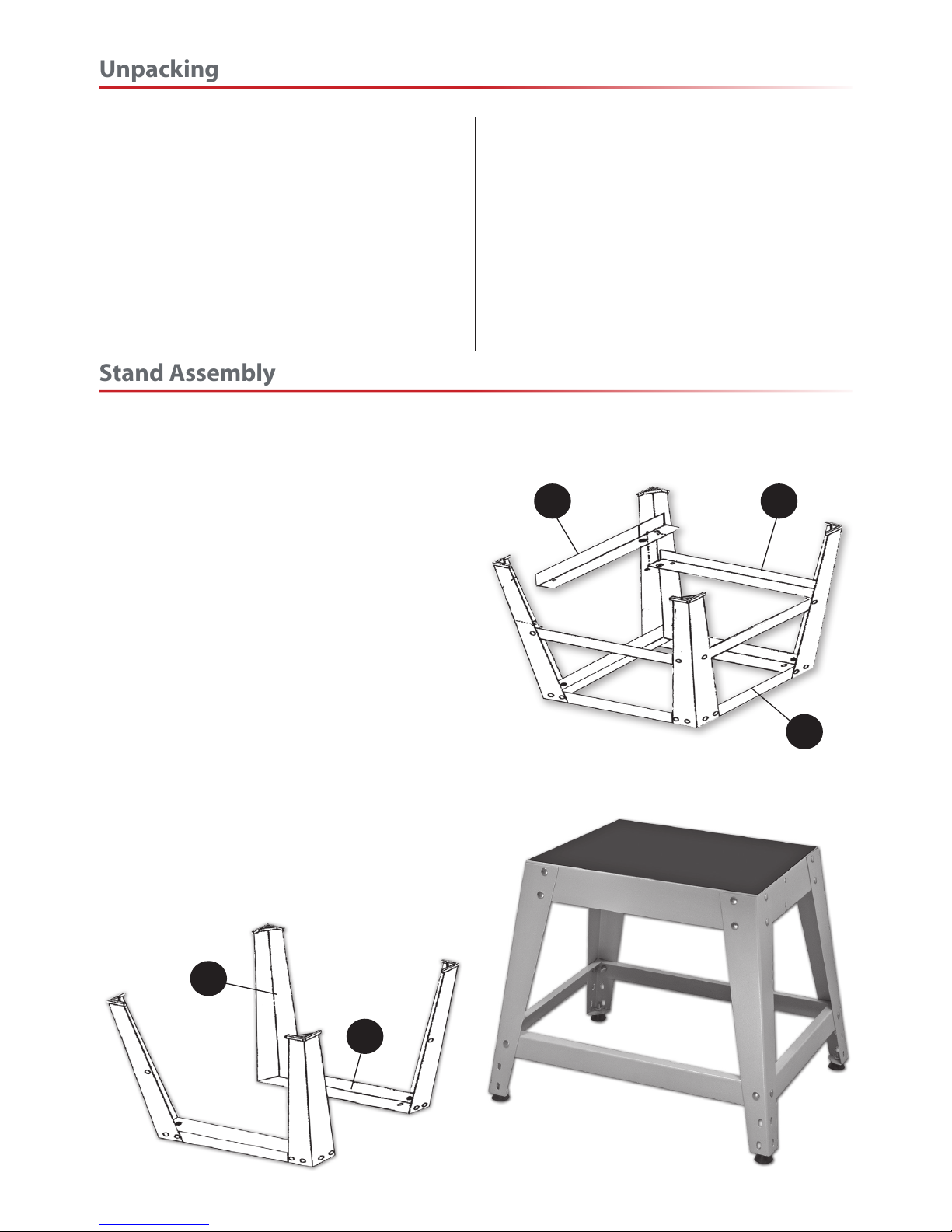
Locate and identify the 4 leg brackets (B), the upper
short struts (C), lower short struts (D), the upper long
struts (E), the lower long struts (F) and M8 x 18mm
coach bolts, washers and nuts(G & H).
Using the M8 coach bolts, nuts and washers bolt
together two legs (B) and one upper short strut (C),
‘finger tighten’ at this time, see fig 1.
When the two frames have been assembled,
select one, turn it upside down on a flat surface and
loosely bolt one of the ‘lower short strut’ (E) in place,
(see fig 2). Attach the other frame and bolt the
remaining strut (E) for the other side. Repeat the
procedure for the lower support struts (D-F).
When all the components are assembled, turn the
stand upright. Using the flat surface as a reference,
tighten up all the nuts, turn the stand on its side and
insert one of the four thread rubber feet (A) into one
of the four pre-drilled holes to the ends of the leg
brackets (B). Tighten in place with a M8 washer and
nut (H). Repeat for the remaining feet. Upright the
frame and stand it on the floor, see fig 3.
B
C
F D
E
Fig 01
Fig 02
Fig 03
Unpacking
6
Page 7
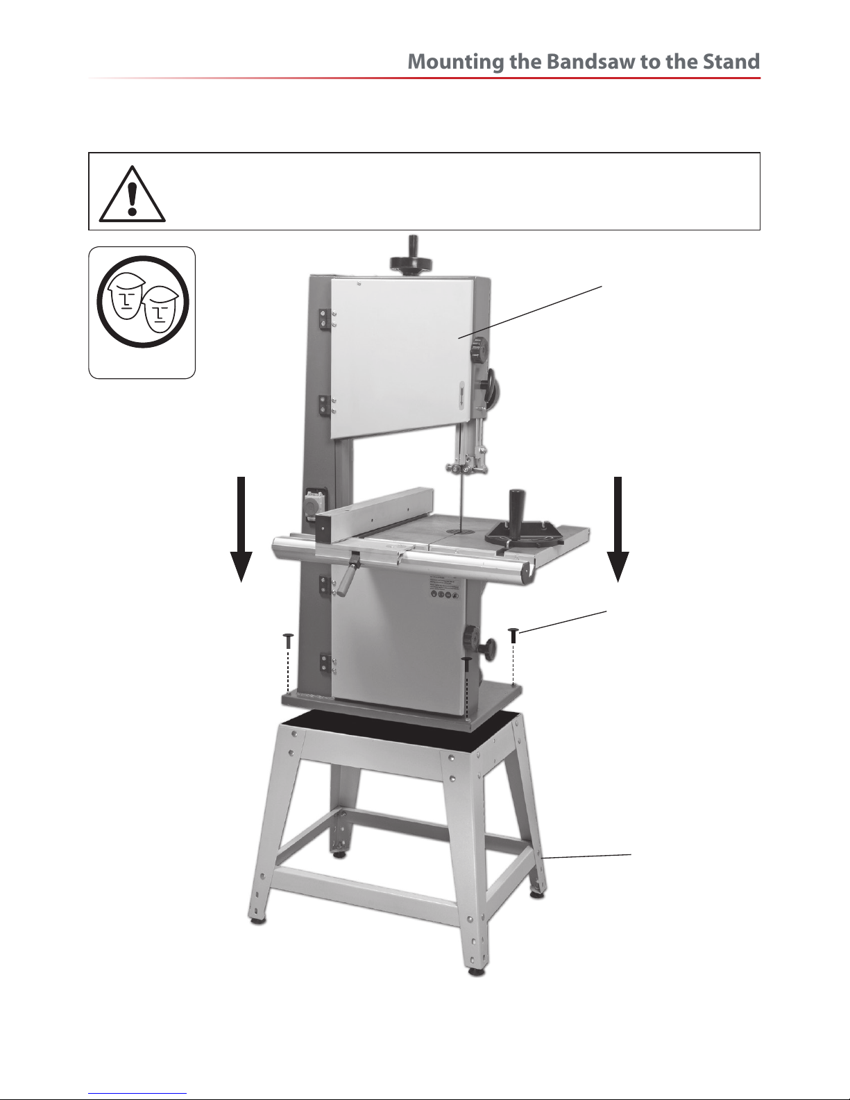
Lift the saw on to the cabinet, and secure using the 4 M8x40 bolts nuts and washers. ( Insert the bolts through
the base of the saw, through the floor cabinet and fit the washers and nuts on the underside).
Stand
Bandsaw
M8x40 bolt & washers
Please Note: the Illustration above shows the bandsaw with the table already assembled for clarity
WHEN MOUNTING THE UNIT, WE STRONGLY ADVISE YOU GET THE
ASSISTANCE OF ANOTHER PERSON BECAUSE OF THE WEIGHT OF THE
MACHINE.
Two Man lift
Mounting the Bandsaw to the Stand
7
Page 8
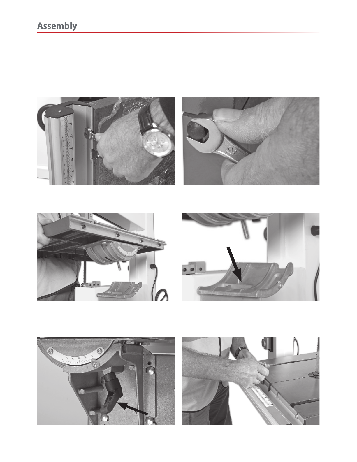
Mounting the saw table
The saw table can be fitted without removing the blade, however, if you would feel more comfortable not
having to manoeuvre the table around the blade (the table is quite heavy), remove the blade by opening
the top and bottom covers and release the tension on the blade by backing off the tensioning wheel.
Fig 01
Remove the fence rail and put safely aside.
Fig 02
Remove the table stabilising bolt
and table insert.
Fig 03
Remove the table clamping handle and washer beneath the table,place safely aside. Slide the blade through
the tables slot and lower the table, guiding the threaded bolt through the hole in the tilt quadrant housing.
Fig 03a
Fig 04
Replace the clamping handle and washer you
removed earlier, and tighten.
Fig 05
Replace the table stabilising bolt and
re-attach fence front rail. Replace the table insert.
Assembly
8
Page 9
Remove the two Phillips screws
from either side of the switch
assembly, see fig 7, slide the
switch shroud over the switch,
see fig 7a and secure using the
two Phillips screws you removed
earlier.
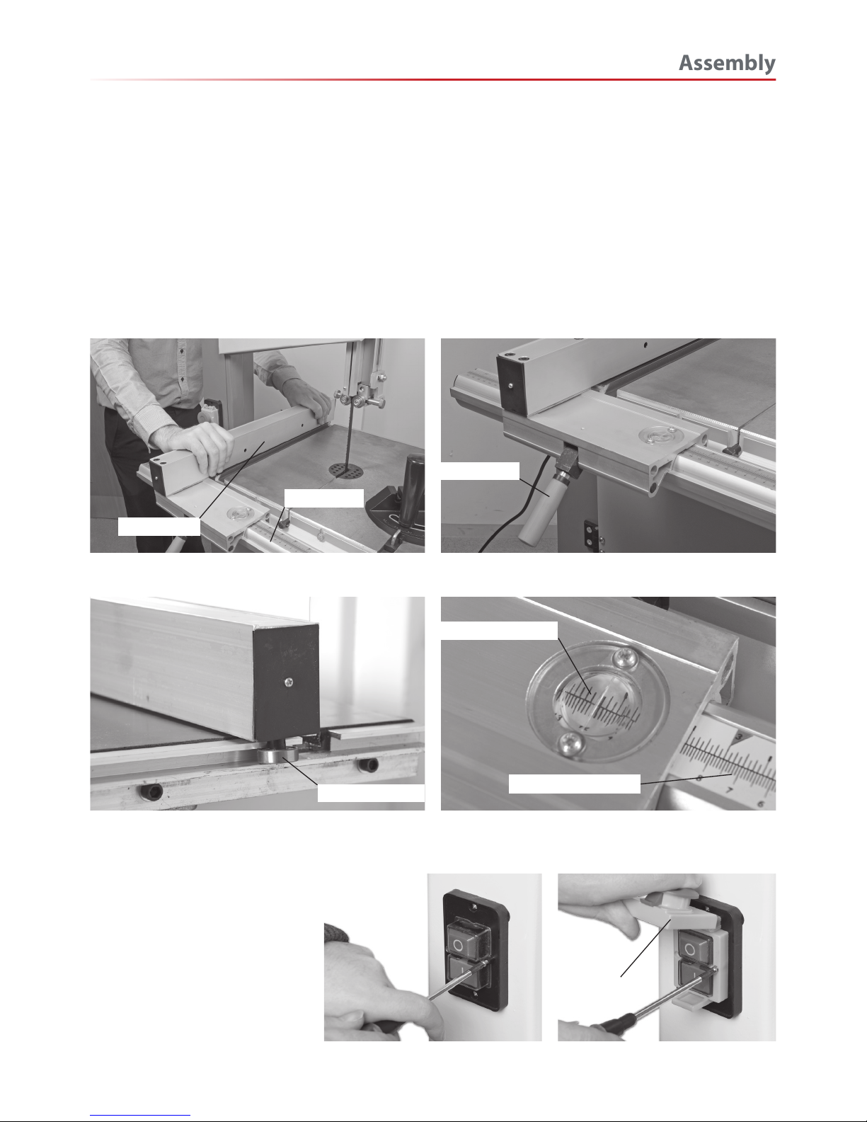
Fitting NVR switch shroud
Fit the guide fence by clipping the rear clamp over
the back rail first and dropping the front clamp over
the fence rail, see fig 6 Push down on the lock lever,
and ensure the fence clamps up correctly.
see fig 6a.
Check the guide fence is set parallel to the blade. Any
slight discrepancy can be taken out by loosening the
4 butterfly bolts that secure the blade of the guide
fence to the clamping body, adjust and re-tighten.
Larger discrepancies may require that the fence rail
is angled slightly.
The dimensioning scales have adjustable index plates
set in the fence guide front clamp body to enable the
scales to be zero read, see fig 6c .
Fitting the guide fence
Fig 06 Fig 6a
Fig 6b Fig 6c
Fig 7
Fig 7a
Guide fence
Fence rail
Guide bearing
Dimensioning scale
Magnifying glass
Lock lever
Switch
shroud
Assembly
9
Page 10
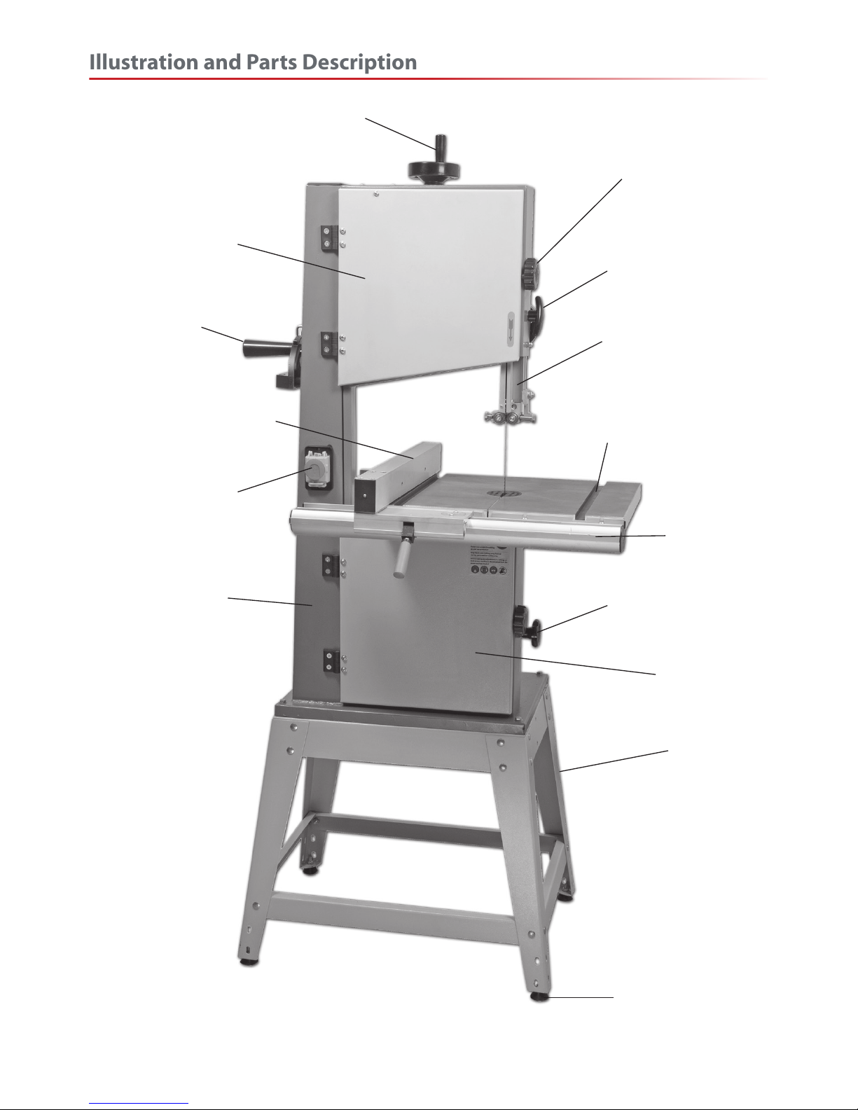
Upper door locking knob
Upper blade guide clamp
Upper blade guide & guard
Fence guide rail
Lower wheel door
Bandsaw stand
Idler wheel adjusting knob
Saw table ‘T’ slot for mitre fence
Main saw frame
Guide fence
Mitre fence
ON/OFF button
and switch shroud
Upper wheel door
Stand rubber foot
Blade tensioning wheel
Illustration and Parts Description
10
Page 11
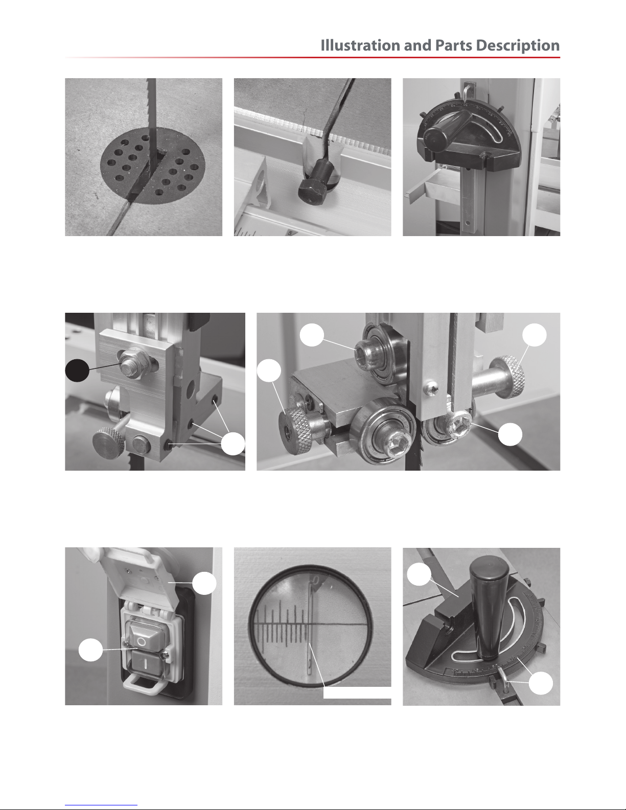
Table insert plate Stabilising bolt
Fore and aft clamping nut (A)
Lateral adjustment clamping grub screws (B)
Rear thrust bearing (A), Upper bearing blade guides (B)
Blade guide bearing adjusting knobs (C)
ON/OFF NVR switch assembly (A)
Emergency stop shroud (B)
A
B
A
Mitre fence holder
Magnifying glass with index marker
Index marker
Mitre fence assembly (A)
Index and pointer (B)
A
B
A
B
C
CA
B
Illustration and Parts Description
11
Page 12
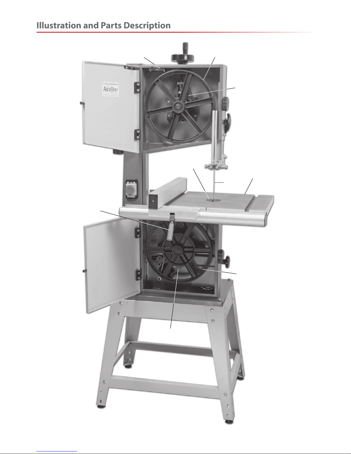
Upper saw wheel
Upper wheel mounting
Saw table
Table insert
Locking lever
Saw
Drive pulley
Micro door switch
Lower saw wheel
Illustration and Parts Description
12
Page 13
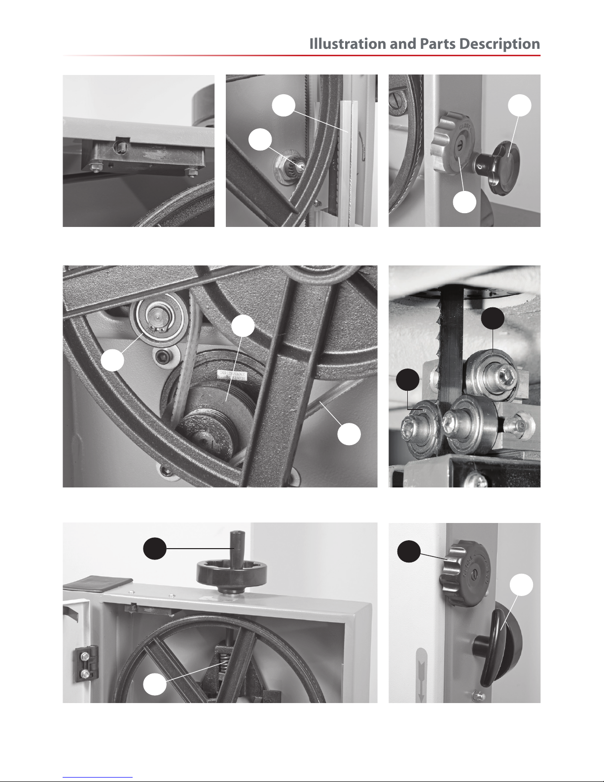
Micro door switch Upper blade guide and guard (A)
Upper blade guide drive (B)
Idler wheel adjusting knob (A)
Lower door lock (B)
Drive pulley (A), Drive belt tensioning idler wheel (B), Drive belt (C)
Lower bearing blade guides (A)
Lower rear thrust bearing (B)
Belt tensioning wheel (A), Blade tensioning assembly (C) Upper door lock (A)
Upper blade guide clamp (B)
A A
B
B
A
B
C
B
A
A
C
A
B
Illustration and Parts Description
13
Page 14
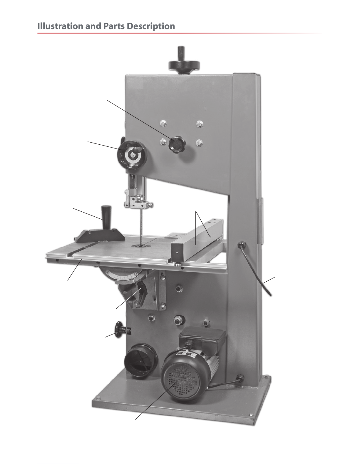
Rear guide rail
Mitre fence
Power lead
Tracking control knob
Upper blade height
adjusting wheel
Motor
Table clamping handle
Idler wheel adjusting knob
100mm Dust extraction
Fixing holes for fence
extension (NOT SHOWN)
Illustration and Parts Description
14
Page 15
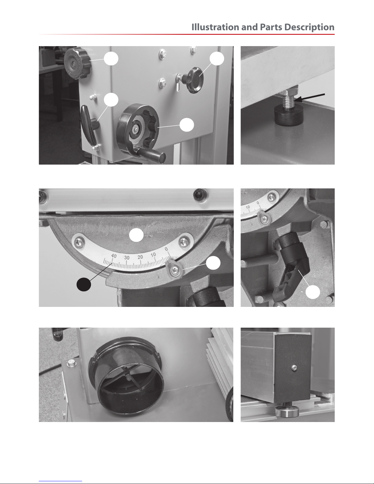
Table levelling stop bolt
100mm Dust extraction outlet
Table clamping handle (D)
Upper door lock (A), Upper blade guide height clamp (B)
Upper blade guide height adjusting wheel (C), Tracking control knob (D)
A
B
C
D
Tilt quadrant (A), Tilt scale (B)
Tilt scale pointer and adjusting screw (C)
A
C
Fence guide bearing assembly
D
B
Illustration and Parts Description
15
Page 16
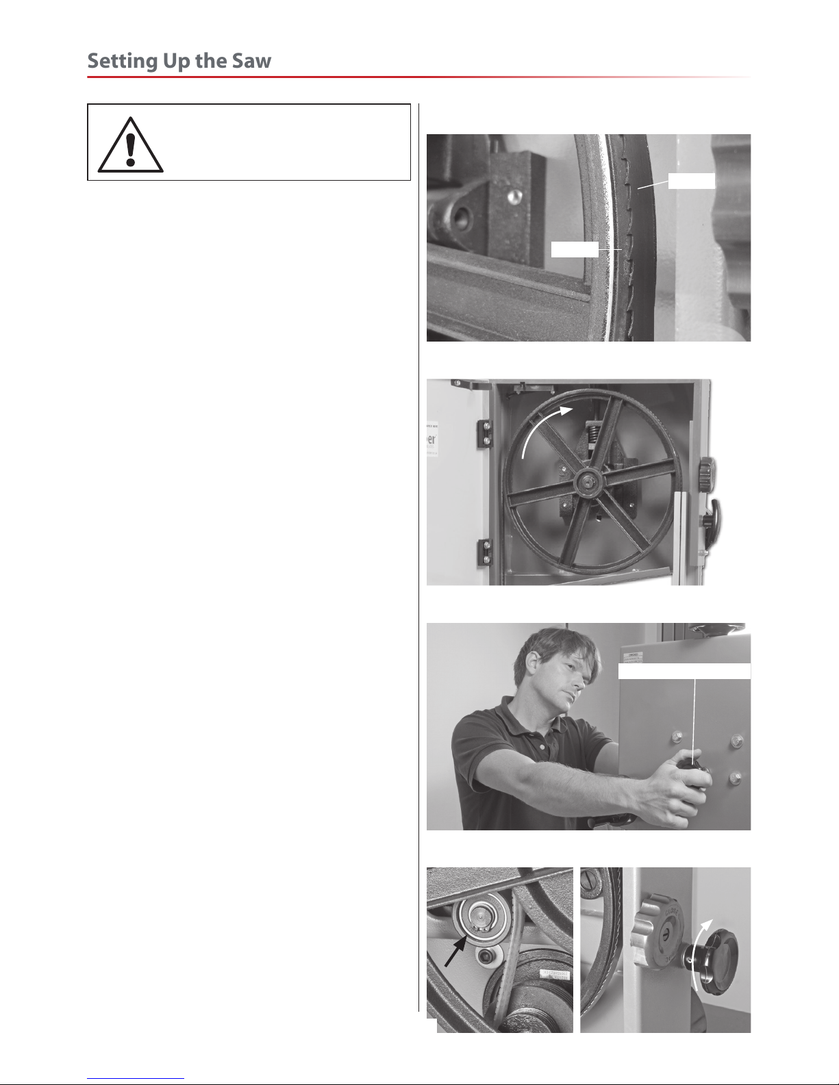
Tensioning and tracking the blade
DISCONNECT THE SAW
FROM THE MAINS SUPPLY!
Make sure both top and bottom blade guides are
well clear of the blade.
Open the front covers fully, giving good access to the
top compartment of the saw and good visibility into
the bottom compartment (see page 12). For tracking
the blade first adjust all bearing guides so that there
well clear of the blade. Check that the blade is sitting
approximately in the middle of the wheels, see fig
08. Apply some tension to the blade by turning the
tensioning wheel clockwise, spin the top wheel by
hand and check that the blade remains centrally on
the tyre, see fig 09. If it does not, adjust the tracking
by turning the tracking control at the rear of the head
box, see fig 10. Viewed directly onto the tracking
control wheel, turning clockwise should cause the
blade to track to the rear of the tyre; anti-clockwise to
the front, DO NOT make large adjustments.
Spin the top wheel again, check again. Continue until
the blade tracks in the centre of the tyres with no
appreciable to and fro movement. Tension the blade
fully. (A sideways push of about 7-8 lbs(3+kgs) in the
middle of the blade should allow a 1/4” (6.5mm)
distension. Check the tracking again, adjust if
necessary. Check that the drive belt is tensioned
correctly. If it is slack, apply ‘take up’ pressure to the
belt by adjusting the ‘Idler’ pulley, using the knob at
the side of the machine, see fig 11.
Connect the power to the machine. Stand clear and
start the saw. Check that the saw is running smoothly,
(no thumps, bumps, knocking or excessive vibration)
and the blade appears to be tracking correctly (in
one place). You can check this by holding a marker,
e.g. a pencil, close to the back of the blade (approach
from the back of the blade only) and check that the
gap remains constant.
If it doesn’t, adjust the tracking until it does. Make
very small adjustments and wait for the saw to react
before you adjust again, sometimes the reaction is
not instantaneous. Once you are satisfied that the
tracking is correct switch the machine off and allow it
to run to a stop.
Fig 08
Fig 09
Blade
Tyre
Fig 10
Tracking control knob
Fig 11
Setting Up the Saw
16
Page 17
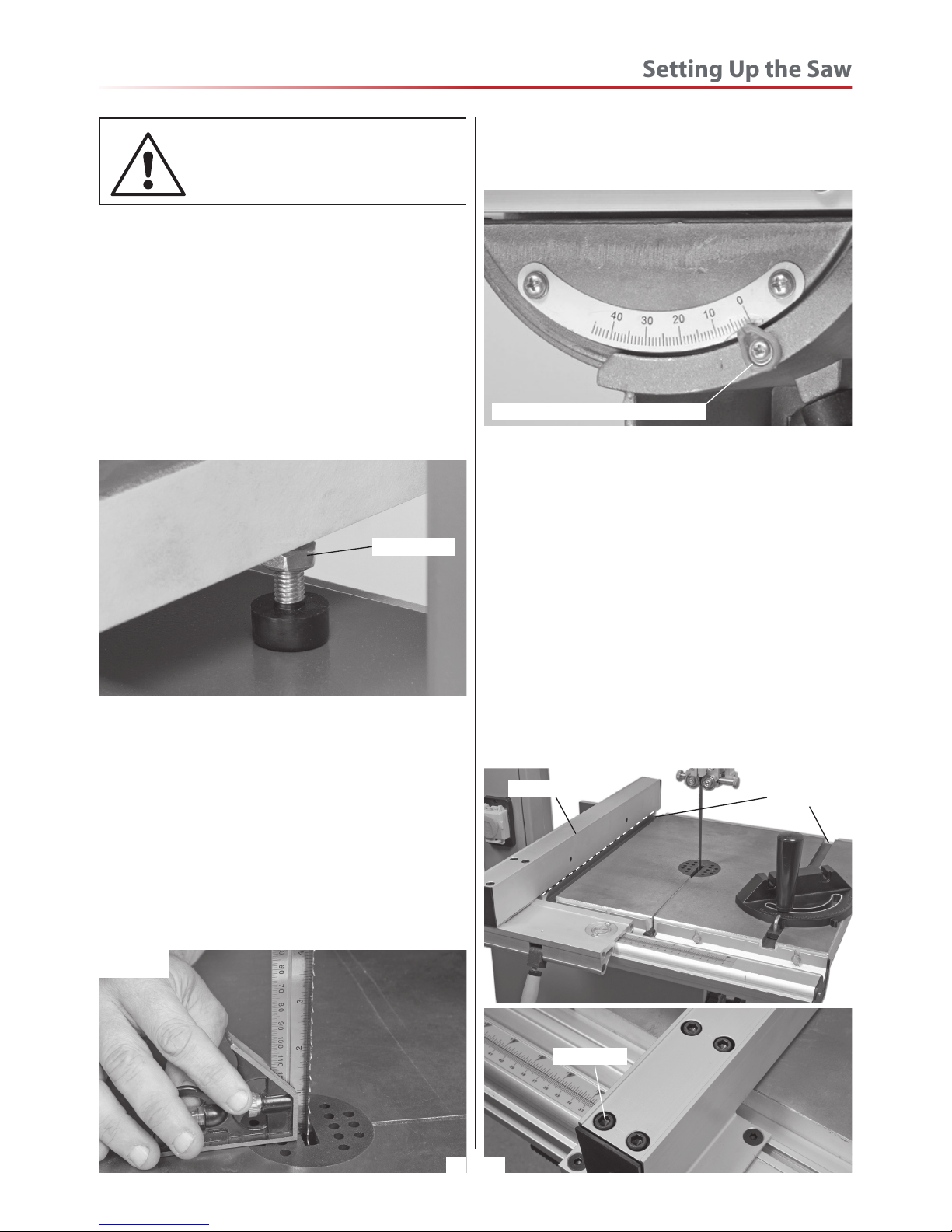
Checking the table is square
DISCONNECT THE SAW
FROM THE MAINS SUPPLY!
Loosen the clamping handle beneath the table
clamping the tilt mechanism, and turn the table hard
against its stop. This is a bolt with a lock nut screwed
into the underside of the table,see fig 12. The head
of the bolt has a rubber foot that acts as a stop when
it strikes the machine frame. Tighten the clamping
handle.
Fig 12
Make sure the upper blade guide is raised as high as
possible. Place a square on the table and move it up
against the blade (behind the teeth),see fig 13.
Check that the blade is perpendicular to the table. If
it is not, try resetting the table. If it is still not correct,
loosen the table locking handle and adjust the bolt
until perpendicularity is achieved, see fig 12. Tighten
the lock nut and then re-check. When you are
satisfied that the table is set correctly, check that the
pointer of the tilt gauge reads zero, if not, adjust it,
Fig 13
Locking nut
see fig 14. Retighten the table clamping handle.
Fig 14
Index pointer & adjusting screw
Setting the Fence
To make sure the guide fence is at 90˚line up the
guide fence with the edge of the table’s ‘T’ slot, see
fig 35. If you find that the fence is out of alignment
follow the steps below:
• Clamp down the fence by pushing the locking
lever down.
• Loosen the 4 Hex bolts that secures the fence rail
and adjust until the fence is in alignment with the
‘T’ slot, then re-tighten the bolts, see fig 15.
• Replace the extension fence.
Fig 15
‘T’ slots
Fence
Setting Up the Saw
Hex bolts
17
Page 18
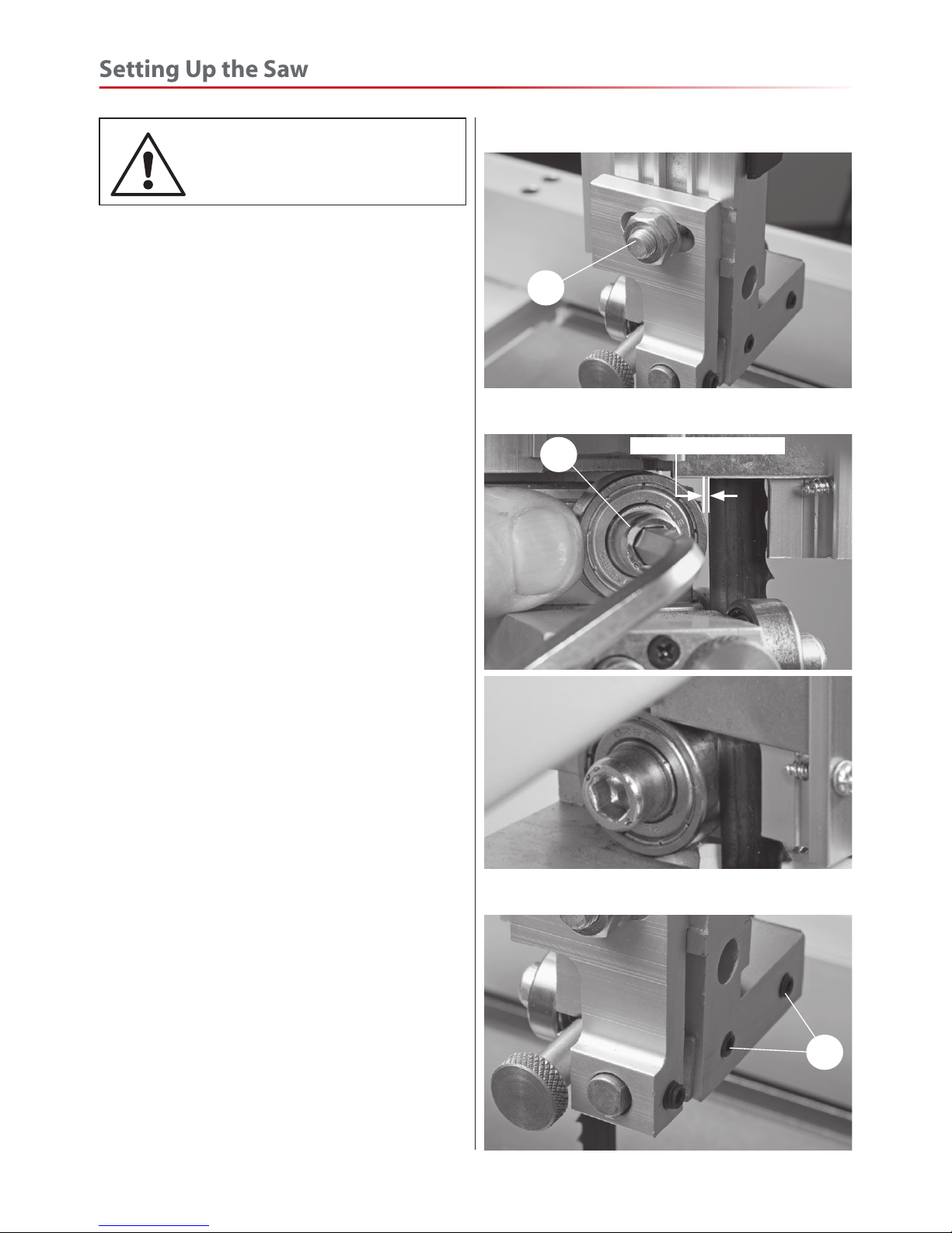
DISCONNECT THE SAW
FROM THE MAINS SUPPLY!
Lower the upper blade guide to approximately
1 1/2”(38mm) above the table. Clamp in place.
Loosen the nut (A) holding the guide assembly in
place and adjust thefore and aft position so that
the leading edges of the side guide bearings are
approximately 2mm behind the gullets of the saw
blade. Re-tighten the nut, see fig 16. Loosen the cap
head bolt that clamps the rear thrust bearing in
position (B) and adjust the thrust bearing to
approximately 1mm behind the blade, re-tighten
the bolt, (see fig 17). The blade should lineup with
the centre of the thrust bearing, if not loosen the
two grub screws (C) and move the upper blade
guide assembly in until correct, see fig 18. Retighten
the grub screws.
Loosen the two cap head bolts holding the guide
bearings (D) and move to approximately 0.5mm from
each side of the blade. NOTE: A five pound note is
approximately 0.5mm thick, slide a note between
the blade and guide bearing,turn the adjusting
knob (1), until the guide bearing is set to the correct
thickness. Re-tighten the bolts (D), see fig 19. Repeat
for the other guide bearing. Gently push the blade
back against the thrust bearing (use a scrap of wood,)
and check that the side bearings are still behind the
teeth of the blade.
Beneath the table, remove the safety guard and place
aside, loosen the two cap head nut holding the lower
blade guide assembly in place and position similarly
to the upper guide assembly, see fig 20. Re-tighten
the nut. Note: The guide bearing should always
be set behind the teeth of the saw.
Rotate the top wheel by hand, at this point. None
of the bearings should come into contact with the
blade-only when in use.
Adjust the lower blade guides, and set them similarly
to the upper guides, (D ) using an Hex key to release
and tighten the clamping bolts. When all adjustments
Setting the Blade Guides
Fig 16
A
Fig 17
B
2mm behind the blade
Fig 18
C
Setting Up the Saw
18
Page 19
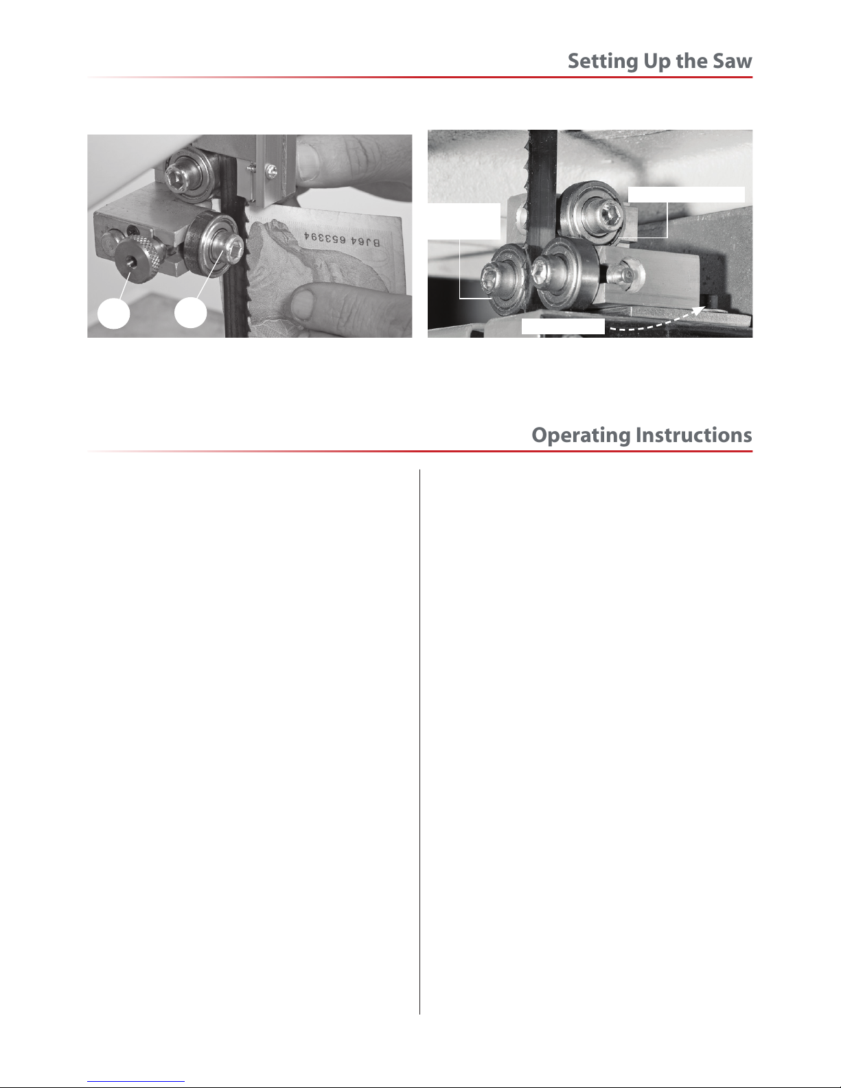
have been made, recheck that when the blade is pressed back against the thrust bearing, both the upper
and lower side guides are still behind the teeth of the saw, replace the safety cover. When all adjustments are
complete re-connect the power, switch the saw on, allow to run for several minutes, check that the blade is
still tracking correctly, there is no excessive vibration, etc. Switch off. The saw is ready to be used.
Fig 19
D
1
Fig 20
Lower guide
bearing
Cap head nut
Rear thrust bearing
Operating Instructions
1. Make sure you have read and fully understood
the general instructions and safety precautions
that are printed in the preceding pages of this
manual.
2. Before connecting the machine to the supply;
check the tool for obvious signs of damage, paying
particular attention to the plug and the power
cable. Rectify or have rectified any damage you
discover. Check that the blade you are using is the
correct one for the job in hand. Change the blade if
necessary. Check the blade is not damaged; is clean,
sharp, tracks properly and is correctly tensioned.
3. Set the upper blade guide to approximately
12mm (1/2”) above the height of the work piece.
4. Check especially on site, that there are no foreign
objects e.g. old nails, screws, small stones etc
embedded in the material you are about to cut.
5. Check that all accessories, tools etc., that have been
used to set the machine up, are removed and set
carefully aside or stowed away correctly.
6. Ensure the machine is switched off. Plug the power
cable into a correctly rated switched socket outlet.
If extension leads are being used, check these for
damage, do not use if damaged; if you are working
outside, check that any extension cables in use are
rated for outside work. Switch on. Allow the saw to
run up to speed.
7. Make sure that the material you are about to cut
is within the machine is capacity, and the cut you are
about to make is within the blade’s capabilities, e.g.
don’t try and cut a 1” radius curve using a 5/8” blade.
8. Make sure the blade is not in contact with the
material when you start the saw. Start the cutting
operation. Do not try to cut too quickly; the correct
cutting speed, if one could be so precise, would never
see the blade pushed back against the thrust be aring,
the saw would cut and clear the saw line at the rate
the work piece was fed into it. If you notice that you
require more and more pressure to effect the cut,
and the blade is in continual contact with the thrust
bearing, the chances are the blade is becoming blunt.
Check and change if necessary.
Do not let go of the workpiece, if you have to change
your grip, make sure one hand is holding the material
at all times.
9. If you are cutting long pieces of material think
about sawing cutouts (i.e. a saw cut from the edge
of the material to the saw line) along the saw line
so that you can discard the offcuts as you progress
down the saw line.
10. Observe the old woodworkers’ adage of never
allowing your hand/fingers within one hand breadth
of the blade.
Continues Over...
Setting Up the Saw
19
Page 20
11. If you have to cut very small pieces of material,
arrange or manufacture some form of ‘shoe’ to carry
the timber. If the work piece is exceptionally small,
find something to use as a sacrificial carrier and
mount the work piece on it with double sided tape,
or similar.
12. Remember to check the blade tension after a
new blade has been ‘working’ for 30-60 mins. The
blade will ‘stretch’ slightly when new.
13. Do not release the tension on the saw blade
when work is complete. The blades and the main
saw frame do not respond kindly to constant
changes in stress and tension. Only release the
tension to change the blade or if the blade is to be
removed because the machine is to be ‘mothballed’
for a lengthy time period. (The blade in tension over
a long period of non-use will cause the tyres
to develop ‘flat’ spots). Open the saw cut, either by
pulling apart or driving a wedge in close to the back
of the blade. Try to wriggle the blade free of the saw,
if this is not possible; check that the saw is free in
the cut, start the saw, allow it to run up to speed and
‘cut out’ as quickly as possible. The removal of the ‘off
cut’ may well prevent the saw jamming again if you
resume the original cut.
Changing the Saw Blade
DISCONNECT THE SAW
FROM THE MAINS SUPPLY!
Put the table back to the level position if it has
been tilted. Set the upper blade guide assembly
approximately midway in the throat. Open the top
and bottom covering doors. Remove the table insert.
Loosen the 4 bolts that hold the fence guide rail
to the table, and remove the rail. Remove the table
stabilising bolt, slacken the blade tension by turning
the blade tensioning wheel anti-clockwise, until the
blade can be easily slipped off the wheels. Remove
the blade carefully, “wiggling” it clear of the upper
blade guard and through the plastic lower blade
guard and out through the slot in the table.
NOW is an excellent time to clean out the interior of
the machine, remove the impacted ‘crud’ from the
tyres, apply a little light oil to the screw threads of
the blade and drive belt tensioners, and the tracking
control. The pivots and the slides of the top wheel
mounting assembly and the captive stub axle of
the drive belt tensioner in its slot could likewise be
lightly oiled. If you are fitting a new blade; it will have
been supplied to you “folded”, bound together in this
configuration with tape or tie wrap. Also check that
the blade did not “unfold” inside out. i.e. looking at
the right side front of the loop, the teeth should be
NOTE: BE VERY CAUTIOUS WHEN
YOU “UNFOLD” THE BLADE; IT
TENDS TO ‘SPRING’ OPEN, BLADE
AND TEETH GOING EVERYWHERE.
Operating Instructions
20
on the front of the blade, and pointing down. If you
can’t arrive at this view, turn the blade inside out from
its current position and look again.
Open up all blade guides so that they are clear of
the blade. Hold the blade approximately midway on
either side of the loop and feed it into the table slot,
when you get to the table insert cutout void, work
the left side of the loop into the slot in the guard in
the neck of the main saw frame. “Wriggle” the right
hand side of the blade through the slot in the red
plastic lower guard and through the guard on the
upper blade guide assembly, see figs 21-22. Ease the
blade over the wheels, and locate the blade in the
blade guides. Apply some tension to the blade.
Turn the top wheel by hand (see fig 23) to ensure
the blade will not skip off the wheels and the blade
is travelling in the blade guides. Apply a little more
tension and check again by spinning the upper saw
MAKE SURE THE BLADE
TEETH ARE POINTING DOWN!
WARNING! IF THE SAW JAMS!
SWITCH OFF IMMEDIATELY.
Page 21
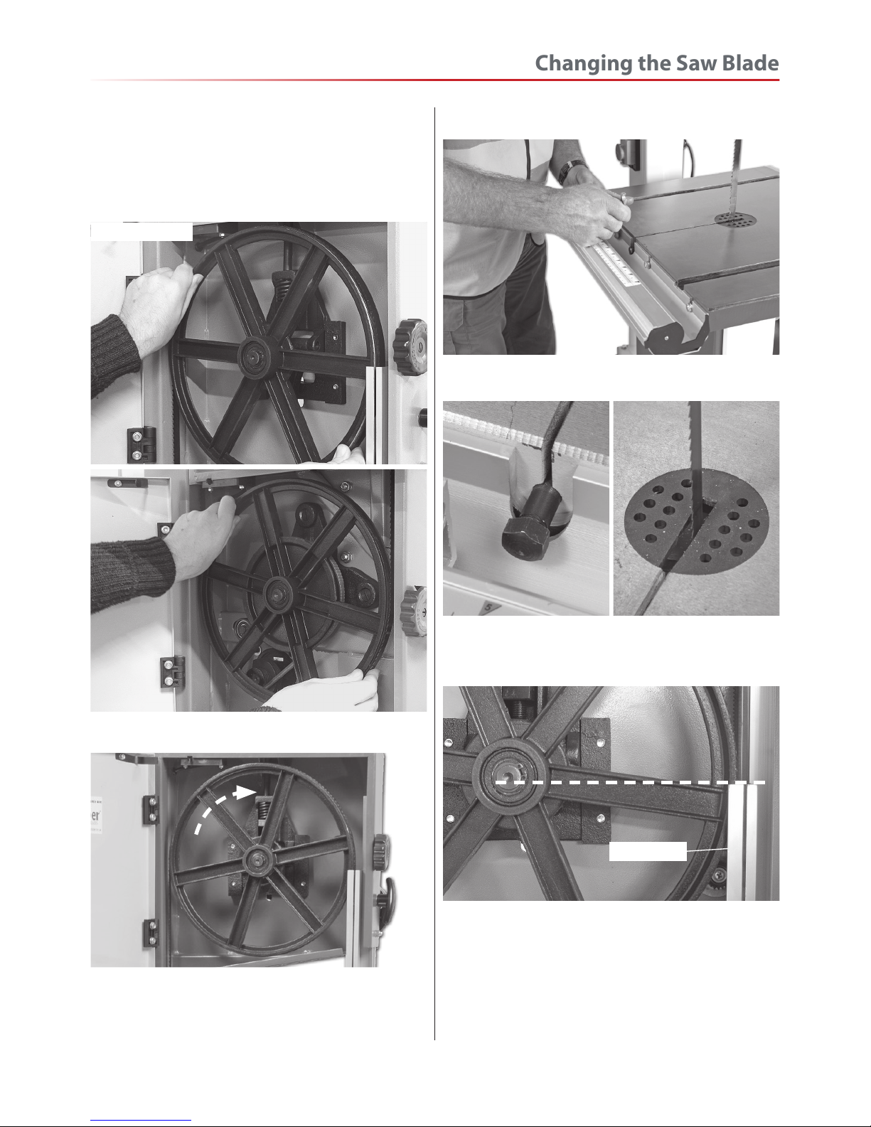
Fig 21-22
Fig 23
Fig 24
Fig 25-26
Stabilising bolt Table insert
Fig 27
Loosen the upper blade guide clamp and set the
upper blade guide assembly so that the top of the
blade guide is level with the centre of the top drive
wheel, see fig 27. Re-tighten the clamp. Fit the fence
assembly and carry out the procedures as detailed in
“Setting Up the Saw”.
Turn the top wheel by hand to ensure the blade will
not skip off the wheels and the blade is travelling in
the blade guides.
Changing the Saw Blade
21
Blade guide
Fitting the blade
wheel by hand. When you are sure that the blade is
“ON” and stable, re-fit the fence guide rail (see fig 24)
re-fit the stabilising bolt and re-fit the table insert
(see 25-26).
Page 22
DISCONNECT THE SAW
FROM THE MAINS SUPPLY!
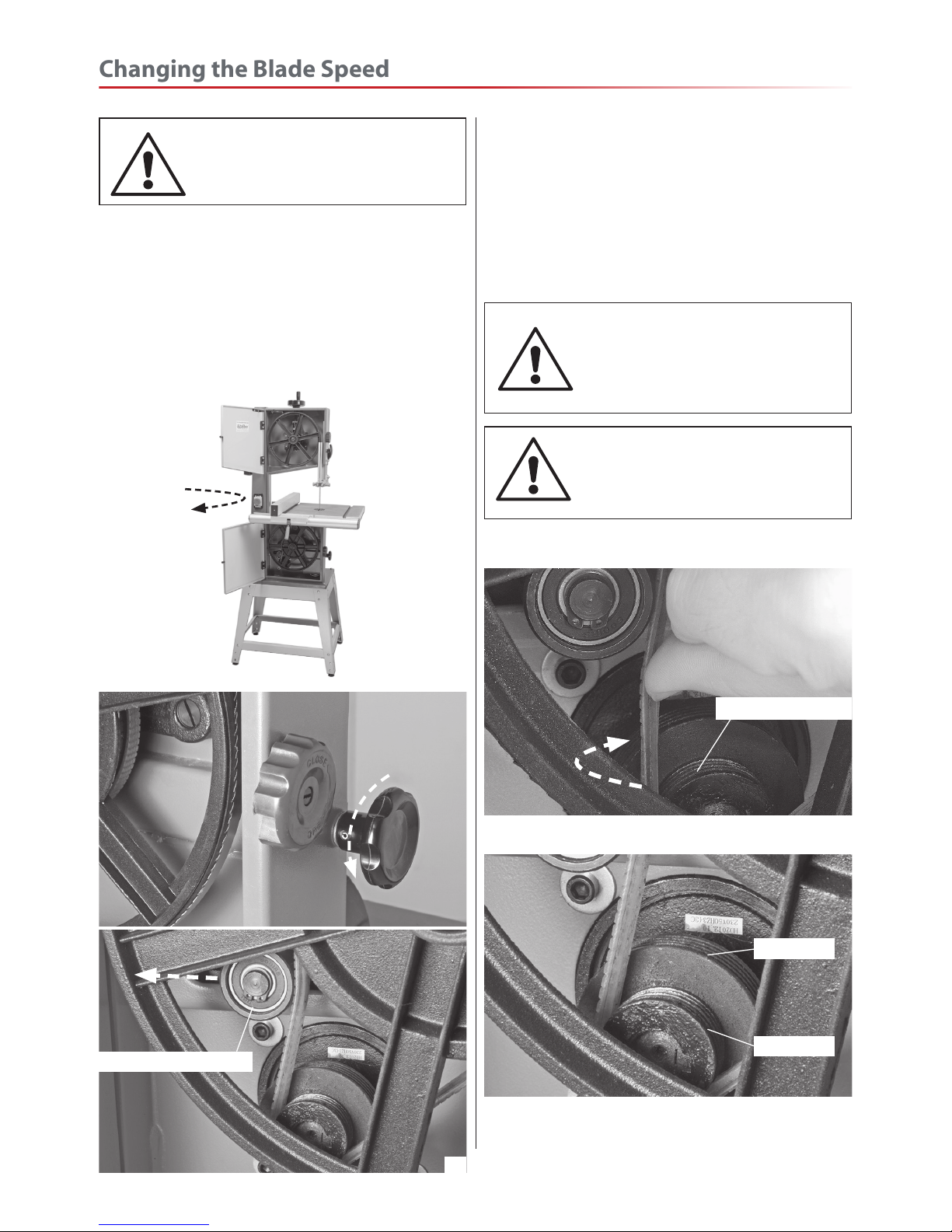
The bandsaw drive pulley has two speed positions
(see fig 52). To change the speed from 360 to
720m/minute, follow the instructions below.
Open the upper and lower doors, see fig 28. Release
the tension on the drive belt by turning the idler
wheel adjusting knob anti-clockwise, thus moving the
Fig 28
Fig 29-30
idler wheel back, see figs 29-30. With the drive belt
tension removed, very carefully reposition the drive
belt (see fig 31). NOTE: Make sure the belt is seated
correctly in one of the drive pulley grooves. With
the belt repositioned, turn the idler wheel adjusting
knob clockwise to re-tension the belt, enough to
prevent the belt from slipping when in operation,
but not tight to cause the belt to get hot.
WARNING! BE VERY CAREFUL
WHEN MOVING THE BELT NOT
TO TRAP YOUR FINGERS!
NOTE: MAKE SUE THE DRIVE BELT
IS NOT TENSIONED TO TIGHTLY
WHICH WILL CAUSE THE BELT TO
GET HOT.
Idler tensioning wheel
Changing the Blade Speed
22
Fig 31
Drive pulley groove
360m/min
720m/min
The picture above shows the two drive pulley
positions with the speeds available.
Page 23
Optional Wheel Mobility Kit
23
Optional Wheel Mobility Kit (508207)
The optional wheel kit provides mobility for the
Hobby bandsaw. To assemble follow the instructions
below:
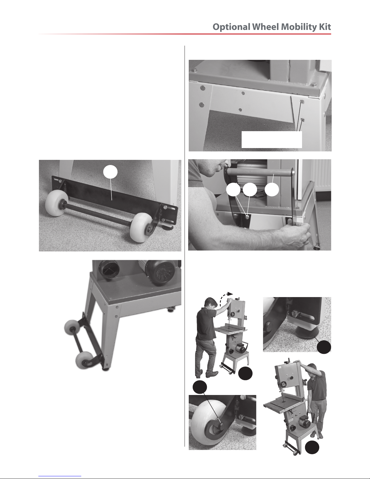
Step 1 Locate the wheel mobility assembly (J), four
M6 bolt, nuts, washers and lifting handle bracket
(K). Lineup the slotted holes in the mobility wheel
bracket (J) with the four slotted holes in the two front
leg supports and secure using the M6 bolts, nuts and
washers (see figs 32-33).
Fig 32-33
J
Step 2 Locate the lifting handle bracket (K) and two
M8 coach bolts,nuts and washers (G-H). Remove the
two coach bolts from the right support leg to the
rear of the stand assembly, place safely aside (see fig
34). Line up the four holes in the handle bracket (K)
with the four holes in the stand assembly and secure
in place using the four coach bolts, nuts and washers
(G-H), this includes the coach bolts you removed
earlier. (See figs 34-35)
Fig 34-35
Removed coach bolts
from the support leg
KE G
• Lift up the saw (a)
• Push wheels in to engage the up position (b)
and lower the bandsaw.
• Bandsaw feet is now raised of the ground (c)
• Bandsaw being moved to a new location (d)
b
a
c
d
Page 24
Routine Maintenance
24
Daily
• Keep the machine clean.
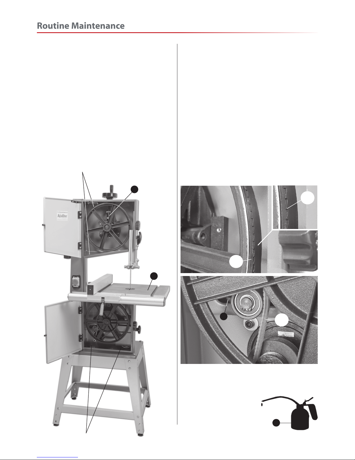
• Check the saw blade for missing teeth and
cracks (see fig 36).
• Spray oil the bare metal surfaces.
Weekly
• Open the top & bottom wheel covers and clean out
all saw dust.
Clean out impacted ‘crud’ & saw dust
Clean out impacted ‘crud’ and saw dust
Monthly
• Open the lower and upper door and check the
condition of the tyres and the drive belt (see figs
36-37).
• Clean impacted ‘crud’ from the tyres, apply a little
oil to the screw threads of the blade and drive belt
tensioners. DO NOT USE OIL near the belt.
• The pivots and the slides of the top wheel mounting
assembly and the captive stub axle of the belt
tensioner in its slot could likewise be lightly oiled.
• Using an air line (wearing goggles) blow out the
motor casing.
Fig 36-37
• Check for missing teeth (a)
• Check the condition of the tyres (b)
• Check the condition of the drive belt (c)
a
b
c
Oil
Page 25
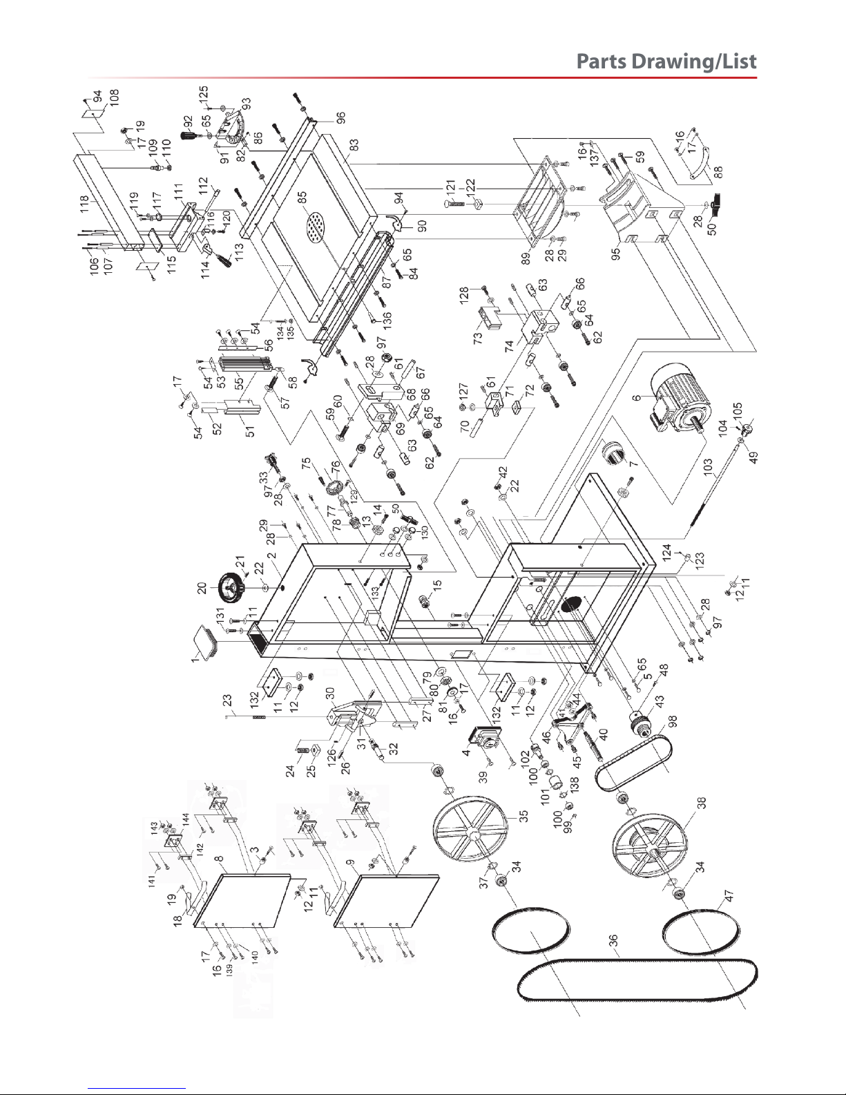
Continues Over...
Parts Drawing/List
25
Page 26
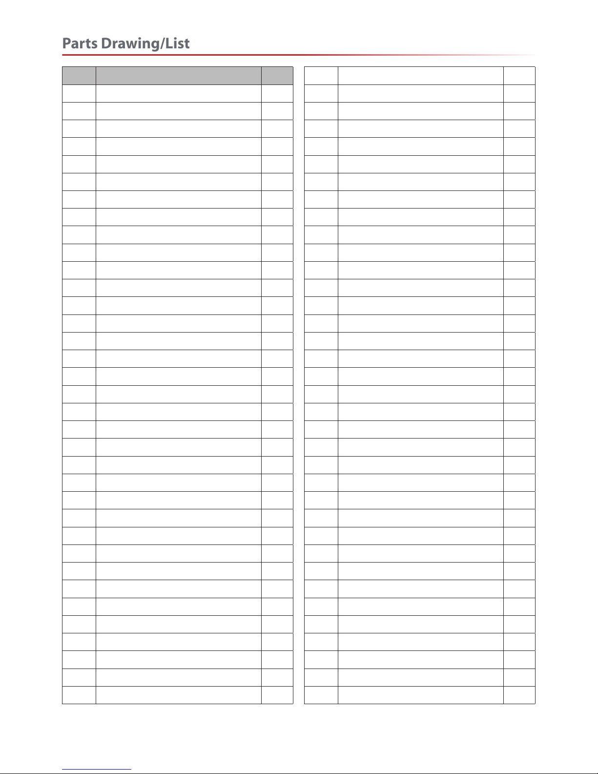
NO. Description Q’TY
1 Column cover 1
2 Saw body 1
3 Bush 2
4 Magnetic switch 1
5 Hexagon head screw M6×16 4
6 Motor 1
7 Dust cover 1
8 Upper door 1
9 Lower door 1
10 Screw 2
11 Washer ø4 15
12 Hexagon nut M4 8
13 Knob 2
14 Screw 2
15 Retainer 1
16 Semicircle head screw M5×8 6
17 Washer ø5 12
18 Spring leaf 2
19 Hexagon nut M5 3
20 Hand wheel 1
21 Screw 1
22 Washer ø12 4
23 Guide screw pole 1
24 Spring 1
25 Square nut 1
26 Steel dowel 2
27 Guide board saddle 2
28 Washer ø8 16
29 Hexagon head screw M8×16 8
30 Upper wheel saddle 1
31 Small triangular frame 1
32 Upper wheel axle 1
33 Adjusting handle M8 1
34 Bearing 80203 4
35 Upper saw wheel 1
36 Blade 1
37 Axis elastic ring 4
38 Lower saw wheel 1
39 Semicircle head screw M4×12 2
40 Lower wheel axle 1
41 Hexagon nut M16 1
42 Hexagon nut M12 3
43 Motor wheel 1
44 Washer ø16 1
45 Adjusting screw 3
46 Big triangle frame 1
47 Rubber belt for saw wheel 2
48 Screw 1
49 Washer ø10 1
50 Butterfly nut M8 2
51 Upper blade guard 1
52 Sliding plate 1
53 Spacing board 1
54 Tapping screw 7
55 Connecting board 1
56 Rack 1
57 Carriage bolt M8×25 1
58 Locking plate 1
59 Carriage bolt M8×20 5
60 Locking plate 1
61 Screw M6×6 6
62 Cap screw 6
63 Mount shaft 2
64 Bearing 80026 6
65 Washer ø6 24
66 Adjusting shaft 4
67 Upper guide shaft 1
68 Connecting bracket 1
69 Upper guide base 1
70 Lower guide shaft 1
71 Connecting base 1
Parts Drawing/List
26
Page 27
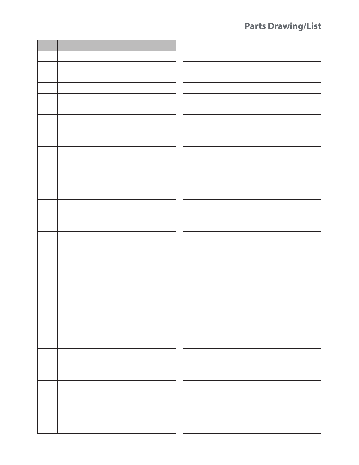
NO. Description Q’TY
72 Fixing plate 1
73 Lower blade guard 1
74 Lower guide base 1
75 Small handle 1
76 Hand wheel 1
77 Eccentric shaft 1
78 Eccentric bush 1
79 Washer ø22 1
80 Hexagon nut M22
81 Gear 1
82 Guide plate 1
83 Worktable 1
84 Cap screw M6×12 8
85 Table insert 1
86 Screw 1
87 Front fence rail 1
88 Rotating angle rule 1
89 Stand of worktable 1
90 Side insert 2
91 Pointer 1
92 Big handle 1
93 Mitre gauge 1
94 Tapping screw 4
95 Rolling fixed frame 1
96 Rear fence rail 1
97 Hexagon nut M8 6
98 Drawing belt 1
99 Circles for shaft 1
100 Bearing 80101 2
101 Press wheel 1
102 Axle of press wheel 1
103 Press wheel pole 1
104 Screw 1
105 Handle of press wheel
106 Cap screw M6×65 4
107 Bush 4
108 Side insert 2
109 Bearing bar 1
110 Bearing 80027 1
111 Sliding base 1
112 Shaft 1
113 Locking handle 1
114 Locking block 1
115 Plate 1
116 Spring piece 1
117 Convex window 1
118 Upper guide board 1
119 Semicircle head screw M4×5 2
120 Semicircle head screw M4×8 1
121 Carriage bolt M8×50 1
122 Plastic square washer 1
123 Fix bush 1
124 Screw M6×12 1
125 Semicircle head screw M6×6 1
126 Screw 1
127 Hexagon nut M6 1
128 Semicircle head screw M5×14 1
129 Screw 1
130 Lid shape nut 2
131 Semicircle head screw M4×30 4
132 Safety switch 2
133 Semicircle head screw M6×8 2
134 Hexagon head screw M8×25 1
135 Rubber washer 1
136 Pin 1
137 Pointer 1
138 Ring 2
139 Semicircle head screw M6×20 8
140 Washer ø6 16
141 Countersunk head screws M6X16 8
142 Hinge plate 4
143 Nut M6 8
144 Hinge 4
Parts Drawing/List
27
Page 28
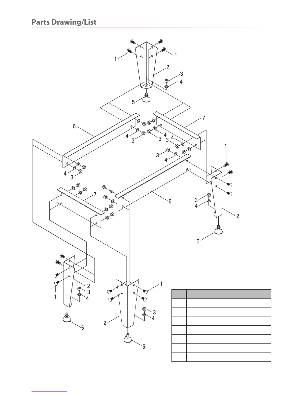
NO. Description Q’TY
1 Hex bolt M8X16 16
2 Support parts 4
3 Nut M8 20
4 Washer ø8 20
5 Rubber legs M8X15 4
6 Connected plate (1) 2
7 Connected plate (2) 2
Parts Drawing/List
28
Page 29
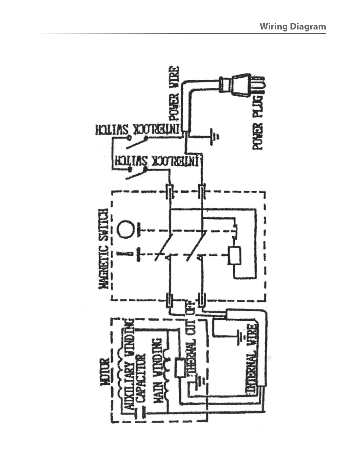
Wiring Diagram
29
Page 30

Blades/Accessories
30
Standard Axcaliber Bandsaw Blades
Axcaliber Ground Tooth Bandsaw Blades
Axcaliber GT bandsaw blades are made from a high
carbon content steel band with diamond ground
teeth. This gives a much higher level of accuracy in
the tooth formation, plus they stay sharp for at least
30% longer than normal, milled tooth blades. The
result is a smoother cut for much longer, a really
useful step forward for bandsaw blades.
An optional wheel kit to provide mobility for the
Axminster Hobby Series HBS310N and HBS350N
bandsaws. Includes a bolt-on handle for the bandsaw
frame.
HBS310 & 350N Mobility Kit 508207
Code
Axminster Hobby Series HBS310 & 350N Wheel Kit
Axminster HBS310N Bandsaw
4 skip 1/4” 211533
6 skip 1/4” 211534
14 reg 1/4” 211537
4 skip 3/8” 211538
6 skip 3/8” 211539
10 reg 1/4” 211540
10 reg 3/8” 211541
14 reg 3/8” 211542
24 reg 3/8” 211543
4 skip 1/2” 211544
6 skip 1/2” 211545
10 reg 1/2” 211546
14 reg 1/2” 211547
24 reg 1/2” 211548
TPI Width Code
2,270mm(89”) x 0.025”
6 1/4” 505260
10 1/4” 505261
4 3/8” 505262
6 3/8” 505263
10 3/8” 505264
3 1/2” 505265
4 1/2” 505266
6 1/2” 505267
10 1/2” 505268
3 3/4” 505269
4 3/4” 505270
TPI Width Code
2,270mm(89”)
Page 31

Notes
31
Page 32

Axminster Tools & Machinery Ltd
Weycroft Avenue, Axminster, Devon EX13 5PH
axminster.co.uk
Please dispose of packaging for the product in a responsible manner. It is suitable for recycling.
Help to protect the environment, take the packaging to the local recycling centre and place into
the appropriate recycling bin.
Do not dispose of electric tools together with household waste material. In observance of
European Directive 2002/96/EC on waste electrical and electronic equipment and its
implementation in accordance with national law, electric tools that have reached the end of their
life must be collected separately and returned to an environmentally compatible recycling facility.
Only for EU countries
The Axminster guarantee is available on
Hobby, Trade, Industrial, Engineer, Air Tool & CNC Technology Series machines
It’s probably the most comprehensive FREE guarantee ever- buy with confidence from Axminster!
So sure are we of the quality, we cover all parts and labour free of charge for three years!
• Look for the icon and put your trust in Axminster
• No registration necessary - just keep your proof of purchase
• Optional Service Plan for Industrial Series machinery
Great value & easy-to-use,
perfect for use at home
Solid, reliable machines
designed for daily use
Top performers with class leading features and
build quality for use in busy workshops
Quality, precision machines
for the workshop or education
Precision CNC machines for
industry and education
Small machines for the home
engineer
Tools for home or workshop
use; durable and great value
Free Three Year Guarantee on Axminster Hobby, Trade and Industrial Series
woodworking and engineering machines, Axminster Air compressors and Air
Tools, and bench top grinders - no registration necessary just proof of purchase.
We will repair or replace at our discretion and will collect only from a UK
mainland address, irrespective of the original delivery address.
The Guarantee assumes that you have bought the correct machine for the
required operation, in accordance with our guidelines; have operated and
maintained it in accordance with the instruction manual; and that all cutting
machines will be used with a blade which is sharp and serviceable at all times.
It does not cover consumable items purchased with the original product,
including original blades or abrasives.
Normal wear and tear, misuse, abuse and neglect are excluded and the machine
should not have been modified in any way. Please do not attempt to service the
product without first contacting us; we are happy to guide you but failure to do
so may invalidate the guarantee.
The Guarantee is transferable from owner to owner in the first three years but
you must have original proof of purchase. Should we need to replace a machine
in the first three years the guarantee will still continue to be effective from the
original purchase date.
Full Terms and Conditions can be found at axminster.co.uk/terms
This guarantee does not affect your statutory rights.
For more information visit axminster.co.uk/3years
 Loading...