

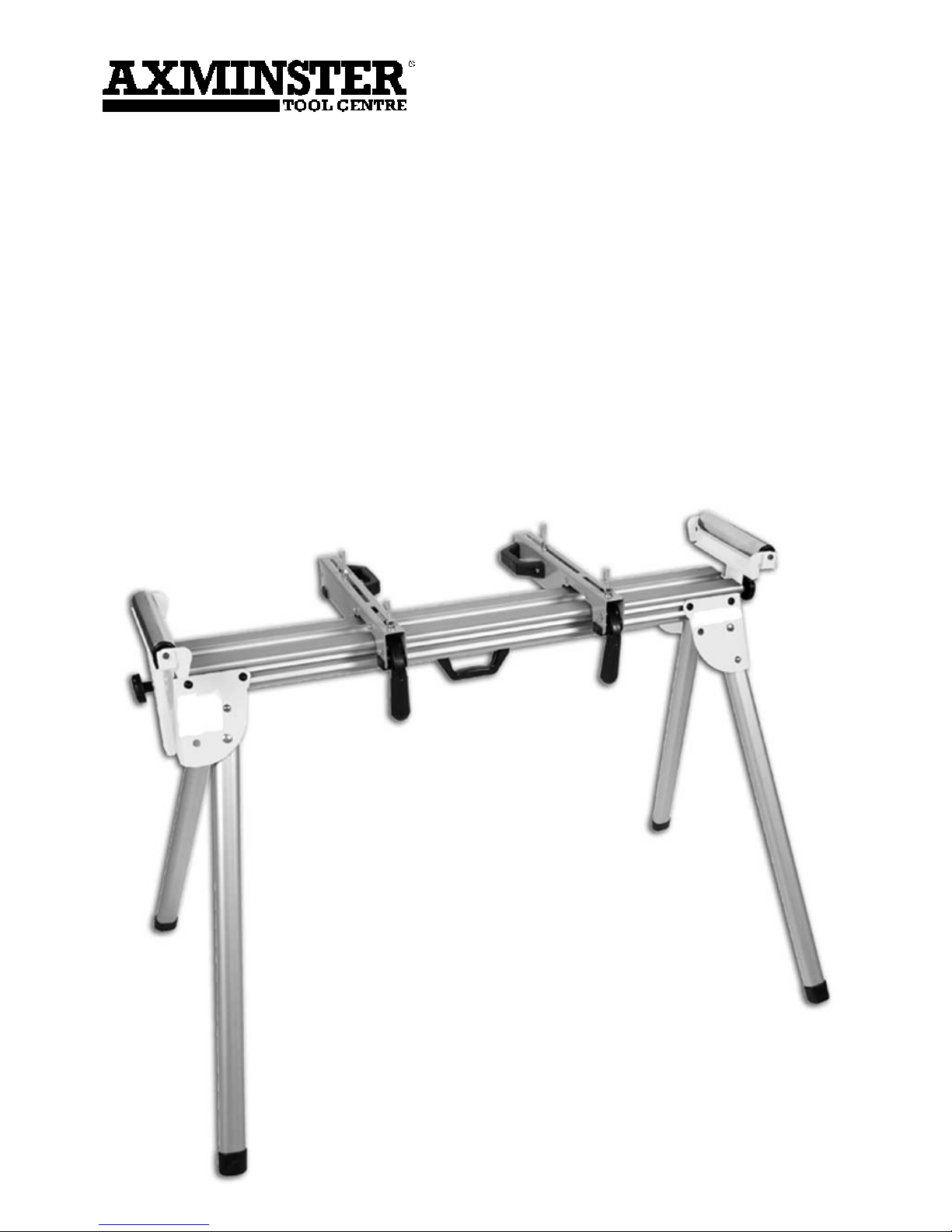
Deluxe
Mitre Saw Stand
Code 211518

Index of Contents
Page No
1 No. Del uxe Mitre Saw Stand A
2 No. Saw Mounting Rails B
1 No. Instruction Manual
Specification
Code 211518
Folded: L 1160mm x W 280mm x H 285mm
Assembled and Extended: L 2840mm x W 780mm x H 1010mm
Length of Mounting Rails: 415mm
02
Index of Contents 02
Specification 02
What’s in the Box 02-03
Safety Instructions 03
Assembly Instructions 04-05-06
Illustration & Description 07
Extending the Roller Assembly 08
Raise & Lower the Roller Assembly 09
Roller Assembly Work Stop 09
Mounting the Mitre Saw 10-11
What’s in the Box
Warning
The symbols below advise that you follow the correct
safety procedures when using this machine.
Dust mask
should be worn
Ear protection
should be worn
Eye protection
should be worn
Fully read manual
and safety instructions
before use

Only use the mitre saw stand on a flat and level surface.
Ensure that all four legs are fully extended and the spring pins are locked in position.
Make sure the mitre saw is correctly located on the stand and firmly secured in position.
Carefully read and follow all the safety instructions for your mitre saw before starting
work.
03
What’s in the Box
A
B
The following suggestions will enable you to observe good working practices, keep yourself and
fellow workers safe and maintain your tools and equipment in good working order.
Good Working Practices/Safety
WARNING!!
!
KEEP TOOLS AND EQUIPMENT OUT
OF THE REACH OF YOUNG CHILDREN
Please unpack the components of your mitre saw stand & check each item against “What’s in the
Box” list. If any item is missing please contact our customer service department using the phone
number on the back cover. Having unpacked your saw stand & its accessories please dispose of
any unwanted packaging properly. The packaging is biodegradable.
Safety Instructions

04
Assembly Instructions
(Step 1) Place the stand (A) in the inverted position, push and hold the spring pin in and rotate
the leg to its fully extended position, checking that when the leg is extended the spring pin
re-engages the pre-drilled hole in the frame to lock it in position. Repeat for the remaining legs.
(Step 2) Turn the stand (A) to the upright position.
(Step 3) Locate one of the two mounting rails (B). Lift the locking lever so it is in the horizontal
position, lower the mounting rail, so it engages over the sides of mitre saw stand rail (A) and
push the locking lever down to lock it in position.
Stand fully assembled.
Spring pin
Spring pin locked
in position
Step 1
A

05
Assembly Instructions
Step 2
Step 1
Support legs
Turn stand (A) upright
A

Lock
06
Assembly Instructions
B
A
Push the locking handle down to lock
the saw mounting rail in position
Lower the saw mounting rail (B) over
the mitre saw stand rail (A)
Step 3
Locking handle
Un-lock

07
Illustration & Description
Roller
Fence
Carrying handle
Clamping handle
Saw mounting rails
Mitre saw stand rail
Leg
Roller rise &
full locking
knob
Carrying the mitre saw stand

08
Extending the Roller Assembly
To extend the roller assembly
follow the instruction below.
1. Push the roller lever lock (C)
down to un-lock the roller
assembly.
2. Hold the roller assembly (D)
and pull towards you.
3. Pull the roller lever lock (C)
back up to secure the roller
assembly in position.
C
C
D

09
Raise & Lower the Roller Assembly
Roller Assembly Work Stop
To raise or lower the height of the roller assembly, simply undo the clamping knob (E) until the
assembly is loose, adjust the height and then re-tighten the clamping knob (E) to secure it in
position.
E
The roller assembly has a hinged work stop which can be raised or lowered when needed.
See figs F, G & H below.
F
G
H
Timber
Raise the work stop in position Work stop raised Timber up against work stop

10
Mounting the Mitre Saw
B
Approx width of your mitre saw
WARNING!!
!
MAKE SURE THE LEGS FOR THE STAND ARE
LOCKED IN PLACE BEFORE MOUNTING THE
MITRE SAW ON THE STAND.
1). Set the saw mounting rails (B) to the approx width of your mitre saw.
2). Undo and remove the four M8 nuts, washers & spring washers.
3). Line up the four M8x50mm bolts (I) with the pre-drilled holes in your mitre saw and very
carefully lower the mitre saw onto the rails.
4). Using the nuts, washers & spring washers (J) you removed earlier, secure the mitre saw in
place using a 13mm spanner. When the mitre saw is seated on the mounting rails the whole
assembly can be positioned where required and locked in place.

11
Mounting the Mitre Saw
I
I
J
B

Axminster Tool Centre,
Unit 10 Weycroft Avenue, Axminster, Devon EX13 5PH
axminster.co.uk
 Loading...