

Page 1
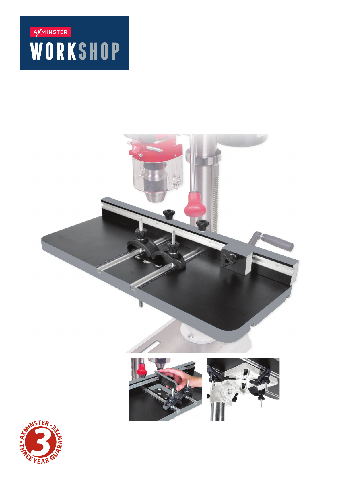
Drill Press Table
Code 109540
Original Instructions
AT: 31/05/2023
BOOK VERSION:
01
• Universal design, fits a wide range of drill presses.
• Large work surface for greater support.
• Adjustable fence and sliding stop block for repeat
drilling.
• Table Dimensions: 605mm x 300mm
• Fence Dimensions: 600mm x 50mm
• Drill Press Table Thickness: 25mm
• T-Track Centre to Centre: 108mm
Removable insert allows you to
drill completely through the
workpiece without damaging
the table.
The table comes with five clamps
in total, three for use on the
underside and two for use as
work holding clamps on the top.
Page 2
Keep this manual available to all users during the entire life of the tool and review it
frequently to maximize safety for both yourself and others.
1. SPECIFICATION
:
Drill Press Table Thickness: 1 Inch
T-Track Center to Center Distance: 4-1/4 Inches
Ta bl e S iz e : 23-7/8 in. x 11-7/8 in.
Fence Size: 23-5/8 in. x 2 in.
Overall Size: 23-7/8 in. x 11-7/8 in. x 7-5/8 in.
Weight: 4.75kg
Read all safety warnings and all instructions. Failure to follow the warnings and
instructions may result in electric shock, fire or serious injury.
2. GENERAL SAFETY RULES
:
2.1 WORK AREA SAFETY
▲Keep work area clean and well lit. Cluttered or dark areas invite accidents.
▲Do not operate power tools in explosive atmospheres, such as in the presence of flammable liquids,
gases or dust. Power tools create sparks which may ignite the dust or fumes.
▲Keep children and bystanders away while operating a power tool. Distractions can cause you t
lose control.
o
2.2 PERSONAL SAFETY
▲Stay alert, watch what you are doing and use common sense when operating a power tool. Do not
use a power tool while you are tired or under the influence of drugs, alcohol or medication.
1
Page 3
▲Use personal protective equipment. Always wear eye protection. Protective equipment such as a
respiratory mask, non-skid safety shoes and hearing protection used for appropriate conditions will
reduce the risk of personal injury.
▲Prevent unintentional starting. Ensure the switch is in the off-position before connecting to power
source and/or battery pack, picking up or carrying the tool.
▲Remove any adjusting key or wrench before turning the power tool on. A wrench or a key le
attached to a rotating part of the power tool may result in personal injury.
2.3 ELECTRICAL SAFETY
▲Power tool plugs must match the outlet. Never modify the plug in any way. Do not us e any ad apter
plugs with earthed (grounded) power tools. Unmodified plugs and matching outlets will reduce risk of
electric shock.
▲Avoid body contact with earthed or grounded surfaces such as pipes, radiators, ranges and
refrigerators. There is an increased risk of electric shock if your body is earthed or grounded.
▲Do not expose power tools to rain or wet conditions. Water entering a power tool will increase the
risk of electric shock.
▲Do not abuse the cord. Never use the cord for carrying, pulling or unplugging the power tool. K
eep
cord away from heat, oil, sharp edges or moving parts. Damaged or entangled cords increase the risk
of electric shock.
▲When operating a power tool outdoors, use an extension cord suitable for outdoor use. Use of a
cord suitable for outdoor use reduces the risk of electric shock.
ft
3. ASSEMBLY & ADJUSTMENTS
3.1 INSTALLATION ON TABLES WITH THROUGH SLOTS
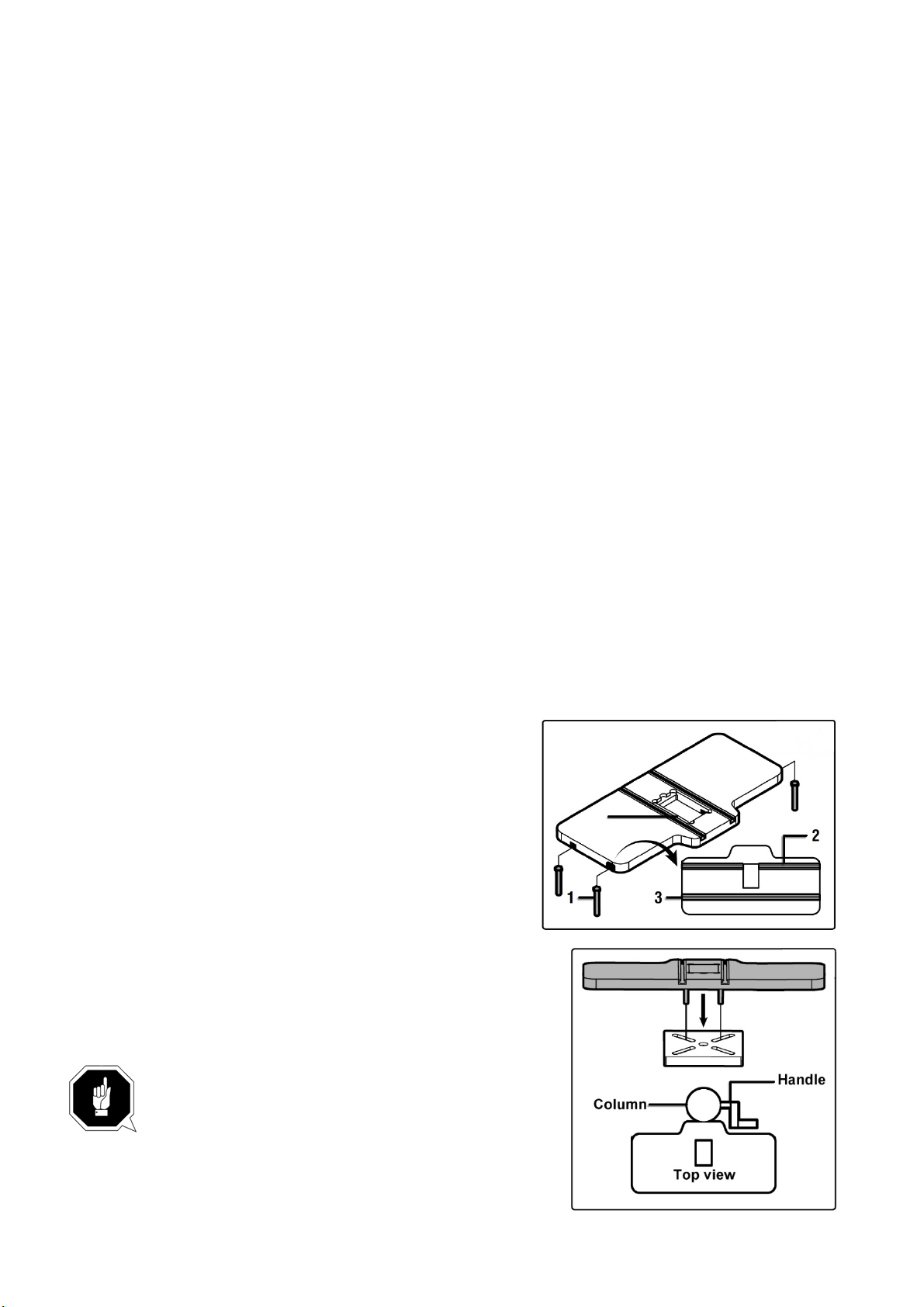
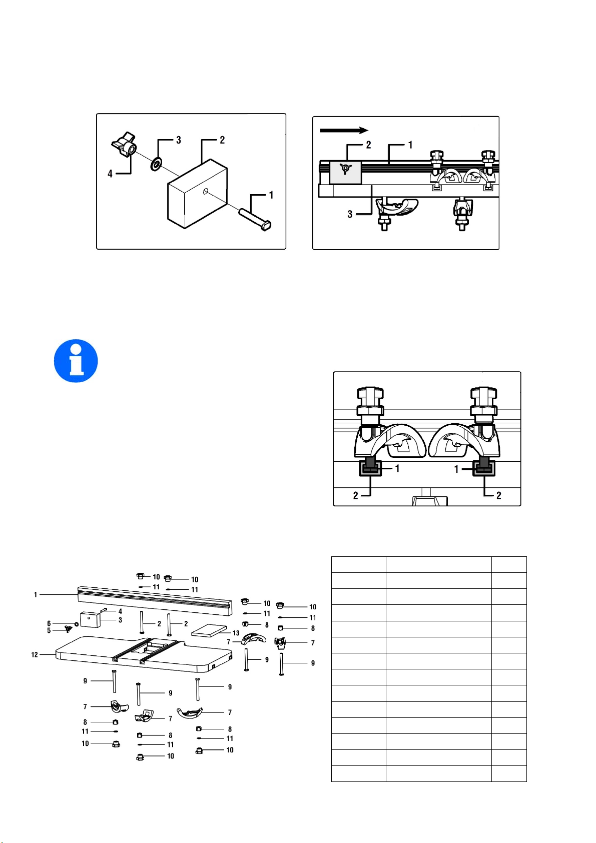
1. Slide the heads of the M8x90 bolts (part 1) into the
back T-track (part 2), one on each side, and slide one int
o
the front T-track (part 3), if desired.
2. Position the bolts in the back T-track such that they fi
t
through the slots on the metal drill press table. Place them
through the slots. Position the table so that the front bolt is
lined up with the front of the table, or passes through a slot or
hole in the metal table, depending on your drill press model.
NOTE: When installing the drill press table onto
the drill press, make sure that the narrow end is
against the drill press column as shown. This
will allow room for the handle to rotate freely.
2
Page 4
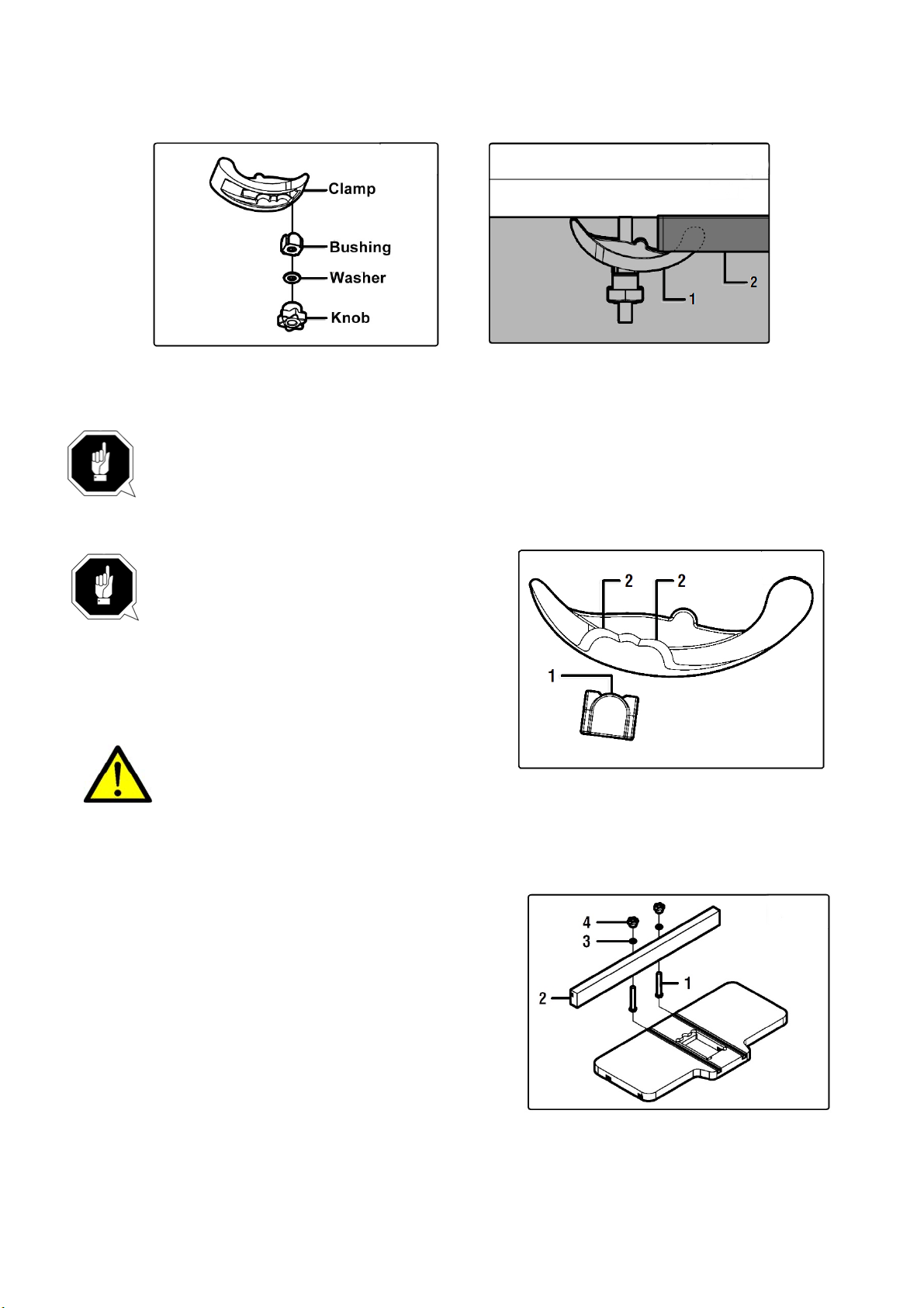
3. Attach the clamp assemblies to the bolts in the following order: Clamp, clamp bushing, washer,
knob.
4. Tighten the knobs on the clamp assemblies. Make sure that the drill press table is properly
aligned and centered before the knobs are fully tightened.
NOTE: For the most secure clamping, have the clamps resting against a flat surface
underneath the table. If the front clamp assembly is not placed through a slotted
hole, have the rounded end of the clamp, gripping the front lip of the metal drill
press table.
NOTE: To ensure the clamps are locked
into place properly, check that the clamp
bushings are properly seated into the
clamps. The rounded tops of the bushings
(part 1) should mate with one of the rounded
grooves in the clamps (part 2). Once the clamps
are properly seated, fully tighten the knobs.
Regularly check that the mounting
clamps are secure. After each operation,
wipe the drill press table clean and vacuum out the T-slots to keep the tool in good
condition. To avoid condensation and rust between the two tables, do not leave the drill
press table mounted on the drill press for long periods of time.
3.2 ASSEMBLING THE FENCE
1. Place the M8x70 half threaded bolt (part 1) up
through the bottom of the fence (part 2) and secure
loosely with a washer (part 3) and knob (part 4).
NOTE: The fence should be positioned with the Ttrack towards the top.
2. Align the bolt heads with the top T-track on the table.
Slide the fence onto the table. Position the fence to the
desired position and lock it into place by fully tightening
the knobs (part 6).
TIP: Turn the feed handles on the drill press to check if the fence will interfere with the
handles. One or two of the feed handles may be removed if the fence is in the way of the feed
handle’s travel.
3
Page 5
3.3 ASSEMBLING THE STOP BLOCK
Part No.
Description
Qty
1
Fence
1
2
Bolt M8x70
2
3
Stop Block
1
4
Bolt M6x40
1
5
Triangle Knob
1
6
Washer 6x18x1.2
1
7
Clamp
5
8
Clamp Bushing
5
9
Bolt M8x90
5
10
Flower Knob
7
11
Washer 8x20x1.5
7
12
Ta bl e
1
13
Ta bl e I ns e rt
1
1. Place the M6x40 bolt (part 1) though the stop block (part 2) and washer (part 3). Loosely thread
the stop block knob (part 4) onto the bolt.
2. Slide the bolt through the T track on the fence (part 1) such that the bottom of the stop block (pa
2) lies against the top of the table (part 3).
3. Slide the stop block to the desired position and lock it in place by fully tightening the knob.
3.4 ASSEMBLING THE HOLD DOWN CLAMPS
The drill press table comes with two hold down clamps, which can be used to clamp
down a workpiece to the drill press table.
1. Assemble the hold down clamps in the same order
as the clamp assemblies under the table.
2. Slide the bolts of the hold down clamps ( part1) int
o
the top T-slots on top of the table (part 2).
3. Place the workpiece on the drill press table
and
clamp it down by tightening the knobs. Make sure the
clamp bushings are seated properly in the clamps.
4. DIAGRAM AND PART LIST
rt
4
Page 6
The Axminster guarantee
Buy with confidence from Axminster Tools!
So sure are we of the quality, we cover all parts and labour free of charge for three years!
For more information visit axminstertools.com/3years
The packaging is suitable for recycling.
Please dispose of it in a responsible manner.
EU Countries Only
Do not dispose of electric tools together with household waste material.
By law they must be collected and recycled separately.
Axminster Tools, Axminster Devon EX13 5PH
axminstertools.com
 Loading...