

Page 1
Code 103738
Original Instructions
1
SUPPORT BAR
WITH DUAL AXIS
ADJUSTMENT
Terminology of the Support Bar
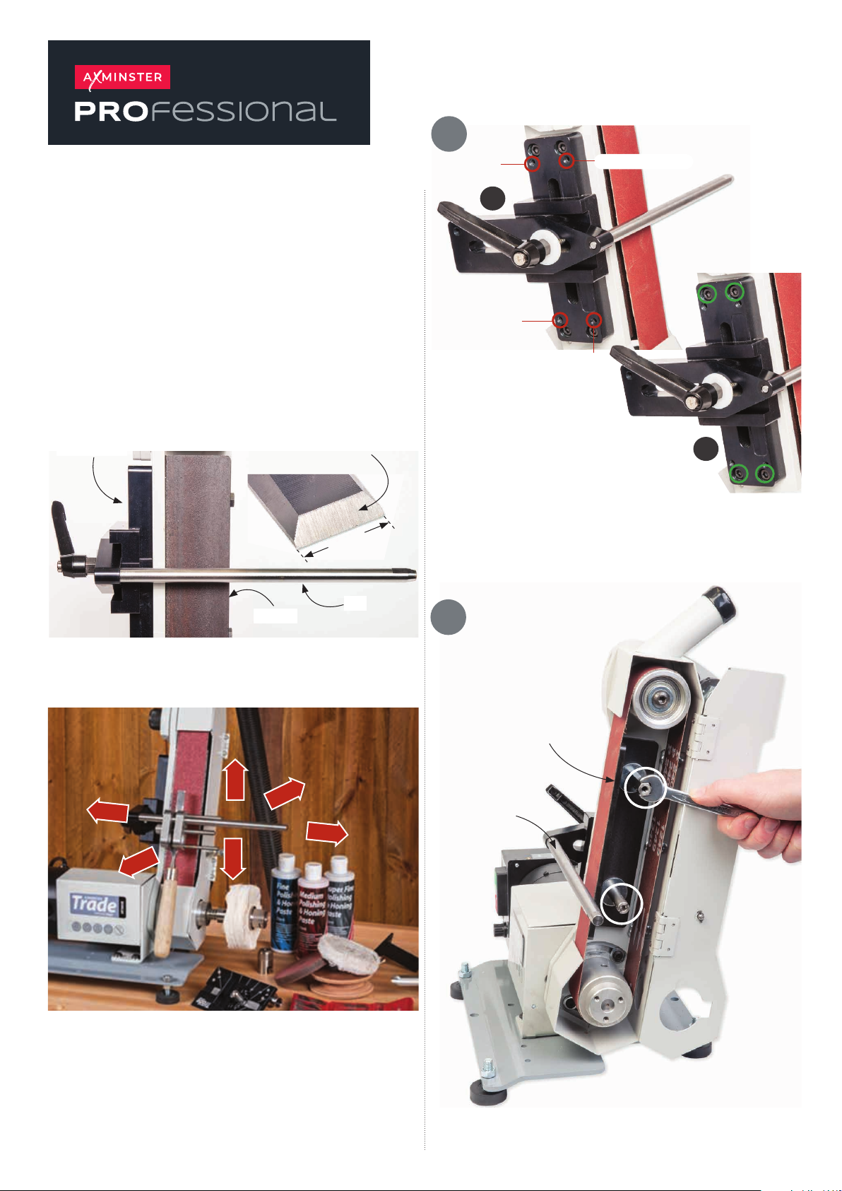
These are the striations,
we call them sharpening lines
Support Bar
25mm
Grub screw A
Grub screw B
A
Grub screw C
Grub screw D
The ‘RED’ circles in figure (A) shows the
positions of the grub screws used to adjust
the support bar, to the side of the frame. The
‘GREEN’ circles in figure (B) shows the
position of the Hex head screws used to fix
the support bar to the side of the linisher.
B
Left
Front
Up
Down
Platen
Back
Bar
Right
Setting the Jig
2
Loosen the two studs
Bar
Continues Over...
Page 2
3
Platen
4
Loosen the two threaded studs holding the platen. Adjust the
platen so it projects out from the steel frame of about 0.5 to
1mm. Tighten the studs to secure the platen in place.
Setting the Bar to the Platen
Method One Method Two
Steel frame
0.5 to 1mm
Clearance
Setting the Bar at 90˚ to the Platen
Linisher
Bar
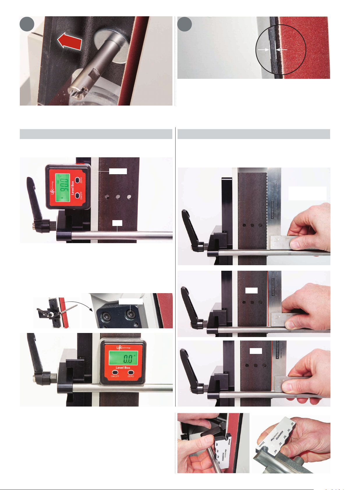
Using a digital leveling box check the suport bar is perpendicular
to the platen. Place the leveling box onto the bar, it should read
‘ZERO’ on the display. If adjustment is required, lightly loosen the
four Hex screws and adjust the support bar until the ‘Bar’ is in
line with the platen, nip up the Hex screws to secure the
assembly.
Hex screw
Alternatively place a 90˚ square on the bar and check its in line
with the edge of the platen and make adjustments accordantly.
Square to the
platen
Gap
Ultimate Edge Angle Guage
The ‘Angle Gauge’ tool is a quick and easy way to accurately set
the correct clearence between the platen and the support bar.
The gauge has five preset stops from 20˚ to 40˚ degrees. The
gauge also incorporates a 25mm projection stop to set the
correct projection of the chisel out from the ‘Honing Guide’
assembly.
Gap
 Loading...