

Page 1
100247
Axminster’s
Super Precision
Woodturning
Chuck
User Manual
www.axminster.co.uk
Page 2
The Axminster Skill Centre is based within the Axminster Tool Centre retail
store and is fitted out with an extensive range of tools and machinery. Our
courses are run by experienced tutors who offer students a wealth of
knowledge, experience and enthusiasm. For full details of our increased
range of courses and availability, contact us on 0800 9751905 or
alternatively visit our website www.axminsterskillcentre.co.uk
Index of Contents...
Page No.
Safety Protection Symbols
SAFETY!!
!
The symbols shown on the cover of this
manual advise you to observe the appropriate
safety protocols when using this machine.
E
y
e
P
r
o
t
e
c
t
i
o
n
S
a
f
e
t
y
H
e
l
m
e
t
P
r
o
t
e
c
t
i
v
e
G
l
o
v
e
s
S
a
f
e
t
y
F
o
o
t
w
e
a
r
R
e
s
p
i
r
a
t
o
r
S
a
f
e
t
y
V
i
s
o
r
R
e
a
d
M
a
n
u
a
l
T
w
o
M
a
n
A
s
s
e
m
b
l
y
E
a
r
D
e
f
e
n
d
e
r
s
D
u
s
t
M
a
s
k
02
Index of Contents..................................................................................................................02
What’s in the Box………….………........……..………….........................................................03
Optional Accessories............................................................................................................04
Basic Safety for Machine Tools.......................................................................................05-06
Specific Safety Instructions for the Chuck...........................................................................06
Four Jaw Self Centring Chuck..............................................................................................07
Changing the Chuck Jaws.....................................................................08-09-10-11-12-13-14
Woodturning Chuck Jaws...................................................................... 15-16-17-18-19-20-21
Chuck Accessories.....................................................................................................20-21-22
Maintenance...........................................................................................................
22
Lathe Thread Information.....................................................................................................23
Parts Breakdown...................................................................................................................23
Right & Left Hand Threads Table..........................................................................Back Cover
Page 3
03
What’s in the Box...
Model Number: 100247
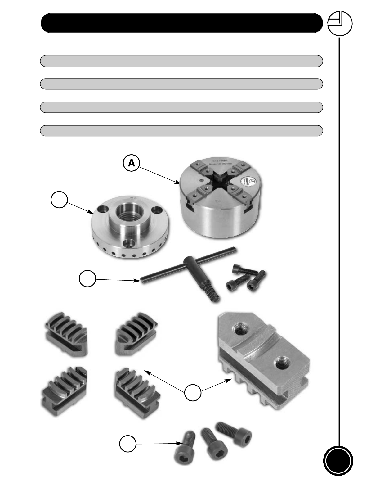
1 No. Super Precision Chuck with Mounting Jaws
1 No. Threaded Indexed Backplate, included in package
1 No. Chuck Key
4 No. Mounting Accessory Jaws
3 No. Caphead Screws
1 No. Instruction Manual
A
B
C
D
E
A
E
C
B
D
Page 4
04
Optional Accessories...
www.axminster.co.uk
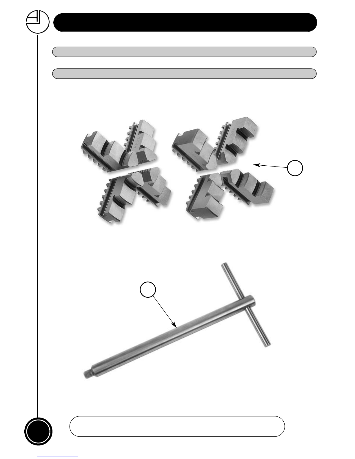
4 No. Internal & External Step Jaws Order No: 200038
1 No. Long Key (8mm2) Order No: 600121
F
G
F
G
Page 5
05
Basic Safety for Machine Tools...
The following suggestions will enable you to observe good working
practices, keep yourself and fellow workers safe and maintain your
tools and equipment in good working order.
Good Working Practices/Safety
WARNING!!
!
KEEP TOOLS AND EQUIPMENT OUT
OF THE REACH OF YOUNG CHILDREN
BASIC SAFETY FOR MACHINE TOOLS
KNOW YOUR MACHINE TOOL
Read and understand the owner's manual and labels affixed to the tool. Learn its application and
limitations as well as specific potential hazards peculiar to the tool.
EARTH ALL TOOLS
All machines should be equipped with an approved cable. The green and yellow conductor in the
cable is the earth wire and should be connected appropriately.
NEVER connect the green and yellow wire to a live terminal.
KEEP GUARDS IN PLACE
Keep all guards in place. They are there for your protection and do not interfere with the correct
operation of your machine.
REMOVE ADJUSTING KEYS AND WRENCHES
Form the habit of checking to see that keys and adjusting wrenches are removed from the machine
before turning it on.
KEEP WORK AREA CLEAN
Cluttered areas and benches invite accidents. Floors must not be slippery due to oil or sawdust. Make
sure you clean up any waste materials on completion of work.
AVOID DANGEROUS ENVIRONMENTS
Do not use power tools in damp or wet locations or expose them to rain. Keep work area well lit.
Provide adequate space surrounding the work area.
KEEP CHILDREN AWAY FROM WORK AREA UNLESS UNDER CLOSE SUPERVISION
All visitors should be kept a safe distance from work area. Children are naturally curious; therefore
ensure they are closely supervised when they are near the work area.
MAKE WORKSHOP TAMPER PROOF
Many machines have lockable switches that can be secured with a small padlock or have a removable
key. Please make use of them to prevent unauthorised operation of your machines.
DO NOT FORCE TOOL
It will do the job better and safer at the rate for which it was designed. Develop a patient approach to
the work, you will get better results in the finished product.
WEAR PROPER CLOTHING
Do not wear loose clothing, gloves, neckties or jewellery that can catch in moving parts of machinery.
Non-slip footwear with steel toecaps is recommended. Wear protective hair covering to contain long
hair. Roll up long sleeves to above the elbow.
SECURE WORK
Where applicable use clamps or a vice to hold work. This leaves both hands free to operate the tool
correctly and thus produces better results.
DIRECTION OF FEED
Feed work into a blade or cutter against the direction of rotation of the blade or cutter only. This will
reduce the danger of kick back which is a serious hazard. Similarly, when using a lathe feed the
cutting edge of the tool against the direction of rotation!
USE SAFETY GOGGLES AND FACE PROTECTION
Wear safety goggles (complying to relevant standards) at all times. Normal spectacles only have
impact resistant lenses and are NOT sufficient. Also use face or dust masks if the cutting operation is
dusty (connection of machine to a dust extractor is preferred). Always wear ear defenders for cutting,
sawing, planing or routing operations. Your hearing can be permanently damaged if exposed to high
noise levels for long periods of time.
Page 6
06
Basic Safety for Machine Tools...
DO NOT OVERREACH
Keep proper footing and balance at all times.
MAINTAIN TOOLS WITH CARE
Keep tools sharp and clean at all times for the best and safest performance. Follow the
manufacturer's instructions for lubricating and sharpening and also for changing
accessories.
DISCONNECT POWER FROM THE TOOL
Before servicing or when changing accessories always disconnect the power supply to
avoid accidental starting.
AVOID ACCIDENTAL START UP
Although most machines are now equiped with NVR switches develop the habit of making
sure the switch is in the "OFF" position before connecting the machine to the power supply.
USE RECOMMENDED ACCESSORIES
Consult the owner's manual for details of any manufacturer's accessories or contact your
supplier for details of recommended accessories. Follow the instructions that accompany
the accessory. The improper use of accessories may cause hazards. The fitting of
non-recommended accessories may also cause hazards.
CHECK DAMAGED PARTS
Before using the tool, a guard or other part that is damaged should be carefully
checked to ensure that it will operate properly and perform its intended function. Check
for alignment of moving parts, breakage of parts, mounting and any other conditions that
may affect its operation. A guard or other part that is damaged should be properly repaired
or replaced. A parts list is to be found at the back of your operator's manual.
NEVER LEAVE A MACHINE RUNNING UNATTENDED
ALWAYS turn power off. Do not leave machine until it comes to a complete stop.
DRUGS, ALCOHOL AND MEDICATION
NEVER operate tools whilst under the influence of drugs, alcohol or after taking medication.
USE THE CORRECT TOOL
Do not force a tool or attachment to do a job for which it was not designed. This is
dangerous workshop practice.
Specific Safety Instructions for the Chuck...
When using this chuck please follow the basic safety precautions
and observe the following specific precautions:-
DO ensure the chuck is screwed fully onto the headstock shaft.
DO ensure that all accessory fittings are secure before starting your lathe.
DO start the machine in a slow speed if the work is unbalanced.
DO be aware that when gripping large diameter workpieces that the jaws may
extend beyond the boundary of the chuck body.
DO keep your hands clear until the chuck has stopped rotating.
DO NOT attempt to exceed the normal capacity of any jaw fitted to the chuck as the
jaws may not fully engage the scroll if they are extended too far.
DO NOT run your lathe in reverse.
Page 7
07
Four Jaw Self Centring Chuck...
FREEPHONE 0800 371822
The Four Jaw Self Centring Chuck is a precisely made workholding device, which utilises
the precision, simplicity and reliability of the engineering chuck. The purpose of this
booklet is to show how it has been successfully adapted to enable you, the woodturner, to
benefit from its great versatility in terms of gripping power, concentricity and capacity.
maintenance is minimal, and the chuck, if it is used correctly, should give a lifetime of
accurate and reliable service.
KEEP PARTS NOT IN USE IN SAFE STORAGE,
SMALL PARTS ARE EASILY LOST IN THE
SHAVINGS
WARNING!!
!
MAXIMUM RUNNING
SPEED 6000rpm
Mounting the Chuck to the Backplate
The backplate is the bossed disc, internally threaded to suit the headstock of your lathe. It
carries a register diameter which accurately locates in the rear face of the chuck body and
ensures perfect concentricity. The chuck body is secured to the backplate with three M8
socket head cap screws. When fitting the backplate to the chuck, ensure that the register
diameter is located fully and both chuck and backplate faces are together. A light tap with a
soft faced hammer may be necessary to ensure full engagement. The securing screws
should be tightened in stages with the 6mm hex key wrench provided.
The periphery of the blackplate carries 24 of 5mm diameter holes which may be used for
indexing to provide accurate spacing for spokes? or decoration work, etc.
Our indexing arm (order no. 510217)
Mounting the Chuck to the Lathe
The chuck backplate is precisely machined to fit the headstock of your lathe and the chuck
should screw firmly and fully into position. It may be necessary to restrain the headstock
shaft whilst finally screwing the chuck home and a suitably sized paper washer placed on
the headstock spindle will greatly assist chuck removal. Always ensure power to the lathe is
off when fitting or removing the chuck and never fit or remove the chuck by running the
lathe and holding the chuck, serious injury could result. To unscrew the chuck, the
headstock shaft should be locked or restrained and the chuck key given a tug or a sharp
tap with a soft hammer or a block of wood. Great care should be exercised when removing
the chuck from the headstock as the sudden weight drop could cause damage or injury. If
your lathe is reversible, care should be exercised - a lockable backplate is available if
required.
!
Page 8
08
Changing the Chuck Jaws...
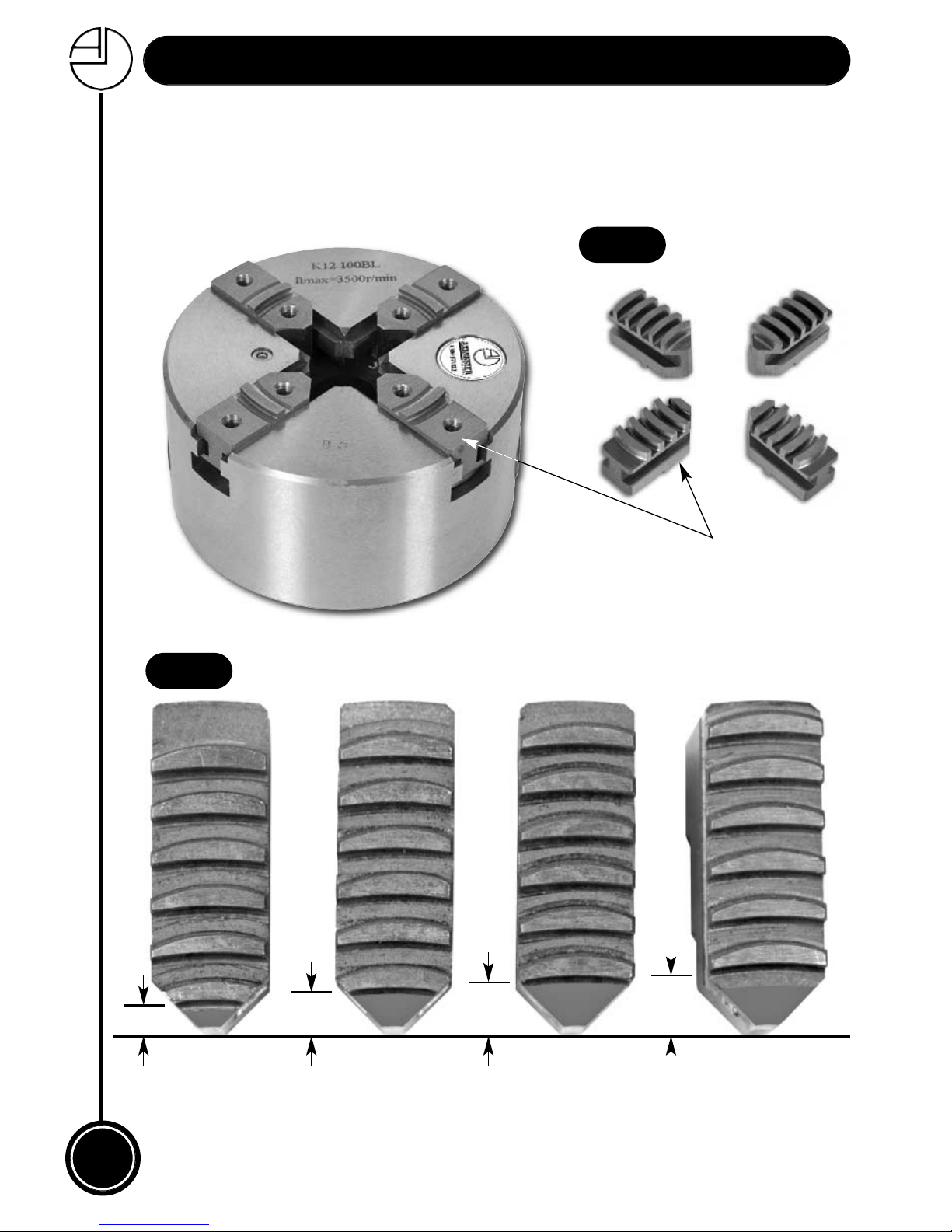
When you receive your chuck it will be fitted with the accessory mounting jaws. (See fig A).
To refit or change to other jaws proceed as follows. Using the chuck key provided, insert it
into the pinion and wind in an anticlockwise direction until all four jaws are free and can be
slid from the chuck body; when you remove these, note that the chuck jaw lugs have
different lead distances from the nose to the first face of the lugs. (See fig B)
Mounting Jaw
A
B
C
D
Jaw A = Smallest Jaw D= Largest
A=1 B=2 C=3 D=4
Showing the Different Lead Distances of the Jaw Lugs
Fig B
Fig A
Page 9
09
Changing the Chuck Jaws...
FREEPHONE 0800 371822
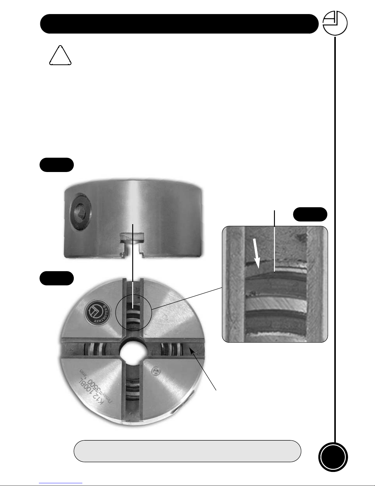
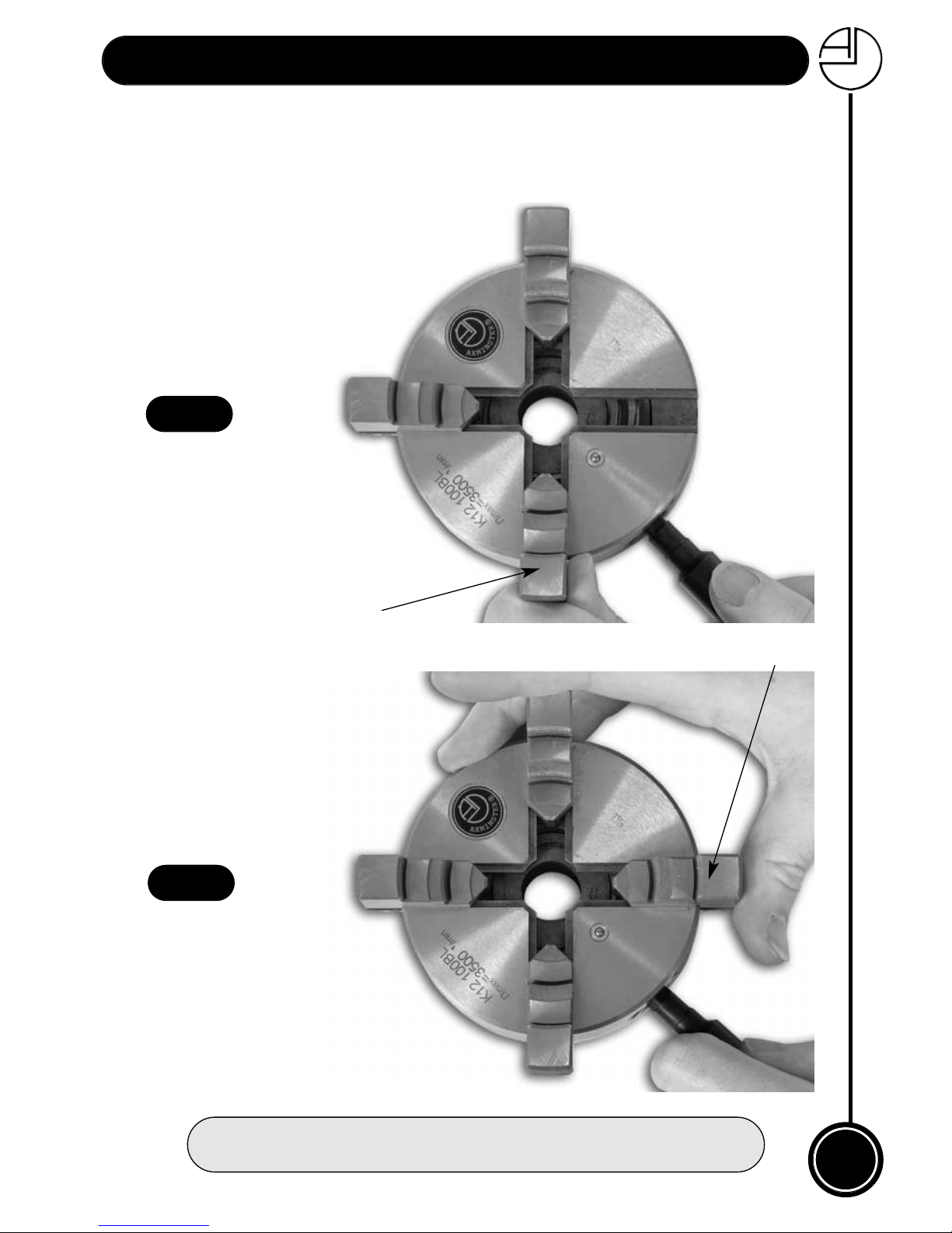
Select the jaw (1) then rotate the chuck key clockwise until the outer end of the scroll is half
way across the first recess (See figs 1,1a & 1b), then turn back until it’s about to enter the
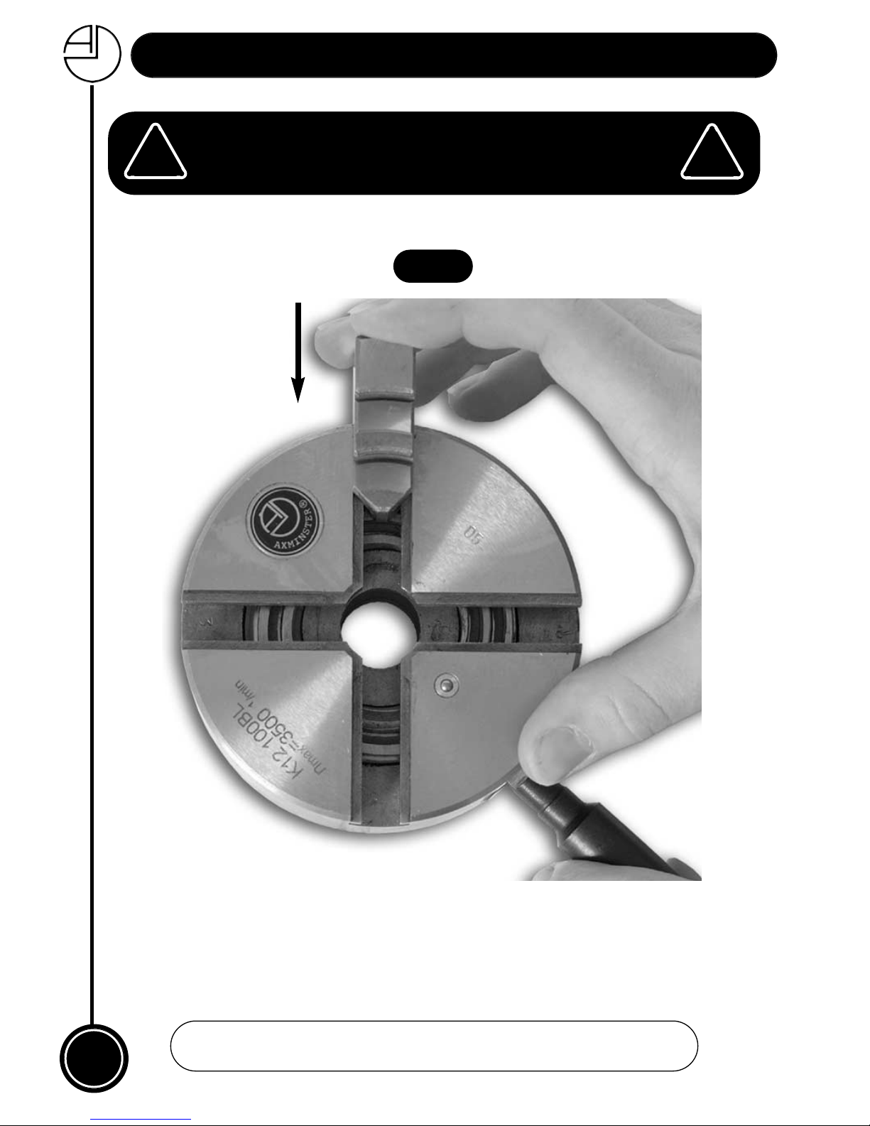
recess. Insert jaw (1) and apply inward finger pressure to the jaw at the same time as
turning the scroll forward again (See fig 2)(confirm the jaw has engaged in the scroll),
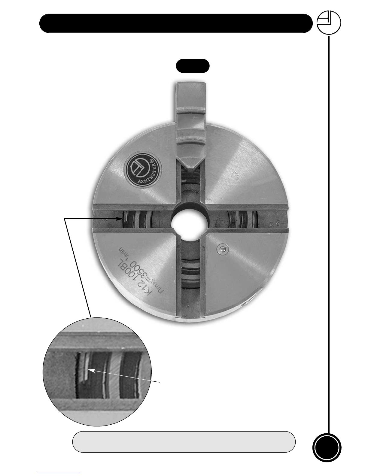
continue to rotate the chuck key clockwise until the outer end of the scroll enters the
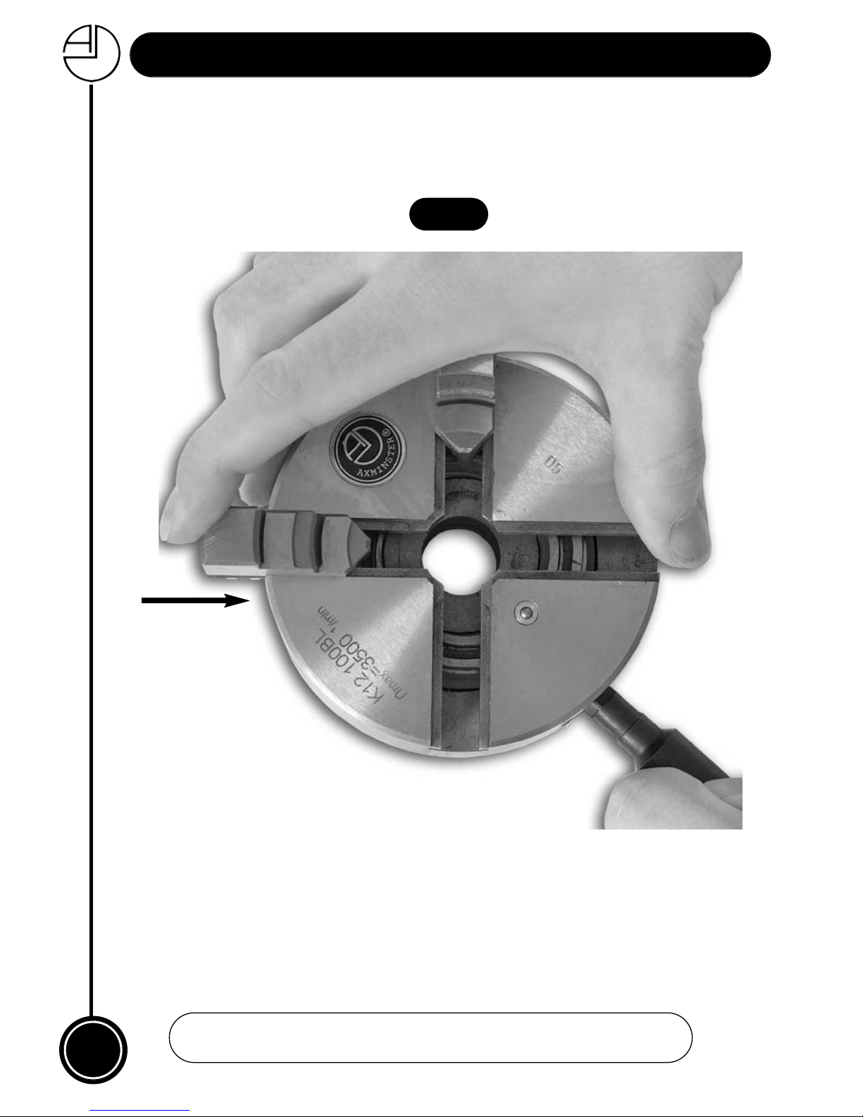
second recess. Turn back the scroll as before and insert Jaw (2),apply finger pressure
while turning the chuck key to move the scroll to the next recess (See figs 3 & 4) (confirm
the jaw has engaged in the scroll), repeat until all the jaws are in place then close the jaws
completely to confirm correct fitting. (See fig 7).
NOTE: YOU CAN SELECT ANY OF THE FOUR RECESSES IN THE
CHUCK TO INSERT THE FIRST JAW, MAKING SURE THAT YOU
FIT THE REST IN SEQUENCE IN AN ANTICLOCKWISE
DIRECTION.
Fig 1
Fig 1b
Scroll
Fig 1a
!
Recess
Page 10
10
Changing the Chuck Jaws...
Fig 2
Insert jaw (1) apply inward finger pressure to the jaw while turning the
chuck key, check the jaw is engaged in the scroll.
Jaw (1)
Always install the jaws in an
anticlockwise direction
!
!
www.axminster.co.uk
Page 11
11
Changing the Chuck Jaws...
FREEPHONE 0800 371822
Fig 3
Scroll
Rotate the chuck key clockwise
until the outer end of the scroll
enters the second recess.
Page 12
12
Changing the Chuck Jaws...
www.axminster.co.uk
Fig 4
Turn back the scroll until its about to enter the second recess, then insert
jaw (2) apply inward finger pressure, continue turning the chuck key until it
reaches the third recess, check the jaw is engaged in the scroll.
Jaw (2)
Page 13
13
Changing the Chuck Jaws...
FREEPHONE 0800 371822
Fig 5
Turn back the scroll as before then insert jaw (3) continue turning the chuck key to the
fourth recess and install jaw (4). When all jaws have been installed, turn the chuck key until
the jaws are completely closed to confirm correct fitting. (See fig 7).
Fig 6
Jaw (3)
Jaw (4)
Page 14
14
Changing the Chuck Jaws...
www.axminster.co.uk
Close the jaws completely to
confirm correct fitting.
JAW 1
JAW 2
JAW 4
Accessory Mounting Jaws
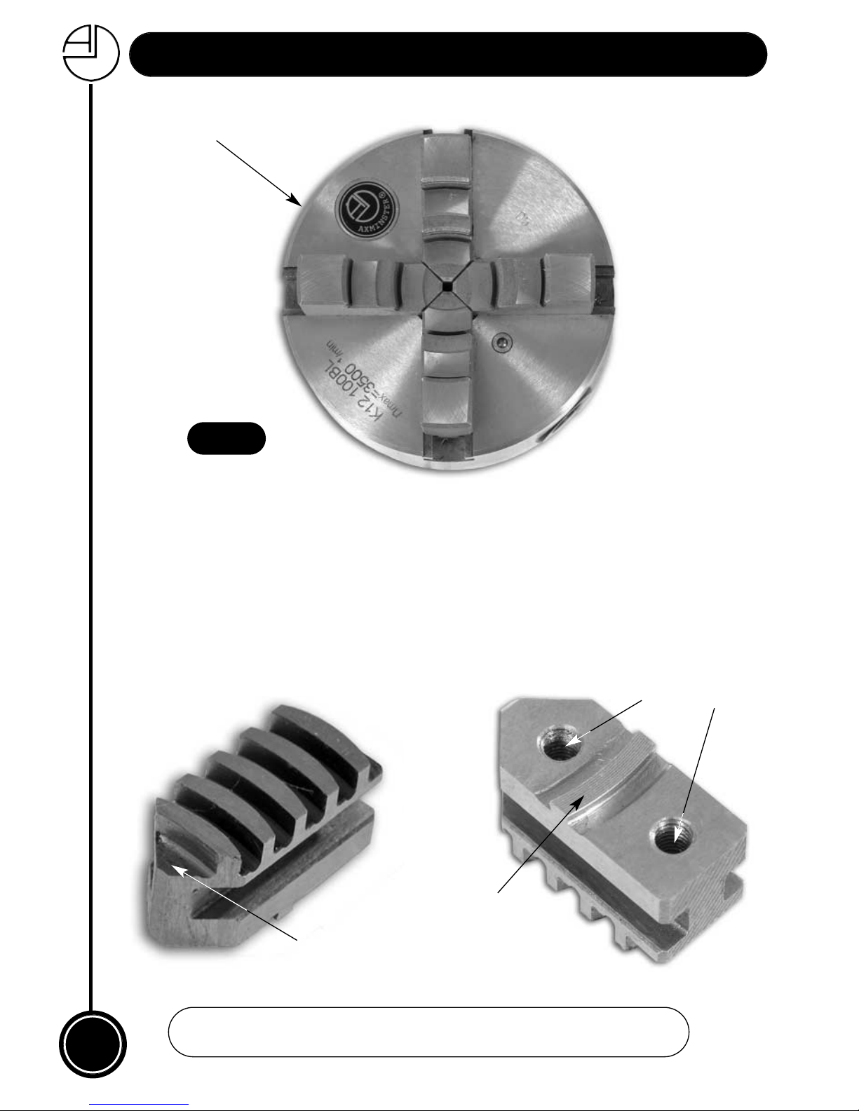
These jaws have different lead distances exactly similar to the engineering jaws and are fitted
in the same way as the internal & external jaws. The accessory mounting jaws carry a register
ring and have two M5 tapped holes on the upper surface to locate & secure the accessory
jaws.
N.B When fitting any additional items to these accessory jaws leave the M5 securing screws
approx; half a turn slack, firmly close the chuck, then finally tighten the screws, this will
ensure correct alignment.
Fig 7
Lead distance
M5 tapped holes
Register ring
JAW 3
Page 15
Woodturning Chuck Jaws...
15
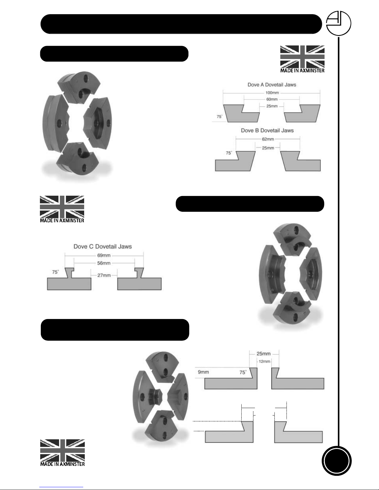
The A dovetail jaws are
designed to expand into a
100mm recess and compress on to both 60mm
and 25mm spigots. The B
dovetail gives expansion
into a 62mm recess and
compression on a 25mm
spigot.
Order no: 410158 Type A Jaws
Order no: 410159 Type B Jaws
TYPE A&B DOVETAIL JAWS
TYPE C DOVETAIL JAWS
The C dovetail jaw expands
into a 69mm recess and has
a specially lipped internal
grip onto a 56mm spigot
especially designed for end
grain work such as boxes
and goblets.
Order no: 410161 Type C Jaws
These jaws for small work
holding are dovetailed for
gripping internally and have
a plain bore for spigot holding. The two sizes of dovetail offered are 25mm and
38mm respectively at their
optimum grip and 12mm
and 19mm for their central
bore.
DOVETAIL JAWS FOR SMALL WORK
(DOVE D & F)
Order no: 410164 Type D Jaw
Order no: 410167 Type F Jaw
75˚
19mm
38mm
9mm
DOVE F Dovetail Jaws
DOVE F Dovetail Jaws
Page 16
16
Woodturning Chuck Jaws...
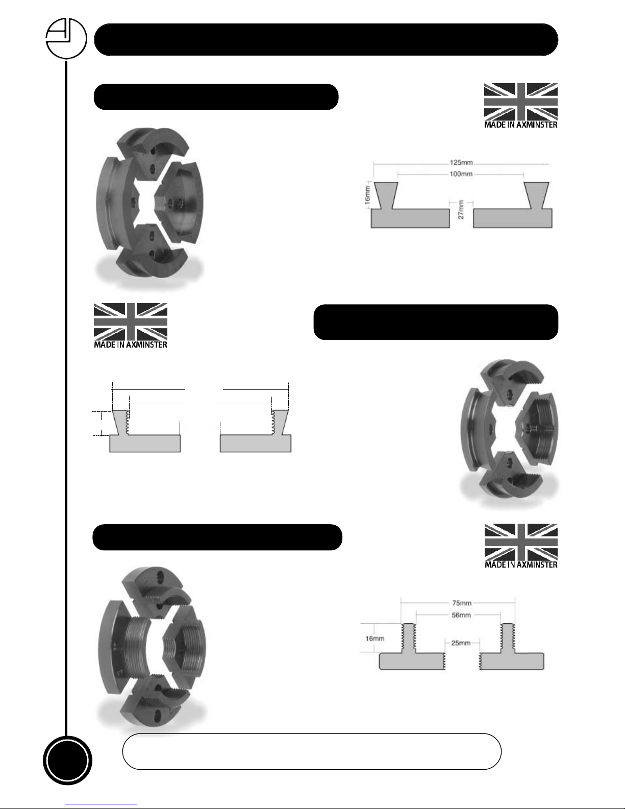
The external diameter is
125mm and the internal
spigot will grip onto a
100mm diameter by 16mm
spigot. These are the jaws
to choose for large platters
etc. and destined to be an
all time favourite.
TYPE M MEGA JAWS
Order no: 410174 Mega Jaws
AXMINSTER LARGE GRIPPER JAWS
(DOVE G)
Specially designed to give a
massive grip, particularly on
large diameter parallel pieces.
The type G gripper jaws have a
large dovetail on the outside for
turning large platters and bowls
and a serrated grip on the inside
specially designed to hold large
hollow forms and end grain
pieces.
25mm
112mm
87mm
16mm
75˚
Order no: 410168 Type G Jaw
TYPE H MEDIUM GRIPPER JAWS
Similar to the Type G, these
jaws provide excellent work
holding especially for large
diameter pieces. The main
gripping surfaces are
serrated on the internal and
external walls and also on
the central spigot grip.
Order no: 410170 Type H Jaw
www.axminster.co.uk
Page 17
For those of you who wish to turn very large hollow forms and
big bowls and platters, we have introduced the Colossus
Gripper Jaws. Based on the well established design of our very
popular G type gripper jaws but offering a greatly increased
work holding capacity for very large projects. The jaws will
expand into a 150mm(6”) dovetailed recess or grip onto a
spigot of approximately 125mm(5”) in diameter. Perfect for
those large
unseasoned
logs you may
want to turn
into an objet
d’art.
17
Woodturning Chuck Jaws...
TYPE BF SMALL GRIPPER JAWS
Order no: 410160 Type BF Small Gripper Set
A development of the very
successful type H three position gripper jaw, the BF offers
the same power but for
smaller diameters. Optimum
sizes are 36mm externally
and 20mm internally with the
internal serrated grip extending for 30mm, giving unrivalled gripping power on
spigots.
AXMINSTER COLOSSUS 150mm GRIPPER JAWS
Order no: 210887 Colossus Gripper Jaws 6"
The Havita jaws have a standard dovetail on the expansion side of the jaw with an
optimum diameter of 72mm
and a radiused grip on the
inside. This enables the
turner to produce a finished
decorative spigot with a
6mm cove and hold this
accurately and firmly without damage to the finished
piece.
Order no: 410175 Havita Jaws
Order no: 410173 Havita Plus Jaws
HAVITA DOVETAIL JAW
Page 18
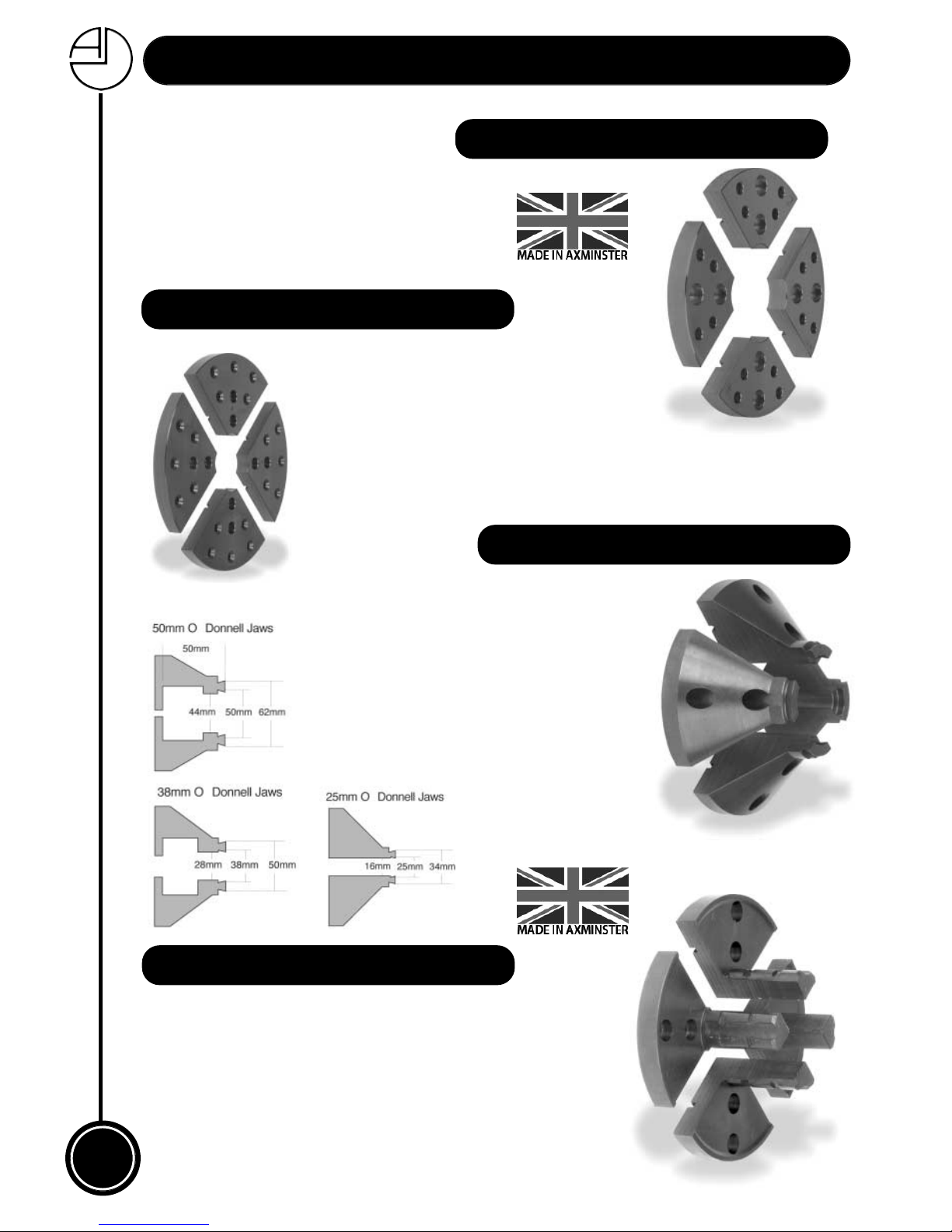
Order no: 810067 Spigot Jaws
These second generation spigot jaws have been designed to give
an improved grip when working with green wood. Similar in
operation to a pin chuck, the spigot jaws are inserted into a 30mm
diameter by 50mm deep hole in the blank and the jaws expanded
into the hole. It is important to use the full depth of the jaws in order
to give the best possible grip and to avoid over-stressing and
damaging the jaws. Should the grip loosen during turning then
another tweak on the key will soon restore it.
18
Woodturning Chuck Jaws...
150mm WOOD JAW PLATES
A larger version of the wood jaw plates
giving scope for turning larger bowls.
The greater diameter of the plates gives
scope for larger wooden jaws which are
less prone to distort under the
tightening loads.
Order no: 910405 Wood Plate 150mm
100mm WOOD JAW PLATES
A set of pre-drilled steel quadrants onto which
self-made wooden jaws can be mounted using
woodscrews. The wooden jaws can be used
for rechucking a bowl when removing a
dovetailed recess or spigot, or for producing a
variety of ‘jam’ chuck-type holding devices.
Order no: 910403 Wood Plate 100m m
Designed to give access around the
jaws for close-in tool work. With a deep
recess for holding long spigots and
giving rock solid mounting when turning
a long way from the headstock without
tailstock support. The jaws are also
dovetailed both inside and outside on
the lip. Three sizes are produced - the
size stated is the nominal bore of the
spigot recess.
AXMINSTER O'DONNELL SPIGOT JAWS
Order no: 610356 25mm
Order no: 610357 38mm
Order no: 211354 50mm
AXMINSTER Spigot Jaws
Page 19
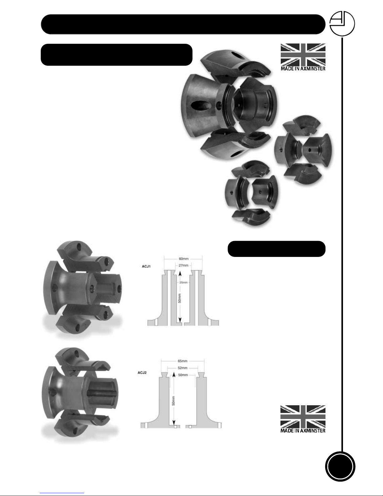
This is a great idea, a set of three O’Donnell
jaws, spigotted together and secured with
four screws, giving a range of three sizes,
25mm, 38mm or 50mm, by simply undoing the
screws and sliding the inserts in or out. Our
sincere thanks to the customer who suggested
this idea. Supplied as a complete set of three
jaw sizes with four allen cap head screws and a
hex wrench. The jaws and inserts are now available separately so you might want to start with the
50mm jaws(211354) and add the inserts at a later date,
but there is a price advantage if you buy them all together.
19
Woodturning Chuck Jaws...
Order no: 718321 O’Donnell Jaw Set
Order no: 211328 25mm O’Donnell Jaw inserts
Order no: 211327 38mm O’Donnell Jaw inserts
Order no: 211354 50mm O’Donnell Jaws
When turning long and thin
projects it’s a great advantage to
be able to grip a blank along a
substantial amount of its length to
impart a good measure of stability
to the workpiece. To overcome this
problem we have designed a pair
of cylindrical jaws, one with a
25mm diameter by 50mm long
bore and the other with a 50mm
diameter by 50mm long bore to
accommodate a range of
workpiece sizes. In addition,
because we are always loath to
provide you with jaws which
perform only one function, we
have added internal and external
vetails on the ends.
310425
310424
CYLINDER JAWS
Order no: 310424 Cylinder Jaws 25mm
Order no: 310425 Cylinder Jaws 50mm
AXMINSTER O’DONNELL JAW SET
(Set of Three 25mm, 38mm,50mm)
Page 20
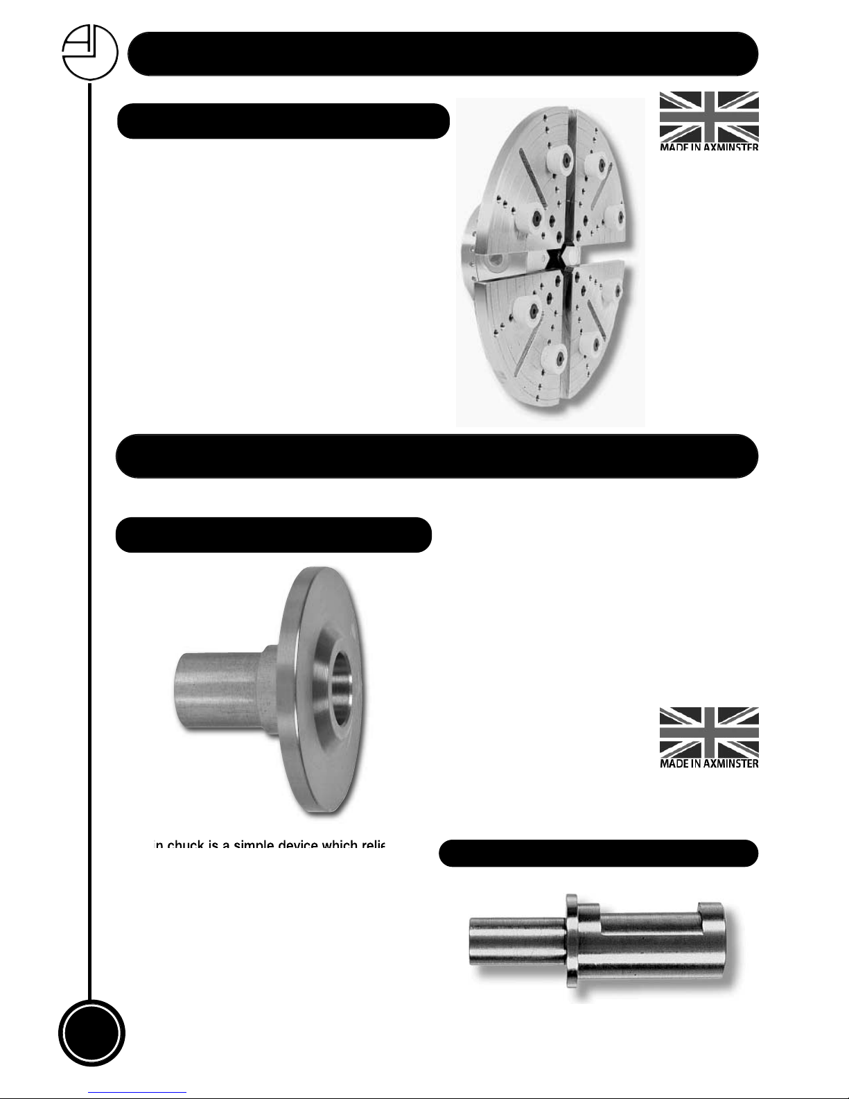
The pin chuck is a simple device which relies on
the cam action of a pin rolling on a flat machined
on the shaft to provide a secure grip for the
workpiece. All that is required is a 25mm hole
bored in the end of the timber; this is then slid onto
the pin chuck with the pin in position on the flat and
when the timber is rotated slightly the pin jams
between the flat and the timber and locks it firmly in
position on the chuck. The 5/8” diameter mounting
shaft will fit in the nose of the accessory mounting
jaws of the Super Precision, Woodturner’s or
Clubman K10 chucks.
20
Woodturning Chuck Jaws...
Order no: 400019 1MT Carrier for C Jaws
Order no: 400020 2MT Carrier for C Jaws
Order no: 800340 Pin Chuck 25mm
AXMINSTER MORSE TAPER CARRIERS
Available in either 1 or 2 Morse taper, these carriers
fit into the C chuck jaws and enable drive centres
or arbors to be mounted without the need to
remove the chuck from the lathe. You could, of
course, purchase a carrier with a different taper
from that of your lathe, thereby extending the
range of usable centres.
AXMINSTER PIN CHUCK
Chuck Accessories...
These jaws use eight conical rubber buttons to
securely pull back work onto the jaws. They are
intended for use with bowls up to 9" in diameter.
However, they may not be suitable for bowls
with very thin edges as the pressure may
deform the bowl edges.
The buttons are white rubber so as not to mark
the workpiece and are "dovetailed" to hold the
workpiece firmly against the plates.
AXMINSTER BUTTON JAWS
Order no: 340956 Jaws 250mm
Order no: 340957 Jaws 400mm
Page 21
21
Chuck Accessories...
FREEPHONE 0800 371822
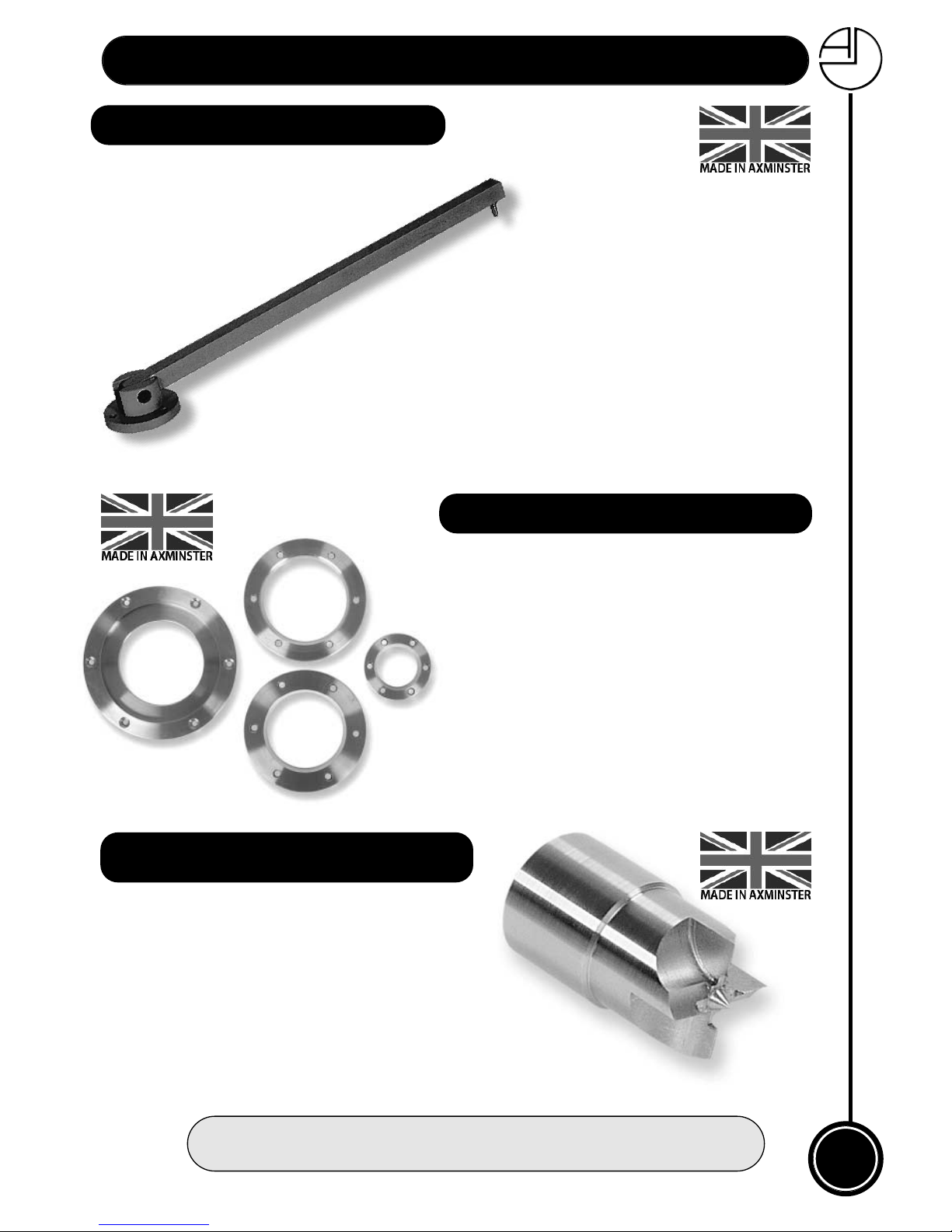
Made to match the dovetail jaws, these rings do away with
the need for a separate faceplate on which to mount a bowl
blank prior to turning the outside. Simply screw the ring to
the chosen blank with woodscrews and expand the dovetail
jaws into the recess in the centre of the ring.
The Axminster four prong parallel drive centre has been
designed to be used in the central bore of the C jaws
fitted to the Carlton, Super Precision, Woodturner’s and
Clubman chucks. It has principally been produced for
those lathes that do not have a hollow headstock, but can
also be used for those combined jobs where spindle
turning is necessary before mounting the workpiece in the
chuck.
Order no: 410052 Parallel Drive Centre (to suit DOVEC jaws)
Order no: 500166 Faceplate Ring A Jaws
Order no: 500167 Faceplate Ring B Jaws
Order no: 500168 Faceplate Ring C Jaws
Order no: 500170 Faceplate Ring F Jaws
AXMINSTER FACEPLATE RINGS
AXMINSTER
FOUR PRONG PARALLEL DRIVE CENTRE
Order no: 510217 Indexing Arm
AXMINSTER INDEXING ARM
A universal, indexing arm for use
with Axminster chucks, either the
Super Precision with its
indexing holes around
the backplate or the Woodturner’s
chuck with the addition of the indexing
ring (Order No. 510256). The base is
secured to any convenient fixed object,
preferably the lathe itself, so that the pin will drop
conveniently and tangentially into the register holes
on the rim of the chuck. The Axminster Indexing
Arm is made from aluminium and anodised for
protection, with a precision machined steel pin.
Page 22
22
Chuck Accessories...
Maintenance...
As mentioned on page seven, the four jaw chuck requires very little maintenance. In the
event of the chuck requiring attention it will generally only be due to a build-up of dust it
may be dismantled for cleaning with the aid of just a screwdriver. After cleaning, the chuck
should be re-assembled adding a little dry lubricant or a smear of light machine oil. One
component that may present difficulty is the refitting of the scroll ring, this item is a very
precise fit and must be dropped on squarely. Do not attempt to drive the part on with a
hammer or hard punch, but strike the front face of the chuck with a soft mallet or drop the
chuck face down on to a firm surface.
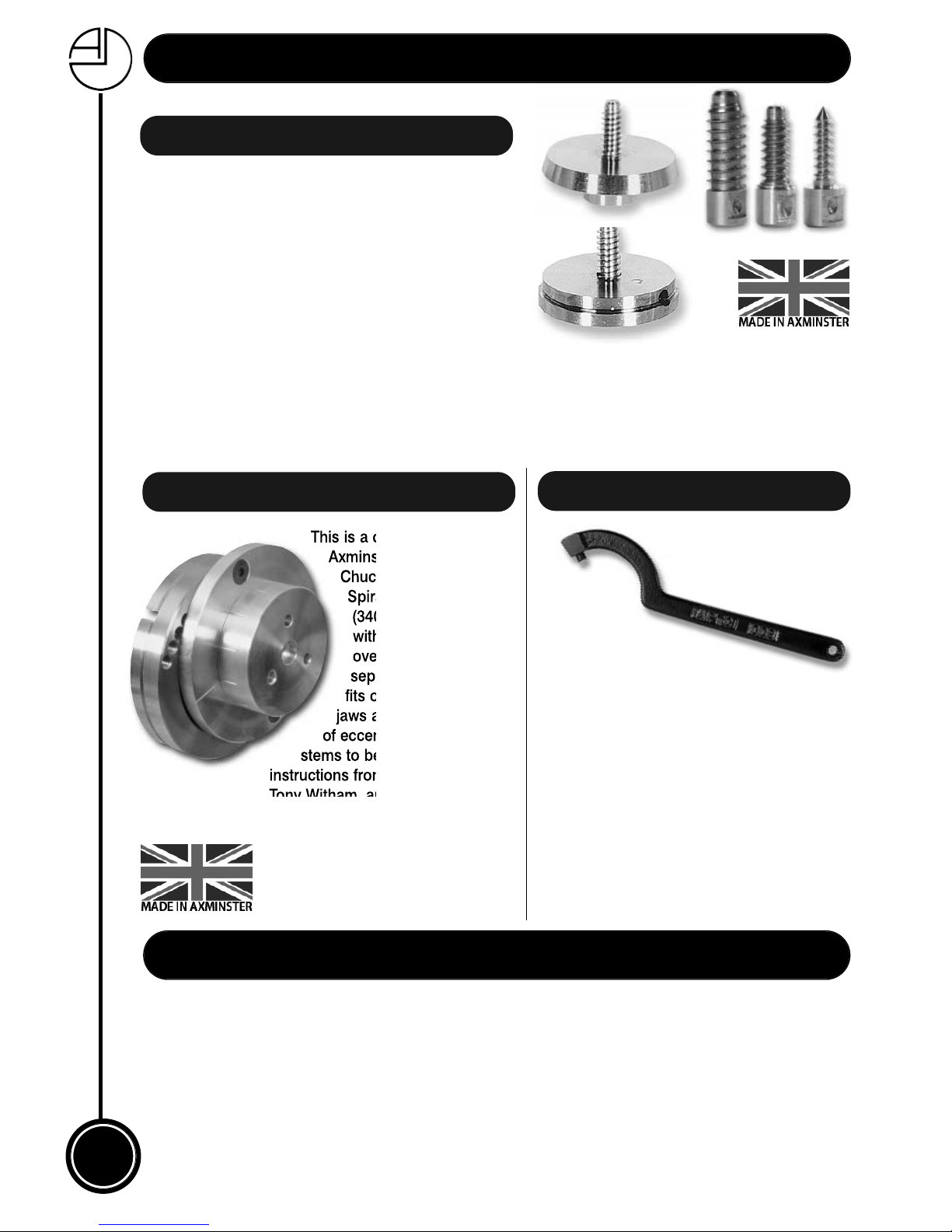
A replaceable stainless steel parallel screw
mounted onto a boss which fits into either the 62mm
recess of the A dovetails or the internal recess of the
C dovetail jaws. Particularly useful for the initial
mounting of bowl blanks whilst the outer form and
the dovetail base are being shaped. Once this stage
is completed the woodscrew chuck can be removed
and the bowl mounted directly into the chuck jaws in
a matter of seconds. Replacement screws, which are
interchangeable, are available for all Axminster screw
chucks and are listed below.
Order no: 810383 (To Fit A Dovetail)
Order no: 810385 (To Fit C Dovetail)
Order no: 910458 Small Screw
Order no: 210886 Medium Screw
Order no: 910466 Large Screw
AXMINSTER SCREW CHUCKS
AXMINSTER ECCENTRIC SPIRAL CHUCK
CHUCK REMOVAL SPANNER
This is a combination of the
Axminster Eccentric
Chuck (340152) and the
Spiralling Attachment
(340155) sold together
with a price reduction
over the two items sold
separately. The chuck
fits onto the C dovetail
jaws and allows a variety
of eccentric and spiralled
stems to be produced. Full
instructions from the designer,
Tony Witham, are included.
Order no: 900093
One
important
lesson for woodturners
to learn is not to use the chuck
key for removing the chuck from the
headstock; doing this can damage the hole
in the chuck as well as risking breaking the
key. This C spanner has been specially
produced for the 100mm Clubman, Goliath
and previous model Woodturner’s range of
chucks. This should be classed as essential
equipment for all users of these chucks.
Order no: 340220
Page 23
23
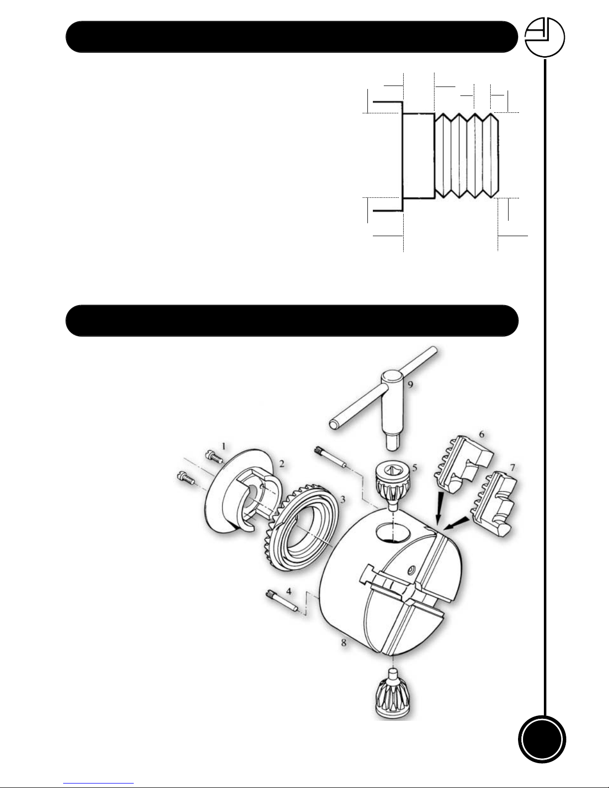
Lathe Thread Information....
Item 4”
No: Part No.
1 A891141 Keeping Screws
2 A891142 Lock Plate
3 A891143 Scroll
4 A891144 Pinion Screw
5 A891145 Pinion
6 SJEXT External Jaws (Set of 4)
7 SJINT Internal Jaws (Set of 4)
8 A891148 Body
9 A891149 Chuck Key (Std)
9A LCK Long Chuck Key
Lathe Thread Information
This table lists all the stock thread types which can be used when
ordering any of the threaded items, such as chucks, chuck
backplates, faceplates and screw chucks, from the catalogue.
If you are uncertain about which thread to specify please ring
our Technical Department who will be pleased to help. They
will need to know either the make of the lathe or the
dimensions of the lathe spindle as shown in the diagram. The
column heading numbers refer to the dimensions in the
diagram as follows:
1. Register diameter.
2. Register length.
3. Thread diameter.
4. Combined length of thread and register.
5. Thread pitch, either threads per inch or thread pitch if metric.
2
4
1
3
5
Parts Breakdown....
Page 24
100247
www.axminster.co.uk
Axminster Devon EX13 5PH UK
FREEPHONE 0800 371822
Axminster Super Precision Woodturning Chuck
Thread Code Thread Size Lathe Type 1 2 3 4 Tpi/Pitch
T01 3/4" x 16tpi Carbatec, Coronet, Record 3/4" 3/16" 3/4" 11/16" 16
T02 1 1/2" x 6tpi NV28-40, Supalathe, Graduate 1 1/2" 3/8" 1 1/2" 1 1/8" 6
T03 1" x 12tpi Myford ML8, Turnstyler 1 1/8" 3/8" 1" 1" 12
T04M 1" x 8tpi APTC M Series Lathes, Delta 1" 1/4" 1" 1 1/8" 8
T06 1 1/2" x 8tpi Powermatic 1 1/2" 3/8" 1 1/2" 1" 8
T23 1 1/4" x 8tpi General 260 1 1/4" 1/8" 1 1/4" 1" 8
T37 30mm x 3.5mm Minimax 30mm 18mm 30mm 40mm 3.5mm
T38 33mm x 3.5mm
Hegner, Kity, Konig, Jet 3520B,1642, 1442
34mm 16mm 33mm 30mm 3.5mm
T38W 33mm x 3.5mm Woodfast, 33mm 6mm 33mm 29mm 3.5mm
T38PRO * 33mm x 3.5mm 4224 Professional, 3520A 33mm 4mm 33mm 37mm 3.5mm
T38V Special Fitting Vicmarc
VB36 Special Fitting VB36
Thread Code Thread Size Lathe Type 1 2 3 4 Tpi/Pitch
T02RL 1 1/2" x 6tpi Harrison Graduate and
APTC Woodfast Lathes to suit 1 1/2" 3/8" 1 1/2" 1 1/8" 6
both sides of the headstock
Right Hand/Left Hand Threads
Right Hand Threads
Please measure register diameter (1) to ensure the correct fitting
 Loading...