

Page 1
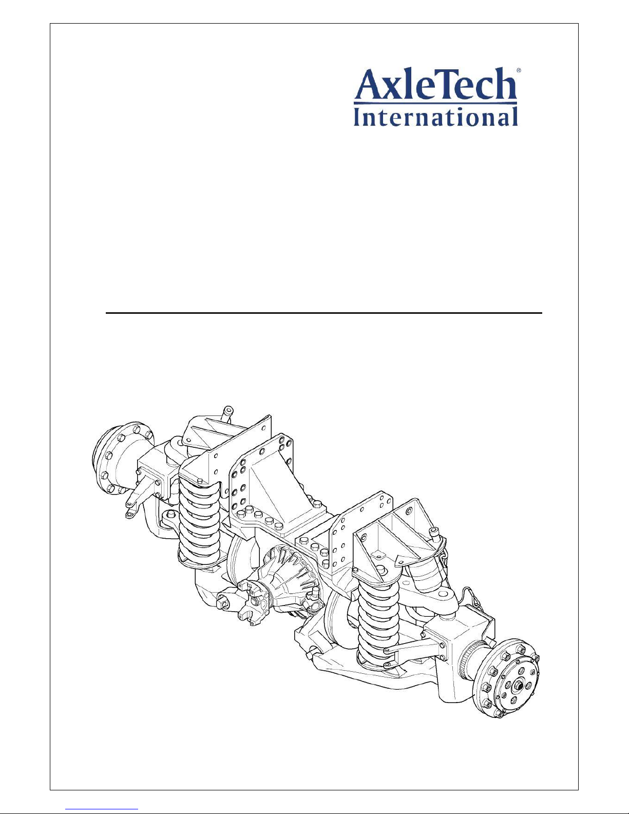
Independent Suspension
Axle System
5000 Series
Maintenance Manual ISAS5
Issued -201
ISAS5 SEPTEMBER, 2017
Page 2
i
WARNING
A Warning alerts you to
an instruction or
procedure that you must
follow exactly to avoid
serious personal injury
and damage to
components.
CAUTION
A Caution alerts you to
an instruction or
procedure that you must
follow exactly to avoid
damage to components
and possible serious
personal injury can also
occur.
The torque symbol alerts
you to tighten fasteners
to a specified torque
value.
NOTE:
A Note provides
information or
suggestions that help you
correctly service a
component.
ISAS5 SEPTEMBER, 2017
Service Notes
Before You Begin
This manual provides maintenance and service
pr o ce d ure s f o r Ax leT e ch ’ s i n dep end en t
suspension axle system ISAS 5000 Series. The
information contained in this manual was current
at the time of printing and is subject to change
without notice or liability. Before you begin
procedures:
1. Read and understand all instructions and procedures before you begin to service components.
2. Read and observe all Caution and Warning
safety alerts that precede instructions or procedures you will perform. These alerts help to
avoid damage to components, serious personal injury, or both.
3. Follow your company’s maintenance and service, installation, and diagnostics guidelines.
4. Use special tools when required to help avoid
serious personal injury and damage to components.
Safety Alerts, Torque Symbol and
Notes
Page 3

i
ISAS5 SEPTEMBER, 2017
Table of Contents
Section 1 - Exploded Views
Differential .............................................................................................. 1-1
Suspension ..................................................................................... 1-2
Hub Reduction ................................................................................ 1-3
Section 2 - Disassembly
Removal of Springs and Shock Absorber ............................................. 2-1
Cardan Joint ............................................................................................... 2-2
Suspension ................................................................................................. 2-2
Brake Disc ................................................................................................... 2-3
Differential Halfshaft ....................................................................................... 2-4
Hub Reduction ............................................................................................ 2-5
Section 3 - Inspection
Tapered Roller Bearings ................................................................................... 3-1
Seals .................................................................................................................. 3-1
Replacing a Wheel Stud .................................................................................... 3-1
Fasteners ..................................................................................................... 3-1
Section 4 - Assembly
Hub Reduction ............................................................................................ 4-1
Differential Halfshaft ....................................................................................... 4-6
Brake Disc ................................................................................................... 4-7
Suspension ................................................................................................. 4-7
Cardan Joint ............................................................................................. 4-11
Shock Absorber ....................................................................................... 4-11
Section 5 - Lubrication
Oil Change ................................................................................................... 5-1
Lubrication .................................................................................................. 5-2
Section 6 - Special Tools
Tool drawings ............................................................................................. 6-1
Page 4
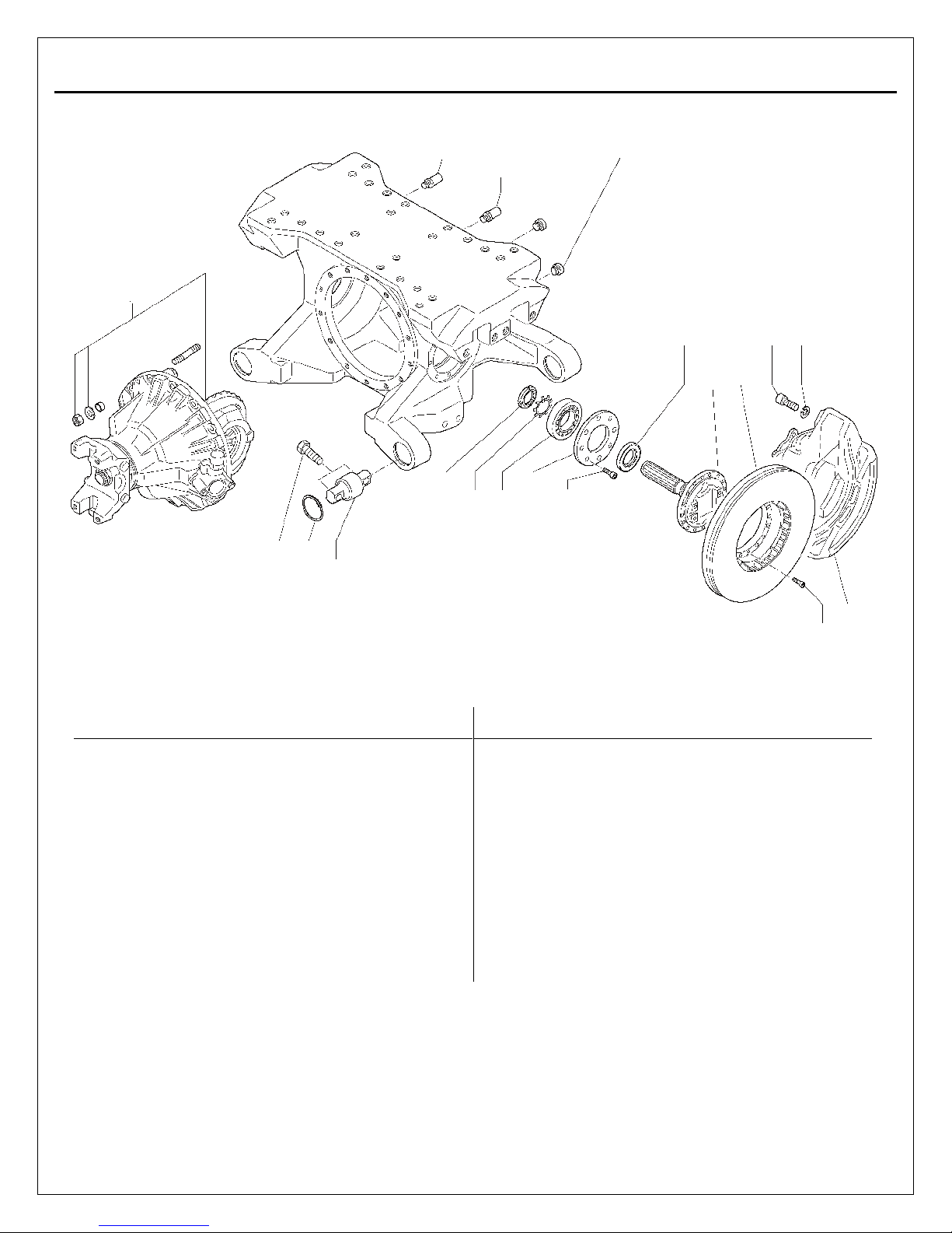
1-1
Item
Qty Description
Item
Qty Description
1 1 Axle housing
11
16
Socket head capscrew - M8x1.25x25 (grade 8.8)
2 1 Carrier assembly
12 2 Halfshaft
3 2 Breather
13 2 Brake disc
4 1 Filler plug
14
32
Socket head capscrew - M8x1.0x35 (grade 10.9)
5 1 Drain plug
15 1 Brake assembly
6 2 Lock nut - M48x1.5
16 8 Lock washer
7 2 Lock washer
17 8 Socket head bolt - M20x1.5x45 (grade 10.9)
8 2 Ball bearing SKF 6410
18 4 Straddle bearing
9 2 Bearing retainer and seal housing
19 4 Circlip internal
10 2 Seal NCR 23479
20 8 Hex head capscrew
1 3 4 5
3
10 12 13 17 16
14 15
6 7 8 9 11
2 0 1 9 1 8
2
ISAS5 SEPTEMBER, 2017
Differential
Page 5
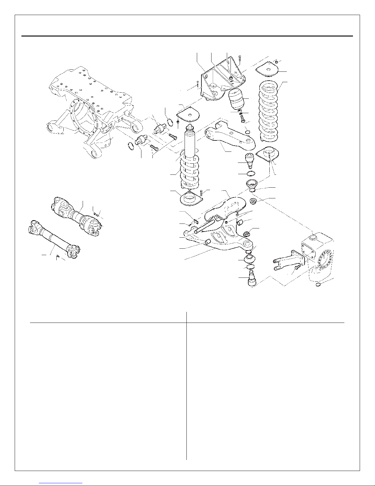
1-2
Item
Qty Description
Item
Qty Description
1 1 Lower wishbone
19 2 Straddle bearing
2 2 Bushing
20 2 Internal circlip
3 1 Lower spring mounting
21 4 Hex head capscrew
4 1 Mounting pivot pin
22 1 Bump stop
5 1 Locking strip
23 1 Washer
6 2 Hex head capscrew - M6x1.0x20 (grade 10.9)
24 1 Hex head capscrew - M12x1.75x70 (grade 8.8)
6a 2 Washer
25 1 Upper spring cap
7 4 Spring locating plate
26 1 Washer
8 4 Hex head capscrew - M10x1.5x40/26 (grade 8.8)
27 1 Nyloc nut - M12x1.75
4
Hex head capscrew - M10x1.5x45/26 (grade 10.9)
28 1 Spacer bushing
9 8 Nyloc nut - M10x1.5
29 1 Steering arm
10 1 Shock absorber
30 4 Hex head capscrew - M20x2x74 (grade 10.9)
11 2 Suspension spring
Steering ISAS
12 2 Core plug
31 1 Double cardan joint
13 2 King pin
32 8 Lock nut - M10x1.5
14 2 Internal circlip
33 8 Stud - M10x1.5x70 (grade 10.9)
15 2 King pin seal
Non-steering ISAS
16
1,4
Lock wire - 4x0.35mm
34 1 Single cardan
17 2 King pin nut
35 8 Socket head capscrew - M12x1.75 (grade 10.9)
18 1 Upper wishbone
25
26
27 8 9 7 11 8 22
1 9 2 0
7
28
23
24
12 9 18
20 19 21 10
11 7 31
32 33
4
8 3
13
14
9
2
17
2
16
29
34
1 15
14
13
35
30
12 5 6
7
8
16
17
ISAS5 SEPTEMBER, 2017
Section 1
Exploded View
Suspension
Page 6
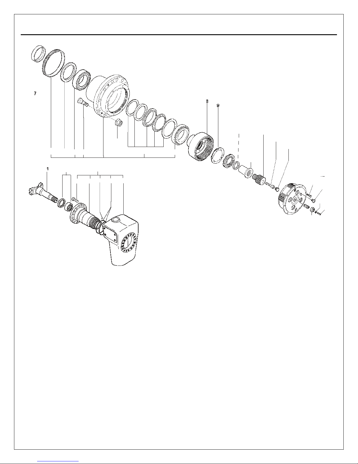
1-3
3
6 3 4 2
30
29
2 6 28
24
1
27
23
25 5 4
10
11
12
13
14
15
19
20
16
18
21
17
22
ISAS5 SEPTEMBER, 2017
Hub Reduction
Page 7
Item Qty Description
Item
Qty Description
1 1 Wheel hub assembly
16 1 Planetary spider assembly
2
10
Wheel stud
17 2 Plug
3 1 Oil seal
18 8 Hex head capscrew - M10x1.5x25/25 (grade 10.9)
4 2 Taper bearing
19 1 Special adjusting screw - M10x1.5 (grade 10.9)
5 1 Central tire inflation sealing kit
20 1 Nut 6 1
ABS ring
21 2 Copper seal
7 1 Seal race
22 2 Socket head capscrew - M6x1.0 (grade 10.9)
8 1 Planetary ring gear hub
23
10
Wheel nut
9 1 Locking washer
24 1 Stub axle assembly
10 1 Spindle nut
25 1 Knuckle
11 1 Spindle ring
26 1 Spindle
12 1 Coupling
27 2 O-ring
13 1 Sun gear
28 2 O-ring
14
1
Socket head capscrew-M14x1.5x90/40 (grade 10.9)
29
16
Socket head capscrew - M16x2.0x40/40 (grade 10.9
)
15 1 Thrust button
30 1 Sealing kit
31 1 Axle shaft
ISAS5 SEPTEMBER, 2017
Page 8
Section 2
Disassembly
2-1
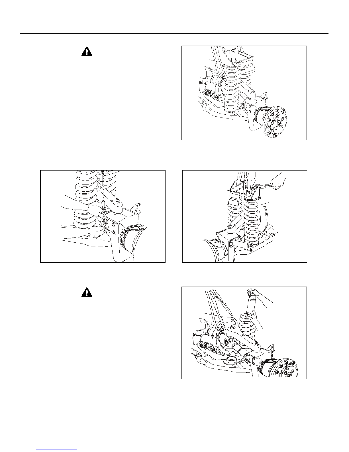
WARNING
Springs must be in the fully extended position
before removal. Failure to do so could result
in serious personal injury.
ISAS5 SEPTEMBER, 2017
WARNING
To prevent serious eye injury, always wear
safe eye protection when you perform vehicle
maintenance or service.
Some models are equipped for shock removal
without requiring the removal of the subframe or
springs. Review your vehicle installation before
proceeding.
Removal of Springs and Shock
Absorber
1. Remove the check strap
NOTE: Not all vehicles are equipped with
check straps. If no check strap, proceed to
step 2.
2. Put the wheel end in the maximum hanging
position.
3. Remove the shock a bsorber upper nut.
Remove the upper spring cap assembly.
Remove the shock absorber lower nut.
4. Remove the sh o ck absor ber an d the 2
springs.
,
Page 9
Section 2
Disassembly
2-2
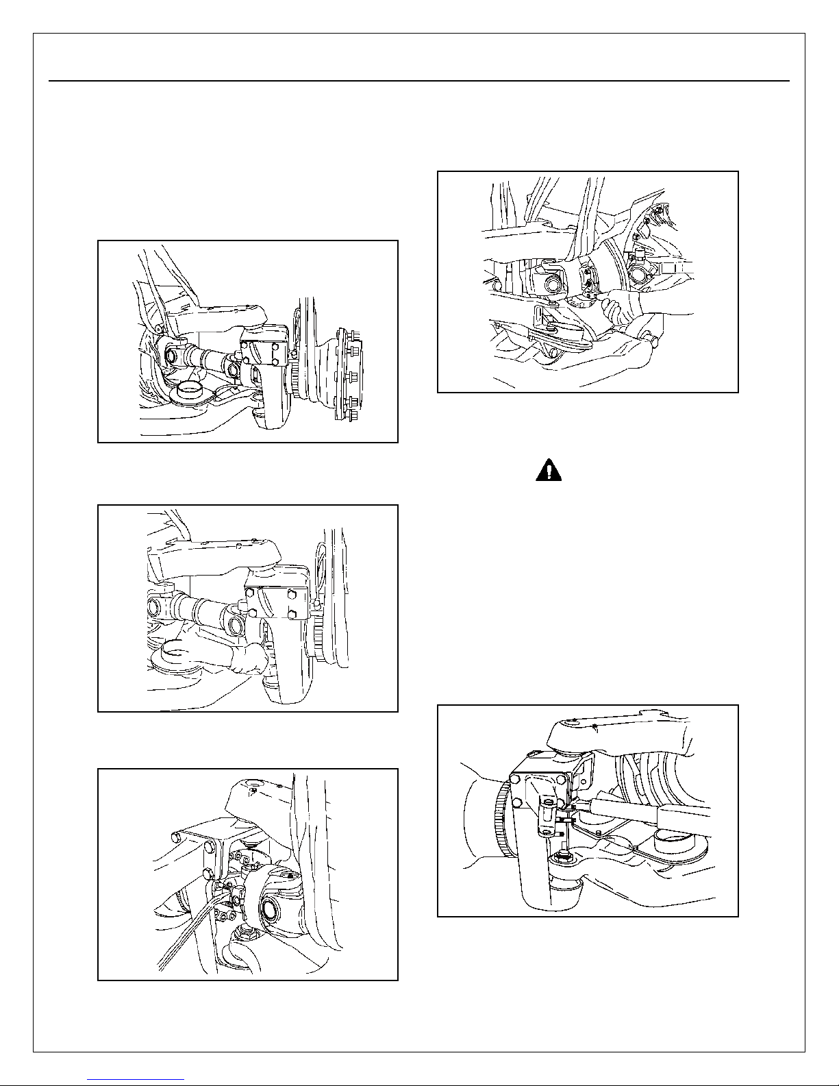
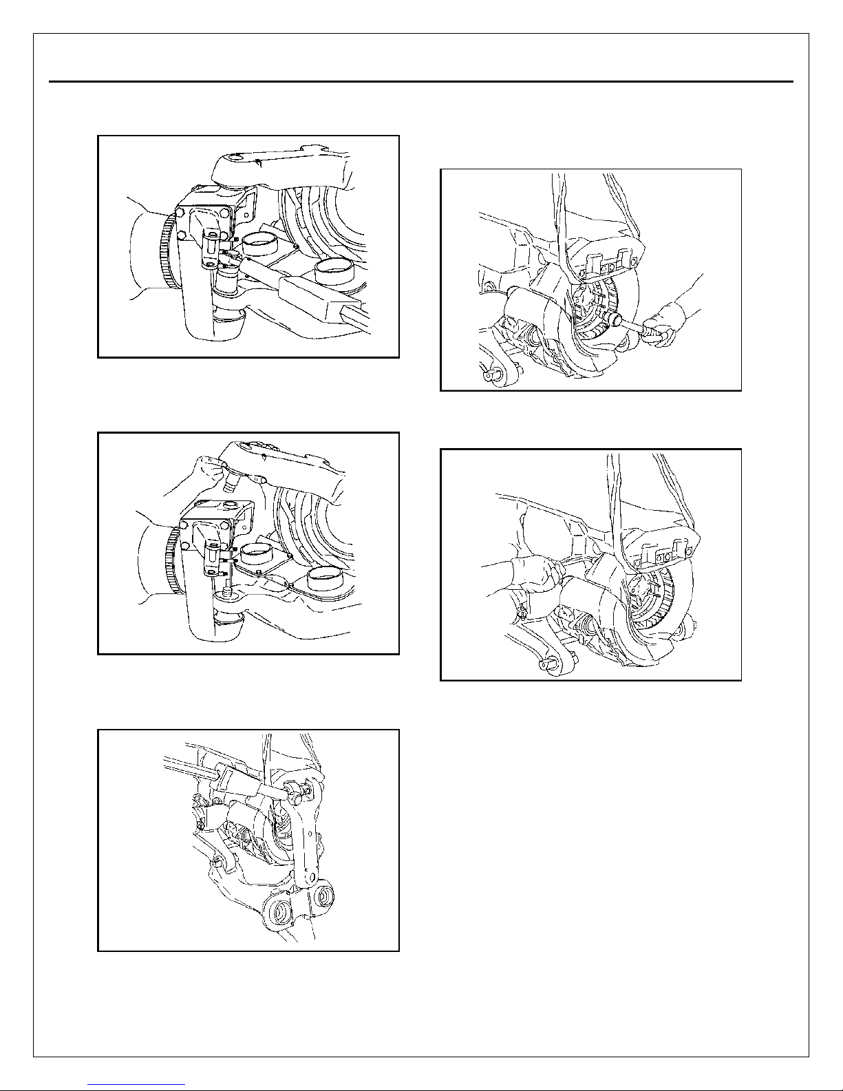
2. Remove the fasteners from the cardan joint,
on the wheel end side.
WARNING
To avoid serious personal injury and damage
to components, be very careful when using
lifting devices for service and maintenance
procedures.
Inspect to make sure that neither lifting
strap is damaged.
Do not subject lifting straps to any
shock or drop loading.
NOTE: Refer to the Suspension exploded view
in Section 1.
1. Remove the upper king pin nut.
ISAS5 SEPTEMBER, 2017
Cardan Joint
NOTE: Steering ISAS uses double cardan
joints with stud and nut fasteners.
Non-steerng ISAS uses single cardan joints
with capscrew fasteners.
1. Align the wheel end with the axle.
4. Remove the fasteners from the universal
joint, on the axle housing side. Separate the
cardan joint, using a lever. Remove the
cardan joint.
Suspension
3. Separate the end of the cardan joint using a
pry bar.
Page 10
Section 2
Disassembly
2-3
2. Remove the lower king pin nut.
3. Using a lifting strap, separate the upper
wishbone. Separate the wheel end from the
lower wishbone. Remove the wheel end.
1. Remove the 16 brake disc bolts.
NOTE: The AxleTech 5000 ISAS uses Meritor
DX225 and DX195 Brakes. For maintenance
information on the brakes, refer to Manual
DX/1/E.
To order this publication, call ArvinMeritor’s
Customer Service Center at 800-535-5560.
ISAS5 SEPTEMBER, 2017
2. Remove the 4 brake caliper bolts. Withdraw
the brake caliper and the disc.
4. Remove the fastening bolts from straddle
bearing. Remove the upper and lower
wishbones.
Page 11
Section 2
Disassembly
2-4
ISAS5 SEPTEMBER, 2017
Differential Halfshaft
NOTE: Refer to the Differential exploded view
in Section 1.
Remove the plug from the bottom of the axle
housing. Drain the lubricant from the assembly.
NOTE: Before removing the axle shaft the
differential lock must be positively engaged.
Remove the differential lock cylinder.
See process in Field Maintenance
Manual MM1 or MM2.
Engage the dog clutch while pulling the
fork and turning a wheel.
Hold the fork with a wire to keep the dog
clutch engaged.
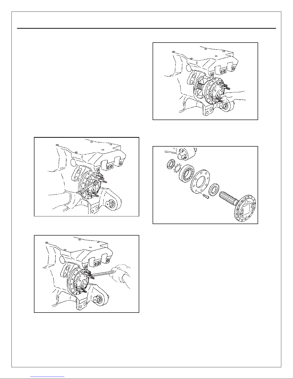
1. Remove the 8 differential shaft bolts.
3. Remove the differential shaft.
4. Unlock and remove the shaft nut. Remove the
lock washer, the ball bearing and the seal
housing. Extract the oil seal from the seal
housing.
2. Use a pry bar to separate the differential
shaft.
NOTE: For maintenance information on the
differential see specific manuals:
Final drive axle: MM1.
Thru drive axle: MM2.
Page 12
Section 2
2-5
ISAS5 SEPTEMBER, 2017
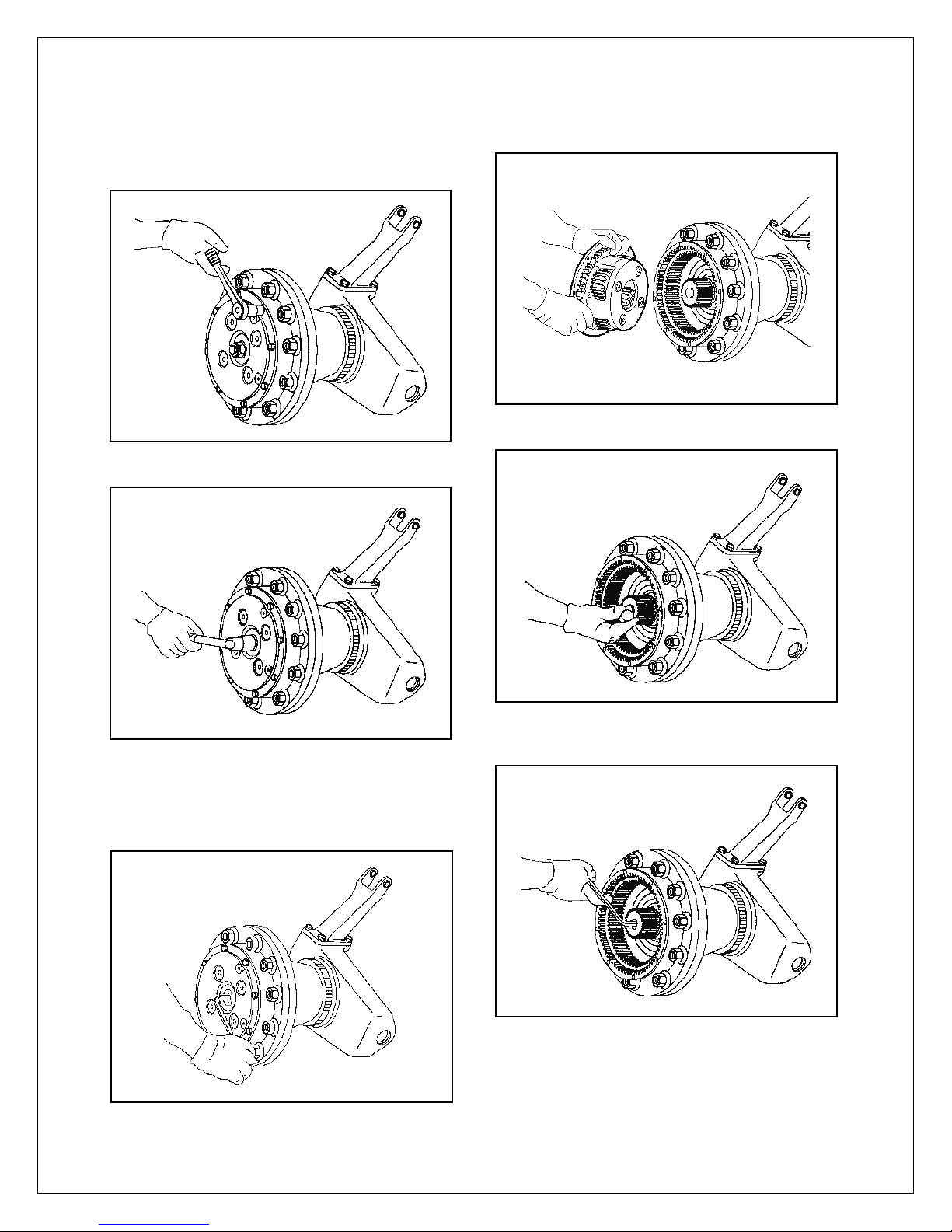
1. Remove the bolts that secure the cover.
2. Unlock and remove nut of adjusting screw.
Disassembly
5. Remove the end thrust button.
7. Unlock the sun gear bolt. Maintain the sun
gear with jet extractor of bronze.
Page 13
Section 2
Disassembly
2-6
WARNING
Gear teeth can be sharp. Wear protective
gloves to avoid serious personal injury.
12. Wearing protective gloves, remove the ring
gear carrier.
ISAS5 SEPTEMBER, 2017
7. Remove the sun gear and the coupling.
8. Rem ove the ax l e s h a f t.
10. Use spanner # 5231 to remove the spindle
nut.
11. Remove spindle nut and lock washer.
9. Unlock spindle nut.
Page 14
Section 2
Disassembly
2-7
ISAS5 SEPTEMBER, 2017
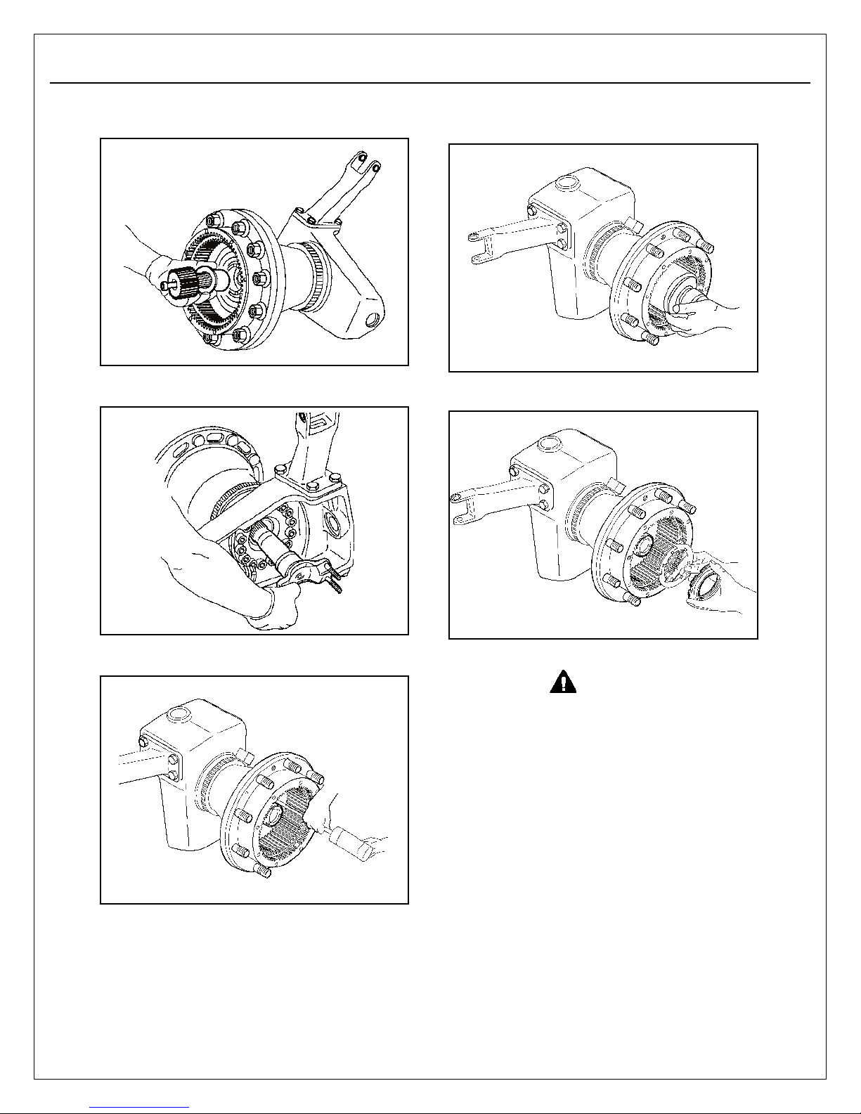
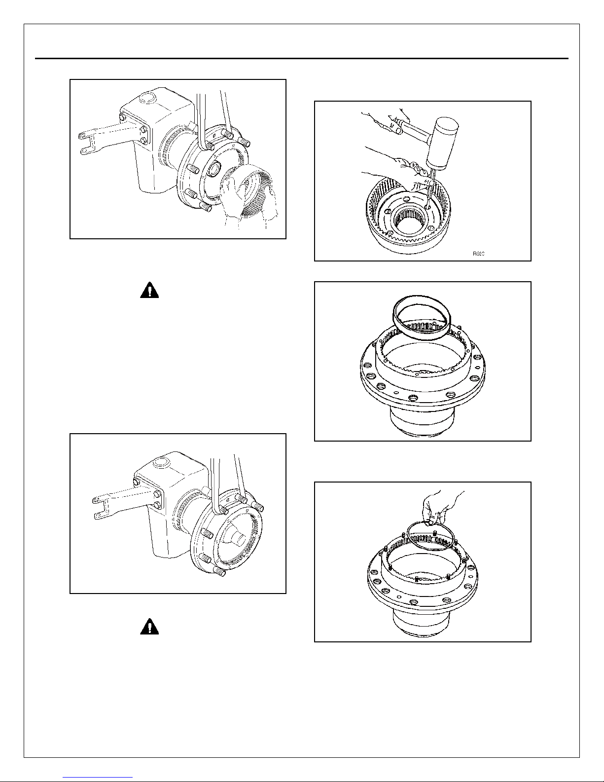
14. Use a rubber mallet and drift to remove the
ring gear hub taper bearing.
If necessary, install the CTI guide sleeve, part
number 5239, onto the spindle.
WARNING
To avoid serious
personal injury and damage to components,
take care when using lifting devices during
service and maintenance procedures.
Inspect a lifting strap to ensure that it is not
damaged. Do not subject lifting straps to
shocks or drop-loading.
13 . Use a lifti ng strap to re m o ve the hub
assembly. If bearing and seal have not been
taken out together with the hub, remove them
from the spindle. If necessary, remove the
spindle end ring.
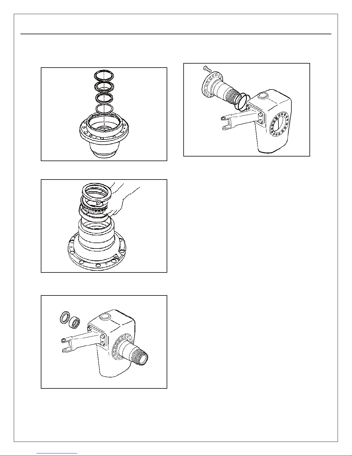
15. Remove bearing cup from hub.
For version C.T.I only
16. Remove the ci r clips.
WARNING
Use a rubber mallet for
assembly and
disassembly procedures. Do not hit steel
parts with a steel hammer. Pieces of a part can
break off and cause serious personal injury.
Page 15
Section 2
Disassembly
2-8
ISAS5 SEPTEMBER, 2017
For version C.T.I only
17. Remove outside ring. Remove outside seal,
the inner seal and the guide ring.
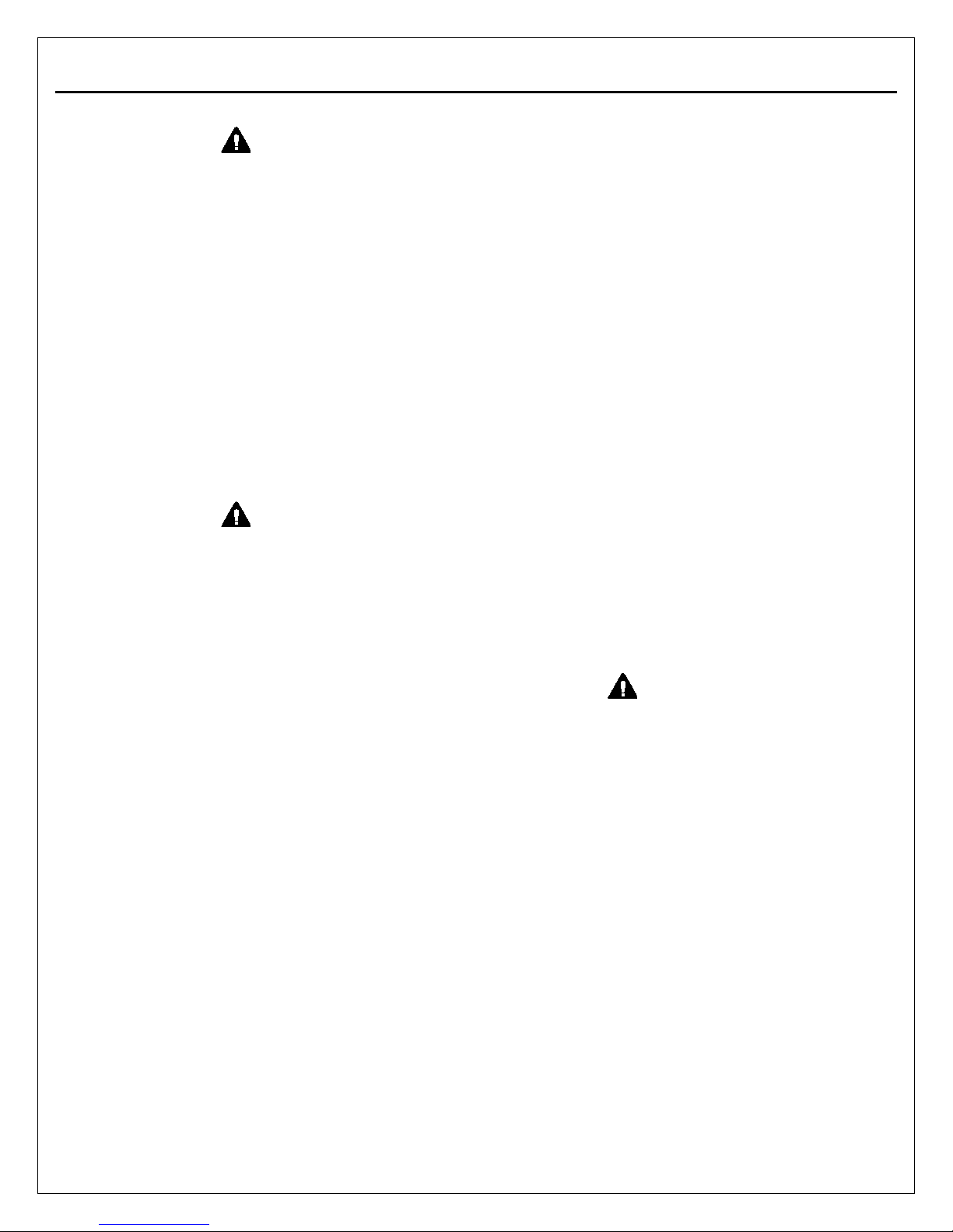
18. Return the hub. Remove seal, bearing cup
and bearing from hub.
20. If necessary, remove the spindle of the
knuckle.
19. Remove the oil seal and the bearing from the
knuckle.
Page 16
Section 3
Inspection
3-1
ISAS5 SEPTEMBER, 2017
WARNING
To prevent serious eye injury, always wear
safe eye protection when you perform vehicle
maintenance or service.
Tapered Roller Bearings
If the parts are clean and correctly lubricated, it is
rare to find damaged bearings during removal.
Therefore, avoid removing them because they
may be damaged by the puller.
Remove bearings with the following conditions:
1. Worn or damaged bearing surface.
2. Chipped bearing or damaged bearing surface
3. Incorrect lubrication.
4. Broken part in the mechanism.
WARNING
Solvent cleaners
can be flammable, poisonous and cause
burns. Examples of solvent cleaners are
carbon tetrachloride, emulsion-type cleaners
and petroleum based cleaners. To avoid
serious personal injury when you use
solvent cleaners, you must carefully follow
the manufacturer’s product instructions and
these procedures:
Wear safe eye protection.
Wear clothing that protects your skin.
Work in a well-ventilated area.
Do not use gasoline, or solvents that
contain gasoline. Gasoline can explode.
Use hot solution tanks or alkaline
solutions correctly. Follow the
manufacturer’s instructions carefully.
Bearing Assembly Precautions
If the bearing is new, unpac k it just before
assembly. If the bearing is reusable, clean it with
solvent-base cleaner and then oil it.
2. W hen a be ari n g ha s be en h eat e d fo r
assembly, apply a small amount of grease or
oil after assembly.
Seals
1. O-rings:
new O-rings.
2. Lip seals:
each removal. The bore must be carefully
deburred and greased before installing the
seal. The fitting of the seal on the seal
surface is always difficult; use care not to
damage the lip seals when installing them.
NOTE: It is better to install a seal with a press
than with a shock installer tool.
After removal, replace them with
Change lip seals with new seals at
Replacing a Wheel Stud
In case of a breakage or a stripping of a wheel
st u d i t mu s t be re p lace d . Gene r all y it i s
unnecessary to remove the hub to change it. Use
a drift and a hammer to remove the stud. The new
stud may be installed with a hammer or press fit.
Fasteners
For bolts with pre-applied microcapsulating after
removal use Loctite SR 242.
WARNING
Take care when you use
Loctite® to avoid serious personal
injury. Follow the manufacturer’s
instructions to prevent irritation to the eyes
and skin.
Tightening Torques
The tightening torques indicated in this manual
must be followed:
A tightening torque lower than indicated may lead
to a shearing stress and may break the bolt.
A higher tightening torque may lead to a plastic
deflection of the bolt and damage of the parts.
1. When it is possible, install the bearing parts
by cooling (in liquid nitrogen) or by heating (in
hot oil to 80°C [176°F]) instead of using a
press. A press is preferred to a shock installer
tool. The bore must be carefully deburred and
cleaned before assembly of the bearing.
Page 17
Section 3
Inspection
3-2
ISAS5 SEPTEMBER, 2017
Sealing of Mounting Surfaces
WARNING
Take care when you use
silicone gasket materials to avoid serious
personal injury. Follow the manufacturer’s
instructions to prevent irritation to the eyes
and skin.
Small amounts of acid vapor are present when
applying silicone gasket material. To prevent
possible serious personal injury, make sure
there is good ventilation in the work area. If
the silicone gasket material gets in your eyes,
flush your eyes with water for 15 minutes.
Have your eyes checked by a doctor.
Page 18
Section 4
Assembly
4-1
ISAS5 SEPTEMBER, 2017
WARNING
Observe all warnings and cautions provided
by the press manufacturer concerning press
operation to avoid serious personal injury and
possible damage to components.
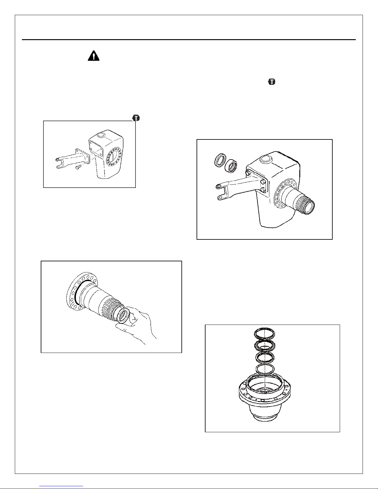
1. Install the steering arm. Use Loctite® 242 on
the screws. Install screws and tighten them to
200-258 lb-ft (271-350 Nm).
Installation
NOTE: Refer to Section 6 for drawings of the
tools specified in these procedures.
Hub Reducer
1. Apply Loctite 680 on the outer diameter of the
spindle ring. Install the spindle ring into the
end of the spindle.
4. Apply a bead of silicone sealing compound
on the face of the spindle.
5. Use Loctite® 242 on the screws. Tighten them
to 190 lb-ft (258 Nm).
6. Use a driver (part
number 5294) to insert a lightly greased
needle bearing into the spindle.
7. Use a seal driver (part number 5207) to
insert the seal.
8. Grease the lower edges of the seal.
9. Use Loctite® 510 on spindle and fit seal race
after heating it to 210-250°F.
2. Put one O’ring on the spindle.
3. Put the other O’ring in the groove of the
knuckle.
10. If the vehicle is equipped with central tire
inflation, follow steps A-C, below.
NOTE: Lightly lubricate the seal lips.
A. Install onto the hub the guide ring, the inner
seal use a seal driver (part number 5237).
B. Install the outside seal use a seal driver (part
number 5238) and the outside ring.
Page 19
Section 4
Assembly
4-2
WARNING
Components will be hot. Wear protective
gloves to avoid serious personal injury.
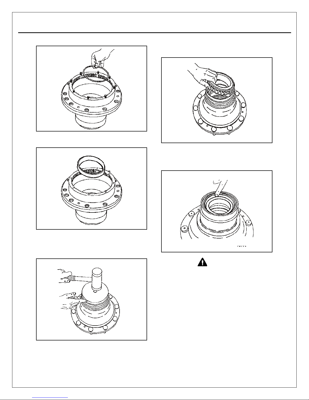
15. Heat the bearing cone to 175°F (79°C).
ISAS5 SEPTEMBER, 2017
C. Place the circlips on wheel hub.
11. Use the cup driver (part number 5046) to
install bearing cup onto the hub.
13. Install the bearing onto the hub. Pack the
bearing with grease. Refer to Section 5.
14. Use a seal driver (part number 5203) to install
the oil seal.
NOTE: Lightly lubricate the seal lips.
12. Use the cup driver (part number 5046) to
install bearing cup onto the hub.
Page 20
Section 4
Assembly
4-3
ISAS5 SEPTEMBER, 2017
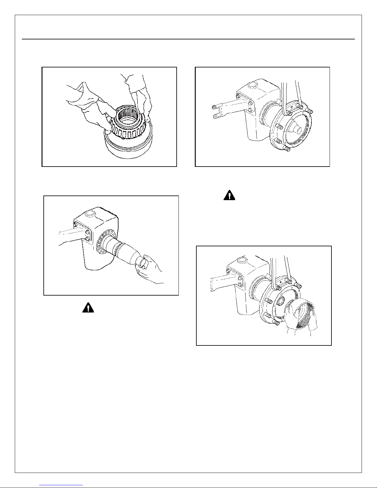
16. Wearing protective gloves, install the bearing
cone onto the ring gear carrier.
If the vehicle is equipped with central tire
inflation:
ber 5239) onto the spindle.
install the surface protector (part num-
17. With a lifting strap, fit the hub assembly onto
the knuckle. Hold the spindle in position.
If the vehicle is equipped with central tire
inflation:
Gear teeth can be sharp. Wear protective
gloves to avoid serious personal injury.
18. W earing protective gloves, install the ring
gear with its bearing onto the gear carrier.
Align the gear splines with the hub splines.
remove the surface protector.
WARNING
To avoid serious personal injury and
damage to components, take care when
using lifting devices during service and
maintenance procedures. Inspect a lifting
strap to ensure that it is not damaged. Do
not subject lifting straps to shocks or droploading.
WARNING
Page 21
Section 4
Assembly
4-4
ISAS5 SEPTEMBER, 2017
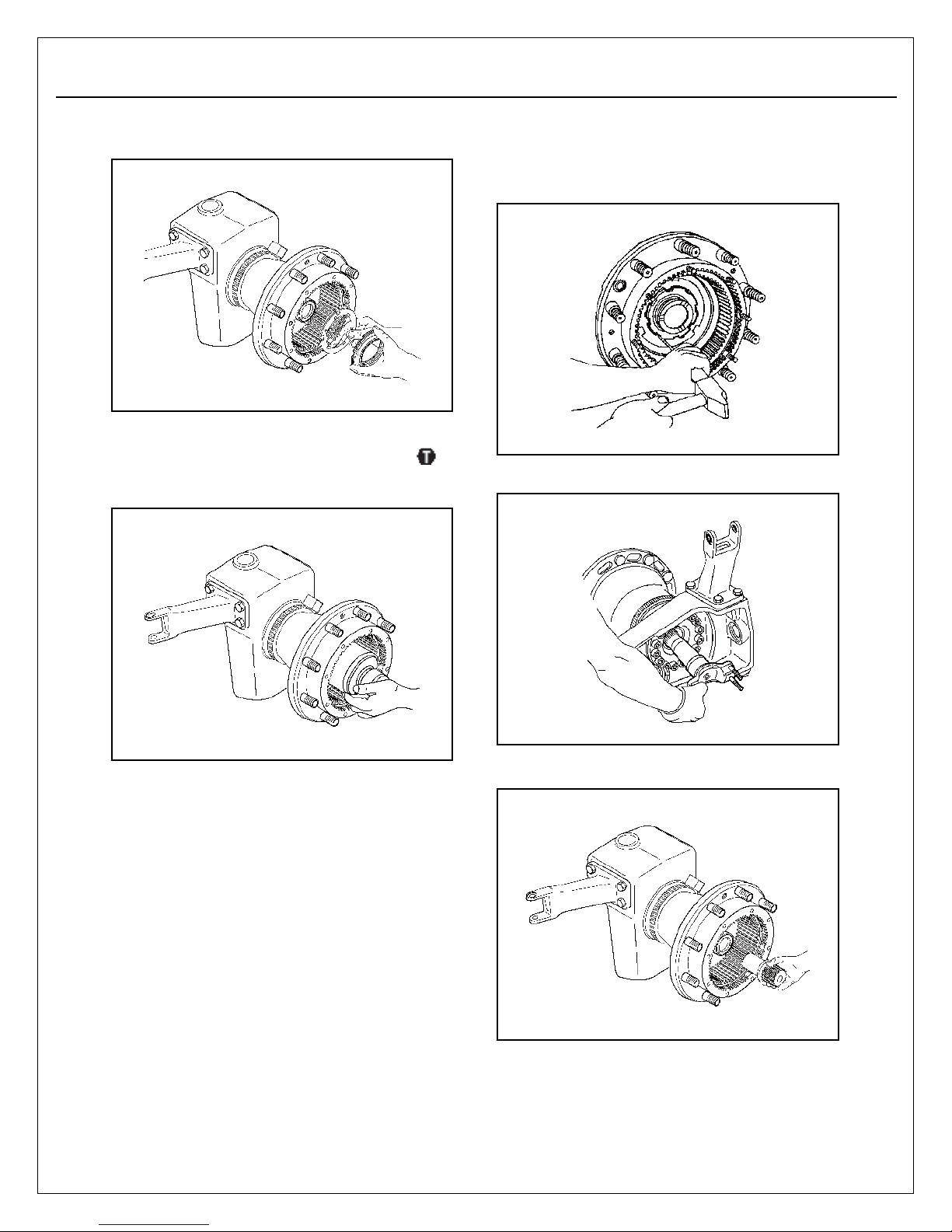
19. Install a new locking washer and a spindle
nut.
20. Use a spanner wrench (part number 5231) to
tighten the nut to 295 lb-ft ( 400 Nm).
Make sure the locking washer moves free
between the nut and the ring gear.
23. Bend the lock washer tangs into the grooves
in the wheel bearing adjusting nut. Keep the
tangs at a 45 degree angle to the ring gear
hub face.
24 . Inst all t he axle shaft.
21. While rotating the hub, tap ring gear to check
that the assembly is correctly fitted. Recheck
the spindle nut torque.
22. Back the spindle nut off 1/16 turn.
NOTE:
If the lock washer tangs do not align
with the adjusting nut, back off the
adjusting nut enough to align the tangs.
Do not bend the lock washer tangs back
too far. If the tangs are bent too far back,
the lock washer will not function
correctly.
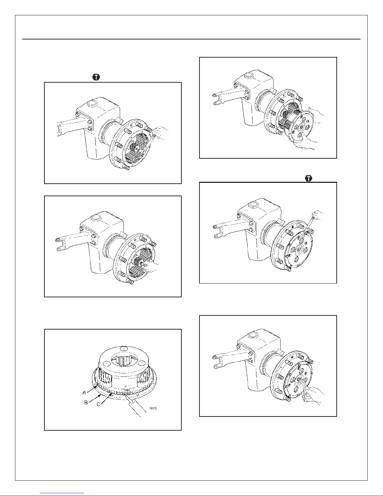
25. Fit coup ling and sun gear .
Page 22
Section 4
Assembly
4-5
ISAS5 SEPTEMBER, 2017
26. Maintain the sun gear with jet extractor of
bronze. Apply Loctite 242 to the threads of
the screw. Install screw and tighten to 152 ftIbs (203 Nm).
27. P la c e th r us t b ut t on .
29. Install the planet gear carrier cover assembly.
30. Use Loctite® 242 and install the cover screws.
Tighten to 44-55 lb-ft (60-75 Nm).
28. Install silicone sealing compound in the
groove C between the splines A and the face
B of cover.
31. Install the adjusting screw until it contacts the
shaft. Unscrew by 3/4 turn max to give 0.020-
0.060 inch (0.5 mm to 1.5 mm) shaft end play.
Page 23
Section 4
Assembly
4-6
ISAS5 SEPTEMBER, 2017
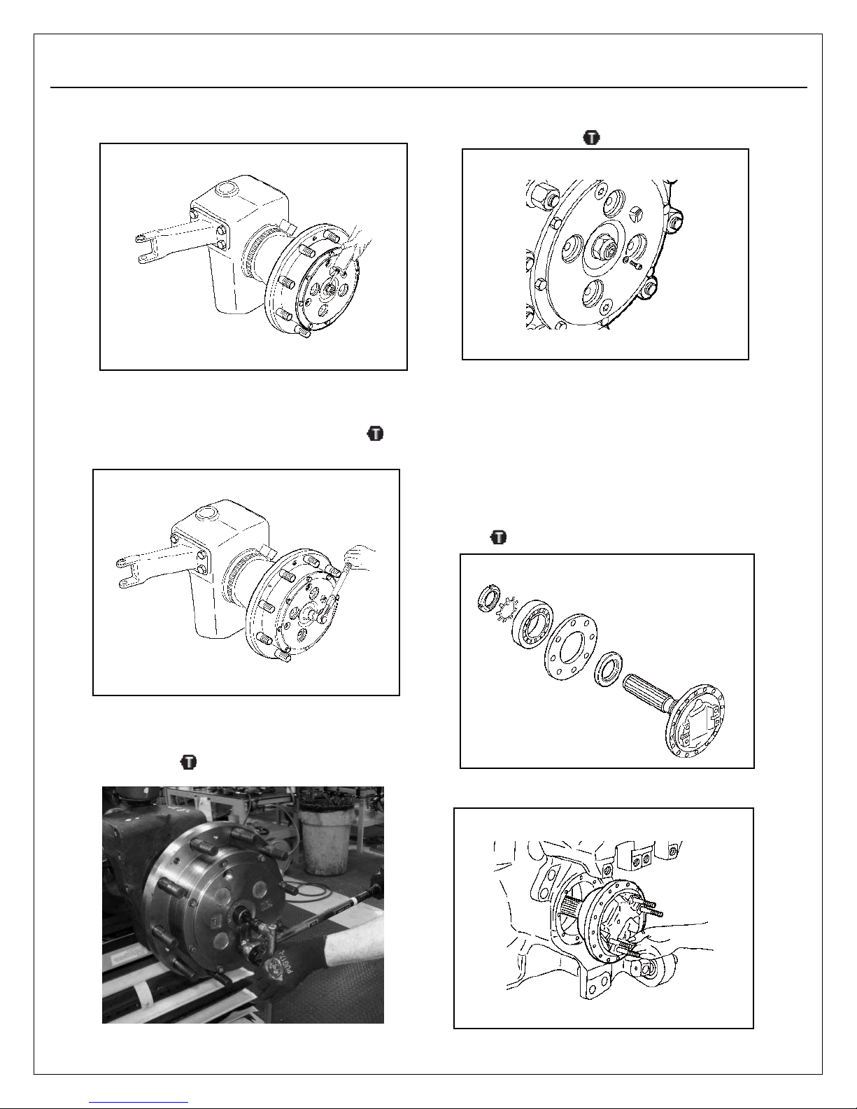
.
35. Install copper seal and level screw. Tighten to
b (12 Nm).
8 ft-l
Differential Halfshaft
Refer to the differential exploded view in
Section 1.
1. Install the oil seal into the seal housing.
2. Install the seal housing, the bearing, a new
lock washer and nut onto the shaft.
3. Tighten the nut to 147-184 lb-ft (200-250 Nm).
Then tighten it to next slot and lock it.
4. Engage the shaft assembly in the carrier
housing. The dog clutch must be engaged.
Page 24
Section 4
Assembly
4-7
ISAS5 SEPTEMBER, 2017
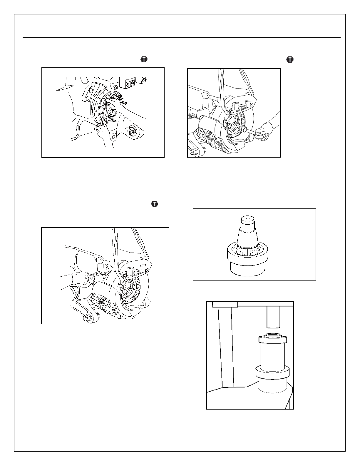
5. Use Loctite® 242 and install the 8 screws.
Tighten to 22-30 lb-ft (30-41 Nm).
Brake Disc
1. Install the disc and the brake caliper. Use
Loctite® 242 on the 4 caliper screws and
tighten to 369-480 lb-ft (500-651 Nm).
2. Use Loctite® 242 on the 16 disc screws and
tighten to 22-30 lb-ft (30-41 Nm).
Su
spension
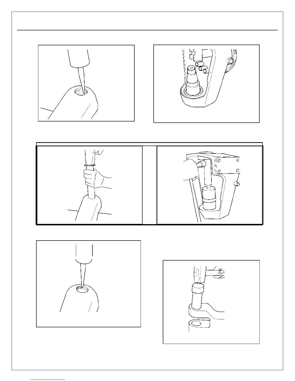
1. Install the king pin in the tool (part number
5293).
2. Press the king pin into the upper wishbone.
Page 25
Section 4
Assembly
4-8
WARNING
Take care when you use adhesive materials to
avoid serious personal injury. Follow the man-
ufacturer’s instructions to prevent irritation to
the eyes and skin.
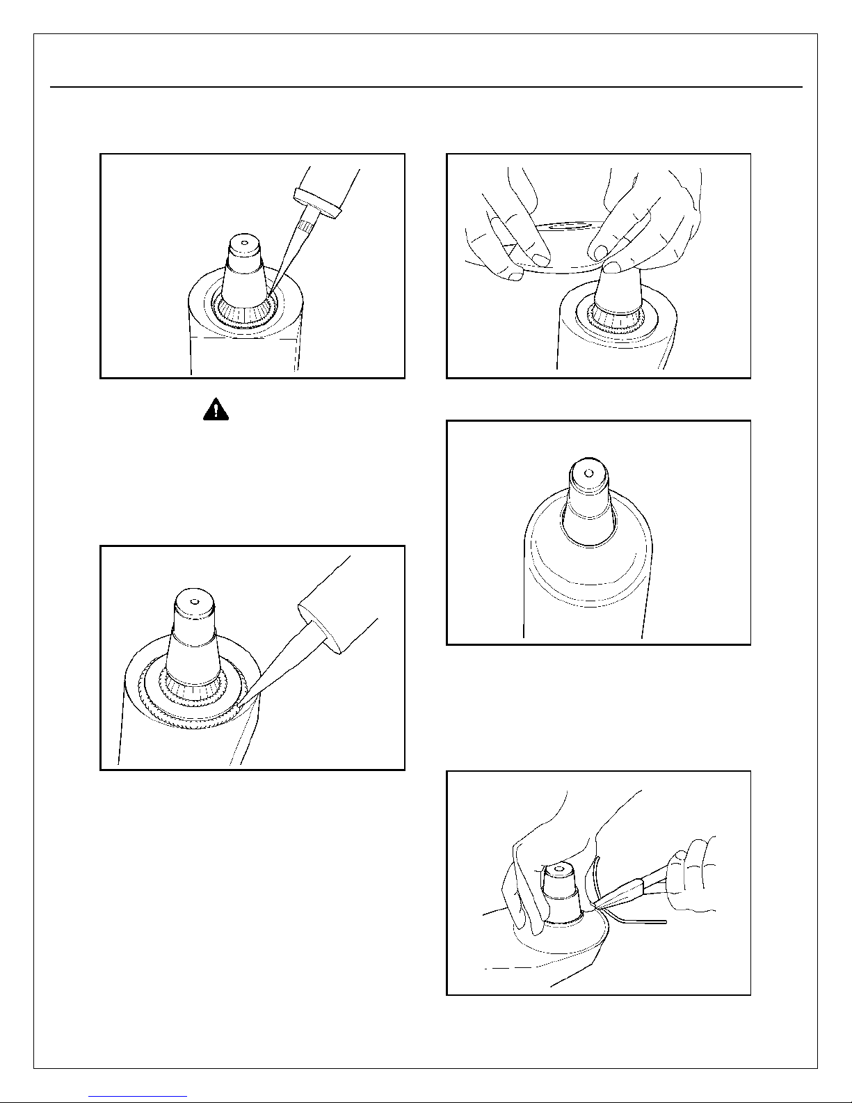
4. Apply a layer of adhesive (Terostat 8590) in
the groove on the upper wishbone.
6. Carefully slide the seal into position.
7. Maintaining the seal in place, using a lock
wire, make one pass around the seal in the
groove area, using a twisting action tighten
the wire until it is holding the seal firmly in
place, but not cutting rubber seal. Position the
twist so it will not puncture the seal.
ISAS5 SEPTEMBER, 2017
3. Install the internal circlips. Apply a bead of
grease around the king pin.
5. For ease of assembly, preaper the king pin
seal as shown below.
Page 26
Section 4
Assembly
4-9
ISAS5 SEPTEMBER, 2017
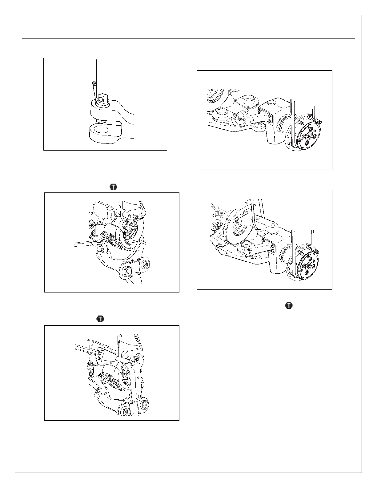
8. Apply grease into the upper wishbone.
9. Install the core plug into the upper wisbone.
11. Install the king pin into the knuckle.
12. Pr e s s i n to p l ac e.
10. Apply a bead of silicone sealing compound on
the core plug.
13. Proceed as with the upper wishbone. Refer to
steps 3 - 10.
14. Apply Loctite® 641 in the bores of the upper
wishbone. Press in the straddle bearing with
a mallet.
Page 27
Section 4
Assembly
4-10
ISAS5 SEPTEMBER, 2017
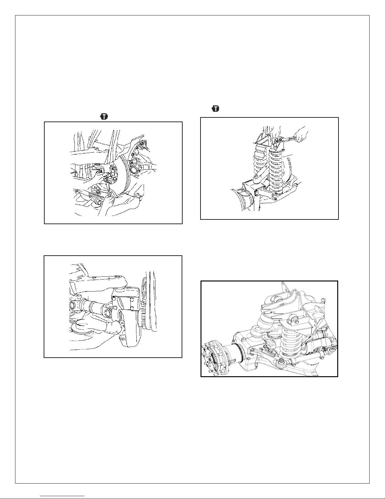
15. Install the int ernal circlips.
NOTE: For installing straddle bearing into the
axle housing, refer to steps 11-12.
16. Install the lower wishbone. Apply Loctite®
242 to the screws and tighten to 369-480
lb-ft (500-651 Nm).
18. With a lifting strap, install the wheel end
assembly into the lower wishbone. Handtighten the lower king pin nut.
19. Install the upper control arm. Hand-tighten the
upper king pin nut.
17. Install the upper wishbone. Apply Loctite
242 to the screws and tighten to 369-480 lb-ft
(500-651 Nm).
®
20. Tighten the lower and upper king pin nuts to
572-608 lb-ft (775-825 Nm).
Page 28
Section 4
4-11
ISAS5 SEPTEMBER, 2017
Cardan Joint
NOTE: Steering ISAS uses double cardan
joints with stud and nut fasteners. Nonsteering ISAS uses single cardan joints with
capscrew fasteners.
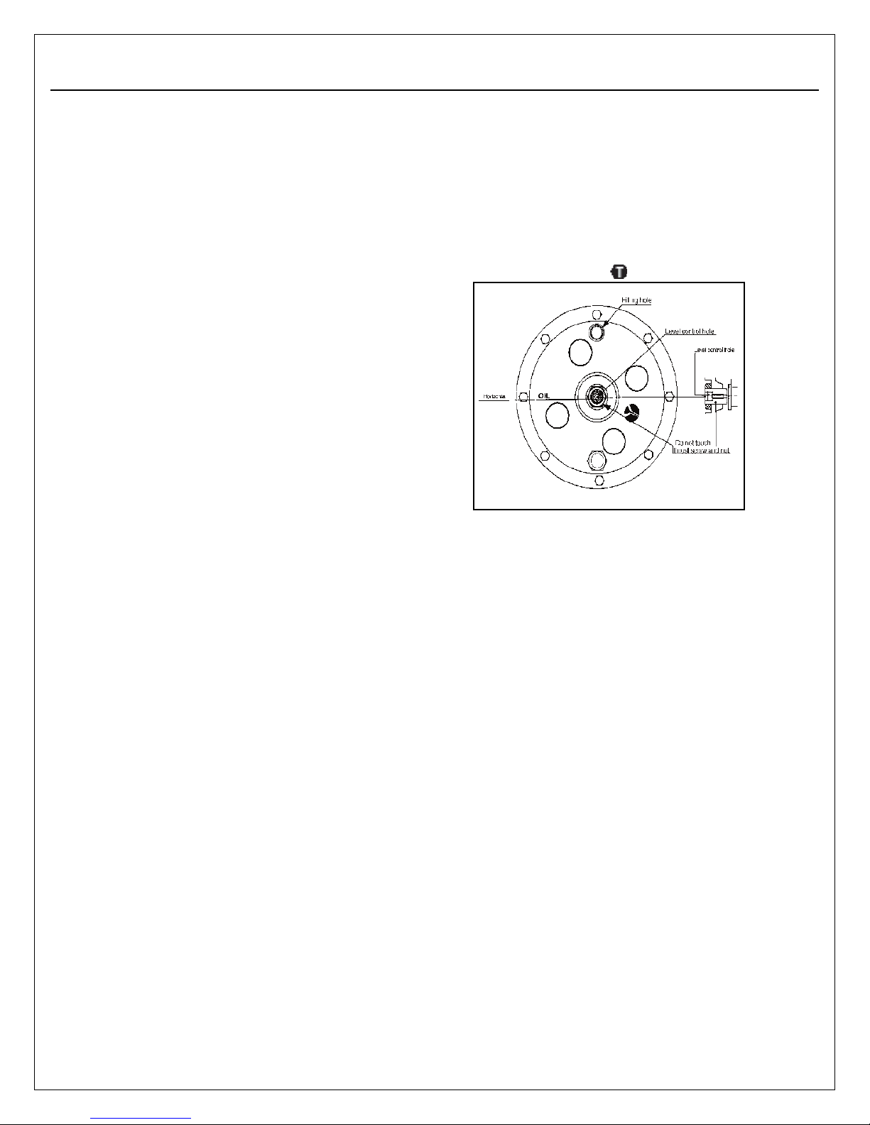
1. Engage the cardan joint on the housing
side. Fit fasteners and tighten to 44-55 lb-ft
(60-75 Nm).
2. Align the wheel end with the axle.
Fit fasteners on reducer side and tighten
to 44- 55 lb-ft (60-75 Nm).
Shock Absorber
(Top Post Shock)
1. Install the springs and shock absorber. Install
the upper spring cap. For ease of assembly,
main t a in with tool (p a r t number 5295).
Tighten the nuts to 90 ft-lbs (150-170 Nm).
(Top Cross Bolt Shock)
2. Install the spring & shock absorber.
Install the upper shock mounting hardware.
Tighten to 310-400 lb-ft (420-542 Nm).
Page 29
Section 5
ISAS5 SEPTEMBER, 2017
Lubrication
Lubrication
For more information on lubrication standards and
specifications, refer to AxleTech Maintenance
Manual 1, Lubrication.
Oil Change
Differential
First oil change: After 100 hours or 2500 miles.
Lubricant level check: Every 3000 miles (4800
km) or semi-annually.
Oil change interval: Every 24,000 miles (38,600
km), 24 months or 2000 hours.
Lubricant Quality
Due to the duty imposed upon the equipment, we
recommend a multigrade lubricant 80W/90 with
service level API GL5 and approved as meeting
US MIL L 2105 D specification. All lubricants used
must be compatible between them. Some oils can
deteriorate seal materials. Avoid mixing two different oil types, even if from the same trade name.
Refer to AxleTech Maintenance Manual 1.
Draining
Drain oil when vehicle is near normal operating
temperature. Clean the drain plug.
Hub Reduction
First oil change: After 50 hours.
Lubricant level check: Every 3000 miles (4800
km) or semi-annually.
Oil change interval: As required by other main-
tenance actions (such as re-packing wheel bearings).
Filling Procedure
The vehicle must be on a level floor.
Ensure the lower plug is installed.
Fill the wheel end until fluid flows from the oil hole.
Allow enough time for the fluid to flow through the
complete assembly.Clean plug and tighten it to
18-26 lb-ft (25-35 Nm). Tighten control level
screw to 8 lb-ft (12 Nm).
Lubricant Capacity
Lubricant capacity is given as a guideline only.
The oil level only determines the lubricant capacity needed according to the unit.
Inner Wheel Bearings
Remove, clean, dry and repack every 24,000
miles (38,600 km). Use AxleTech STC 05-203 per
MIL-PRF-10924.
Suspension Bushings
Regrease every 3000 miles (4800 km) or quarterly. Use a multipurpose lithium soap grease.
Use AxleTech STC 05-203 per MIL-PRF-10924.
The oil change interval varies according to the
type of vehicle and operating duty.
Halfshaft Cardan Joints
Regrease every 3000 miles (4800 km) or quarterly. Use a lithium soap grease with a consistency of Class 2 or better. Use AxleTech STC 05203 per MIL-PRF-10924. Do not use grease with
MoS2 additive.
Page 30
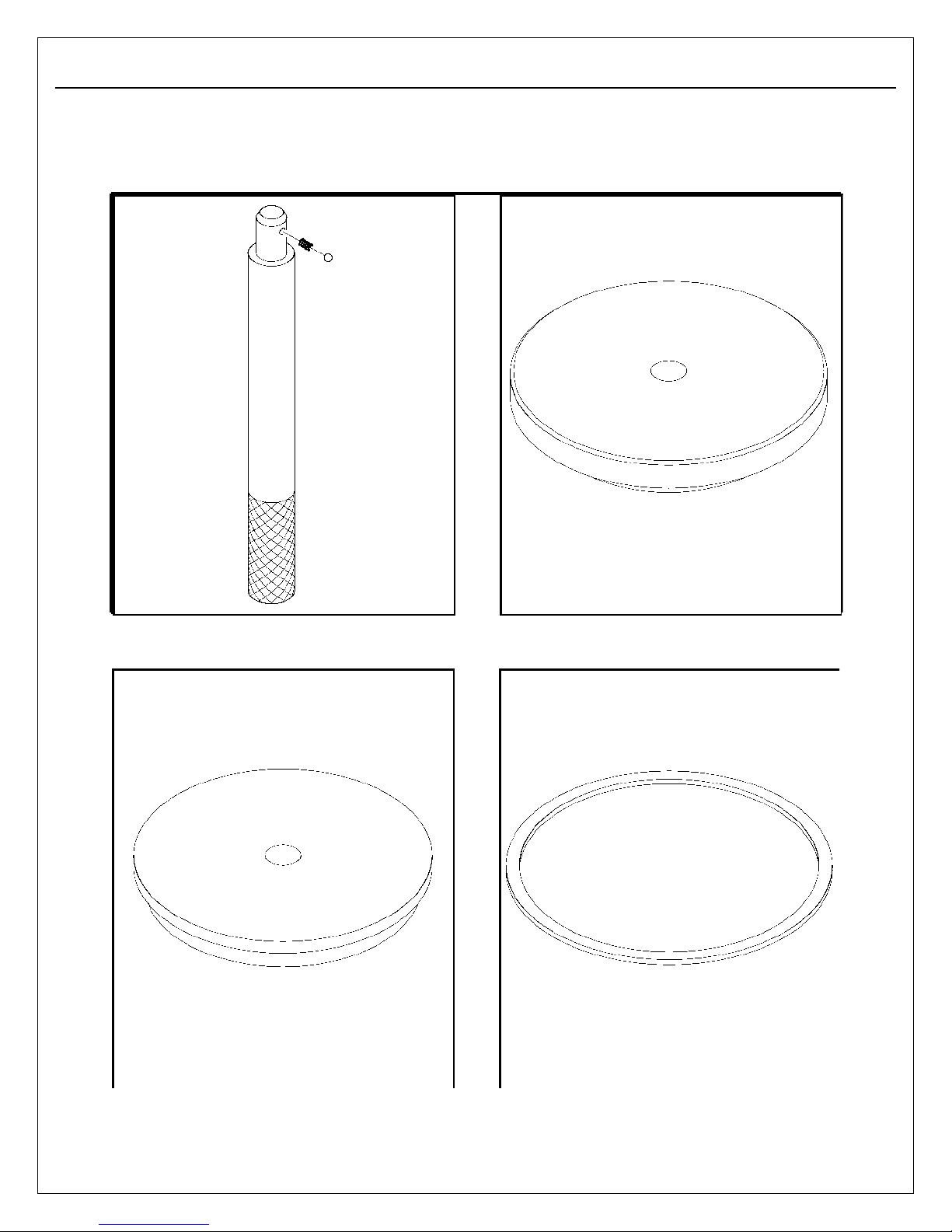
6-1
Special Tools Drawings
Driver handle - 5021
Hub seal driver - 5203
Cup driver - 5046
Washer - 5204
ISAS5 SEPTEMBER, 2017
Section 6
Special Tools
Page 31
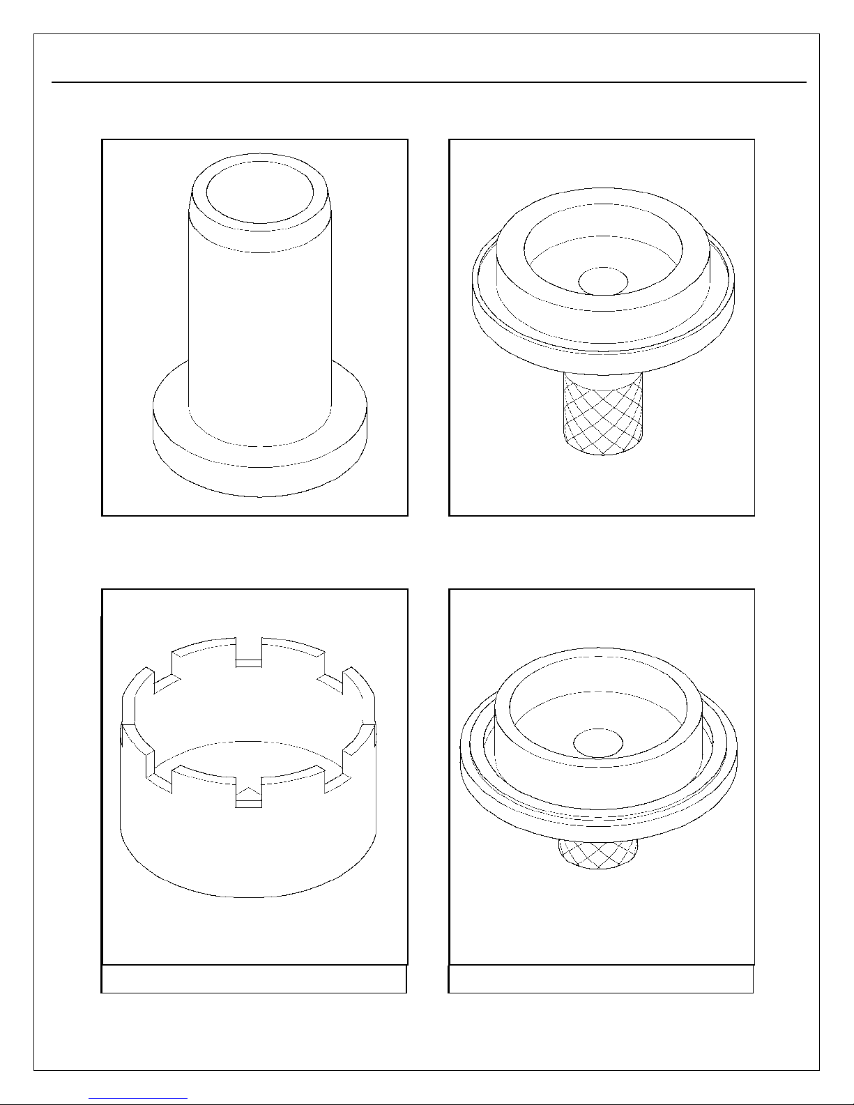
Seal driver - 5207
CTI seal driver - 5237
Spanner wrench - 5231
CTI seal driver - 5238
ISAS5 SEPTEMBER, 2017
6-2
Page 32
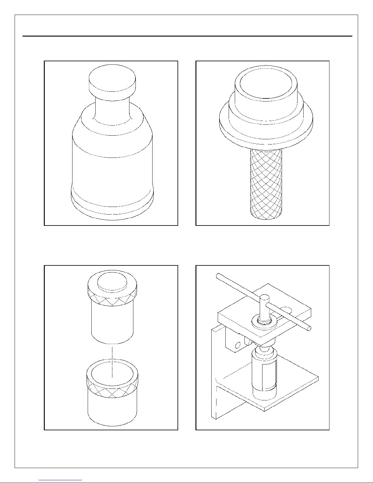
Section 6
Special Tools
6-3
Protector - 5239
Bearing driver - 5294
King pin muff - 5293
Shock absorber clamp - 5295
ISAS5 SEPTEMBER, 2017
Page 33

REVISIONS
Updated torque requirements from 155lb-ft to 90-110 ft-lb on page 4-6 #33 per Tammy Marsh.
1
T. Betena
09/20/2017
ISAS5 SEPTEMBER, 2017
 Loading...