

Page 1

AXIS Dyno
USER MANUAL
MODEL
Moto VX-12
Page 2

2
Page 3

Table of Contents
Page
Introduction
- Dimensions & Weight
5 - Warning, Cautions and Notes
Axis Instalation
- Outdoor
- Dyno room
AXIS Dyno Operation
- Software Instalation
- Graph Legend Customization
Troubleshooting
- Axis Manager disappear
3
Page 4

4
Page 5

Introduction
The Moto VX-12 AXIS Dyno will come to your workshop in wooden crate package
SAE
Metric
Remarks
Width
38”
97cm
Length
114”
290cm
Height
50”
127cm
Volume
150 CFT
4 CBM
Weight
1600 Lbs
725kg
Shipping Insurance purpose.
Please check the package condition before sign on the bill of lading, check for any sign of
damage, drop, puncture,etc.
We strongly recommend that you inspect the shipping crate for potential damage.
We had a case where the shipping company put a fragile label over a fork puncture and went
unnoticed until it was opened. The shipping company denied the insurance claim.
If you see damage, it is important to take pictures and document fully for the claim.
Unloading.
Use forklift with capacity more than weight listed above.
Note:
5
Page 6

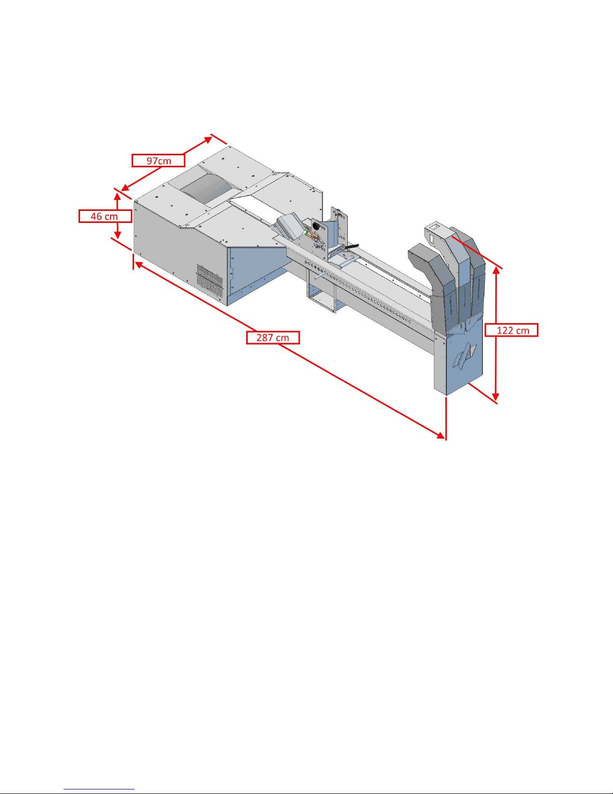
Introduction
The Moto VX-12 AXIS Dyno dimensions
AXIS Dyno Moto VX-12
SAE
Metric
Remarks
Width
38”
97 cm
Length
114”
290 cm
Height
50”
127 cm
Weight
1200 Lbs
545 kg
Max. Torque
1000 ft-lb
1356 Nm
Max. Speed
160 MPH
250 Km/h
Dyno Display
Wheelbase
40” ~ 84”
100 cm ~ 213 cm
Shaft to shaft
Inertia Adjustability
250 lbs ~ 950 lbs
114 kg ~ 430 kg
Bike + Rider
Power Requirement
Input AC 100 ~ 240 VAC, 50/60Hz, 2.0-1.0A
Output 15VDC 9.6A, 144W Max.
6
Page 7
AXIS Installation
AXIS Chassis Dyno placement
Outdoor
WARNING
Keep clear of air inlet, any debris sucked will be go toward air outlet at the front of the vehicle,
use safety glasses.
7
Page 8

Indoor, Dyno Room
Install air duct from outside of the dyno room to the inlet of the air turbine.
8
Page 9

Bike ramp sample drawing,
9
Page 10
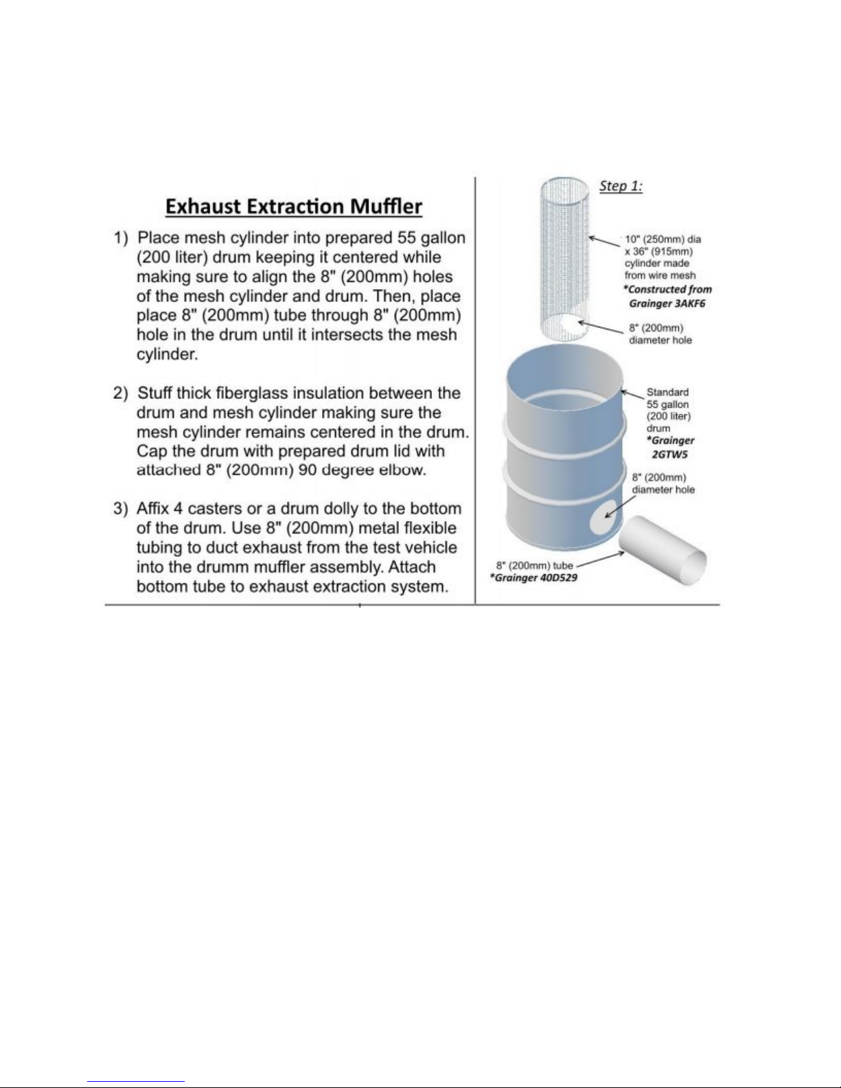
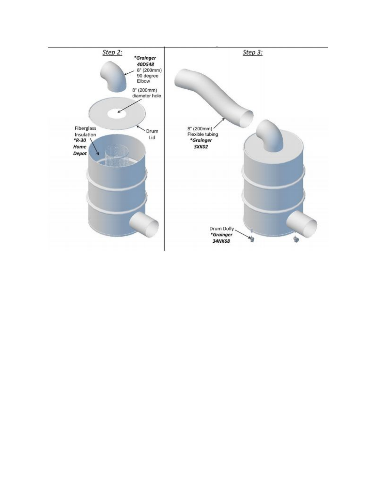
Exhaust options
Exhaust gases must be expelled outside. If you need an exhaust db killer to suppress sound,
please contact your local supplier for design plans to help you make it.
10
Page 11
11
Page 12

Computer Control
We recommend follow the computer specifications to run the Axis software.
Here is a list of the major components needed:
1. Hard Driver - SSD at least 250 GB or higher
2. Dedicated Graphics with 2GB RAM minimum (Nvidia GTX 1050ti or
higher)…..absolutely no intel onboard graphics. These will pull power away from processor and
cause issues with data collection.
3. Intel i5 or higher processor (No U Series Processors) - We custom build our computers
and use the K Series which is an unlocked and overclockable processor.
4. 8 GB of DDR4 RAM 2133 mhz or higher
Sample : Dell Inspiron 15 5000 Gaming, Lenovo Legion Y520 – GTX 1050TI
We recommend good lighting for the workspace, good air ventilation and internet access for the
dyno computer to be able to email and share charts and results.
12
Page 13

AXIS Visual Software
AVS Axis Visual Software.
Software Installation
AXIS Dyno Software and updates will be send via email.
13
Page 14
Dyno Manager
Follow these steps to set your Dyno Manager calibration figures:
- In the drop down menu, select which Model dyno you are using.
“Default-MC” for motorcycle, “Default-UTV” for UTV, and “Default-TRI” for trike.
- Put the Drum at TDC mark, Current Input voltage 0.47 ~ 0.53 click Zero button.
- Click “Calculate.” The value in the “Gain” box will change.
- Calibration numbers are now set.
14
Page 15

If your Dyno electronics are connected, you should see the Hardware showing Connected.
Run Start Speed?
Run Start RPM?
Correction Factor?
Setting up the Inertia Disks
The Axis Dyno inertia can be adjusted to reflect the total weight being accelerated.
Total weight = vehicle + fluids + cargo + passengers
Disk Weight Chart
Weight (Kg)
Weight (lbs)
# of Disks
104
230
0
129
285
1
156
345
2
181
400
3
208
460
4
235
520
5
263
580
6
288
635
7
315
695
8
342
755
9
369
815
10
Note: Use spacers with 5 disks or less
18 in dia drum, 80t driver, 28t driven, and 17 in dia disks
When changing inertia discs, it is very important that they are aligned correctly in order to
maintain balance. The punch mark on the ½” stud needs to be aligned with the punch mark on
each disk and must be oriented vertically before tightening.
15
Page 16

16
Page 17

Perform an inspection before loading a vehicle
● Check the fluids - oil, coolant and fuel levels, leaks.
● Check the tires - overall condition, pressure and tire speed rating.
● Check the chain - tension and lubrication.
● Overall bike inspection, fasteners.
Loading up your vehicle
Secure front wheel
Centering rear wheel
Strap down the bike, put the strap down diagonal front of the motorcycle, equal tension both left
& right.
1.c.4 - Pre-run Checklist
● Check bike alignment on dyno
● Check tie-down straps
● Check the dyno - ensure drum rotates freely and the dyno is free of debris
● Ear and eye protection
● Staying clear - do not stand behind the dyno during operation
● Warm up - both bike and dyno need to come to operating temperature for best results
1.c.5 - Making your first run
Focus on repeatability
Nothing connected to the bike
The Dyno result to the rear wheel Speed
- Horse power
- Dyno Torque
1.d - Getting More Out of Your Axis Dyno
17
Page 18

1.d.1 - RPM
Injector pickup
- Attach AXIS ground clip to the best ground position on the vehicle.
- Locate fuel injector position, remove wire connector, match injector connector and install
the injector signal pick-up cables, swap the connector end if the rpm not displayed.
Inductive pickup
- Attach to high tension ignition cable, (spark plug cable)
Calculated RPM
1.d.2 - AFR
AFR probe install
AFR Signal
1.d.3 - Auxiliary inputs
18
Page 19

Maintenance
Maintenance should be done after every 80 hours of use. All bolts should be checked for
loosening and thread locker added if needed. Remove all top covers for maintenance.
2.a.1 - Belt Tension
Belt tension should not need to be changed but can be checked using one of the following:
● Pluck the belt like a guitar string and measuring the frequency using a phone guitar tuner
app. Belt tension should be between 62 to 70 Hz.
● The belt should deflect 5/16” with a 30 lb force at the center of the span.
If the belt tension is wrong, use the following procedure:
● Loosen the two 3/8 bolts located behind the tensioner and next to the drum
● Adjust the belt tension from the top using the long 1⁄2-13 bolt
Tighten the 3/8 bolts and check the tension again.
● Repeat if necessary.
2.a.2 - Bearings and Bushings
It is recommended to lubricate the bearings every 80 hours of use. A high speed and
temperature lubricant (e.g. Lithium base NGLI #2) is recommended.
The bearings are shown for reference.
19
Page 20

The keyless bushings on blowers should be checked and re torqued to ____(spec).\
2.a.3 - Centering The Drum
If at some point, the drum is removed from the dyno chassis for service, follow these instructions
to re-center the drum.
20
Page 21

2.a.4 - Rust Treating The Drum
21
Page 22

Section 3 - Support
3.a - Dyno Electronics
3.a.1 - AFR Setup
22
Page 23

Setting up your AFR signals in the Axis Dyno software (Configure Settings Menu):
Value
AFR 1
AFR 2
Wire Pink/Yellow
Purple/Yellow
Input AIN07
AIN00
Input Delay
0.00
0.00
Low Volt Reading
0
9.4
9.4
High Volt Reading
2.5
17.2
17.2
Scale Factor
1 1
23
Page 24

24
Page 25

3.Chassis Coil Replacement
3.a.4 - Cleaning Reflective Disk
If your graph for dyno runs presents wavy symptoms such as these:
Check your graph when plotting Speed Vs Time if it shows a graph with large anomalies such
as these then you will need to perform the reflective disk cleaning process.
25
Page 26

Follow these steps:
1. Loosen set screw on reflective disc collar
2. Back collar up as far as it can go so you can access the front of the reflective disk
3. Spin the drum as you hold a cloth with alcohol on it to clean the pads on the disc
4. Once clean move the collar and disc back up until the disk is close to .030” or 0.762mm
away from the chassis disk
1. 2.
3. 4.
26
Page 27

Chassis Board Replacement
To replace the chassis board on the Axis VX12, please take the following steps:
1. Disconnect Dyno Power and Data Cables
2. Remove Left Side Roller Cover
3. Remove Three Connectors From Chassis Board
4. Remove Two Phillips Head Screws Holding Board
5. You may need to remove the screws holding the square board in place and shift over the
reflective disk collar to gain access to the screws in Step 4
6. Remove and Replace Chassis Board
7. Reverse steps to reassemble
1. 2.
3 & 4.
5. 6.
27
Page 28

Drum Board Replacement
Follow these steps:
1. Remove the top panel from the left side of the drum (when viewed from behind)
2. Locate the red drum board mounted on the side of the drum
3. Remove the black, 3 pin Molex connector from the drum board
4. The drum board is affixed to the drum by two Phillips head screws and two nylon
spacers
5. Remove the two Phillips head screws while being careful not to drop the spacers
6. Loosen the 5 flathead screws on the green terminal block, then pull back on the wires to
release the board
7. To replace the drum board with a new one, follow the steps in reverse order while paying
particular attention to the arrangement of wires into the green terminal block.
1. 2. 3.
28
Page 29

5.
29
Page 30

6.
30
Page 31

Labjack Replacement
Follow these steps:
1. Remove the 8 screws (4 on each end) from the faceplates of the electronics box.
2. Bend the faceplate containing the USB plug down as shown below.
3. Slide the top body of the box off the bottom plate and over the faceplate as shown
below.
4. Remove the USB, smoothing box, and power filter board from the Labjack. The
smoothing box and power filter board are held on with Velcro. See below.
5. Loosen all terminals on the Labjack and pull wires back out of terminal slots.
6. Remove Labjack from bottom plate. It is held to the bottom plate with Velcro.
7. Add mating Velcro strip to bottom of Labjack, then place Labjack in position on the
bottom plate.
8. Replace wires into the correct terminal slots, and tighten each. See image below for
wire positions. Note that all terminals marked “VS” are connected and all terminals
marked “GND” are connected and which of these slots are utilized may vary from box to
box.
9. Reassemble box following steps 1-4 in reverse order.
31
Page 32

Smoothing Box Replacement
Follow these steps:
1. Remove the 8 screws (4 on each end) from the faceplates of the electronics box.
2. Bend the faceplate containing the USB plug down as shown below.
3. Slide the top body of the box off the bottom plate and over the faceplate as shown
below.
4. Disconnect the 4 pin clear connector and remove smoothing box, which is held on with
Velcro.
5. Add Velcro to new smoothing box, place on Labjack, and plug in 4 pin connector.
6. Reassemble electronics box by following steps 1-3 in reverse order.
32
Page 33

Splicing the Load Cell Cable
Follow these steps:
1. Cut each end of the splice to the desired length. Note that roughly 1” will be lost through
the splicing process.
2. Cut a 4” section of ½” adhesive lined shrink tubing and slide it over one of the ends and
out of the way.
3. Strip back 2” of insulation from each end of cable.
a. Start by making a circumferential cut into only the insulation.
b. Next, score the end piece of insulation linearly along the entire length.
c. Peel back the insulation to reveal the shielding.
4. Peel back the shielding to reveal a white and red wires as well as a bare wire and two
more wires in another layer of shielding.
5. Peel back the second layer of shielding to expose two more wires; green and black .
6. Cut away excess shielding up to the insulation.
7. Repeat process for both ends of the splice to get to the point pictured above.
8. To keep the splice small, offset the wires by trimming each ¼” more than the last as
pictured.
9. Trim the wires of the other side of the splice in opposite order of the last so that the wires
match up as shown above.
33
Page 34

Checking The Load Cell
Follow these steps:
1. Check the Wheatstone bridge
a. Set your multimeter to ohms (Ω). If your meter does not auto scale, set it to the
just high enough to read 350 Ω. This will likely be the 2k or 2000 setting.
b. Referring to the picture above, place one of the probes on terminal 1 (red wire).
c. Place the second probe on terminal 2, 4, and 5 recording the resistance at each
terminal. The resistances should match the table below.
2. Check Static Output
a. Set your multimeter to the millivolt (mV) setting.
b. Check and record the voltage between terminals 1 and 5. A good load cell will
read very close to 00.0mV at rest with no vehicle loaded.
3. Check Dynamic Output
a. Set your multimeter to millivolt (mV) as with the last test.
b. Place the multimeter pins on terminals 1 and 5 again.
c. Have another person rock the drum back and forth a couple inches (careful not to
pinch fingers) each way while you watch the multimeter display.
d. Record the high and low numbers seen while rocking the drum.
e. Depending on the force applied in rocking, the readout should be ~±.3mV.
Wheatstone Bridge Readings
Terminals
Resistance
1>2
~280Ω
1>4
~280Ω
1>5
~350Ω
34
Page 35

3.b - Dyno Mechanical
3.b.1 - Belt Tension Adjustment
Belt tension should not need to be changed but can be checked using one of the following:
1. Pluck the belt like a guitar string and measuring the frequency using a phone guitar tuner
app. Belt tension should be between 62 to 70 Hz
2. The belt should deflect 5/16” with a 30 lb force at the center of the span
If the belt tension is wrong, use the following procedure:
1. Loosen the two 3/8 bolts located behind the tensioner and next to the drum
2. Adjust the belt tension from the top using the long 1⁄2-13 bolt
3. Tighten the 3/8 bolts and check the tension again. Repeat if necessary.
3.b.2 - Blower Belt Replacement
3.b.3 - Centering The Blower Wheel
3.b.4 - Centering Drum
3.b.5 - Changing Blower Bearings
3.b.6 - Changing Drum Bearings
3.b.7 - Rust Treating The Drum
35
Page 36

3.c - Dyno Software
3.c.1 - Adding Your Logo to Graphs
3.c.2 - Calibration
1. With no bike on and load cell at top dead center, take note of the dyno torque in settings.
(Dyno torque will only show up without speed if you manually select it in settings and
watch in the settings screen. Dyno torque should display where the yellow box is in
picture 2)
a. If your dyno torque is within +-5 of 0 with no bike on and load cell TDC, then your
low number is good and does not need adjusting and you may skip to step 2.
b. If your dyno torque falls outside of this range, then the zero torque value should
be adjusted for maximum accuracy.
c. In settings select one of your AUX channels and change the settings to match the
settings in the orange box in picture 1 below.
d. With these settings entered, a non-zero value should show up in the green box in
picture 1 below. Note this voltage.
e. Navigate to the 'AVS 1.1' folder by right clicking the 'AXIS 1.1' desktop icon and
selecting "Open File Location."
f. From within the 'AVS 1.1' folder open the folder named 'AXIS-SETTINGS.'
g. Open the file named ‘baseconfig.txt.’
h. Replace the number next to the label “vLi” with the number from step (d). The
number in question is shown in the blue box in picture 3 below. (Note, be sure
not to change anything but the number itself. Any change to the syntax such as
deleting a comma or parenthesis will make the software crash or not boot up
correctly. Attached is a picture of the number that needs to be replaced.)
i. Repeat step 1 to ensure that your dyno torque now rests within a few ft-lb’s of 0.
If it does, move on to step 2.
2. To adjust your resulting HP and torque values, navigate back to the baseconfig.txt file as
described in steps (e) through (g) above.
3. Adjust the value shown in the purple box below in picture 3. Increasing this number will
increase your overall HP and torque values, and lowering it will decrease your numbers.
4. After making an adjustment, do a couple runs with a known vehicle and evaluate the
results. You’ll likely have to make a few adjustments to get the numbers correctly dialed
in.
36
Page 37

37
Page 38

38
Page 39

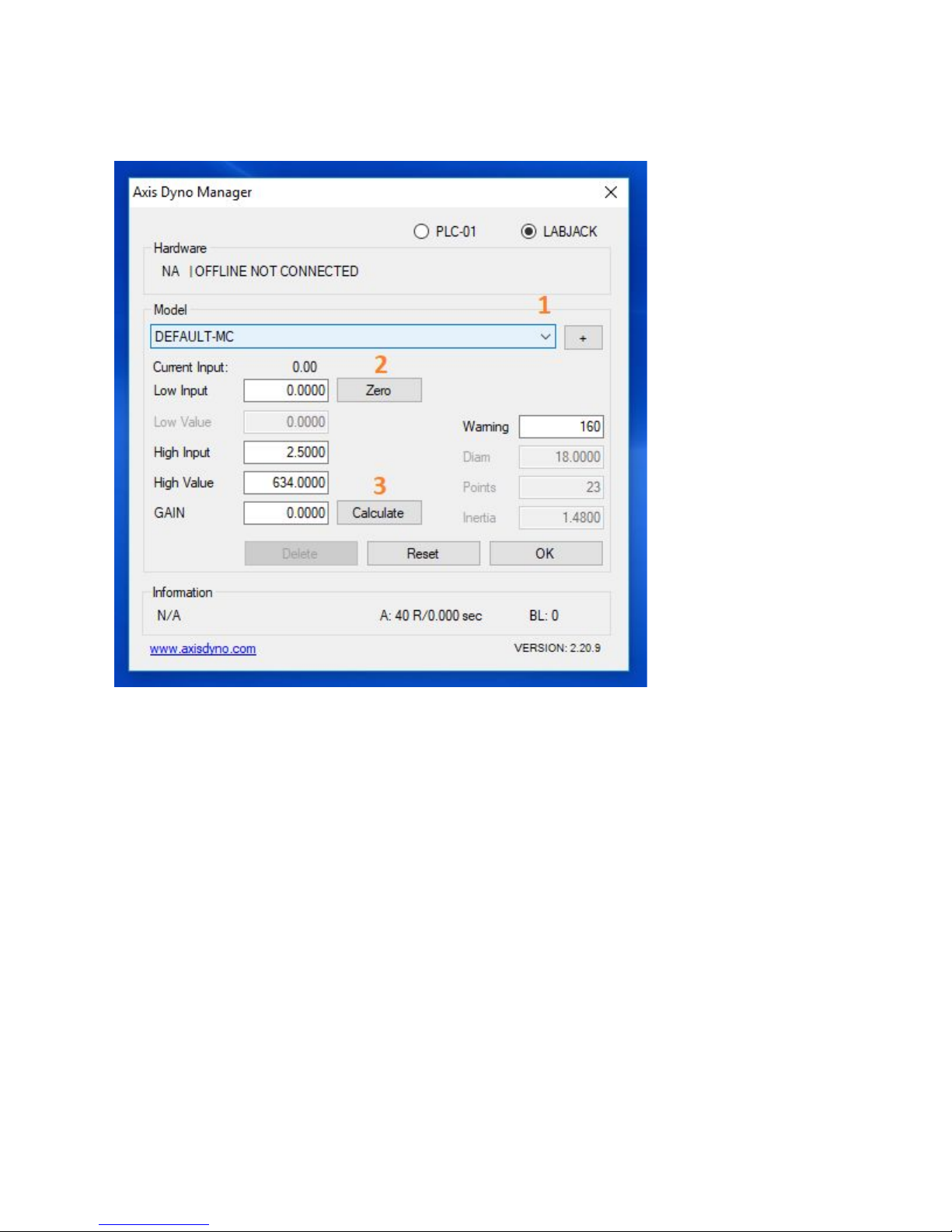
Dyno Manager Calibration Input
Follow these steps to set your Dyno Manager calibration figures:
1. In the drop down menu, select which dyno you are using. “Default-MC” for motorcycle,
“Default-UTV” for UTV, and “Default-TRI” for trike.
2. Enter your low input, “vLi,” in the blue box.
3. Enter your high input, “vHi,” in the orange box.
4. Enter your high value, “vHv,” in the green box.
5. Click “Calculate.” The value in the “Gain” box will change.
6. Calibration numbers are now set.
Note: Each dyno has the Low Input and High Value values determined at the factory. Please
contact your sales representative for these values.
39
Page 40

3.c.4 - Dos and Don'ts of Calculated RPM
3.c.5 - Split Screen Commands & Dual Displays
40
Page 41

Installing & Updating LabJack Drivers
1. Open a web browser and navigate to labjack.com
2. Click the “Support” tab along the top
3. Under the header “Software & Driver” select “Installation Package Downloads.”
4. Under the header “U3, U6, and UE9 Installation Packages” click and expand the
“Downloads” tab.
5. In the expanded view, click the link under the “Beta” header to download the driver.
6. If you already have a version of the Labjack driver installed, you will be asked to remove
the old version; click “OK.”
7. Skip to step 10 if this is a first time install.
8. Click “Uninstall” in the new window.
9. Once the old version has completed uninstalling click “Close.”
10. To start the installation, click “Next” on the Labjack Setup Wizard window.
11. At this point you may select which extra Labjack applications will install. It is recommend
to keep these default settings, then click “Next”
12. Choose a directory to install the Labjack driver and applications. The default directory is
in the “Program Files” Folder. Once done click “Next.”
13. On the next window you may create shortcuts to the labjack applications. Click “Install”
when you are complete.
14. During the installation you may be required to click “Next” several times.
When the installation is complete, click “Finish” on the final screen.
15. Labjack driver is now installed.
Firefox Users:
A. When prompted click “Save File.”
B. Click the blue arrow in the top right corner, then select the Labjack Driver.
C. Select “Run” when prompted.
Chrome Users:
A. Once the download is complete, click the file on the download tab along the bottom of
the window.
B. When prompted, select “Run.”
Explorer Users:
A. Click “Run” on the tab along the bottom.
41
Page 42

Troubleshooting
These are 2 steps to fix the Axis Manager from disappearing in Windows 10
How to set file permission in windows 10.
1. Right Click on the Axis Manager Shortcut
2. Click on properties and go to security tab, check whether any permission have
been set.
3. Once the security tab opens click on “edit”
4. Then click on the user in the list of user names and then in the window below
make sure “Full Control is checked”
How to run a program as the “Administrator” on Windows 10:
1. Right click on the axis icon Then click on properties.
2. Once the windows opens click on the “Compatibility Tab”.
3. On the next window click on “Change settings for all users”
4. Make sure the following has a check mark in the windows.
5. Once this is check click “Apply”
42
Page 43

General Troubleshooting Guide
Step 1: LED Check
A. Remove the top panel/cover of the dyno to the left of the drum when viewed from
behind.
B. With the cover off, power on the dyno.
C. Locate the red chassis board (the red board mounted to the chassis, NOT the drum).
D. On the red board there are 3 LED’s
a. Green LED: This LED should always be on while there is power coming to the
chassis board.
b. Blue LED: This LED will flash while the drum is rotating at a frequency
determined by the speed of the drum
c. Red LED: This LED blinks (~50Hz) to indicate communication with the drum
board. If this light is solid or not on it means the chassis board is not
communicating with the drum board and torque is not being read from the load
cell. If this is the case, skip to Step 4.
Step 2: Load Cell Wires
A. Open up the software and navigate to the “technical” tab which displays the raw labjack
inputs.
B. Locate the red drum board on the side of the drum.
C. While watching the input voltage of AIN06 wiggle each of the wires going into the green
terminal block on the drum board. (See picture) If the voltage jumps at all while agitating
any of the wires, try to narrow down which wire it is and examine for loose connections
or broken wires.
Step 3: Load Cell Check
A. Check the Wheatstone Bridge
a. Set your multimeter to ohms (Ω). If your meter does not auto scale, set it to the
just
high enough to read 350 Ω. This will likely be the 2k or 2000 setting.
b. Referring to the picture above, place one of the probes on terminal 1 (red wire).
c. Place the second probe on terminal 2, 4, and 5 recording the resistance at each
terminal. The resistances should match the table below.
Terminals
Resistance
1 > 2
~ 280 Ω
1 > 4
~ 280 Ω
43
Page 44

1 > 5
~ 350 Ω
Step 3: Load Cell Check - cont.
B. Check Excitation Voltage
a. Set your multimeter to measure up to 5V. This is commonly the 20V setting.
b. Place the black probe on terminal 3 (bare wire).
c. Place the red probe on terminal 2 (black wire). The meter should read between
-5.1V and -4.9V.
d. Place the red probe on terminal 4. The meter should read between 4.95V and
5V.
C. Check Static Output
a. Set your multimeter to the millivolt (mV) setting.
b. Check and record the voltage between terminals 1 and 5. A good load cell will
read
very close to 00.0mV at rest with no vehicle loaded.
D. Check Dynamic Output
a. Set your multimeter to millivolt (mV) as with the last test.
b. Place the multimeter pins on terminals 1 and 5 again.
c. Have another person rock the drum back and forth a couple inches (careful not to
pinch fingers) each way while you watch the multimeter display.
d. Record the high and low numbers seen while rocking the drum.
e. Depending on the force applied in rocking, the readout should be ~±.3mV.
Step 4: Grey Cable Check
A. Locate the Grey Cable connecting the red drum board to the black drum coil board. (see
picture below)
B. While watching the input voltage on AIN06, wiggle the wires at each end of the
connector. In addition to watching the voltage on AIN06, also look to see if wiggling the
wires have any effect on the red LED.
C. Unplug the grey cable from each connector and using a multimeter check for continuity
through each wire. To do this set your multimeter to ohms and place one probe on either
end of the wire in question. A good wire will read within a few ohms of 0.
D. With the grey cable still unplugged check to see that each end is pinned the same.
When viewed from behind with the tab up and order should be red-white-black.
E. Plug the grey cable back into each board.
F. If the grey cable checks out proceed to step 5.
44
Page 45

Step 5: Air Gap Check
A. Loosen the set screw on the plastic collar holding the drum coil board on. (See picture
below)
B. Move the collar and drum board towards the other black board so the two black boards
are in contact.
C. Check to see If the red LED is blinking now. If it is, back the collar far enough so the
black boards are no longer touching but the red LED is still blinking and tighten the set
screw.
D. If the red LED still is not blinking, place collar back in original location and tighten set
screw.
45
Page 46

RPM Troubleshooting Guide
1. First check to make sure that RPM is the only reading not present. If other readings are
also not present then a bigger issue is likely present causing the loss of RPM. If only
RPM is not present, continue on to step 2.
2. Check that the ground cable is connected between the electronics box and the vehicle.
In order to read RPM, the box needs a common ground with the vehicle. Once
connected check again for RPM. box as well as the USB which provides the 5V power.
Wait 30 seconds then reconnect the USB and DC power, order is not important. Check
again for RPM.
3. If the injector harness used has two connectors to mate with the RPM harness, try
4. Power cycle the entire system by unplugging both the DC power to the electronics
swapping them. One of the connectors will have the injector signal while the other will
have a steady ~12V. Applying the 12V to the RPM input will not damage anything;
however you will not have an RPM reading with this configuration. After swapping check
again for RPM.
5. Check for continuity in the injector harness as well as the RPM harness with a
multimeter.
a. If no continuity is present, narrow it down to which harness has the open circuit
and contact Dobeck Performance for a replacement.
b. If both harnesses have continuity, move on to the next step.
6. Disassemble electronics box to expose the internals. Depending on the generation of
box in question the procedure to accomplish this will vary.
7. Make sure that the white/yellow wire is going into the terminal labeled FIO4 on the
labjack.
a. If the wire is going into wrong terminal, swap wires to match the picture below.
Check for RPM.
8. Measure the resistance between FIO4 and VS on the labjack. There should be ~1k
between the two.
a. If resistance reading varies beyond 10 ohms, contact Dobeck Performance.
9. With vehicle hooked up and running, probe the yellow wire inside the electronics box.
Work the throttle to increase RPM’s and look for a corresponding decrease in voltage on
the yellow line.
a. Repeat previous step on while probing the white/yellow wire. If decrease in
voltage with rising RPM is seen only on the yellow wire, then the RPM smoothing
box is bad; contact Dobeck Performance for replacement.
46
Page 47

4.a.3 - Drum Board Voltage Rail Check & Air Gap Adjustment
1. Remove dyno panel to expose the drum board, which is mounted on the side of the
drum. On most models this is on the back left side of the dyno (while looking from
behind).
2. Set multimeter to the highest precision DC voltage readout while still being able to read
5V (generally a 20V setting).
3. Place black/common probe on the center terminal (labeled A in the picture above) of the
green 5 position terminal block located on the drum board.
4. Place red probe on the terminal adjacent to the common terminal, labeled B in the
picture above. Reading should be between -4.95V to -5V.
5. Place red probe on the other terminal adjacent to the common terminal, labeled C in the
picture above. Reading should be between 4.95V and 5V.
6. If either of these readings falls out of the acceptable range check the distance of the air
gap between the transformer boards.
a. Loosen the set screw on the collar holding the circular transformer board.
b. Adjust the air gap spacing while checking the two readings to bring them into
range.
c. Make sure the transformer boards are not so close that they may rub with
vibration or flexing.
d. If adjusting the air gap space has no effect on the voltage readings and they are
still out of range, contact technical support at Dobeck Performance.
47
Page 48

48
 Loading...