

Page 1
USER’S GUIDE
AXIS T93E05 Protective Housing
ENGLISH DEUTSCH
FRAN
Ç
AIS
ITALIANO
ESPAÑOL
Page 2

Legal Considerations
Video and audio surveillance can be prohibited by laws
that vary from country to country. Check the laws in
your local region before using this product for
surveillance purposes.
Trademark Acknowledgments
Apple, Boa, Bonjour, Ethernet, Internet Explorer, Linux,
Microsoft, Mozilla, Netscape Navigator, OS/2, Real,
SMPTE, QuickTime, UNIX, Windows, WWW are
registered trademarks of the respective holders. Java
and all Java-based trademarks and logos are trademarks
or registered trademarks of Sun Microsystems, Inc. in
the United States and other countries. Axis
Communications AB is independent of Sun
Microsystems Inc. UPnP™ is a certification mark of the
UPnP™ Implementers Corporation.
Electromagnetic Compatibility (EMC)
This equipment generates, uses and can radiate radio
frequency energy and, if not installed and used in
accordance with the instructions, may cause harmful
interference to radio communications. However, there is
no guarantee that interference will not occur in a
particular installation.
If this equipment does cause harmful interference to
radio or television reception, which can be determined
by turning the equipment off and on, the user is
encouraged to try to correct the interference by one or
more of the following measures: Re-orient or relocate
the receiving antenna. Increase the separation between
the equipment and receiver. Connect the equipment to
an outlet on a different circuit to the receiver. Consult
your dealer or an experienced radio/TV technician for
help. Shielded (STP) network cables must be used with
this unit to ensure compliance with EMC standards.
USA - This equipment has been tested and found to
comply with the limits for a Class B computing device
pursuant to Subpart B of Part 15 of FCC rules, which are
designed to provide reasonable protection against such
interference when operated in a commercial
environment. Operation of this equipment in a
residential area is likely to cause interference, in which
case the user at his/her own expense will be required to
take whatever measures may be required to correct the
interference.
Canada - This Class B digital apparatus complies with
Canadian ICES-003.
Europe - This digital equipment fulfills the
requirements for RF emission according to limit B of
EN 55022. This product fulfills the requirements for
immunity according to EN 61000-6-1 residential,
commercial and light-industry environments and
EN 55024.
Japan - This is a class B product based on the standard
of the Voluntary Control Council for Interference from
Information Technology Equipment (VCCI). If this is used
near a radio or television receiver in a domestic
environment, it may cause radio interference. Install and
use the equipment according to the instruction manual.
Australia - This electronic device meets the
requirements of the Radio communications
(Electromagnetic Compatibility) Standard AS/NZS
CISPR22:2002.
Korea - As an electromagnetic wave equipment
for office use (Class A), this equipment is
intended to use in other than home area. Sellers
or users need to take note of this.
Safety
Complies to EN 60950-22 (IEC 60950-22), Safety of
Information Technology Equipment.
Equipment Modifications
This equipment must be installed and used in strict
accordance with the instructions given in the user
documentation. This equipment contains no
user-serviceable components. Unauthorized equipment
changes or modifications will invalidate all applicable
regulatory certifications and approvals.
Liability
Every care has been taken in the preparation of this
document. Please inform your local Axis office of any
inaccuracies or omissions. Axis Communications AB
cannot be held responsible for any technical or
typographical errors and reserves the right to make
changes to the product and documentation without
prior notice. Axis Communications AB makes no
warranty of any kind with regard to the material
contained within this document, including, but not
limited to, the implied warranties of merchantability
and fitness for a particular purpose. Axis
Communications AB shall not be liable nor responsible
for incidental or consequential damages in connection
with the furnishing, performance or use of this material.
This product is only to be used for its intended purpose.
RoHS
This product complies with both the European
RoHS directive, 2002/95/EC, and the Chinese
RoHS regulations, ACPEIP.
WEEE Directive
The European Union has enacted a Directive
2002/96/EC on Waste Electrical and Electronic
Equipment (WEEE Directive). This directive is
applicable in the European Union member
states. The WEEE marking on this product (see right) or
its documentation indicates that the product must not
be disposed of together with household waste. To
prevent possible harm to human health and/or the
environment, the product must be disposed of in an
approved and environmentally safe recycling process.
For further information on how to dispose of this
product correctly, contact the product supplier, or the
local authority responsible for waste disposal in your
area. Business users should contact the product supplier
for information on how to dispose of this product
correctly. This product should not be mixed with other
commercial waste.
Support
Should you require any technical assistance, please
contact your Axis reseller. If your questions cannot be
answered immediately, your reseller will forward your
queries through the appropriate channels to ensure a
rapid response. If you are connected to the Internet, you
can:
• download user documentation and firmware updates
• find answers to resolved problems in the FAQ database.
Search by product, category, or phrases
• report problems to Axis support by logging in to your
private support area
Page 3

Safeguards
Please read through this User’s Guide carefully before installing the product. Keep the User’s Guide for further
reference.
CAUTION!
• When transporting the Axis product, use the original packaging or equivalent to prevent damage to the
product.
• Store the Axis product in a dry and ventilated environment.
• Avoid exposing the Axis product to vibration, shocks or heavy pressure and do not install the camera on
unstable brackets, unstable or vibrating surfaces or walls, since this could cause damage to the product.
• Only use handtools when installing the Axis product, the use of electrical tools or excessive force could
cause damage to the product.
• Do not use chemicals, caustic agents, or aerosol cleaners. Use a damp cloth for cleaning.
• Use only accessories that comply with technical specification of the product. These can be provided by Axis
or a third party.
• Do not attempt to repair the product by yourself, contact Axis or your Axis reseller for service matters.
IMPORTANT!
• This Axis product must be used in compliance with local laws and regulations.
ENGLISH
Page 4

Page 5
AXIS T93E05 User’s Guide Page 5
AXIS T93E05 User’s Guide
This User’s Guide provides instructions for installing AXIS T93E05 Protective Housing and
corresponding Axis outdoor cameras, see www.axis.com for information on compatible products.
To install the camera on the network, please see the Installation Guide provided with the camera.
For other details about the camera, see the User’s Manual, available from the CD provided with the
camera, or from www.axis.com.
Installation steps
1. Check the package contents against the list below.
2. Hardware overview. See page 6.
3. Install the hardware. See page 7.
Package contents
Item Models/variants/notes
Housing AXIS T93E05
Wall bracket Wall bracket with internal cable channel
Tools Torx T20 screw driver
Allen key
Other Desiccant Bag
Printed materials AXIS T93E05 User’s Guide (this document)
Drill template
Axis Warranty Document
Optional accessories AXIS T8412 Installation Display
VT Mounting accessories
See www.axis.com for information on compatible products, accessories,
product documentation, installation tools and other software.
ENGLISH
Page 6
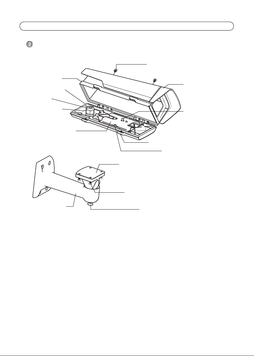
Page 6 AXIS T93E05 User’s Guide
Sunshield adjustment screw and
washer (2x)
Bottom cover screw (2x)
Bracket adjustment screw
Cable gland
Gasket
Holder screw (2x)
Camera screw
Sunshield
Top cover
Holder
Wall bracket
Rubber seal
Bracket screw (4x)
Wall bracket
Housing
Bottom cover
Hardware overview
Page 7

AXIS T93E05 User’s Guide Page 7
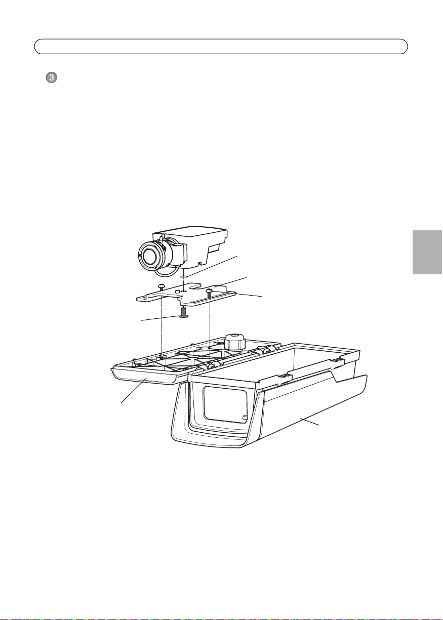
Example image: AXIS M1114 Network camera and AXIS T93E05 Protective Housing
Holder screw (2x)
Camera screw
(remove o-ring)
Holder
O-ring (discard)
Bottom cover
Top cover
Install the hardware
Install the camera in the housing
The instructions below describe how to install an indoor camera in AXIS T93E05 Protective Housing.
For instructions on how to install a corresponding outdoor camera, refer to Install the wall bracket,
on page 8.
1. Loosen the bottom cover screws and open the top cover, see illustration on page 6.
2. Loosen the holder screw and remove the holder. Discard the o-ring.
3. Secure the camera and holder with the screw according to the illustration below. Tighten the
camera screw to 2 Nm. Be careful not to overtighten the screw.
ENGLISH
4. Fit the holder on the bottom cover and adjust its position. Allow just enough distance,
approximately 5–10 mm (0.2–0.4 in.), between the camera lens and the front end of the
housing to fit the top cover without the window scratching the lens.
5. Tighten the screws.
Page 8

Page 8 AXIS T93E05 User’s Guide
Example image: AXIS M1114 Network camera and AXIS T93E05 Protective Housing
Network cable (route through wall bracket)
Bracket screw (4x)
Bracket adjustment screw
Wall bracket
Gasket
Rubber seal
Cable gland nut
Install the wall bracket
1. Use the supplied drill template to prepare a wall or pole for installation of the wall bracket.
2. Route a shielded network cable through the wall bracket. Leave approximately 12 cm (4.7”) of
cable for connecting the camera.
3. Install the wall bracket on a wall or pole and make sure that the screws and plugs are
appropriate for the material (e.g. wood, metal, sheet rock, stone).
Install the camera on the bracket
Axis outdoor cameras
1. Loosen the bottom cover screws and open the top cover, see illustration on page 6.
2. Refer to the instructions in Axis indoor cameras installed in AXIS T93E05.
Axis indoor cameras installed in AXIS T93E05
1. Unscrew the cable gland nut and remove the gasket from the cable gland.
2. Route the shielded network cable through the cable gland.
Note: Always use a shielded network cable (STP) intended for outdoor use between the camera and
the end point and ensure that the end point is properly grounded. Installations of Axis
cameras using a shielded network cable (STP) and a properly grounded end point have been
tested to comply with industry immunity standards’ levels such as surge protection. Any other
installation method will void the warranty and leave the unit at a risk.
3. Install the camera with the housing on the bracket and tighten the bracket screws.
4. Attach the gasket to the network cable and push the gasket back into the gland.
Page 9

AXIS T93E05 User’s Guide Page 9
Desiccant bag
Example image: AXIS M1114 Network camera and AXIS T93E05 Protective Housing
Sunshield adjustment
Bottom cover screw (2x)
screw and washer (2x)
5. Tighten the cable gland nut.
6. Connect the camera to the network.
7. Loosen the bracket adjustment screw to aim the camera to the point of interest and focus the
camera using an installation display, available as an optional accessory from Axis, or according
to the instructions in the Installation Guide provided with the camera.
8. Remove the plastic wrapper from the desiccant bag and put the desiccant bag in the hollow
space around the cable gland.
Note: The desiccant bag should be replaced regularly. Always replace the desiccant bag after the
housing has been opened.
9. Close the top cover and tighten the bottom cover screws.
CAUTION!
Risk of pinching
Be aware of the hinge space between the top and bottom covers. Never put your fingers between
the hinges while closing the top cover.
ENGLISH
10. Loosen the sunshield adjustment screws and adjust the sunshield to the desired position.
Page 10

Page 10 AXIS T93E05 User’s Guide
Further information
See the Installation Guide provided with the camera for information on how to assign an IP address,
set the password and access the video stream. The Installation Guide is also available from the Axis
Web site at www.axis.com
Technical Specifications
Function/group Item Specification
Model AXIS T93E05
General Casing ASA Polymer
Color: white NCS S 1002-B
Operating conditions -20°C to 50°C (-4°F to122°F)*
Storage temperature -20°C to 50°C (-4°F to122°F)
Approvals IEC 60068-2-6, IEC 60068-2-27, EN 60950-22, IEC 60529
Dimensions (HxWxD) 95 x 126 x 304 mm (3.8” x 5” x 12”)
Weight
Included accessories Wall bracket
Humidity 15 – 100% (condensing)
* Operating temperatures may vary depending on camera, see the User’s
Manual, available from the CD provided with the camera, or from
www.axis.com
IP66
580 g (1.28 lb.)
Sunshield
Page 11

Page 12

Mesures de sécurité
Lisez attentivement le présent guide d’utilisation avant d’installer le produit. Conservez le guide d’utilisation
pour référence ultérieure.
ATTENTION !
• Pour éviter d’endommager le produit Axis, utilisez l’emballage d’origine ou un équivalent pour le
transporter.
• Stockez le produit Axis dans un environnement sec et aéré.
• Évitez d’exposer le produit Axis à des vibrations, des chocs ou une trop forte pression et ne l’installez pas
sur des supports instables ou sur des surfaces ou des murs instables ou vibrants. Cela risque de
l’endommager.
• Utilisez uniquement des outils à main pour installer le produit Axis : l’utilisation d’outils électriques ou
l’usage excessif de la force risquent de l’endommager.
• N’utilisez ni produits chimiques, ni substances caustiques ou nettoyeurs aérosol. Utilisez un chiffon humide
pour le nettoyage.
• N’utilisez que des accessoires conformes aux caractéristiques techniques du produit. Ceux-ci peuvent être
fournis par Axis ou un fournisseur tiers.
• Ne tentez pas de réparer le produit vous-même, contactez Axis ou votre revendeur Axis pour toute
réparation.
IMPORTANT !
• Ce produit Axis doit être utilisé conformément aux lois et réglementations locales en vigueur.
Page 13
AXIS T93E05 Guide d’utilisation Page13
AXIS T93E05 Guide d’utilisation
Ce guide d’utilisation fournit les instructions d’installation du AXIS T93E05 Caisson de protection et
des caméras extérieures Axis correspondantes ; consultez le site www.axis.com pour plus
d’informations sur les produits compatibles.
Pour installer la caméra sur le réseau, consultez le guide d’installation fourni avec la caméra. Pour
en savoir plus sur la caméra, consultez le manuel de l’utilisateur, disponible sur le CD fourni avec la
caméra ou sur le site www.axis.com.
Procédure d’installation
1. Vérifiez le contenu de l’emballage par rapport à la liste ci-dessous.
2. Vue d’ensemble du matériel. Reportez-vous à la page 14.
3. Installation du matériel. Reportez-vous à la page 15.
Contenu de l’emballage
Élément Modèles/variantes/remarques
Caisson AXIS T93E05
Support mural Support mural avec chemin de câble interne
Outils Tournevis Torx T20
Clé hexagonale
Autre Sachet dessiccatif
Documentation imprimée AXIS T93E05 Guide d’utilisation (le présent document)
Gabarit de perçage
Document de garantie Axis
FRAN
Ç
AIS
Accessoires en option Moniteur d’installation AXIS T8412
Accessoires de fixation VT
Consultez le site www.axis.com pour plus d’informations sur les produits
compatibles, les accessoires, la documentation, les outils d’installation et les
autres logiciels.
Page 14

Page 14 AXIS T93E05 Guide d’utilisation
Vis de réglage et rondelle
du pare-soleil (x2)
Vis du couvercle inférieur (x2)
Vis de réglage du support mural
Presse-étoupe
Joint
Vis du support (x2)
Vis de la caméra
Pare-soleil
Couvercle supérieur
Support
Support mural
Joint en caoutchouc
Vis du support mural (x4)
Support mural
Caisson
Couvercle inférieur
Vue d’ensemble du matériel
Page 15
AXIS T93E05 Guide d’utilisation Page15
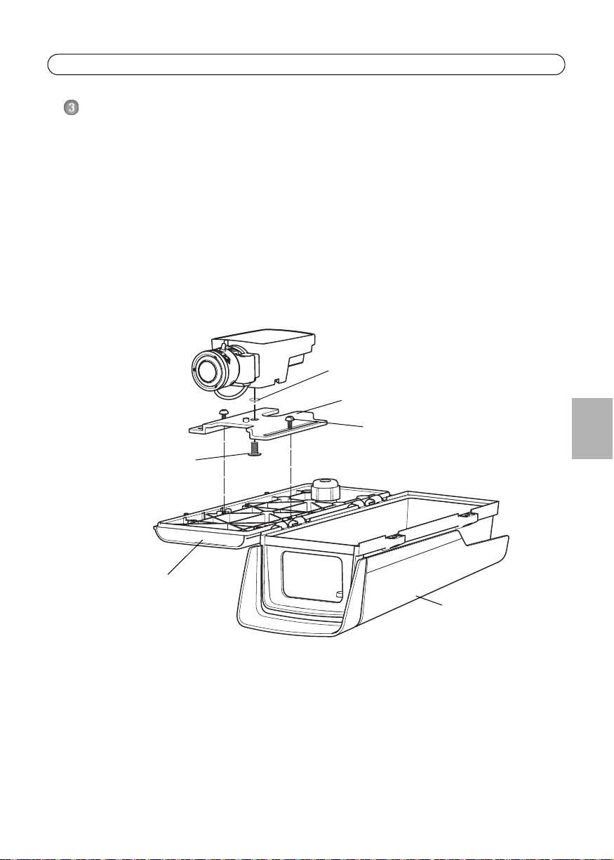
Illustration : Caméra réseau AXIS M1114 et Caisson de protection AXIS T93E05
Vis du support (x2)
Vis de la caméra
(déposer joint torique)
Support
Joint torique (rebut)
Couvercle inférieur
Couvercle supérieur
Installation du matériel
Installation de la caméra dans le caisson
Les instructions ci-dessous décrivent la procédure d’installation d’une caméra intérieure dans le
caisson de protection AXIS T93E05. Pour des instructions d’installation concernant une caméra
extérieure correspondante, consultez Installation du support mural, sur page 16.
1. Desserrez les vis du couvercle inférieur et ouvrez le couvercle supérieur, voir l’illustration à la
page 14.
2. Desserrez les vis du support pour pouvoir le retirer. Déposez le joint torique.
3. Stabilisez la caméra et le support avec la vis comme montré sur l’illustration ci-dessous. Serrez
la vis de la caméra à 2 Nm. Veillez à ne pas trop la serrer.
FRAN
Ç
AIS
4. Positionnez le support sur le couvercle inférieur et ajustez sa position. Prévoyez une distance
suffisante, d’environ 5 à 10 mm, entre l’objectif de la caméra et l’extrémité avant du boîtier
pour positionner le couvercle supérieur sans que la fenêtre ne raye l’objectif.
5. Serrez les vis.
Page 16

Page 16 AXIS T93E05 Guide d’utilisation
Installation du support mural
1. Préparez le mur ou le poteau de montage sur lequel le support mural doit être installé à l’aide
du gabarit de perçage fourni.
2. Acheminez un câble réseau blindé à travers le support mural. Laissez environ 12 cm de câble
pour la connexion de la caméra.
3. Fixez le support mural sur un mur ou un poteau et assurez-vous que les vis et les fiches sont
adaptées au matériau (p. ex., bois, métal, plaque de plâtre ou pierre).
Installation de la caméra sur le support mural
Caméras extérieures Axis
1. Desserrez les vis du couvercle inférieur et ouvrez le couvercle supérieur, voir l’illustration à la
page 14.
2. Reportez-vous aux instructions de la section Caméras intérieures Axis installées dans AXIS
T93E05.
Caméras intérieures Axis installées dans AXIS T93E05
1. Dévissez l’écrou du presse-étoupe et déposez le joint du presse-étoupe.
2. Acheminez le câble réseau blindé à travers le presse-étoupe.
Remarque :Utilisez toujours un câble réseau à paires torsadées blindé prévu pour une utilisation à
l’extérieur afin de relier la caméra et le point terminal. Assurez-vous également que le point
terminal est correctement mis à la terre. Les installations des caméras Axis à l’aide d’un câble
réseau à paires torsadées blindé et d’un point terminal correctement mis à la terre ont été
contrôlées conformes aux niveaux de la norme relative à l’immunité de l’industrie, comme la
protection contre les surtensions. Toute autre méthode d’installation annule la garantie et
expose le produit à des risques.
3. Installez la caméra avec le caisson sur le support mural et serrez les vis du support.
Page 17

AXIS T93E05 Guide d’utilisation Page17
Illustration : Caméra réseau AXIS M1114 et Caisson de protection AXIS T93E05
Câble réseau (chemin à travers le support mural)
Vis du support mural (x4)
Vis de réglage du support mural
Support mural
Joint
Joint en
Écrou du
presse-étoupe
caoutchouc
Sachet dessiccatif
Illustration : Caméra réseau AXIS M1114 et Caisson de protection AXIS T93E05
4. Fixez le joint sur le câble réseau et repassez-le dans le presse-étoupe.
5. Serrez l’écrou du presse-étoupe.
6. Connectez la caméra au réseau.
7. Desserrez la vis de réglage du support mural afin d’orienter la caméra dans la direction voulue
et effectuez la mise au point de la caméra à l’aide du moniteur d’installation, disponible en tant
qu’accessoire en option auprès d’Axis, ou conformément aux instructions décrites dans le guide
d’installation fourni avec la caméra.
8. Retirez l’emballage plastique du sachet dessiccatif et placez le sachet dessiccatif dans l’espace
creux autour du presse-étoupe.
FRAN
Ç
AIS
Page 18

Page 18 AXIS T93E05 Guide d’utilisation
Vis de réglage et rondelle
Vis du couvercle inférieur (x2)
du pare-soleil (x2)
Remarque : Le sachet dessiccatif doit être remplacé régulièrement. Remplacez toujours le sachet
dessiccatif après avoir ouvert le caisson.
9. Fermez le couvercle supérieur et serrez les vis du couvercle inférieur.
ATTENTION !
Risque de pincement
Attention à la charnière séparant les couvercles supérieur et inférieur. Ne mettez jamais vos doigts
entre les charnières lorsque vous fermez le couvercle supérieur.
10. Desserrez les vis de réglage du pare-soleil pour pouvoir l’ajuster et le mettre dans la position
souhaitée.
Page 19
AXIS T93E05 Guide d’utilisation Page19
Informations complémentaires
Consultez le guide d’installation fourni avec la caméra pour plus d’informations sur l’attribution
d’une adresse IP, la configuration d’un mot de passe et l’accès au flux de données vidéo. Le guide
d’installation est également disponible sur le site Web d’Axis à l’adresse www.axis.com.
Caractéristiques techniques
Fonction/
groupe
Général Caisson Polymère ASA
Élément Caractéristiques techniques
Modèle AXIS T93E05
Couleur : blanc NCS S 1002-B
Conditions d’utilisation -20 °C à 50 °C *
Humidité 15 - 100 % (condensation)
* Les températures de fonctionnement peuvent varier d’une caméra à
l’autre, consultez le manuel de l’utilisateur, disponible sur le CD fourni
avec la caméra ou sur le site www.axis.com.
Température de
stockage
Homologations IEC 60068-2-6, IEC 60068-2-27, EN 60950-22, IEC 60529
Dimensions (H x L x P) 95 x 126 x 304 mm
Poids
Accessoires fournis Support mural
- 20 °C à 50 °C
IP66
580 g
Pare-soleil
FRAN
Ç
AIS
Page 20

Sicherheitsvorkehrungen
Bitte lesen Sie zunächst dieses Benutzerhandbuch vollständig durch, bevor Sie mit der Installation Ihres
Produkts beginnen. Halten Sie das Benutzerhandbuch bereit, falls Sie darauf zurückgreifen müssen.
VORSICHT!
• Transportieren Sie das Axis-Produkt nur in der Originalverpackung bzw. in einer vergleichbaren Verpackung,
damit das Produkt nicht beschädigt wird.
• Lagern Sie das Axis-Produkt in einer trockenen und belüfteten Umgebung.
• Achten Sie darauf, dass das Axis-Produkt keinen Erschütterungen, Stößen oder starkem Druck ausgesetzt ist
und montieren Sie die Kamera nicht auf instabilen Halterungen oder auf instabilen und vibrierenden
Oberflächen oder Wänden. Dies könnte zu Beschädigungen des Produkts führen.
• Verwenden Sie keine elektrischen Werkzeuge zur Montage des Axis-Produkts, da diese das Produkt
beschädigen könnten.
• Verwenden Sie keine chemischen, ätzenden oder Aerosol-Reinigungsmittel. Verwenden Sie zur Reinigung
ein feuchtes Tuch.
• Verwenden Sie nur Zubehör, das den technischen Spezifikationen des Produkts entspricht. Dieses ist von
Axis oder Drittanbietern erhältlich.
• Versuchen Sie nicht, das Produkt selbst zu reparieren. Wenden Sie sich bei Service-Angelegenheiten an Axis
oder an Ihren Axis-Händler.
WICHTIG!
• Verwenden Sie dieses Axis-Produkt unter Beachtung der geltenden rechtlichen Bestimmungen.
Page 21

AXIS T93E05 Bedienungsanleitung Seite 21
AXIS T93E05 Bedienungsanleitung
Dieses Bedienungsanleitung enthält Anweisungen zur Installation des AXIS T93E05 Schutzgehäuses
und der entsprechenden Außenbereichskameras. Informationen zu geeigneten Kameramodellen
finden Sie unter „www.axis.com“.
Anweisungen zur Installation der Kamera im Netzwerk finden Sie in der Installationsanleitung zu
Ihrer Kamera. Weitere Angaben zur Kamera finden Sie im Benutzerhandbuch, das auf der CD, die im
Lieferumfang der Kamera enthalten ist, sowie auf unserer Website unter „www.axis.com“ zur
Verfügung steht.
Installationsschritte
1. Prüfen Sie, ob alle in der nachfolgenden Liste aufgeführten Komponenten vorhanden sind.
2. Sehen Sie sich die Hardwareübersicht an. Siehe Seite 22.
3. Installieren Sie die Hardware. Siehe Seite 23.
Inhalt des Produktpakets
Komponente Modelle/Varianten/Anmerkungen
Gehäuse AXIS T93E05
Wandhalterung Wandhalterung mit internem Kabelschacht
Tools Torx T20-Schraubendreher
Inbusschlüssel
Sonstiges Antikondensationsbeutel
Gedruckte Dokumente AXIS T93E05 Bedienungsanleitung (dieses Dokument)
Bohrschablone
Axis-Garantieerklärung
Optionales Zubehör AXIS T8412 Installationsmonitor
VT Montagezubehör
Weitere Informationen zur Produktdokumentation sowie zu kompatiblen
Produkten, Zubehör, Installationswerkzeugen und anderer Software finden Sie
unter „www.axis.com“.
DEUTSCH
Page 22

Seite 22 AXIS T93E05 Benutzerhandbuch
Einstellschrauben für Sonnenschutz
undDichtungsring (2)
Schraube für untere Abdeckung (2)
Einstellschraube für Halterung
Kabelverschraubung
Dichtung
Schraube für Halter (2)
Schraube für Kamera
Sonnenschutz
Obere Abdeckung
Halterung
Wandhalterung
Gummidichtung
Schraube für Halterung (4)
Wandhalterung
Gehäuse
Untere Abdeckung
Hardwareübersicht
Page 23
AXIS T93E05 Bedienungsanleitung Seite 23
Beispielbild: AXIS M1114 Netzwerk-Kamera und AXIS T93E05 Schutzgehäuse
Schraube für Halter (2)
Schraube für Kamera
(O-Ring entfernen)
Halterung
Entfernter O-Ring
Untere Abdeckung
Obere Abdeckung
Installation der Hardware
Kamera im Gehäuse anbringen
In den folgenden Anweisungen wird beschrieben, wie Sie eine Innenraumkamera im AXIS T93E05
Schutzgehäuse montieren. Anweisungen zur Installation des Außenbereichmodells finden Sie unter
Installation der Wandhalterung, auf Seite 24.
1. Lösen Sie die Schrauben der unteren Abdeckung und öffnen Sie die obere Abdeckung. Siehe
Abbildung auf Seite 22.
2. Lösen Sie die Schraube des Halters und entfernen Sie den Halter. Nehmen Sie den O-Ring ab.
3. Sichern Sie die Kamera und den Halter mit der Schraube, wie in der folgenden Abbildung
dargestellt. Ziehen Sie die Kameraschraube fest (Drehmoment 2 Nm). Achten Sie darauf, dass
Sie die Schraube nicht überdrehen.
DEUTSCH
4. Setzen Sie den Halter auf die untere Abdeckung und richten Sie ihn aus. Halten Sie einen
ausreichenden Abstand (etwa 5 bis 10 mm) vom Kameraobjektiv zur Vorderseite des Gehäuses
ein, sodass die obere Abdeckung passt, ohne das Objektiv zu zerkratzen.
5. Ziehen Sie die Schrauben fest.
Page 24

Seite 24 AXIS T93E05 Benutzerhandbuch
Installation der Wandhalterung
1. Bereiten Sie die Befestigung der Wandhalterung an der Wand oder an einem Mast vor und
markieren Sie die Position der Bohrlöcher mithilfe der mitgelieferten Bohrschablone.
2. Führen Sie ein abgeschirmtes Netzwerkkabel durch die Wandhalterung. Sie benötigen noch
etwa 12 cm Kabel für den Anschluss an die Kamera.
3. Montieren Sie die Wandhalterung an einer Wand oder einem Mast. Stellen Sie sicher, dass Sie
für das Material (z. B. Holz, Metall, Gipskarton, Stein) die geeigneten Schrauben und Dübel
verwenden.
Anbringen der Kamera an der Halterung
Kameras von Axis für den Außenbereich
1. Lösen Sie die Schrauben der unteren Abdeckung und öffnen Sie die obere Abdeckung. Siehe
Abbildung auf Seite 22.
2. Befolgen Sie die Anweisungen unter Innenraumkameras von Axis im AXIS T93E05.
Innenraumkameras von Axis im AXIS T93E05
1. Lösen Sie die Kabelverschraubungsmutter und nehmen Sie die Dichtung aus der
Kabelverschraubung.
2. Führen Sie das abgeschirmte Netzwerkkabel durch die Kabelverschraubung.
Hinweis: Verbinden Sie die Kamera immer über ein für den Außenbereich geeignetes abgeschirmtes
Netzwerkkabel mit dem Endpunkt. Stellen Sie sicher, dass der Endpunkt ordnungsgemäß
geerdet ist. Die Verwendung eines abgeschirmten Netzwerkkabels und eines geerdeten
Endpunkts für die Installation von Axis Kameras wurde sorgfältig getestet und erfüllt die
Industrienormen bezüglich Störfestigkeit, z. B. Überspannungsschutz. Wenn Sie andere
Installationsmethoden verwenden, erlischt die Garantie und der sichere Betrieb des Geräts
ist nicht gewährleistet.
3. Montieren Sie die Kamera mit dem Gehäuse an der Halterung und ziehen Sie die
Halterungsschrauben fest.
Page 25

AXIS T93E05 Bedienungsanleitung Seite 25
Beispielbild: AXIS M1114 Netzwerk-Kamera und AXIS T93E05 Schutzgehäuse
Netzwerkkabel (durch Wandhalterung führen)
Schraube für Halterung (4)
Einstellschraube für Halterung
Wandhalterung
Dichtung
Gummi-
Kabelverschraubungsmutter
dichtung
Antikondensationsbeutel
Beispielbild: AXIS M1114 Netzwerk-Kamera und AXIS T93E05 Schutzgehäuse
4. Bringen Sie die Dichtung am Netzwerkkabel an und drücken Sie sie wieder in die
Kabelverschraubung.
5. Ziehen Sie die Kabelverschraubungsmutter fest.
6. Verbinden Sie die Kamera mit dem Netzwerk.
7. Lösen Sie die Einstellschraube der Halterung und richten Sie die Kamera auf das gewünschte
Ziel aus. Führen Sie die Fokussierung der Kamera mithilfe des Installationsmonitors, der als
optionales Zubehör von Axis erhältlich ist, oder gemäß den Anweisungen in der
Installationsanleitung zu Ihrer Kamera durch.
8. Entfernen Sie die Plastikschutzhülle des Antikondensationsbeutels und legen Sie den
Antikondensationsbeutel in den Hohlraum um die Kabelverschraubung.
DEUTSCH
Hinweis:Der Antikondensationsbeutel sollte regelmäßig ausgetauscht werden. Tauschen Sie den
Page 26

Seite 26 AXIS T93E05 Benutzerhandbuch
Einstellschraube für
Schraube für untere Abdeckung (2)
Sonnenschutz und
Dichtungsring (2)
Antikondensationsbeutel immer aus, wenn das Gehäuse geöffnet wurde.
9. Schließen Sie die obere Abdeckung und ziehen Sie die Schrauben der unteren Abdeckung fest.
VORSICHT!
Einklemmgefahr
Beachten Sie die Scharnieraussparung zwischen der oberen und unteren Abdeckung. Fassen Sie
niemals mit den Fingern in diese Aussparung, während Sie die obere Abdeckung schließen.
10. Lösen Sie die Einstellschrauben des Sonnenschutzes und bringen Sie den Sonnenschutz in die
gewünschte Position.
Page 27

AXIS T93E05 Bedienungsanleitung Seite 27
Weitere Informationen
Im Installationshandbuch zu Ihrer Kamera finden Sie Informationen zum Zuweisen einer IP-Adresse
und Festlegen des Kennworts sowie zum Zugriff auf den Videostrom. Das Benutzerhandbuch steht
ebenfalls auf der Website von Axis unter „www.axis.com“ zur Verfügung.
Technische Daten
Funktion/
Gruppe
Allgemein Gehäuse ASA-Polymer
Komponente Spezifikation
Modell AXIS T93E05
Farbe: weiß NCS S 1002-B
Betriebsbedingungen -20°C bis 50°C*
Luftfeuchtigkeit 15 bis 100 % (kondensierend)
* Die Betriebstemperaturen können je nach Kameramodell variieren.
Informationen hierzu finden Sie im Benutzerhandbuch, das auf der CD,
die im Lieferumfang der Kamera enthalten ist, zur Verfügung steht, sowie
auf unserer Website unter „www.axis.com“.
Lagerungstemperatur -20°C bis 50°C
Zulassungen IEC 60068-2-6, IEC 60068-2-27, EN 60950-22, IEC 60529
IP66
Abmessung (H x B x T) 95 x 126 x 304 mm
Gewicht
Im Lieferumfang
enthaltenes Zubehör
580 g
Wandhalterung
Sonnenschutz
DEUTSCH
Page 28

Precauzioni
Leggere per intero e con attenzione questa Guida per l’utente prima di installare il prodotto. Conservare la Guida
per l’utente per ulteriori riferimenti.
ATTENZIONE!
• Quando si trasporta un prodotto Axis, utilizzare l'imballo originale o un imballo equivalente per evitare
danni al prodotto.
• Conservare il prodotto Axis in un ambiente asciutto e ventilato.
• Evitare di esporre il prodotto Axis a vibrazioni, urti o pressioni eccessive e non installare la telecamera su
staffe instabili, superfici o pareti instabili o vibranti, poiché in tal modo si potrebbe danneggiare il prodotto.
• Per l'installazione del prodotto Axis, utilizzare solo attrezzi manuali, l'utilizzo di utensili elettrici o
l'applicazione di una forza eccessiva potrebbero danneggiare il prodotto.
• Non utilizzare sostanze chimiche, agenti caustici o detergenti aerosol. Utilizzare un panno umido per la
pulizia.
• Usare solo accessori compatibili con le specifiche tecniche del prodotto. Questi possono essere forniti da
Axis o da terze parti.
• Non tentare di riparare da soli il prodotto, ma contattare Axis o il rivenditore Axis per qualsiasi argomento
relativo all'assistenza tecnica.
IMPORTANTE!
• Questo prodotto Axis deve essere utilizzato in conformità alle leggi e alle regolamentazioni locali.
Page 29

AXIS T93E05 Guida per l'utente Pagina 29
Guida per l'utente di AXIS T93E05
Questa Guida per l'utente fornisce le istruzioni per l’installazione dell’Alloggiamento di protezione
AXIS T93E05 e delle corrispondenti telecamere per esterni Axis, vedere www.axis.com per
informazioni sui prodotti compatibili.
Per installare la telecamera nella rete, vedere la Guida all'installazione fornita con la telecamera.
Per tutte le altre informazioni relative all'uso della telecamera, consultare la Guida per l'utente,
disponibile sul CD fornito con la telecamera o sul sito www.axis.com.
Procedura di installazione
1. Controllare il contenuto della confezione con l'elenco che segue.
2. Panoramica dell’hardware. Vedere pagina 30.
3. Installazione dell'hardware. Vedere pagina 31.
Contenuto della confezione
Elemento Modelli/varianti/note
Alloggiamento AXIS T93E05
Staffa per il montaggio a
parete
Strumenti Cacciavite Torx T20
Altra Sacchetto di essiccante
Materiali stampati Guida per l'utente di AXIS T93E05 (questo documento)
Staffa per il montaggio a muro con canalina interna per cavi
Chiave Allen
Maschera per la foratura
Documento di garanzia Axis
ITALIANO
Accessori opzionali AXIS T8412 Installation Display
Accessori di montaggio VT
Per informazioni su prodotti compatibili, accessori, documentazione del
prodotto, attrezzi per l'installazione e altro software, visitare il sito web
www.axis.com
Page 30

Pagina 30 AXIS T93E05 Guida per l'utente
Vite di regolazione e rondella
del parasole (2x)
Vite del coperchio inferiore (2x)
Viti di regolazione della staffa
Pressacavo
Guarnizione
Vite del supporto (2x)
Vite della telecamera
Parasole
Copertura superiore
Supporto
Staffa per il montaggio a parete
Guarnizione in gomma
Vite della staffa (4x)
Staffa per il montaggio a parete
Alloggiamento
Copertura inferiore
Panoramica dell’hardware
Page 31

AXIS T93E05 Guida per l'utente Pagina 31
Esempio: Telecamera di rete AXIS M1114 e alloggiamento di protezione AXIS T93E05
Vite del supporto (2x)
Vite della telecamera
(rimuovere l’anello
Supporto
Anello di guarnizione (da scartare)
Copertura inferiore
Copertura superiore
di guarnizione)
Installazione dell'hardware
Installare la telecamera nell'alloggiamento
Le istruzioni che seguono descrivono installare una telecamera per interni nell’Alloggiamento di
protezione AXIS T93E05. Per le istruzioni sull’installazione di una corrispondente telecamera per
esterni, fare riferimento a Installare la staffa di montaggio a parete, a pagina 32.
1. Allentare le viti della copertura inferiore e aprire la copertura superiore, come nell'illustrazione
a pagina 30.
2. Allentare la vite del supporto e rimuoverlo. Gettare l’anello di guarnizione.
3. Fissare la telecamera e il supporto con la vite, come mostrato nell’illustrazione che segue.
Serrare la vite della telecamera a 2 Nm. Fare attenzione a non serrare eccessivamente la vite.
4. Montare il supporto sulla copertura inferiore e regolarne la posizione. Lasciare una distanza
sufficiente, circa 5–10 mm, tra l'obiettivo della telecamera e l'estremità anteriore
dell'alloggiamento, in modo che la copertura superiore possa essere montata senza graffiare
l'obiettivo.
5. Serrare le viti.
ITALIANO
Page 32

Pagina 32 AXIS T93E05 Guida per l'utente
Installare la staffa di montaggio a parete
1. Utilizzare la maschera di foratura fornita per preparare una parete o un'asta per l'installazione
della staffa a parete.
2. Far passare un cavo di rete schermato attraverso la staffa per il montaggio a parete. Lasciare
circa 12 cm di cavo per collegare la telecamera.
3. Installare la staffa a parete su una parete o un'asta e assicurarsi che le viti e i connettori siano
appropriati per il materiale (ad esempio legno, metallo, cartongesso, pietra).
Installare la telecamera sulla staffa
Telecamere Axis per ambienti esterni
1. Allentare le viti della copertura inferiore e aprire la copertura superiore, come nell'illustrazione
a pagina 30.
2. Seguire le istruzioni riportate in Telecamere Axis per interni installate in AXIS T93E05.
Telecamere Axis per interni installate in AXIS T93E05
1. Svitare il dado del pressacavo e rimuovere la guarnizione dal pressacavo.
2. Far passare un cavo di rete schermato attraverso il pressacavo.
Nota: Usare sempre un cavo di rete schermato (STP) per ambienti interni fra la telecamera e il punto
terminale e assicurarsi che il punto terminale sia correttamente connesso a terra. Le
installazioni delle telecamere Axis con un cavo di rete schermato (STP) e un punto terminale
correttamente connesso a terra sono state collaudate in modo da soddisfare i livelli standard
industriali, ad esempio per la protezione dai picchi di tensione. Qualsiasi altro metodo di
installazione rende nulla la garanzia ed espone a rischi l'unità.
3. Installare la telecamera con l’alloggiamento sulla staffa, quindi serrare le viti della staffa.
Page 33

AXIS T93E05 Guida per l'utente Pagina 33
Esempio: Telecamera di rete AXIS M1114 e alloggiamento di protezione AXIS T93E05
Cavo di rete (far passare attraverso la staffa per il montaggio a parete)
Vite della staffa (4x)
Viti di regolazione della staffa
Staffa per il
Guarnizione
Guarnizione
Dado del
pressacavo
in gomma
montaggio a parete
Sacchetto dell’essiccante
Esempio: Telecamera di rete AXIS M1114 e alloggiamento di protezione AXIS T93E05
4. Montare la guarnizione sul cavo di rete e spingere di nuovo la guarnizione nel pressacavo.
5. Serrare il dado del pressacavo.
6. Collegare la telecamera alla rete.
7. Allentare la vite di regolazione della staffa per rivolgere la telecamera verso il punto desiderato
e metterla a fuoco utilizzando un display per l’installazione, disponibile come accessorio
opzionale da Axis, secondo le istruzioni fornite nella Guida all’installazione fornita con la
telecamera.
8. Rimuovere la fascetta in plastica dal sacchetto dell’essiccante e collocare il sacchetto
dell’essiccante nello spazio incavato intorno al pressacavo.
ITALIANO
Nota: Il sacchetto dell’essiccante deve essere sostituito regolarmente. Sostituire sempre il sacchetto
Page 34

Pagina 34 AXIS T93E05 Guida per l'utente
Vite di regolazione e
Vite del coperchio inferiore (2x)
rondella del parasole (2x)
dell’essiccante dopo avere aperto l'alloggiamento.
9. Chiudere la copertura superiore e serrare le viti della copertura inferiore.
ATTENZIONE!
Rischio di schiacciamento
Fare attenzione allo spazio della cerniera tra il coperchio superiore e quello inferiore. Non mettere
mai le dita tra le cerniere durante la chiusura del coperchio superiore.
10. Allentare le viti di regolazione del parasole e regolarlo nella posizione desiderata.
Page 35

AXIS T93E05 Guida per l'utente Pagina 35
Ulteriori informazioni
Vedere la Guida all’installazione fornita con la telecamera per informazioni sul modo per assegnare
l'indirizzo IP, impostare la password a accedere al flusso video. La Guida all’installazione è
disponibile sul sito web di Axis all'indirizzo www.axis.com
Specifiche tecniche
Funzione/
gruppo
Caratteristiche
generali
Elemento Specifica
Modello AXIS T93E05
Involucro Polimero ASA
Colore: bianco NCS S 1002-B
Condizioni operative Da -20 °C a 50 °C*
Umidità: 15 - 100% (con condensa)
* Le temperature di funzionamento possono variare in funzione della
telecamera, consultare la Guida per l'utente, disponibile sul CD fornito
con la telecamera o sul sito www.axis.com
Temperatura di
magazzinaggio
Approvazioni IEC 60068-2-6, IEC 60068-2-27, EN 60950-22, IEC 60529
Dimensioni (AxLxP) 95 x 126 x 304 mm
Peso
Accessori inclusi Staffa per il montaggio a parete
Da -20 °C a 50 °C
IP66
580 g
Parasole
ITALIANO
Page 36

Medidas preventivas
Lea atentamente el manual del usuario antes de instalar el producto. Guarde el manual del usuario para futuras
consultas.
¡PRECAUCIÓN!
• A la hora de transportar el producto Axis, utilice el embalaje original o uno equivalente para no dañar el
producto.
• Guarde el producto Axis en un entorno seco y ventilado.
• Evite exponer el producto Axis a vibraciones, golpes o presiones excesivas y no lo instale en soportes
inestables, o en superficies o paredes inestables o con vibraciones, ya que esto podría dañarlo.
• Instale el producto Axis utilizando solo herramientas manuales, ya que el uso de herramientas eléctricas o
de una fuerza excesiva podría dañarlo.
• No utilice productos químicos, agentes cáusticos ni limpiadores en aerosol. Límpielo con un paño húmedo.
• Utilice solo accesorios que cumplan las especificaciones técnicas del producto. Puede obtenerlos de Axis o
de un tercero.
• No intente reparar el producto usted mismo, póngase en contacto con Axis o con el distribuidor de Axis
para los temas de servicio técnico.
¡IMPORTANTE!
• Este producto Axis debe utilizarse de conformidad con la legislación y normativas locales.
Page 37

AXIS T93E05 Manual del usuario Página 37
Manual del usuario de AXIS T93E05
Este manual del usuario proporciona instrucciones para la instalación de la carcasa protectora AXIS
T93E05 y cámaras para exteriores Axis correspondientes; consulte www.axis.com para obtener
información sobre productos compatibles.
Para instalar la cámara en la red, consulte la guía de instalación que acompaña a la cámara. Si
desea obtener más información acerca de la cámara, consulte el manual del usuario, disponible en
el CD que acompaña a la cámara o en www.axis.com.
Pasos para la instalación
1. Verifique el contenido del paquete con la lista que aparece más abajo.
2. Presentación del hardware. Consulte la página 38.
3. Instale el hardware. Consulte la página 39.
Contenido del paquete
Artículo Modelos/variantes/notas
Carcasa AXIS T93E05
Soporte de pared Escuadra de pared con canal de cable interno
Herramientas Destornillador Torx T20
Llave Allen
Otras Bolsa desecante
Material impreso Manual del usuario de AXIS T93E05 (este documento)
Plantilla de taladrado
Documento de garantía de Axis
ESPAÑOL
Accesorios opcionales AXIS T8412 Pantalla de instalación
Accesorios de montaje VT
Consulte la página www.axis.com para obtener información sobre productos
compatibles, accesorios, documentación de productos, herramientas de
instalación y otro software.
Page 38

Página 38 AXIS T93E05 Manual del usuario
Tornillo de ajuste del parasol y
arandela (2)
Tornillo de la cubierta inferior (2)
Tornillo de ajuste del soporte
Prensaestopas
Junta
Tornillo del soporte (2)
Tornillo de cámara
Parasol
Cubierta superior
Soporte
Soporte de pared
Junta de goma
Tornillo del soporte (4)
Soporte de pared
Carcasa
Cubierta inferior
Presentación del hardware
Page 39

AXIS T93E05 Manual del usuario Página 39
Imagen de ejemplo: Cámara de red AXIS M1114 y Carcasa protectora AXIS T93E05
Tornillo del soporte (2)
Tornillo de cámara
(retirar la junta tórica)
Soporte
Junta tórica (desechar)
Cubierta inferior
Cubierta superior
Instalación del hardware
Instalación de la cámara en la carcasa
Estas instrucciones describen el modo de instalar una cámara para interiores en la Carcasa
protectora AXIS T93E05. Para obtener instrucciones sobre la instalación de la cámara para
exteriores correspondiente, consulte Instalación de la escuadra de pared, en la página 40.
1. Afloje los tornillos de la cubierta inferior y abra la cubierta superior, consulte la ilustración en la
página 38.
2. Afloje el tornillo del soporte y retire el soporte. Deseche la junta tórica.
3. Fije la cámara y el soporte con el tornillo según la siguiente ilustración. Apriete el tornillo de la
cámara a 2 Nm. Tenga cuidado de no trasroscar el tornillo.
4. Monte el soporte en la cubierta inferior y ajuste su posición. Deje una distancia suficiente, entre
5 y 10 mm aproximadamente, entre la lente de la cámara y el extremo frontal de la carcasa
para que encaje la cubierta superior sin que la ventana arañe la lente.
5. Apriete los tornillos.
ESPAÑOL
Page 40

Página 40 AXIS T93E05 Manual del usuario
Instalación de la escuadra de pared
1. Utilice la plantilla para taladrar que se facilita para preparar la pared o el poste donde instalará
la escuadra de pared.
2. Pase el cable de red a través del soporte de pared. Deje aproximadamente 12 cm de cable para
conectar la cámara.
3. Instale la escuadra de pared en una pared o en un poste y asegúrese de que los tornillos y
conectores sean apropiados para el material (p. ej., madera, metal, tablero de yeso, piedra).
Instale la cámara en el soporte
Cámaras para exteriores Axis
1. Afloje los tornillos de la cubierta inferior y abra la cubierta superior, consulte la ilustración en la
página 38.
2. Consulte las instrucciones de Cámaras para interiores Axis instaladas en AXIS T93E05.
Cámaras para interiores Axis instaladas en AXIS T93E05
1. Afloje la tuerca del prensaestopas y retire la junta del prensaestopas.
2. Pase el cable de red blindado por el prensaestopas.
Nota: Utilice siempre un cable de red blindado (STP) para exteriores entre la cámara y el extremo y
asegúrese de que el extremo tenga una conexión a tierra adecuada. Se ha comprobado que las
instalaciones de cámaras Axis con un cable de red blindado (STP) y un extremo con una
conexión a tierra adecuada cumplen los niveles de los estándares de inmunidad del sector
como protección frente a sobrecargas. Cualquier otro método de instalación anulará la
garantía y no protegerá la unidad frente a los riesgos.
3. Instale la cámara con la carcasa sobre el soporte y apriete los tornillos del soporte.
Page 41

AXIS T93E05 Manual del usuario Página 41
Imagen de ejemplo: Cámara de red AXIS M1114 y Carcasa protectora AXIS T93E05
Cable de red (pasar a través del soporte de pared)
Tornillo del soporte (4)
Tornillo de ajuste del soporte
Soporte de pared
Junta
Junta de goma
Tuerca del
prensaestopas
Bolsa desecante
Imagen de ejemplo: Cámara de red AXIS M1114 y Carcasa protectora AXIS T93E05
4. Coloque la junta en el cable de red y empuje la junta hasta el prensaestopas.
5. Apriete la tuerca del prensaestopas.
6. Conecte la cámara a la red.
7. Afloje el tornillo de ajuste del soporte para dirigir la cámara hacia el punto de interés y
enfocarla empleando un monitor de instalación, disponible como accesorio opcional de Axis, o
siguiendo las instrucciones que aparecen en la guía suministrada junto con la cámara.
8. Retire el envoltorio de plástico de la bolsa desecante y coloque la bolsa desecante en el espacio
vacío alrededor del prensaestopas.
Nota: Debe sustituirse la bolsa desecante regularmente. Siempre que abra la carcasa, sustituya la
ESPAÑOL
Page 42

Página 42 AXIS T93E05 Manual del usuario
Ajuste del parasol
Tornillo de la cubierta inferior (2)
tornillo y arandela (2)
bolsa desecante.
9. Cierre la cubierta superior y apriete los tornillos de la cubierta inferior.
¡PRECAUCIÓN!
Riesgo de atrapamiento
Tenga en cuenta el espacio para bisagras entre la cubierta superior e inferior. No ponga nunca sus
dedos entre las bisagras al cerrar la cubierta superior.
10. Afloje los tornillos de ajuste del parasol y ajuste el parasol en la posición deseada.
Page 43

AXIS T93E05 Manual del usuario Página 43
Más información
Consulte la guía de instalación que acompaña a la cámara para informarse de cómo asignar una
dirección IP, establecer la contraseña y acceder a la transmisión de vídeo. La guía de instalación
también está disponible en el sitio Web de Axis en www.axis.com
Especificaciones técnicas
Función/Grupo Artículo Especificación
Modelo AXIS T93E05
Generales Carcasa Polímero ASA
Color: blanco NCS S 1002-B
Condiciones de
funcionamiento
Temperatura de
almacenamiento
Homologaciones IEC 60068-2-6, IEC 60068-2-27, EN 60950-22, IEC 60529
Dimensiones (HxAxP) 95 x 126 x 304 mm
Peso
Accesorios incluidos Soporte de pared
-20 °C a 50 °C*
Humedad de 15% a 100% (con condensación)
* Las temperaturas de funcionamiento pueden variar dependiendo de la
cámara, consulte el manual del usuario, disponible en el CD que
acompaña a la cámara o en www.axis.com
-20 °C a 50 °C
IP66
580 g
Parasol
ESPAÑOL
Page 44

Page 45

Page 46

User’s Guide
AXIS T93E05 Protective Housing
© Axis Communications AB, 2011
Ver.1.2
Printed: July 2011
Part No. 43778
 Loading...