

Page 1
ENGLISH DEUTSCH
ITALIANO
ESPAÑOL
USER GUIDE
FRAN
Ç
AIS
AXIS T90C10 Fixed Dome IR-LED
AXIS T90C20 Fixed Dome IR-LED
Page 2

Page 3

ENGLISH
ENGLISH
Safeguards
Please read through this User Guide carefully before installing the product. Keep the User Guide for further
reference.
CAUTION!
• When transporting the Axis product, use the original packaging or equivalent to prevent damage to the
product.
• Store the Axis product in a dry and ventilated environment.
• Only use handtools when installing the Axis product, the use of electrical tools or excessive force could
cause damage to the product.
• Do not use chemicals, caustic agents, or aerosol cleaners. Use a damp cloth for cleaning.
• Only use accessories and spare parts provided or recommended by Axis.
• Do not attempt to repair the product by yourself, contact Axis or your Axis reseller for service matters.
IMPORTANT!
• This Axis product must be used in compliance with local laws and regulations.
Page 4

Page 5
AXIS T90C10/T90C20 Fixed Dome IR-LED User Guide Page 5
ENGLISH
AXIS T90C10/T90C20 Fixed Dome IR-LED
This guide provides instructions for installing the AXIS T90C10/ AXIS T90C20 IR-LED with the
following fixed dome cameras:
• AXIS P3343-VE
• AXIS P3344-VE
• AXIS P3346-VE.
To install the camera, refer to the installation guide supplied with the product.
The contents of this guide are as follows:
1.
Package Contents
. See below.
2.
Installation
, on page 8.
3.
Specifications
, on page 12.
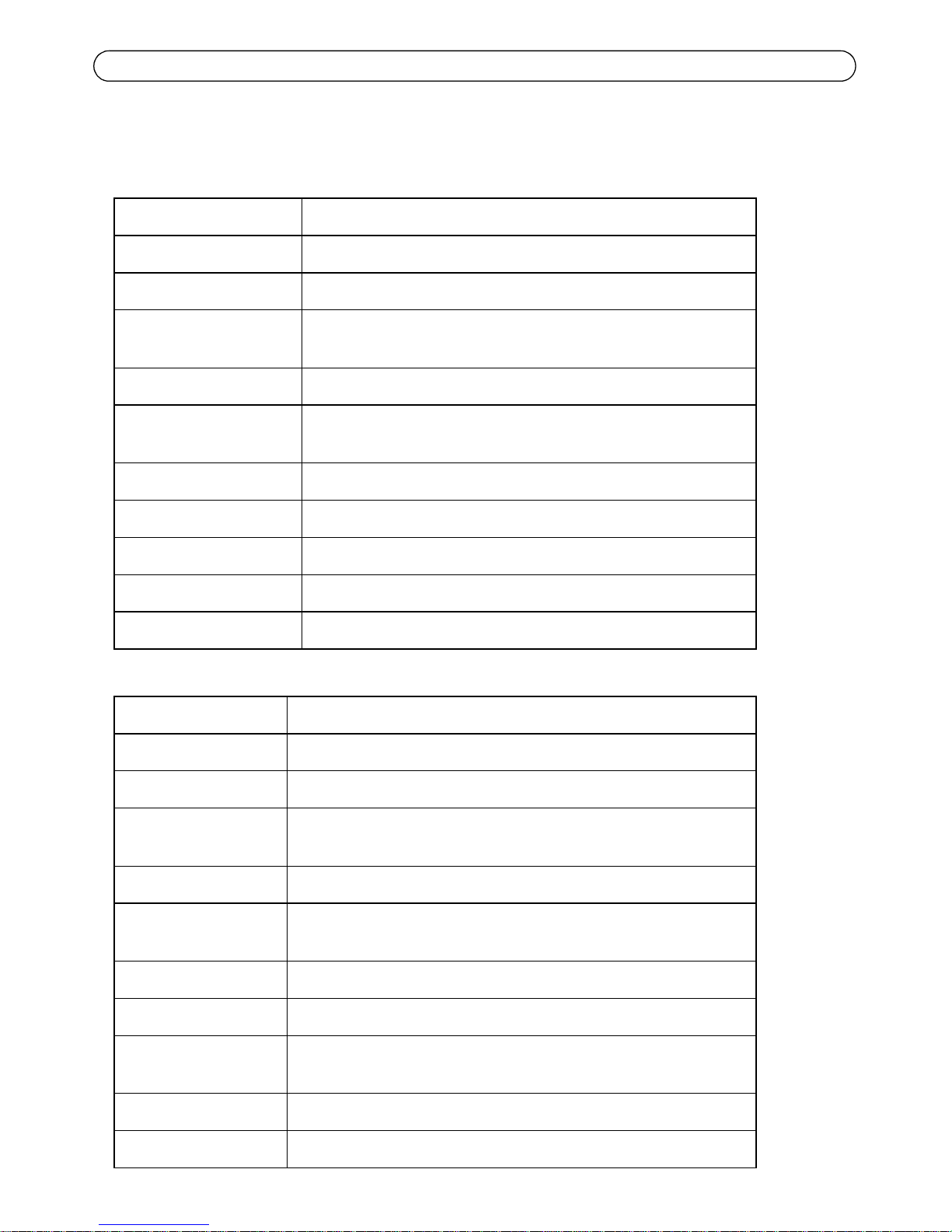
Package Contents
Item Models/variants/notes
Lighting Module • PoE Cat 5 cable
(for AXIS T90C20 Fixed Dome IR-LED)
• 18-56V DC Power Control cable
(for AXIS T90C10 IR-LED)
Printed materials AXIS T90C10/T90C20 Fixed Dome IR-LED User Guide
(this document), Axis Warranty Document
Page 6
Page 6 AXIS T90C10/T90C20 Fixed Dome IR-LED User Guide
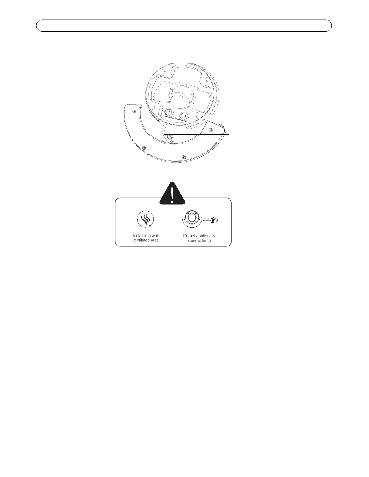
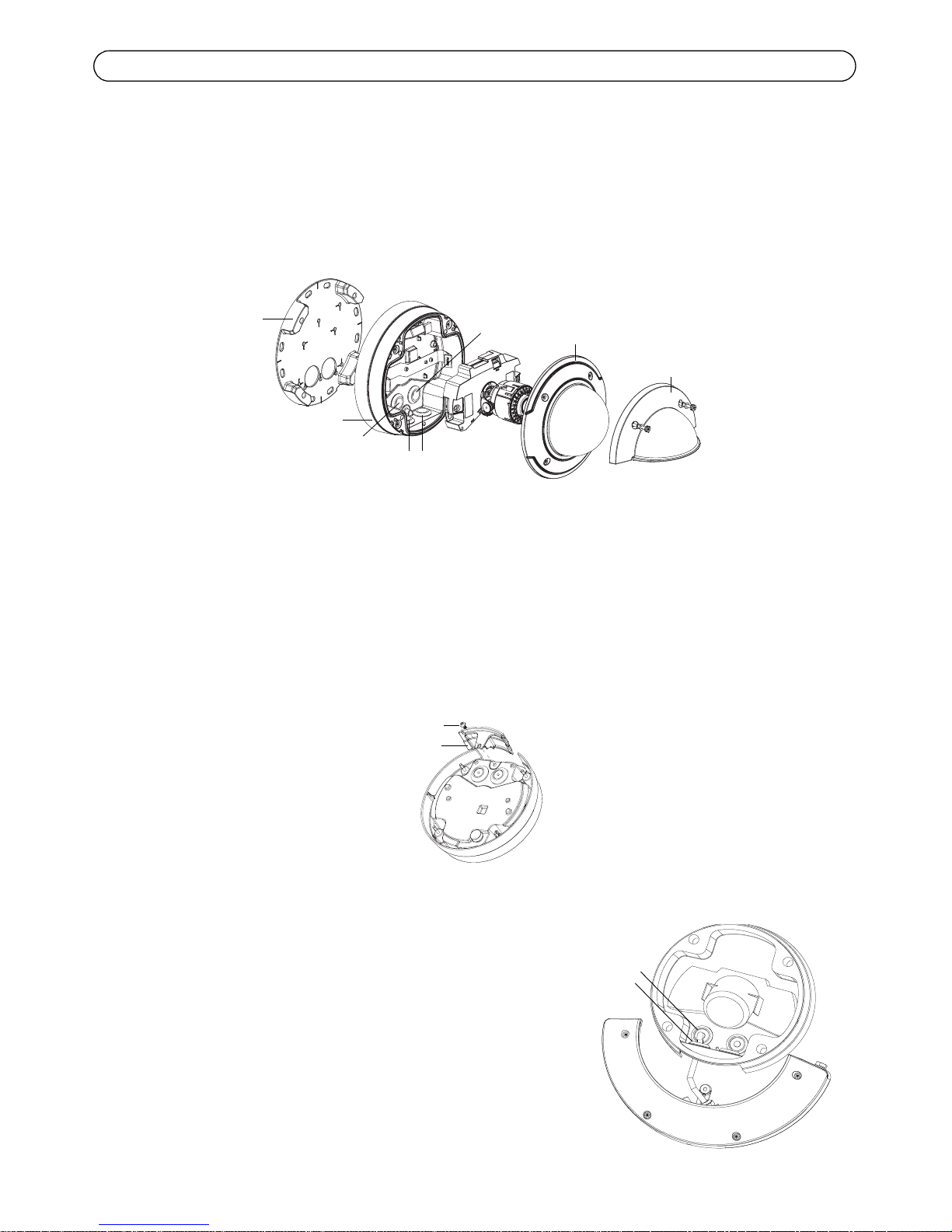
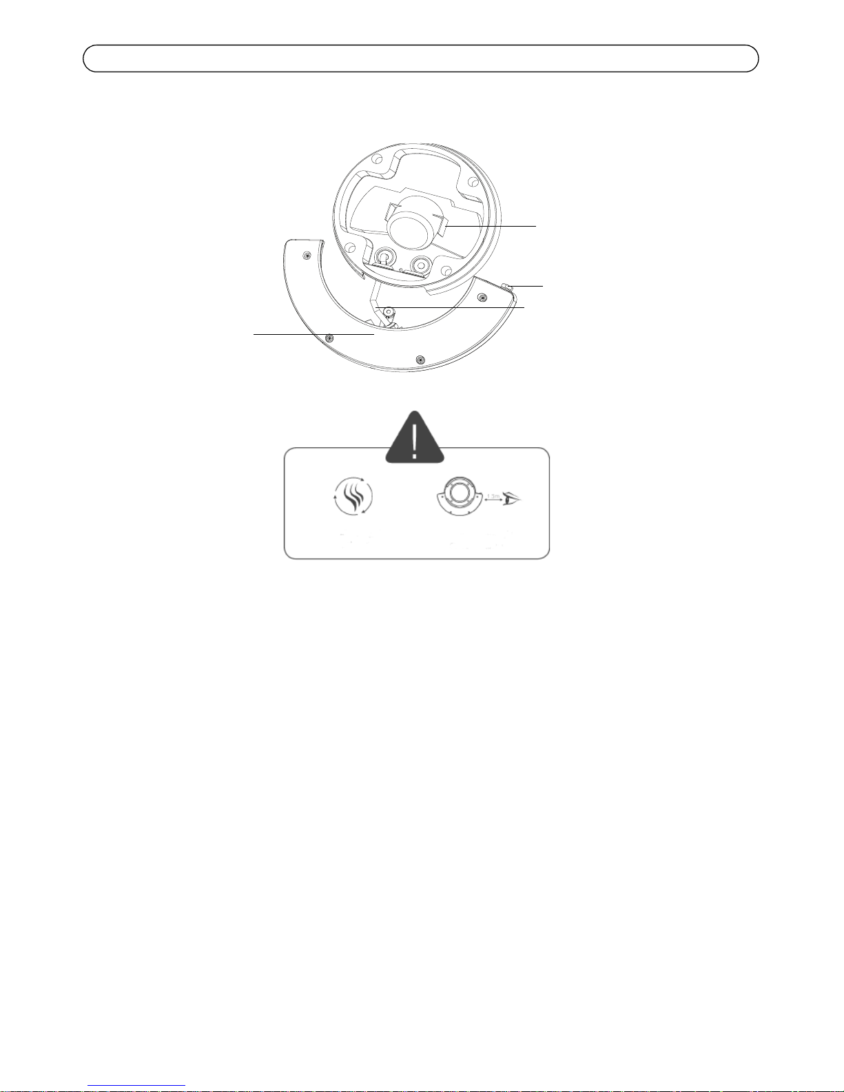
Hardware Overview
AXIS P33 Fixed Dome camera
Photocell
IR-LED
PoE Cat 5 or 18-56 V DC Power
(pre-mounted)
5-meter cable
Specifications subject to change without notice. Installation to be carried out by trained and qualified personnel.
Page 7
AXIS T90C10/T90C20 Fixed Dome IR-LED User Guide Page 7
ENGLISH
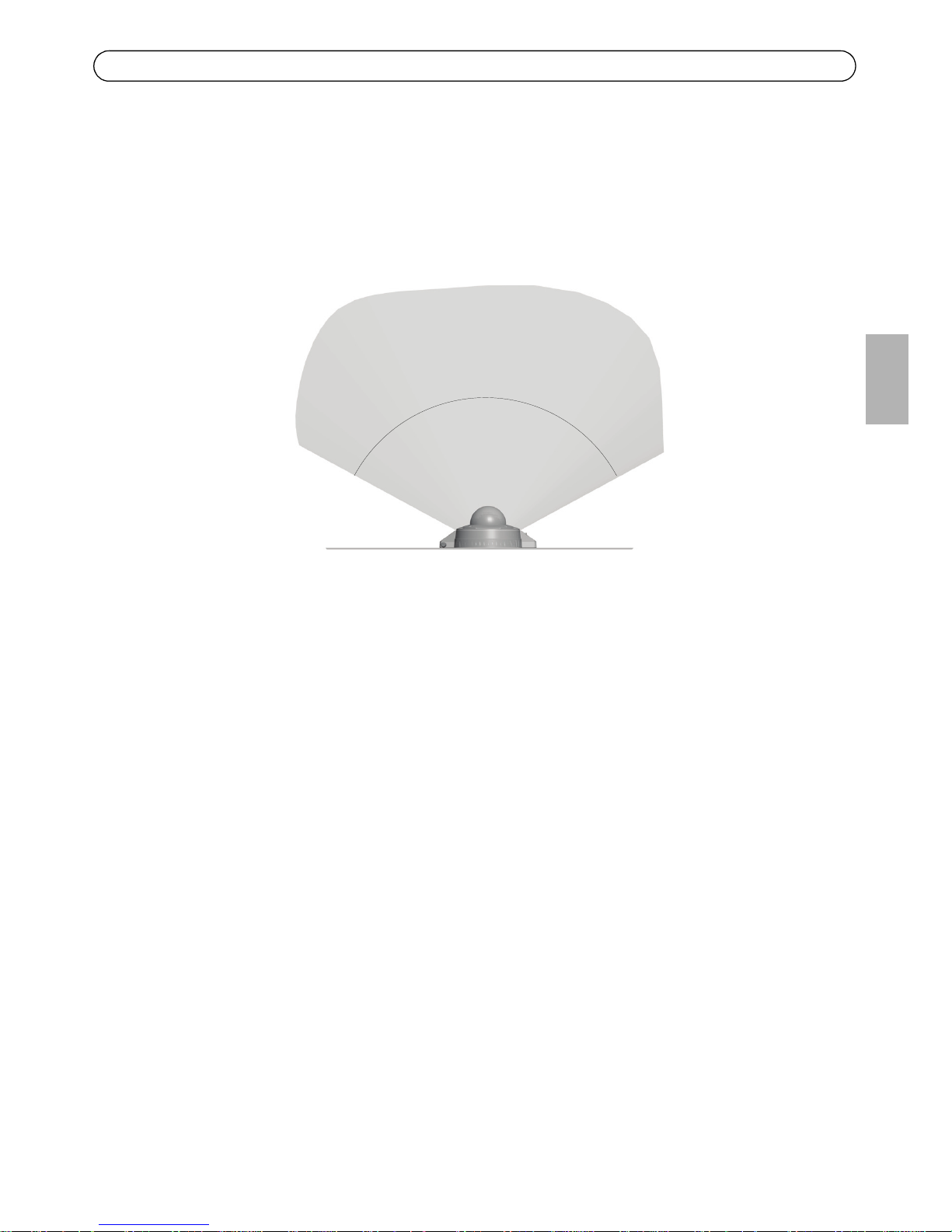
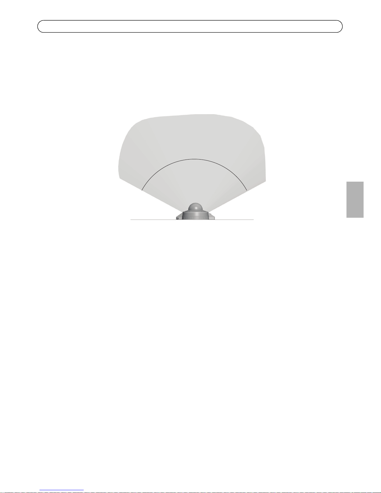
Recommendations
This Axis product is delivered with the LED block facing the front and this positioning is appropriate
for most installations; it is however possible to move the LED block to face other directions. See
page 10.
Use screws appropriate for your wall material.
20-30m
Max illumination
Less illumination Less illumination
120˚
Page 8
Page 8 AXIS T90C10/T90C20 Fixed Dome IR-LED User Guide
Installation
Notes:
• When the IR-LED is installed, the camera cables can only be routed through the wall (not along the wall).
•The
IR-LED is controlled by the level of ambient light which is detected by the unit's photocell. Ensure that
the photocell is not obstructed or covered.
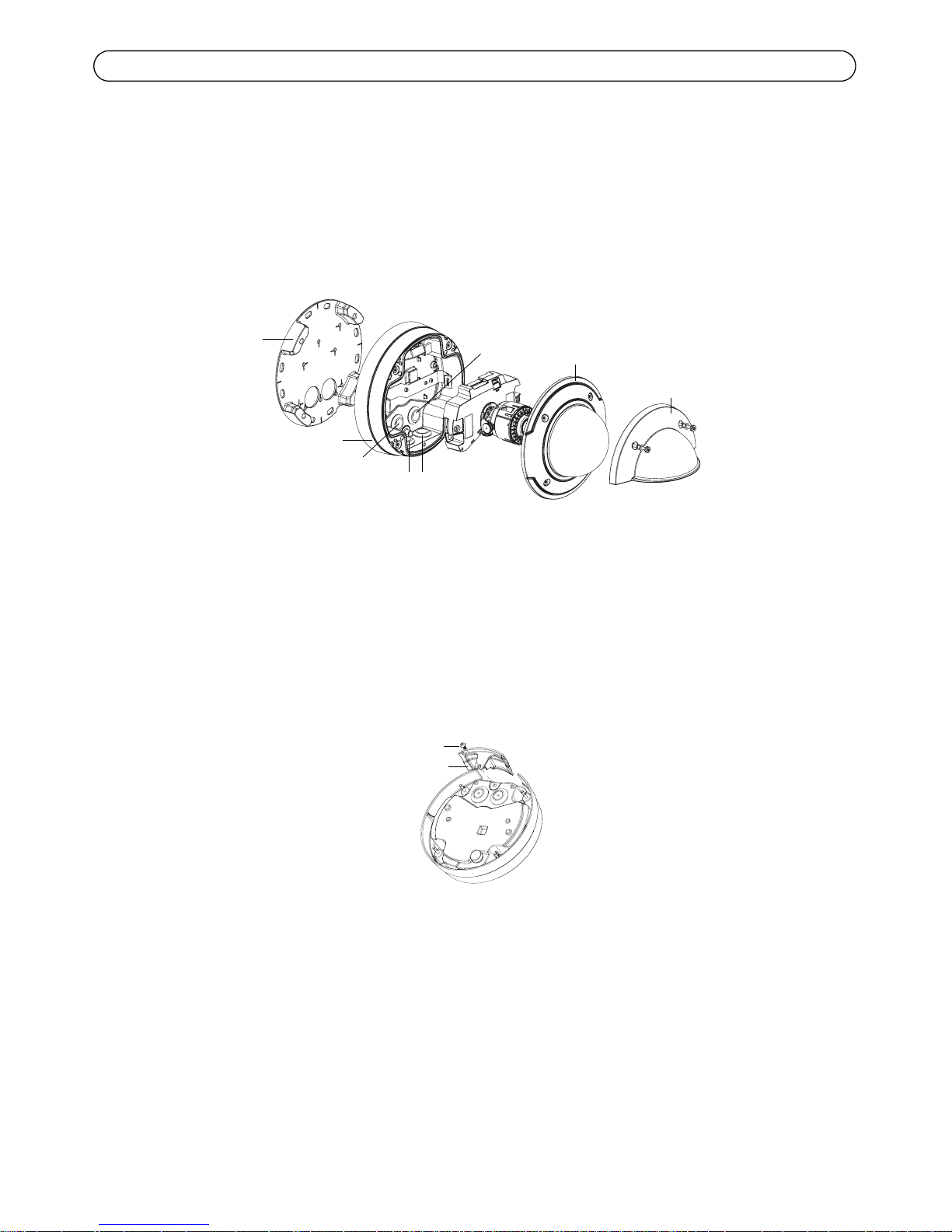
1. If the camera is already installed, disconnect power from the camera; remove the weather
shield, and the dome cover on the camera; remove the unit casing from the mounting bracket;
detach the camera unit.
If the camera is not already installed, attach the mounting bracket to the wall. Please check the
camera’s installation guide for this and further installation procedures.
2. Remove the side lid from the unit casing; save the screw.
If the camera lens is to face right or left, please read the information on page 10 before you
proceed.
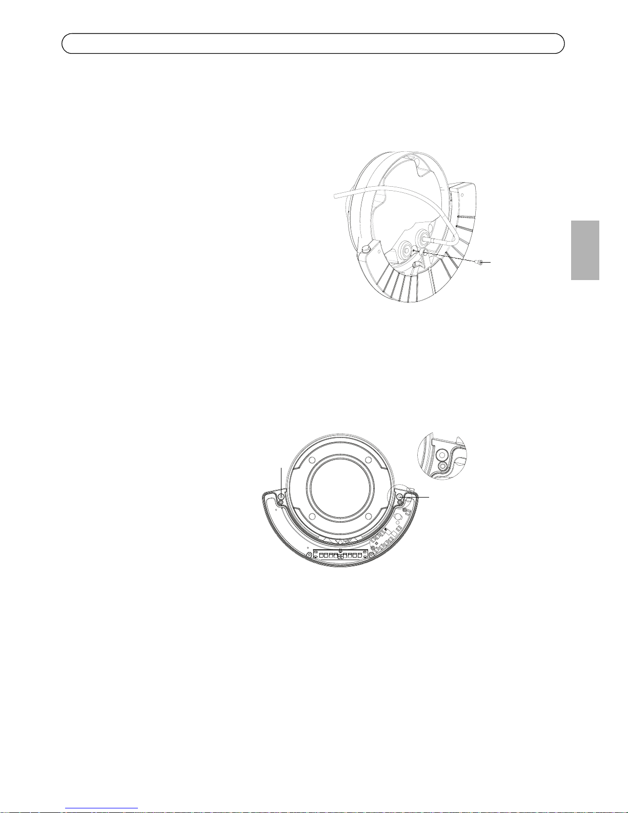
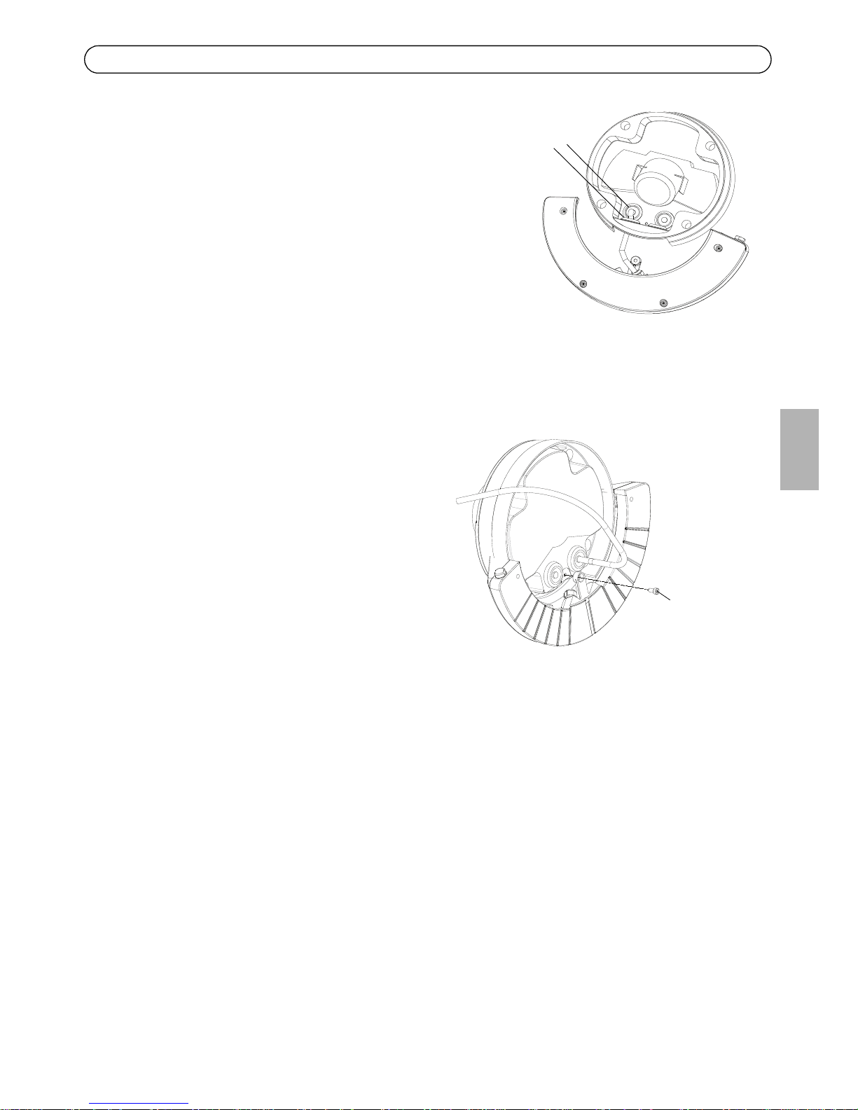
3. Remove the gasket from one of the side holes and
from the corresponding back hole in the unit casing,
for cabling. (The cable for the IR-LED should enter
the hole to the left in the unit casing)
Route the IR-LED cable through the side hole and
through the back hole in the unit casing.
4. Force the 2 gaskets on the cable through the side
hole.
Mounting bracket
Unit casing
Dome cover
Weather shield
Side holes
Back hole
Back hole
Side lid
Screw
Unit casing
Gaskets in side
and back holes
Page 9
AXIS T90C10/T90C20 Fixed Dome IR-LED User Guide Page 9
ENGLISH
5. Plug the gaskets into the side and back holes. The gaskets should fit snugly in the holes with no
folds or bends.
6. Place the IR-LED beneath the unit casing
aligning the screw hole on the back of the
IR-LED with the screw hole in the unit
casing; screw the IR-LED on to the unit
casing with the single screw.
7. Attach the unit casing to the mounting
bracket.
8. For vandal-resistant installation do the following:
a. Detach the cover on the IR-LED.
b. Screw the IR-LED to the wall with 2 screws.
c. Replace the cover after ensuring the gasket is in place.
9. Connect the network cable from the IR-LED to the PoE switch or midspan (AXIS T90C20); or
connect the DC cable to the PSU (AXIS T90C10).
10. To complete the camera installation please refer to the installation guide provided with the
network camera.
Screw IR-LED
Back view
Screw here
Screw here
Front view
Page 10
Page 10 AXIS T90C10/T90C20 Fixed Dome IR-LED User Guide
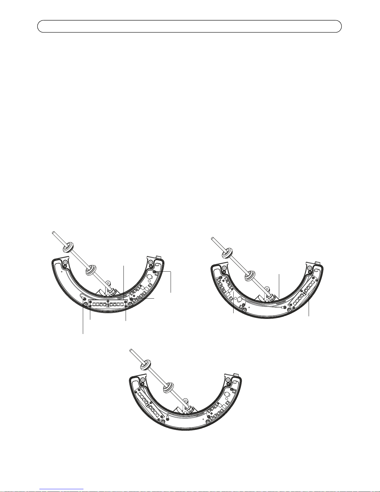
AXIS T90C20
When camera lens faces left
1. Remove 2 screws located on the top on either side of the LED block.
2. Unscrew the ground wire from the screw hole to the left and attach to a screw hole to the
right.
3. Align the LED block with the screw holes to the left and fasten the 2 screws again.
When camera lens faces right
1. Remove 2 screws located on the top on either side of the LED block.
2. Unscrew the ground wire from the screw hole to the left and attach to a screw hole to the
right.
3. Loosen the cable gland and pull a greater length of the cable so it can reach the left side of the
IR-LED.
4. Remove 2 screws on the control board and fasten the control board to the left.
5. Fix the LED block where the control board was with 2 screws.
LED block
2 screws on LED block
LED block to the left
LED block to the right
2 screws on control
board
LED block
Control board
LED block to the center
Cable gland
Ground wire
Page 11
AXIS T90C10/T90C20 Fixed Dome IR-LED User Guide Page 11
ENGLISH
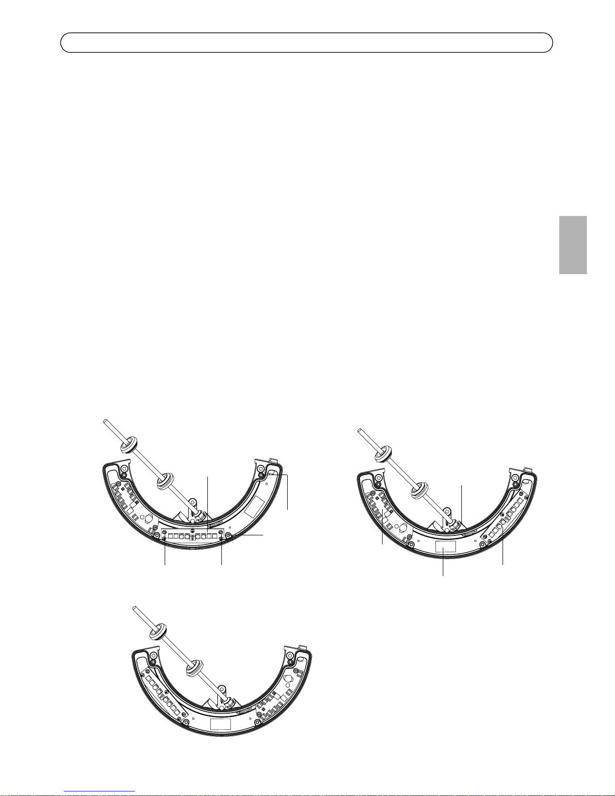
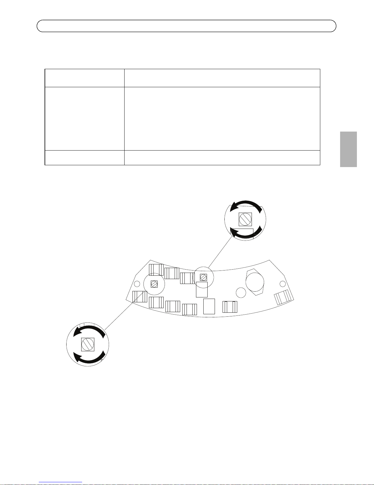
AXIS T90C10
When camera lens faces left
1. Remove 2 screws located on the top on either side of the LED block and detach the LED block.
2. Move the ferrite to the center (see image below).
3. Remove 2 screws on the control board and fasten the control board to the right.
4. Align the LED block with the screw holes to the left and fasten the 2 screws again.
When camera lens faces right
1. Remove 2 screws located on the top on either side of the LED block and detach the LED block.
2. Move the ferrite to the center (see image below).
3. Loosen the cable gland and pull a greater length of the cable so it can reach the left side of the
IR-LED.
4. Remove 2 screws on the control board and fasten the control board to the left.
5. Fix the LED block to the right (see image below).
LED block
2 screws on LED block
LED block to the left
LED block to the right
2 screws on control
board
LED block
Control board
LED block to the center
Cable gland
Ferrite
Page 12
Page 12 AXIS T90C10/T90C20 Fixed Dome IR-LED User Guide
Specifications
AXIS T90C10 IR-LED
AXIS T90C20 IR-LED
Model AXIS T90C10 Fixed Dome IR-LED
Power 18 - 56 V DC input, consumption: 13W
Type 850 nm semi-covert
Casing IP66- and NEMA 4X-rated, impact-resistant
aluminium casing and lexan cover
Angle 120°
Maximum illumination
distance
20 - 30m (67 - 98 ft) depending on environment and installation
Operating conditions -40 °C to +55 °C (-40 °F to 131 °F)
Accessories included Pre-mounted 5 m power cable
Dimensions 130 x 256 x 47 mm (5.1" x 11" x 1.8")
Weight 700 g (1.5 lb.) LB
Optional accessory Mains adaptor for T90C10
Model AXIS T90C20 Fixed Dome IR-LED
Power Power over Ethernet IEEE802.3af; consumption: 13W
Type 850 nm semi-covert
Casing IP66- and NEMA 4X-rated, impact-resistant
aluminium casing and lexan cover
Angle 120°
Maximum illumination
distance
20 - 30m (67 - 98ft) depending on environment and installation
Operating conditions -40 °C to +55 °C (-40 °F to 131 °F)
Accessories included Pre-mounted 5 m standard CAT 5 network cable
Recommended
accessories
AXIS PoE Midspan 1-Port
Dimensions 130 x 256 x 47 mm (5.1" x 11" x 1.8")
Weight 700 g (1.5 lb.) LB
Page 13
AXIS T90C10/T90C20 Fixed Dome IR-LED User Guide Page 13
ENGLISH
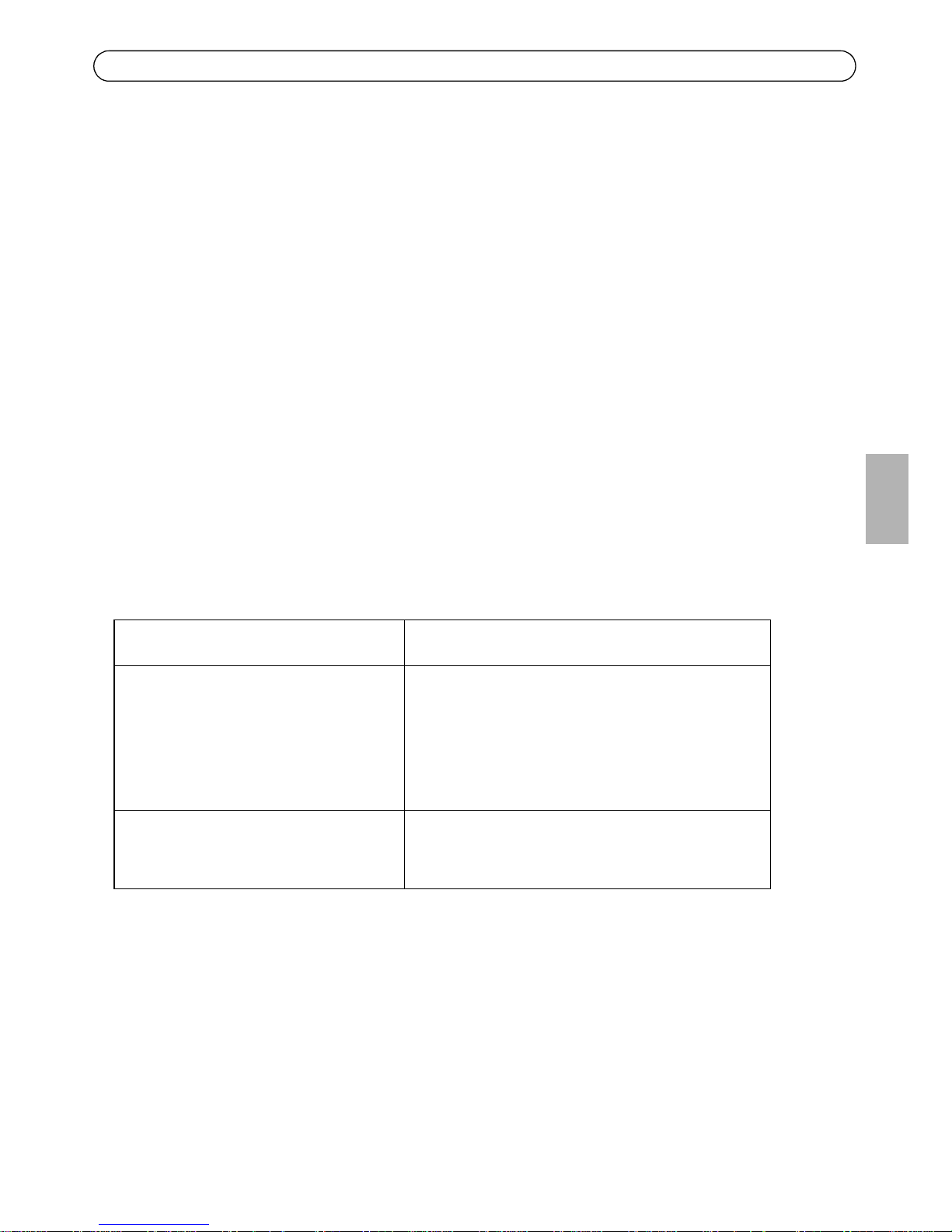
Troubleshooting
Problem Solution
IR-LED will not turn on • Check RJ45 connector is securely inserted
(AXIS T90C20 IR-LED)
• Check that supply voltage of PSU is 18-56V DC; ensure correct
polarity (AXIS T90C10 IR-LED)
• Adjust photocell (+ increases sensitivity; - decreases sensitivity)
• Check if photocell is working; cover photocell, LEDs should turn
on; if not, please contact Axis.
If the image is too bright Adjust power (see image below)
0%100%
-
Photocell adjuster
Adjust power
Move cables to see photocell adjuster
Page 14

Mesures de sécurité
Lisez attentivement le présent guide d’utilisation avant d’installer le produit. Conservez le guide d’utilisation si
vous souhaitez le consulter ultérieurement.
ATTENTION !
• Pour éviter d’endommager le produit Axis, utilisez l’emballage d’origine ou un équivalent pour le
transporter.
• Stockez le produit Axis dans un environnement sec et aéré.
• Utilisez uniquement des outils manuels pour l’installation du produit Axis, l’utilisation d’outils électriques
ou l’usage excessif de la force risque de l’endommager.
• N’utilisez ni produits chimiques, ni substances caustiques, ni nettoyeurs aérosol. Utilisez un linge humide
pour le nettoyage.
• Utilisez uniquement des accessoires et des pièces de rechange fournis ou recommandés par Axis.
• Ne tentez pas de réparer le produit vous-même, contactez Axis ou votre revendeur Axis pour tout problème
lié au service.
IMPORTANT !
• Ce produit Axis doit être utilisé conformément aux lois et réglementations locales en vigueur.
Page 15
Guide d'utilisation de l’AXIS T90C10/T90C20 DEL infrarouges pour dôme fixe Page 15
FRAN
Ç
AIS
AXIS T90C10/T90C20 DEL infrarouges pour
dôme fixe
Vous trouverez dans ce guide les instructions nécessaires à l’installation du système d’éclairage à
DEL infrarouges AXIS T90C10 / AXIS T90C20 sur les modèles suivants de caméras à dômes fixes :
• AXIS P3343-VE
• AXIS P3344-VE
• AXIS P3346-VE.
Pour installer la caméra, reportez-vous au guide d’installation fourni avec le produit.
Le guide se présente comme suit :
1.
Contenu de l’emballage
. Voir ci-dessous.
2.
Installation
, à la page 18.
3.
Caractéristiques techniques
, à la page 23.
Contenu de l’emballage
Article Modèles/variantes/remarques
Module d’éclairage • Câble PoE Cat-5
(pour AXIS T90C20 DEL infrarouges pour dôme
fixe )
• Câble d’alimentation 18-56 V CC
(pour AXIS T90C10 DEL infrarouges pour dôme
fixe)
Documentation Guide d’utilisation de l’AXIS T90C10/T90C20 DEL
infrarouges pour dôme fixe (le présent document),
document de garantie Axis
Page 16
Page 16 Guide d’utilisation de l’AXIS T90C10/T90C20 DEL infrarouges pour dôme fixe
Présentation du matériel
Caméra à dôme fixe AXIS P33
Cellule photoélectrique
DEL infrarouges
PoE Cat-5 ou alimentation 18-56 V CC
(prémonté)
Câble de 5 mètres
Les spécifications sont susceptibles d’être modifiées sans préavis.
L’installation doit être effectuée par du personnel formé et qualifié.
Installer dans un en
droit bien ventilé
Ne pas regarder contimellement le bloc à DEL
Page 17
Guide d'utilisation de l’AXIS T90C10/T90C20 DEL infrarouges pour dôme fixe Page 17
FRAN
Ç
AIS
Recommandations
Ce produit Axis est livré avec le bloc à DEL orienté vers l’avant. Ce positionnement est approprié
pour la plupart des installations. Il est cependant possible de déplacer ce bloc pour l’orienter dans
d’autres directions. Reportez-vous à la page 21.
Utilisez des vis adaptées au matériau de votre mur.
20-30m
120°
Maximum d’éclairage
Peu d’éclairagePeu d’éclairage
Page 18
Page 18 Guide d’utilisation de l’AXIS T90C10/T90C20 DEL infrarouges pour dôme fixe
Installation
Remarques :
• Après l’installation des DEL infrarouges, les câbles de la caméra peuvent seulement être acheminés à travers
le mur (pas le long du mur).
• L’éclairage par
DEL infrarouges est contrôlé par le niveau de lumière ambiante détecté via la cellule
photoélectrique de l’unité. Assurez-vous que cette cellule n’est ni obstruée ni couverte.
1. Si la caméra est déjà installée, mettez-la hors tension, retirez la protection étanche et la bulle
du dôme. Retirez ensuite le boîtier de l’unité du support mural et détachez la caméra.
Si la caméra n’est pas encore installée, fixez le support de fixation au mur. Reportez-vous au
guide d’installation de la caméra à ce sujet et pour en savoir plus sur les procédures
d’installation.
2. Retirez le couvercle latéral du boîtier de l’unité et mettez la vis de côté.
Si l’objectif de la caméra doit être orienté vers la droite ou la gauche, veuillez lire les
informations figurant à la page 21 avant toute manipulation.
Support de fixation
Boîtier de l’unité
Bulle du dôme
Protection étanche
Trous latéraux
Trou arrière
Trou arrière
Couvercle
Vis
Boîtier de l’unité
latéral
Page 19
Guide d'utilisation de l’AXIS T90C10/T90C20 DEL infrarouges pour dôme fixe Page 19
FRAN
Ç
AIS
3. Retirez le joint de l’un des trous latéraux ainsi que
celui du trou arrière correspondant sur le boîtier de
l’unité en vue du câblage. (le câble du module à DEL
infrarouges doit pénétrer dans le boîtier de l’unité
par le trou à gauche)
Faites passer le câble du module à DEL infrarouges
par le trou latéral, puis dans le trou arrière du boîtier
de l’unité.
4. Insérez les 2 joints sur le câble par le trou latéral.
5. Fixez les joints dans les trous latéraux et arrière. Les
joints doivent être parfaitement ajustés aux trous,
sans plis ni courbures.
6. Placez le module à DEL infrarouges sous le
boîtier de l’unité en alignant le trou de vis
situé à l’arrière du module à DEL infrarouges
avec le trou de vis situé sur le boîtier de
l’unité. Vissez le module à DEL infrarouges
sur le boîtier de l’unité à l’aide de la vis
unique.
7. Fixez le boîtier de l’unité au support de
fixation.
Joints des trous latéraux
et du trou arrière
Vissez le module à
Vue arrière
DEL infrarouges
Page 20

Page 20 Guide d’utilisation de l’AXIS T90C10/T90C20 DEL infrarouges pour dôme fixe
8. Pour les installations résistant au vandalisme, procédez comme suit :
a. Détachez le couvercle du module à DEL infrarouges.
b. Vissez ce module au mur à l’aide de 2 vis.
c. Remettez le couvercle en place en vous assurant que le joint est bien positionné.
9. Connectez le câble réseau du module à DEL infrarouges au commutateur ou à l’injecteur PoE
(AXIS T90C20), ou raccordez le câble CC au bloc d’alimentation (AXIS T90C10).
10. Pour terminer l’installation de la caméra, reportez-vous au guide d’installation fourni avec la
caméra réseau.
Vissez ici
Vissez ici
Vue de face
Page 21

Guide d'utilisation de l’AXIS T90C10/T90C20 DEL infrarouges pour dôme fixe Page 21
FRAN
Ç
AIS
AXIS T90C20
Lorsque l’objectif de la caméra est orienté vers la gauche
1. Retirez les 2 vis situées sur la partie supérieure, de part et d’autre du bloc à DEL.
2. Dévissez la vis du fil de terre à gauche et fixez le sur la vis de droite.
3. Alignez le bloc à DEL avec les trous de vis situés à gauche et serrez à nouveau les 2 vis.
Lorsque l’objectif de la caméra est orienté vers la droite
1. Retirez les 2 vis situées sur la partie supérieure, de part et d’autre du bloc à DEL.
2. Dévissez la vis du fil de terre à gauche et fixez le sur la vis de droite.
3. Desserrez le presse-étoupe et tirez une plus grande longueur de câble de manière à atteindre le
côté gauche du module à DEL infrarouges.
4. Retirez les 2 vis situées sur la carte de contrôle et fixez cette dernière sur la gauche.
5. À l’aide des 2 vis, fixez le bloc à DEL à l’endroit où la carte de contrôle se trouvait.
Bloc à DEL
2 vis sur le bloc à DEL
Bloc à DEL à gauche
Bloc à DEL à droite
2 vis sur la carte
de contrôle
Bloc à DEL
Carte de contrôle
Bloc à DEL au centre
Presse-étoupe
Fil de de terre
Page 22

Page 22 Guide d’utilisation de l’AXIS T90C10/T90C20 DEL infrarouges pour dôme fixe
AXIS T90C10
Lorsque l’objectif de la caméra est orienté vers la gauche
1. Retirer les 2 vis situées sur le dessus de chaque côté du bloc de LED et de détacher le bloc de
LED.
2. Déplacer la ferrite au centre (voir image ci-dessous).
3. Retirer les 2 vis de la carte de contrôle et fixer la carte de contrôle vers la droite.
4. Aligner le bloc de LED avec les trous de vis vers la gauche et fixer les 2 vis.
Lorsque l’objectif de la caméra est orienté vers la droite
1. Retirer les 2 vis situées sur le dessus de chaque côté du bloc de LED et de détacher le bloc de
LED.
2. Déplacer la ferrite au centre (voir image ci-dessous).
3. Desserrez le presse-étoupe et tirez une plus grande longueur de câble de maniére à atteindre le
côté gauche du module à DEL infrarouges.
4. Retirez les 2 vis situées sur la carte de contrôle et fixez cette dernière sur la gauche.
5. Fixez le bloc à DEL sur la droite (voir image ci-dessous).
Bloc à DEL
2 vis sur le bloc à DEL
Bloc à DEL à gauche
Bloc à DEL à droite
2 vis sur la carte
de contrôle
Bloc à DEL
Carte de contrôle
Bloc à DEL au centre
Presse-étoupe
Ferrite
Page 23

Guide d'utilisation de l’AXIS T90C10/T90C20 DEL infrarouges pour dôme fixe Page 23
FRAN
Ç
AIS
Caractéristiques techniques
AXIS T90C10 DEL infrarouges pour dôme fixe
AXIS T90C20 à DEL infrarouges
Modèle AXIS T90C10 DEL infrarouges pour dôme fixe
Alimentation Entrée 18 - 56 V CC, consommation : 13 W
Type 850 nm, application semi-couverte
Boîtier Boîtier aluminium et couvercle lexan,
certifiés IP66, NEMA 4X , résistants aux chocs
Angle 120°
Distance maximum
d’éclairage
20 à 30 m (67 à 98 pieds) selon l’environnement et l’installation
Conditions d’utilisation -40 à +55 ? (-40 à 131 °F)
Accessoires inclus Câble d’alimentation prémonté de 5 m
Dimensions 130 x 256 x 47 mm (5,1 x 11 x 1,8 po)
Poids 700 g (1,5 lb) LB
Accessoire en option Adapteur secteur pour T90C10
Modèle AXIS T90C20 DEL infrarouges pour dôme fixe
Alimentation Alimentation par Ethernet IEEE802.3af. Consommation : 13 W
Type 850 nm, application semi-couverte
Boîtier Boîtier aluminium et couvercle lexan,
certifiés IP66, NEMA 4X, résistants aux chocs
Angle 120°
Distance maximum
d’éclairage
20 à 30 m (67 à 98 pieds) selon l’environnement et l’installation
Conditions d’utilisation -40 à +55 ? (-40 à 131 °F)
Accessoires inclus Câble réseau standard CAT-5 prémonté de 5 m
Accessoires
recommandés
Injecteur PoE AXIS à 1 port
Dimensions 130 x 256 x 47 mm (5,1 x 11 x 1,8 po)
Poids 700 g (1,5 lb) LB
Page 24

Page 24 Guide d’utilisation de l’AXIS T90C10/T90C20 DEL infrarouges pour dôme fixe
Dépannage
Problème Solution
Le module à DEL
infrarouges ne s’allume
pas.
• Vérifiez que le connecteur RJ45 est correctement inséré.
(AXIS T90C20 à DEL infrarouges)
• Vérifiez que le bloc d’alimentation est bien sous une tension de
18-56 V CC. Vérifiez la polarité (AXIS T90C10 DEL infrarouges
pour dôme fixe).
• Réglez la cellule photoélectrique (+ pour augmenter la sensibilité
et - pour la diminuer).
• Vérifiez si la cellule photoélectrique fonctionne. Couvrez la
cellule : les DEL doivent s’allumer. Si ce n’est pas le cas, veuillez
contacter Axis.
Si l’image est trop claire. Réglez l’alimentation (voir l’image ci-dessous).
0%100%
-
Déplacez les câbles pour voir le dispositif de
réglage de la cellule photoélectrique.
Réglage de la
puissance
Réglage de la
cellule photoélectrique
Page 25

Page 26

Sicherheitsvorkehrungen
Bitte lesen Sie zunächst diese Bedienungsanleitung vollständig durch, bevor Sie mit der Installation Ihres
Produkts beginnen. Halten Sie die Bedienungsanleitung bereit, falls Sie darauf zurückgreifen müssen.
VORSICHT!
• Transportieren Sie das Axis-Produkt nur in der Originalverpackung bzw. in einer vergleichbaren Verpackung,
damit das Produkt nicht beschädigt wird.
• Lagern Sie das Axis-Produkt in einer trockenen und belüfteten Umgebung.
• Verwenden Sie keine elektrischen Werkzeuge zur Montage des Axis-Produkts, da diese das Produkt
beschädigen könnten.
• Verwenden Sie keine chemischen, ätzenden oder Aerosol-Reinigungsmittel. Verwenden Sie zur Reinigung
ein feuchtes Tuch.
• Verwenden Sie nur Zubehör und Ersatzteile, die von Axis empfohlen bzw. bereitgestellt wurden.
• Versuchen Sie nicht, das Produkt selbst zu reparieren. Wenden Sie sich bei Service-Angelegenheiten an Axis
oder an Ihren Axis-Händler.
WICHTIG!
• Verwenden Sie dieses Axis-Produkt unter Beachtung der geltenden rechtlichen Bestimmungen.
Page 27

AXIS T90C10/T90C20 Fixed-Dome-IR-LED Bedienungsanleitung Seite 27
DEUTSCH
AXIS T90C10/T90C20 Fixed-Dome-IR-LED
In dieser Anleitung wird die Anbringung des AXIS T90C10/ AXIS T90C20 IR-LED-Strahlers an
folgende unbewegliche Dome-Kameras beschrieben:
• AXIS P3343-VE
• AXIS P3344-VE
• AXIS P3346-VE.
Anweisungen zur Installation der Kamera finden Sie in der Installationsanleitung zu Ihrer Kamera.
In der Anleitung werden folgende Themen behandelt:
1.
Lieferumfang
. Siehe unten.
2.
Installation
, auf Seite 30.
3.
Spezifikationen
, auf Seite 35.
Lieferumfang
Komponente Modelle/Varianten/Anmerkungen
Beleuchtungsmodul • PoE-Cat 5-Kabel
(für AXIS T90C20 Fixed-Dome-IR-LED)
• 18-56 V Gleichstrom-Steuerkabel
(für AXIS T90C10 IR-LED)
Gedruckte Dokumente AXIS T90C10/T90C20 Fixed-Dome-IR-LED
Bedienungsanleitung (dieses Dokument),
Axis-Garantieerklärung
Page 28

Seite 28 AXIS T90C10/T90C20 Fixed-Dome-IR-LED Bedienungsanleitung
Hardwareübersicht
AXIS P33 Fixed-Dome-Kamera
Fotozelle
IR-LED
PoE-Cat 5- oder 18-56 V Gleichstrom-
(vormontiert)
Kabel (5 Meter)
Die Spezifikationen können jederzeit ohne Vorankündigung geändert werden.
Die Installation darf nur von geschulten und qualifizierten Mitarbeitern durchgeführt werden.
Zur Installation in gut
Bitte nicht direkt in die
Lampe schauen
belüfteten Bereichen!
Page 29

AXIS T90C10/T90C20 Fixed-Dome-IR-LED Bedienungsanleitung Seite 29
DEUTSCH
Empfehlungen
Der im Axis Produktpaket enthaltene LED-Block ist nach vorne ausgerichtet. Diese Position eignet
sich für die meisten Installationen. Sie können den LED-Block jedoch auch in andere Positionen
ausrichten. Siehe Seite 33.
Verwenden Sie Schrauben, die für das Wandmaterial geeignet sind.
20-30m
120°
Max Ausleuchtung
Min. Ausleuchtung
Min. Ausleuchtung
Page 30

Seite 30 AXIS T90C10/T90C20 Fixed-Dome-IR-LED Bedienungsanleitung
Installation
Hinweise:
• Wenn der IR-LED-Strahler montiert ist, können die Kamerakabel nur durch und nicht entlang der Wand
verlegt werden.
•Der
IR-LED-Strahler wird durch das Umgebungslicht gesteuert, das von der Fotozelle des Geräts erkannt
wird. Stellen Sie daher sicher, dass die Fotozelle nicht blockiert oder abgedeckt wird.
1. Wenn die Kamera bereits montiert ist, trennen Sie die Kamera von der Stromversorgung.
Entfernen Sie den Wetterschutz und die Kuppelabdeckung der Kamera. Nehmen Sie
anschließend das Kameragehäuse aus der Montagehalterung und die Kameraeinheit aus dem
Gehäuse heraus.
Wenn die Kamera noch nicht installiert wurde, befestigen Sie die Montagehalterung an der
Wand. Anweisungen hierzu und weitere Informationen finden Sie in der Installationsanleitung
zu Ihrer Kamera.
2. Entfernen Sie die Seitenabdeckung des Kameragehäuses. Legen Sie die Schrauben beiseite und
heben Sie sie auf.
Wenn das Kameraobjektiv nach rechts oder links ausgerichtet sein sollte, lesen Sie zunächst die
Informationen auf Seite 33, bevor Sie fortfahren.
Montagehalterung
Kameragehäuse
Kuppelabdeckung
Wetterschutz
Seitenlöcher
rückseitiges Kabelloch
rückseitiges Kabelloch
Seiten
Schraube
Kameragehäuse
abdeckung
Page 31

AXIS T90C10/T90C20 Fixed-Dome-IR-LED Bedienungsanleitung Seite 31
DEUTSCH
3. Entfernen Sie zur Verkabelung die Dichtung aus
einem Seitenloch und dem entsprechenden
rückseitigen Kabelloch des Kameragehäuses. (Das
Kabel des IR-LED-Strahlers muss durch das linke
rückseitige Kabelloch im Kameragehäuse geführt
werden).
Führen Sie das IR-LED-Kabel durch das seitliche
und rückseitige Kabelloch im Kameragehäuse.
4. Führen Sie die beiden Kabeldichtungen durch das
seitliche Kabelloch.
5. Drücken Sie die Dichtungen in das seitliche und
rückseitige Kabelloch. Die Dichtungen müssen
ohne Falten oder Krümmungen fest in den Löchern
sitzen.
6. Positionieren Sie den IR-LED-Strahler unten
am Kameragehäuse und richten Sie das
Schraubenloch auf der Rückseite des
IR-LED-Strahlers auf das Schraubenloch im
Kameragehäuse aus. Befestigen Sie mit der
einzelnen Schraube den IR-LED-Strahler am
Kameragehäuse.
7. Befestigen Sie das Kameragehäuse an der
Montagehalterung.
Dichtungen in den seitlichen
und rückseitigen Kabellöchern
IR-LED-Schraube
Rückansicht
Page 32

Seite 32 AXIS T90C10/T90C20 Fixed-Dome-IR-LED Bedienungsanleitung
8. Führen Sie die folgenden Schritte für eine vandalismus-geschützte Installation aus:
a. Nehmen Sie die Abdeckung des IR-LED-Strahlers ab.
b. Befestigen Sie den IR-LED mit zwei Schrauben an der Wand.
c. Stellen Sie sicher, dass die Dichtung korrekt positioniert ist und bringen Sie die Abdeckung
wieder an.
9. Schließen Sie das Netzwerkkabel am IR-LED und am PoE-Switch bzw. Midspan (AXIS T90C20)
an oder verbinden Sie das Gleichstromkabel mit der Stromversorgungseinheit (AXIS T90C10).
10. Schließen Sie die Installation der Kamera gemäß den Anweisungen in der Installationsanleitung
zu Ihrer Netzwerk-Kamera ab.
Hier drehen
Hier drehen
Vorderansicht
Page 33

AXIS T90C10/T90C20 Fixed-Dome-IR-LED Bedienungsanleitung Seite 33
DEUTSCH
AXIS T90C20
Wenn das Kameraobjektiv nach links zeigt:
1. Entfernen Sie die zwei Schrauben auf beiden Seiten auf dem LED-Block.
2. Lösen Sie den Erdungsdraht aus dem Schraubenloch links und befestigen Sie ihn an einem
Schraubenloch auf der rechten Seite.
3. Richten Sie den LED-Block an den Schraubenlöchern auf der linken Seite aus und ziehen Sie
beide Schrauben wieder fest.
Wenn das Kameraobjektiv nach rechts zeigt:
1. Entfernen Sie die zwei Schrauben auf beiden Seiten auf dem LED-Block.
2. Lösen Sie das Erdungsdraht aus dem linken Schraubenloch und befestigen Sie es an einem
Schraubenloch rechts.
3. Lösen Sie die Kabelverschraubung und ziehen Sie das Kabel bis zur linken Seite des
IR-LED-Strahlers. Lösen Sie die beiden Schrauben auf der Steuerungseinheit und befestigen Sie
anschließend die Steuerungseinheit auf der linken Seite. Befestigen Sie den LED-Block mit zwei
Schrauben an der ursprünglichen Position der Steuerungseinheit.
4. Lösen Sie die beiden Schrauben auf der Steuerungseinheit und befestigen Sie anschließend die
Steuerungseinheit auf der linken Seite.
5. Befestigen Sie den LED-Block mit zwei Schrauben an der ursprünglichen Position der
Steuerungseinheit.
LED-Block
2 Schrauben auf LED-Block
LED-Block auf der linken Seite
LED-Block auf der rechten Seite
2 Schrauben auf
Steuerungseinheit
LED-Block
Steuerungseinheit
LED-Block in der Mitte
Kabelverschraubung
Erdungsdraht
Page 34

Seite 34 AXIS T90C10/T90C20 Fixed-Dome-IR-LED Bedienungsanleitung
AXIS T90C10
Wenn das Kameraobjektiv nach links zeigt:
1. Entfernen Sie die zwei Schrauben auf beiden Seiten auf dem LED-Block und entfernen danch
den LED-Block.
2. Bewegen Sie den Ferrit in die Mitte (siehe Bild unten).
3. Entfernen Sie die 2 Schrauben der Steuerungseinheit und befestigen Sie die Steuerungseinheit
auf der rechten Seite.
4. Richten Sie die LED-Block mit den Schraublöchern auf der linken Seite aus und ziehen Sie die 2
Schrauben wieder an.
Wenn das Kameraobjektiv nach rechts zeigt:
1. Entfernen Sie die 2 Schrauben auf beiden Seiten auf dem LED-Block und entfernen danch den
LED-Block.
2. Bewegen Sie den Ferrit in die Mitte (siehe Bild unten).
3. Lösen Sie die Kabelverschraubung und ziehendas Kabel nach, damit es die linke Seite des
LED-Block erreichen kann.
4. Entfernen Sie die zwei Schrauben der Steuerungseinheit und befestigen Sie die
Steuerungseinheit auf der linken Seite.
5. Befestigen Sie den LED-Block auf der rechten Seite (siehe Bild unten).
LED-Block
2 Schrauben auf LED-Block
LED-Block auf der linken Seite
LED-Block auf der rechten Seite
2 Schrauben auf
Steuerungseinheit
LED-Block
Steuerungseinheit
LED-Block in der Mitte
Kabelverschraubung
Ferrit
Page 35

AXIS T90C10/T90C20 Fixed-Dome-IR-LED Bedienungsanleitung Seite 35
DEUTSCH
Spezifikationen
AXIS T90C10 IR-LED
AXIS T90C20 IR-LED
Modell AXIS T90C10 Fixed-Dome-IR-LED
Betrieb Netzeingang: 18 - 56 V Gleichstrom, Stromverbrauch: 13 W
Typ 850 nm halb verdeckt
Gehäuse IP66- und NEMA 4X-zertifiziert, schlagfest
Aluminiumgehäuse mit Abdeckung aus Lexan
Winkel 120°
Maximale Beleuchtungsweite Je nach Umgebung und Installationsstandort 20 - 30 m
Betriebsbedingungen -40 °C bis +55 °C
Im Lieferumfang enthaltenes
Zubehör
Vormontiertes Netzkabel (5 m)
Abmessungen 130 x 256 x 47 mm
Gewicht 700 g
Optinonales Zubehör Netzteil für T90C10
Modell AXIS T90C20 Fixed-Dome-IR-LED
Betrieb Power over Ethernet IEEE802.3af; Stromverbrauch: 13 W
Typ 850 nm halb verdeckt
Gehäuse IP66- und NEMA 4X-zertifiziert, schlagfest
Aluminiumgehäuse mit Abdeckung aus Lexan
Winkel 120°
MaximaleBeleuchtungsweite Je nach Umgebung und Installationsstandort 20 - 30 m
Betriebsbedingungen -40 °C bis +55 °C
Im Lieferumfang enthaltenes
Zubehör
Vormontiertes Standard-CAT 5-Netzwerkkabel (5 m)
Empfohlenes Zubehör AXIS PoE-Midspan 1 Anschluss
Abmessungen 130 x 256 x 47 mm
Gewicht 700 g
Page 36

Seite 36 AXIS T90C10/T90C20 Fixed-Dome-IR-LED Bedienungsanleitung
Fehlerbehebung
Problem Lösung
IR-LED-Strahler schaltet
sich nicht ein
• Vergewissern Sie sich, dass der RJ45-Stecker sicher eingesteckt
ist
(AXIS T90C20 IR-LED)
• Stellen Sie sicher, dass die SVE 18 bis 56 V Gleichstrom liefert und
die richtige Polarität eingestellt ist (AXIS T90C10 IR-LED)
• Stellen Sie die Fotozelle ein (+ erhöht die Empfindlichkeit; verringert die Empfindlichkeit)
• Prüfen Sie, ob die Fotozelle funktioniert. Verdecken Sie die
Fotozelle: Die LEDs sollten sich jetzt einschalten. Ist dies nicht der
Fall, wenden Sie sich an Axis.
Das Bild ist zu hell Passen Sie die Spannung an (siehe Abbildung unten)
Schieben Sie die Kabel zur Seite,
um an den Fotozellenregler zu gelangen
0%100%
-
+
Spannungsregler
Fotozellenregler
Page 37

Page 38

Precauzioni
Leggere per intero e con attenzione questa Guida per l'utente prima di installare il prodotto. Conservare la Guida
per l'utente per ulteriori riferimenti.
ATTENZIONE!
• Quando si trasporta un prodotto Axis, utilizzare l'imballo originale o un imballo equivalente per evitare
danni al prodotto.
• Conservare il prodotto Axis in un ambiente asciutto e ventilato.
• Per l'installazione del prodotto Axis, utilizzare solo attrezzi manuali, l'utilizzo di utensili elettrici o
l'applicazione di una forza eccessiva potrebbero danneggiare il prodotto.
• Non utilizzare sostanze chimiche, agenti caustici o detergenti aerosol. Utilizzare un panno umido per la
pulizia.
• Utilizzare solo accessori e parti di ricambio forniti o consigliati da Axis.
• Non tentare di riparare da soli il prodotto, ma contattare Axis o il rivenditore Axis per qualsiasi argomento
relativo all'assistenza tecnica.
IMPORTANTE!
• Questo prodotto Axis deve essere utilizzato in conformità alle leggi e alle regolamentazioni locali.
Page 39

Guida per l'utente del LED IR per cupola fissa AXIS T90C10/T90C20 Pagina 39
ITALIANO
LED IR per cupola fissa AXIS T90C10/T90C20
Questa guida fornisce le istruzioni per installare il LED IR per AXIS T90C10/ AXIS T90C20 con le
seguenti telecamere fisse a cupola:
• AXIS P3343-VE
• AXIS P3344-VE
• AXIS P3346-VE.
Per installare la telecamera, fare riferimento alla guida all'installazione fornita con il prodotto.
La guida fornisce informazioni sui seguenti argomenti:
1.
Contenuto della confezione
. Vedere di seguito.
2.
Installazione
, a pagina 42.
3.
Specifiche
, a pagina 47.
Contenuto della confezione
Elemento Modelli/varianti/note
Modulo di illuminazione • Cavo PoE Cat 5
(per LED IR per cupola fissa AXIS T90C20)
• Cavo di controllo alimentazione 18-56V CC
(per LED IR per AXIS T90C10 )
Materiali stampati Guida per l'utente di LED IR per cupola fissa AXIS
T90C10/T90C20 (questo documento), Documento di
garanzia Axis
Page 40

Pagina 40 Guida per l'utente del LED IR per cupola fissa AXIS T90C10/T90C20
Panoramica dell'hardware
Telecamera a cupola fissa AXIS P33
Fotocellula
LED IR
PoE Cat 5 o alimentazione 18-56 V CC
(pre-montato)
Cavo da 5 metri
Le specifiche tecniche possono essere modificate senza preavviso.
L'installazione deve essere eseguita da personale preparato e qualificato.
Installare in una zona
adeguatamente ventilata
Non fissare lo sguardo
sulla lampada
Page 41

Guida per l'utente del LED IR per cupola fissa AXIS T90C10/T90C20 Pagina 41
ITALIANO
Raccomandazioni
Questo prodotto Axis viene fornito con il blocco LED sulla parte anteriore e questo posizionamento
è adatto alla maggior parte delle installazioni; è comunque possibile spostare il blocco LED nelle
altre direzioni. Vedere pagina 45.
Utilizzare viti adatte al materiale della parete.
20-30m
120˚
Massima illuminazione
Minore illuminazione
Minore illuminazione
Page 42

Pagina 42 Guida per l'utente del LED IR per cupola fissa AXIS T90C10/T90C20
Installazione
Note:
• Quando il LED IR è installato, i cavi della telecamera possono essere fatti passare solo attraverso la parete
(non lungo la parete).
•Il
LED IR è controllato dal livello di luce ambientale rilevato dalla fotocellula dell'unità. Assicurarsi che la
fotocellula non sia ostruita o coperta.
1. Se la telecamera è già installata, scollegare alimentazione dalla telecamera; rimuovere la
schermatura contro gli agenti atmosferici e la copertura a cupola; rimuovere il rivestimento
dell’unità dalla staffa di montaggio; scollegare l'unità della telecamera.
Se la telecamera non è già installata, fissare la staffa di montaggio alla parete. Controllare la
guida all'installazione della telecamera per questa e le ulteriori procedure di installazione.
2. Rimuovere il coperchio laterale dall’involucro dell’unità; conservando la vite.
Se l'obiettivo della telecamera deve essere rivolto a destra o a sinistra, leggere le informazioni a
pagina 45 prima di procedere.
Staffa di montaggio
Involucro dell’unità
Copertura a cupola
Schermo di protezione contro
Fori laterali
Foro posteriore
Foro posteriore
gli agenti atmosferici
Copertura
Vite
Involucro dell’unità
laterale
Page 43

Guida per l'utente del LED IR per cupola fissa AXIS T90C10/T90C20 Pagina 43
ITALIANO
3. Rimuovere la guarnizione da uno dei fori laterali e
dal foro posteriore corrispondente nell’involucro
dell’unità, per il cablaggio. (Il cavo del LED IR deve
entrare nel foro sulla sinistra dell’involucro
dell’unità)
Far passare il cavo del LED IR attraverso il foro
laterale e il foro posteriore dell’involucro dell’unità.
4. Forzare le 2 guarnizioni sul cavo attraverso il foro
laterale.
5. Inserire le guarnizioni nei fori laterale e posteriore.
Controllare che le guarnizioni si inseriscano a fondo
nei fori, senza pieghe o curvature.
6. Collocare il LED IR sotto l’involucro
dell’unità allineando il foro della vite sul
retro del LED IR con il foro della vite
nell’involucro dell’unità; avvitare il LED IR
sul rivestimento di unità con l’unica vite.
7. Fissare l’involucro dell’unità alla staffa di
montaggio.
8. Per un’installazione a prova di manomissione eseguire le seguenti operazioni:
a. Scollegare la copertura del LED IR.
b. Avvitare il LED IR sulla parete con 2 viti.
c. Rimontare il coperchio dopo essersi assicurati che la guarnizione sia in posizione.
Guarnizioni nei fori
laterali e posteriori
Avvitare il
Vista posteriore
LED IR
Avvitare qui
Avvitare qui
Vista anteriore
Page 44

Pagina 44 Guida per l'utente del LED IR per cupola fissa AXIS T90C10/T90C20
9. Collegare al cavo di rete dal LED IR allo switch o midspan PoE (AXIS T90C20); oppure collegare
il cavo CC alla PSU (AXIS T90C10).
10. Per completare l'installazione della telecamera, fare riferimento alla guida per l'installazione
fornita con la telecamera di rete.
Page 45

Guida per l'utente del LED IR per cupola fissa AXIS T90C10/T90C20 Pagina 45
ITALIANO
AXIS T90C20
Quando l’obiettivo della telecamera è rivolto a sinistra
1. Rimuovere le 2 viti situate sulla parte superiore di ciascun lato del blocco dei LED.
2. Svitare il cavo di terra dal foro della vite sulla sinistra e collegarlo al foro filettato sulla destra.
3. Allineare il blocco dei LED con i fori filettati a sinistra e fissare nuovamente le 2 viti.
Quando l’obiettivo della telecamera è rivolto a destra
1. Rimuovere le 2 viti situate sulla parte superiore di ciascun lato del blocco dei LED.
2. Svitare il cavo di terra dal foro della vite sulla sinistra e collegarlo al foro filettato sulla destra.
3. Allentare il pressacavo e tirare una tratto di cavo più lungo, in modo che possa raggiungere il
lato sinistro del LED IR.
4. Rimuovere le 2 viti dalla scheda di controllo e fissare la scheda di controllo sulla sinistra.
5. Fissare il blocco dei LED dove la scheda di controllo era fissata con 2 viti.
Blocco dei LED
2 viti sul blocco dei LED
Blocco dei LED sulla sinistra
Blocco dei LED a destra
2 viti sulla scheda
di controllo
Blocco dei LED
Scheda di controllo
Blocco dei LED al centro
Pressacavo
Filo di massa
Page 46

Pagina 46 Guida per l'utente del LED IR per cupola fissa AXIS T90C10/T90C20
AXIS T90C10
Quando l’obiettivo della telecamera è rivolto a sinistra
1. Rimuovere le 2 viti situate sulla parte superiore di ciascun lato del blocco dei LED e staccare il
blocco dei LED.
2. Spostare la ferrite al centro (vedi immagine in basso).
3. Rimuovere le due viti della scheda di controllo e fissare la scheda di controllo sulla destra.
4. Allineare il blocco dei LED con i fori delle viti a sinistra ed stringere le viti nuovamente.
Quando l’obiettivo della telecamera è rivolto a destra
1. Rimuovere le 2 viti situate sulla parte superiore di ciascun lato del blocco dei LED e staccare il
blocco dei LED.
2. Spostare la ferrite al centro (vedi immagine in basso).
3. Svitare il blocco del cavo e allungare il cavo cosicche' possa raggiungere la parte sinistra dell
LED IR.
4. Rimuovere le due viti della scheda di controllo e fissare la scheda di controllo sulla sinistra.
5. Fissare il blocco LED sulla destra (vedi immagine in basso).
Blocco dei LED
2 viti sul blocco dei LED
Blocco dei LED sulla sinistra
Blocco dei LED a destra
2 viti sulla scheda
di controllo
Blocco dei LED
Scheda di controllo
Blocco dei LED al centro
Pressacavo
Ferrite
Page 47

Guida per l'utente del LED IR per cupola fissa AXIS T90C10/T90C20 Pagina 47
ITALIANO
Specifiche
LED IR per AXIS T90C10
LED IR per AXIS T90C20
Modello LD IR per cupola fissa AXIS T90C10
Alimentazione Ingresso 18 - 56 V CC, consumo: 13W
Tipo 850 nm, semi-discreto
Involucro Classe IP66 e NEMA 4X, involucro resistente agli urti
in alluminio e coperchio in lexan
Angolo 120°
Distanza massima di
illuminazione
20 - 30 m in funzione dell’ambiente e dell’installazione
Condizioni operative Da -40 °C a +55 °C
Accessori inclusi Cavo di alimentazione da 5 m pre-montato
Dimensioni 130 x 256 x 47 mm
Peso 700 g
Accessorio opzionale Alimentatore per la T90C10
Modello LED IR per cupola fissa AXIS T90C20
Alimentazione Power over Ethernet IEEE802.3af; consumo: 13W
Tipo 850 nm, semi-discreto
Involucro Classe IP66 e NEMA 4X, involucro resistente agli urti
in alluminio e coperchio in lexan
Angolo 120°
Distanza massima di
illuminazione
20 - 30 m in funzione dell’ambiente e dell’installazione
Condizioni operative Da -40 °C a +55 °C
Accessori inclusi Cavo di rete CAT 5 da 5 m pre-montato
Accessori consigliati AXIS PoE Midspan 1-Port
Dimensioni 130 x 256 x 47 mm
Peso 700 g
Page 48

Pagina 48 Guida per l'utente del LED IR per cupola fissa AXIS T90C10/T90C20
Risoluzione dei problemi
Problema Soluzione
Il LED IR non si accende • Controllare che il connettore RJ45 sia inserito saldamente
(LED IR per AXIS T90C20)
• Controllare che la tensione di alimentazione della PSU sia 18-56V
CC; assicurarsi che la polarità sia corretta (LED IR per AXIS
T90C10 )
• Regolare la fotocellula (+ aumenta la sensibilità, - la diminuisce)
• Controllare che la fotocellula funzioni; coprire la fotocellula, i LED
dovrebbero accendersi; in caso contrario contattare Axis.
Se l'immagine è troppo
luminosa
Regolare alimentazione (vedere l’immagine sottostante)
0%100%
-
Regolatore fotocellula
Regolatore potenza
Spostare i cavi per vedere la regolazione della fotocellula
Page 49

Page 50

Medidas preventivas
Lea atentamente la Guía del usuario antes de instalar el producto. Guarde la Guía del usario para futuras
consultas.
¡PRECAUCIÓN!
• A la hora de transportar el producto Axis, utilice el embalaje original o uno equivalente para no dañar el
producto.
• Guarde el producto Axis en un entorno seco y ventilado.
• Utilice solo herramientas manuales a la hora de instalar el producto Axis, ya que el empleo de herramientas
eléctricas o de una fuerza excesiva podría dañar el producto.
• No utilice productos químicos, agentes cáusticos ni limpiadores en aerosol. Utilice un paño húmedo para la
limpieza.
• Utilice únicamente accesorios y piezas de recambio suministrados o recomendados por Axis.
• No intente reparar el producto por sí mismo, póngase en contacto con Axis o con el distribuidor de Axis
para los temas de servicio técnico.
¡IMPORTANTE!
• Este producto Axis debe utilizarse de conformidad con la legislación y normativas locales.
Page 51

Guía del usuario de LED infrarrojo AXIS T90C10/T90C20 para cámara domo fija Página 51
ESPAÑOL
LED infrarrojo AXIS T90C10/T90C20 para
cámara domo fija
Esta guía proporciona instrucciones acerca de la instalación de AXIS T90C10/ AXIS T90C20 con LED
infrarrojo con las siguientes cámaras domo fijas:
• AXIS P3343-VE
• AXIS P3344-VE
• AXIS P3346-VE.
Para instalar la cámara, consulte la guía de instalación proporcionada con el producto.
El contenido de esta guía es el siguiente:
1.
Contenido del paquete
. Consulte la información siguiente.
2.
Instalación
, en la página 54.
3.
Especificaciones
, en la página 59.
Contenido del paquete
Artículo Modelos/variantes/notas
Módulo de iluminación • Cable Cat 5 PoE
(para Cámara domo fija AXIS T90C20 con LED
infrarrojo)
• Cable de control de alimentación 18-56 V CC
(para AXIS T90C10 con LED infrarrojo)
Material impreso Guía del usuario de LED infrarrojo AXIS
T90C10/T90C20 para cámara domo fija (este
documento), documento de garantía de Axis
Page 52

Página 52 Guía del usuario de LED infrarrojo AXIS T90C10/T90C20 para cámara domo fija
Presentación del hardware
Cámara domo fija AXIS P33
Célula fotoeléctrica
LED infrarrojo
Alimentación PoE Cat 5 o 18-56 V CC
(preinstalado)
Cable de 5 metros
Especificaciones sujetas a cambios sin previo aviso.
La instalación debe ser realizada por personal cualificado y con experiencia.
Installar en una zona
No mirar fijamente
bien ventilada
a la lámpara
Page 53

Guía del usuario de LED infrarrojo AXIS T90C10/T90C20 para cámara domo fija Página 53
ESPAÑOL
Recomendaciones
Este producto de Axis se entrega con el bloque de LED mirando hacia el frente y esta posición es
adecuada para la mayoría de las instalaciones; sin embargo, es posible mover el bloque de LED hacia
otras direcciones. Consulte la página 57.
Utilice los tornillos adecuados para el material de la pared.
20-30m
120°
Iluminación
máx
Menos iluminación
Menos iluminación
Page 54

Página 54 Guía del usuario de LED infrarrojo AXIS T90C10/T90C20 para cámara domo fija
Instalación
Notas:
• Una vez instalado el LED infrarrojo, sólo podrá guiar los cables de la cámara a través de la pared (no a lo
largo de la pared).
•El
LED infrarrojo se controla a través del nivel de la luz ambiente que se detecta mediante la célula
fotoeléctrica de la unidad. Asegúrese de que la célula fotoeléctrica no está ni obstruida ni cubierta.
1. Si la cámara ya está instalada, desconecte la alimentación de la cámara; retire la pantalla de
protección y la cubierta del domo de la cámara; retire la carcasa de la unidad de la escuadra de
montaje; separe la unidad de la cámara.
Si la cámara no está aún instalada, fije la escuadra de montaje a la pared. Consulte la guía de
instalación de la cámara para estas y otras instrucciones de instalación.
2. Retire la tapa lateral de la carcasa de la unidad; guarde el tornillo.
Si el objetivo de la cámara se va orientar hacia la derecha o la iziquierda, lea la siguiente
información de la página 57 antes de continuar.
Escuadra de montaje
Carcasa de la unidad
Cubierta del domo
Pantalla de protección
Orificios laterales
Orificio trasero
Orificio trasero
Tapa
Tornillo
Carcasa de la unidad
lateral
Page 55

Guía del usuario de LED infrarrojo AXIS T90C10/T90C20 para cámara domo fija Página 55
ESPAÑOL
3. Para realizar el cableado, retire la junta de uno de los
orificios laterales y del orificio trasero
correspondiente en la carcasa de la unidad. (El cable
para el LED infrarrojo debe entrar en el orificio en la
parte izquierda de la carcasa de la unidad.)
Pase el cable del LED infrarrojo a través del orificio
lateral así como del orificio trasero en la carcasa de
la unidad.
4. Pase las dos juntas del cable a través del orificio
lateral.
5. Coloque las juntas en los orificios laterales y traseros.
Las juntas deben encajar perfectamente en los
orificios sin dobleces ni curvas.
6. Coloque el LED infrarrojo debajo de la
carcasa de la unidad alineando el orificio del
tornillo en la parte trasera del LED infrarrojo
con el orificio del tornillo en la carcasa de la
unidad; atornille el LED infrarrojo a la
carcasa de la unidad con el tornillo suelto.
7. Fije la carcasa de la unidad a la escuadra de
montaje.
Juntas en orificios laterales
y orificios traseros
Tornillo de
Vista trasera
LED infrarrojo
Page 56

Página 56 Guía del usuario de LED infrarrojo AXIS T90C10/T90C20 para cámara domo fija
8. Para instalaciones resistentes a agresiones, haga lo siguiente:
a. Retire la cubierta del LED infrarrojo.
b. Atornille el LED infrarrojo a la pared con 2 tornillos.
c. Vuelva a colocar la cubierta después de asegurarse de que la junta está en su sitio.
9. Conecte el cable de red desde el LED infrarrojo al switch o midspan PoE (AXIS T90C20); o
conecte el cable de CC a la fuente de alimentación (AXIS T90C10).
10. Para finalizar la instalación de la cámara, consulte la guía de instalación proporcionada con la
cámara de red.
Atornille aquí
Atornille aquí
Vista frontal
Page 57

Guía del usuario de LED infrarrojo AXIS T90C10/T90C20 para cámara domo fija Página 57
ESPAÑOL
AXIS T90C20
Cuando el objetivo de la cámara está orientado hacia la izquierda
1. Retire 2 tornillos ubicados en la parte superior en el lado del bloque de LED.
2. Desatornille el cable de la conexión a tierra del orificio del tornillo a la izquierda y fíjelo a un
orificio de tornillo a la derecha.
3. Alinee el bloque de LED con los orificios de los tornillos a la izquierda y vuelva a apretar los dos
tornillos.
Cuando el objetivo de la cámara está orientado hacia la derecha
1. Retire 2 tornillos ubicados en la parte superior en el lado del bloque de LED.
2. Desatornille el cable de la conexión a tierra del orificio del tornillo a la izquierda y fíjelo a un
orificio de tornillo a la derecha.
3. Afloje la prensaestopas y pase una longitud superior del cable de modo que llegue al lado
izquierdo del LED infrarrojo.
4. Retire 2 tornillos del tablero de control y fíjelo a la izquierda.
5. Fije el bloque de LED donde estaba el tablero de control con 2 tornillos.
Bloque de LED
2 tornillos en el bloque de LED
Bloque de LED a la izquierda
Bloque de LED a la derecha
2 tornillos en el tablero
de control
Bloque de LED
Tablero de control
Bloque de LED en el centro
Prensaestopas
Cable de la conexión a tierra
Page 58

Página 58 Guía del usuario de LED infrarrojo AXIS T90C10/T90C20 para cámara domo fija
AXIS T90C10
Cuando el objetivo de la cámara está orientado hacia la izquierda
1. Retire 2 tornillos ubicados en uno de los lados de la parte superior del bloque de LED y
desmóntelo.
2. Mueva la ferrita hacia el centro (ver imagen más abajo).
3. Retire 2 tornillos de la tarjeta de control y fijela hacia la derecha.
4. Align the LED block with the screw holes to the left and fasten the 2 screws again.
Cuando el objetivo de la cámara está orientado hacia la derecha
1. Retire 2 tornillos ubicados en uno de los lados de la parte superior del bloque de LED y
desmóntelo.
2. Mueva la ferrita hacia el centro (ver imagen más abajo).
3. Suelte el prensaestopas y despliegue más extensión de cable para que llegue a la parte
izquierda del LED-IR.
4. Retire 2 tornillos de la tarjeta de control y fijela hacia la izquierda.
5. Fije el bloque LED hacia la derecha (ver imagen a continuación).
Bloque de LED
2 tornillos en el bloque de LED
Bloque de LED a la izquierda
Bloque de LED a la derecha
2 tornillos en el tablero
de control
Bloque de LED
Tablero de control
Bloque de LED en el centro
Prensaestopas
Ferrita
Page 59

Guía del usuario de LED infrarrojo AXIS T90C10/T90C20 para cámara domo fija Página 59
ESPAÑOL
Especificaciones
AXIS T90C10 con LED infrarrojo
AXIS T90C20 con LED infrarrojo
Modelo Cámara domo fija AXIS T90C10 con LED infrarrojo
Alimentación Entrada 18-56 V CC, consumo: 13 W
Tipo 850 mm semicubierto
Carcasa Carcasa de aluminio y cubierta de lexan a prueba de impactos,
IP66 y NEMA 4X
Ángulo 120°
Distancia de iluminación máxima 20 - 30 m (67 - 98 pies) según el entorno y la instalación
Condiciones de funcionamiento -40 °C a +55 °C (-40 °F a 131 °F)
Accesorios incluidos Cable de alimentación de 5 m preinstalado
Dimensiones 130 x 256 x 47 mm (5,1" x 11" x 1,8")
Peso 700 g (1,5 lb)
Accesorio opcional Fuente de alimentación para T90C10
Modelo Cámara domo fija AXIS T90C20 con LED infrarrojo
Alimentación Alimentación a través de Ethernet IEEE802.3af; consumo: 13 W
Tipo 850 mm semicubierto
Carcasa Carcasa de aluminio y cubierta de lexan a prueba de impactos,
IP66 y NEMA 4X
Ángulo 120°
Distancia de iluminación máxima 20 - 30 m (67 - 98 pies) según el entorno y la instalación
Condiciones de funcionamiento -40 °C a +55 °C (-40 °F a 131 °F)
Accesorios incluidos Cable de red estándar CAT 5 de 5 m preinstalado
Accesorios recomendados AXIS Midspan PoE de 1 puerto
Dimensiones 130 x 256 x 47 mm (5,1" x 11" x 1,8")
Peso 700 g (1,5 lb)
Page 60

Página 60 Guía del usuario de LED infrarrojo AXIS T90C10/T90C20 para cámara domo fija
Solución de problemas
Problema Solución
El LED infrarrojo no se
enciende
• Compruebe que el conector RJ45 está insertado de forma segura
(AXIS T90C20 con LED infrarrojo)
• Compruebe que el voltaje de la alimentación de la FA es de 18-56
V CC; asegúrese de que la polaridad es correcta (AXIS T90C10 con
LED infrarrojo)
• Ajuste la célula fotoeléctrica (+ aumenta la sensibilidad; disminuye la sensibilidad)
• Compruebe que la célula fotoeléctrica está funcionando; cubra la
célula fotoeléctrica, el LED debe encenderse; si no es el caso,
póngase en contacto con Axis.
Si la imagen es demasiado
brillante
Ajuste de potencia (vea la imagen a continuación)
Mueva los cables para mostrar el ajustador
de la célula fotoeléctrica
0%100%
-
Ajuste potencia
Ajustador de la célula fotoeléctrica
Page 61

Page 62

Page 63

User Guide Ver.1.1
AXIS T90C10/T90C20 Fixed Dome IR-LED Printed: June 2011
© Axis Communications AB, 2011
Part No. 43109
 Loading...