

Page 1
AXIS T90B Series
AXIS T90B15 W-LED
AXIS T90B25 W-LED
AXIS T90B35 W-LED
AXIS T90B20 IR-LED
AXIS T90B30 IR-LED
AXIS T90B40 IR-LED
Installation Guide
Page 2
Legal Considerations
Video and audio surveillance can be regulated by
laws that vary from country to country. Check the
laws in your local region before using this product
for surveillance purposes.
Liability
Every care has been taken in the preparation of this
document. Please inform your local Axis ofce of
any inaccuracies or omissions. Axis Communications
AB cannot be held responsible for any technical or
typographical errors and reserves the right to make
changes to the product and manuals without prior
notice. Axis Communications AB makes no warranty
of any kind with regard to the material contained
within this document, including, but not limited to,
the implied warranties of merchantability and tness
for a particular purpose. Axis Communications AB
shall not be liable nor responsible for incidental
or consequential damages in connection with the
furnishing, performance or use of this material. This
product is only to be used for its intended purpose.
Intellectual Property Rights
Axis AB has intellectual property rights relating to
technology embodied in the product described in this
document. In particular, and without limitation, these
intellectual property rights may include one or more
of the patents listed at www.axis.com/patent.htm and
one or more additional patents or pending patent
applications in the US and other countries.
Equipment Modications
This equipment must be installed and used in
strict accordance with the instructions given in
the user documentation. This equipment contains
no user-serviceable components. Unauthorized
equipment changes or modications will invalidate
all applicable regulatory certications and approvals.
Trademark Acknowledgments
AXIS COMMUNICATIONS, AXIS, ETRAX, ARTPEC
and VAPIX are registered trademarks or trademark
applications of Axis AB in various jurisdictions. All
other company names and products are trademarks or
registered trademarks of their respective companies.
Regulatory Information
Europe
This product complies with the applicable
CE marking directives and harmonized standards:
• Electromagnetic Compatibility (EMC)
Directive 2004/108/EC. See Electromagnetic
Compatibility (EMC) on page 2 .
• Low Voltage (LVD) Directive 2006/95/EC. See
Safety on page 3 .
• Restrictions of Hazardous Substances (RoHS)
Directive 2011/65/EU. See Disposal and
Recycling on page 3 .
A copy of the original declaration of conformity
may be obtained from Axis Communications AB. See
Contact Information on page 3 .
Electromagnetic Compatibility (EMC)
This equipment has been designed and tested to fulll
applicable standards for:
• Radio frequency emission when installed
according to the instructions and used in its
intended environment.
• Immunity to electrical and electromagnetic
phenomena when installed according to
the instructions and used in its intended
environment.
USA
This equipment has been tested using a shielded
network cable (STP) and found to comply with the
limits for a Class B digital device, pursuant to part 15
of the FCC Rules. These limits are designed to provide
reasonable protection against harmful interference in
a residential installation. This equipment generates,
uses and can radiate radio frequency energy and,
if not installed and used in accordance with the
instructions, may cause harmful interference to radio
communications. However, there is no guarantee that
interference will not occur in a particular installation.
If this equipment does cause harmful interference
to radio or television reception, which can be
determined by turning the equipment off and on, the
user is encouraged to try to correct the interference
by one or more of the following measures:
• Reorient or relocate the receiving antenna.
• Increase the separation between the equipment
and receiver.
• Connect the equipment into an outlet on a
circuit different from that to which the receiver
is connected.
• Consult the dealer or an experienced radio/TV
technician for help.
The product shall be connected using a shielded
network cable (STP) that is properly grounded.
Canada
This Class B digital apparatus complies with Canadian
ICES-003. The product shall be connected using
a shielded network cable (STP) that is properly
grounded.
Cet appareil numérique de la classe B est confome à
la norme NMB-003 du Canada. Le produit doit être
connecté à l'aide d'un câble réseau blindé (STP) qui
est correctement mis à la terre.
Europe
This digital equipment fullls the requirements for RF
emission according to the Class B limit of EN 55022.
The product shall be connected using a shielded
network cable (STP) that is properly grounded.
This product fullls the requirements for immunity
according to EN 61000-6-1 residential, commercial
and light-industrial environments.
This product fullls the requirements for immunity
according to EN 61000-6-2 industrial environments.
Page 3
Australia/New Zealand
This digital equipment fullls the requirements
for RF emission according to the Class B limit of
AS/NZS CISPR 22. The product shall be connected
using a shielded network cable (STP) that is properly
grounded.
Korea
이 기기는 가정용(B급) 전자파적합기기로서
주로 가정에서 사용하는 것을 목적으로 하며,
모든 지역에서 사용할 수 있습니다. 적절히
접지된 STP (shielded twisted pair) 케이블을
사용하여 제품을 연결 하십시오.
Safety
Photobiological Safety
This product fullls the requirements for
photobiological safety according to IEC/EN 62471
(risk group 2).
Disposal and Recycling
When this product has reached the end of its
useful life, dispose of it according to local laws
and regulations. For information about your
nearest designated collection point, contact your
local authority responsible for waste disposal. In
accordance with local legislation, penalties may be
applicable for incorrect disposal of this waste.
Europe
This symbol means that the product shall
not be disposed of together with household or
commercial waste. Directive 2012/19/EU on waste
electrical and electronic equipment (WEEE) is
applicable in the European Union member states.
To prevent potential harm to human health and the
environment, the product must be disposed of in an
approved and environmentally safe recycling process.
For information about your nearest designated
collection point, contact your local authority
responsible for waste disposal. Businesses should
contact the product supplier for information about
how to dispose of this product correctly.
This product complies with the requirements of
Directive 2011/65/EU on the restriction of the use
of certain hazardous substances in electrical and
electronic equipment (RoHS).
China
This product complies with the requirements
of the legislative act Administration on the Control of
Pollution Caused by Electronic Information Products
(ACPEIP).
Contact Information
Axis Communications AB
Emdalavägen 14
223 69 Lund
Sweden
Tel: +46 46 272 18 00
Fax: +46 46 13 61 30
www.axis.com
Support
Should you require any technical assistance, please
contact your Axis reseller. If your questions cannot
be answered immediately, your reseller will forward
your queries through the appropriate channels to
ensure a rapid response. If you are connected to the
Internet, you can:
• download user documentation and software
updates
• nd answers to resolved problems in the FAQ
database. Search by product, category, or
phrase
• report problems to Axis support staff by logging
in to your private support area
• chat with Axis support staff (selected countries
only)
• visit Axis Support at www.axis.com/techsup/
Learn More!
Visit Axis learning center www.axis.com/academy/ for
useful trainings, webinars, tutorials and guides.
Page 4

Page 5

AXIS T90B Series
Safety Information
Read through this Installation Guide carefully before installing the product.
Keep the Installation Guide for future reference.
Hazard Levels
DANGER
Indicates a hazardous situation which, if not
avoided, will result in death or serious injury.
WARNING
Indicates a hazardous situation which, if not
avoided, could result in death or serious injury.
CAUTION
Indicates a hazardous situation which, if not
avoided, could result in minor or moderate injury.
NONONOTICETICE
TICE
Indicates a situation which, if not avoided, could
result in damage to property.
Other Message Levels
Important Indicates signicant information which is
essential for the product to function correctly.
Note Indicates useful information which helps in
getting the most out of the product.
5
Page 6

AXIS T90B Series
Safety Instructions
WARNING
• The Axis product shall be installed by a trained professional.
NONONOTICETICE
TICE
• The Axis product shall be used in compliance with local laws
and regulations.
• Store the Axis product in a dry and ventilated environment.
• Avoid exposing the Axis product to shocks or heavy pressure.
• Do not install the product on unstable brackets, surfaces or
walls.
• Use only applicable tools when installing the Axis product.
Excessive force could cause damage to the product.
• Do not use chemicals, caustic agents, or aerosol cleaners. Use a
clean cloth dampened with pure water for cleaning.
• Use only accessories that comply with technical specication of
the product. These can be provided by Axis or a third party.
• Use only spare parts provided by or recommended by Axis.
• Do not attempt to repair the product by yourself. Contact Axis
support or your Axis reseller for service matters.
Transportation
NONONOTICETICE
TICE
• When transporting the Axis product, use the original packaging
or equivalent to prevent damage to the product.
6
Page 7
AXIS T90B Series
Installation Guide
This Installation Guide provides instructions for installing AXIS T90B Series.
Installation Steps
1. Make sure the package contents, tools and other materials
necessary for the installation are in order. See page 7 .
2. Study the hardware overview. See page 8 .
3. Study the specications. See page 14.
4. Install the hardware. See page 15.
Package Contents
• AXIS T90B Illuminator including power cable
• 1 pre-mounted diverging lens
• 2 separate diverging lenses
Optional Accessories
• Mounting brackets
• Remote control
• Diverging lens with additional angle
• Power supply
For information about available accessories, see www.axis.com
7
Page 8
AXIS T90B Series
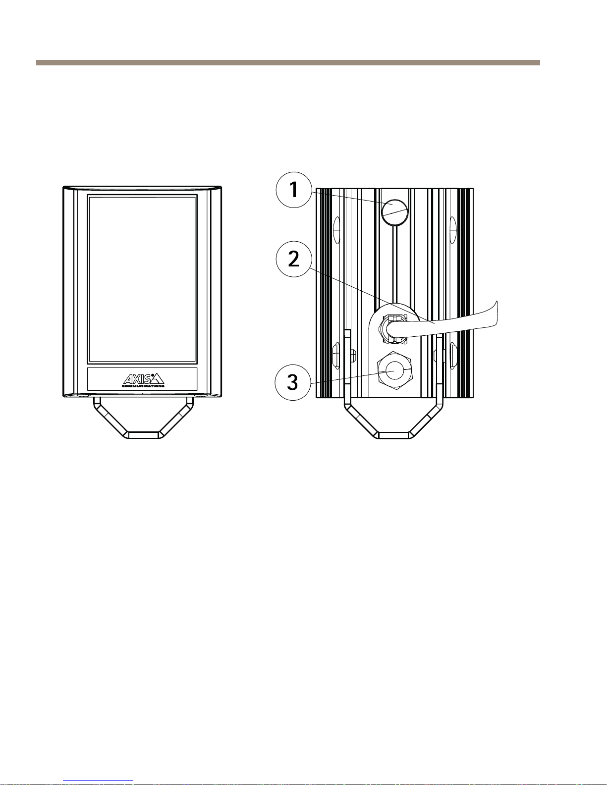
Hardware Overview
Illuminator
1
Photocell
2
Cable
3
Breather gland
8
Page 9
AXIS T90B Series
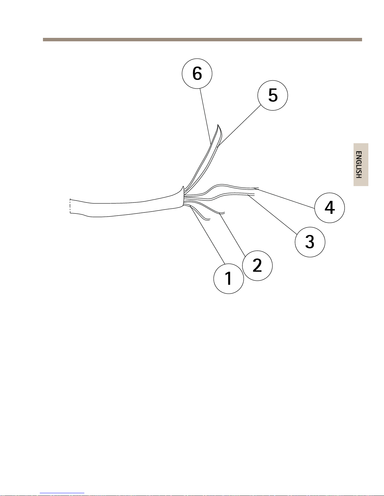
1
Power cable (red)
2
Power cable (black)
3
Photocell cable (white)
4
Photocell cable (yellow)
5
Telemetry cable (purple)
6
Telemetry cable (orange)
9
Page 10
AXIS T90B Series
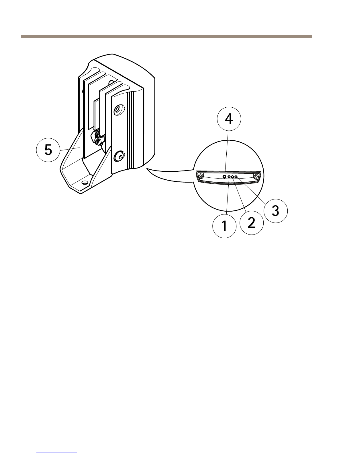
1
Red LED indicator
2
Amber LED indicator
3
Green LED indicator
4
Remote control receiver
5
Mounting bracket (pre-mounted)
10
Page 11

AXIS T90B Series
AXIS T90B40 IR-LED
1
Cables
2
Mounting bracket (pre-mounted)
3
Bolt
Optional Accessories
Remote Control
For information how to use the remote control, see Access the Product.
11
Page 12

AXIS T90B Series
1
POWER ADJUST buttons
2
PHOTOCELL ADJUST buttons
3
TIMER buttons
4
Photocell disable button
5
DIM button
6
RESET button
7
STATUS button
8
Disable remote control setup button
9
TELEMETRY button
Mounting Brackets
To install the product using a compatible bracket from AXIS T90B
Mounting Accessories, see the Installation Guide delivered separately with
the mounting bracket.
12
Page 13

AXIS T90B Series
LED Indicators
There are three colored LED indicators on the base of the illuminator which
provide operating and status information. The color status depends on
the current operating mode:
• Programming Mode
• Normal Operating Mode
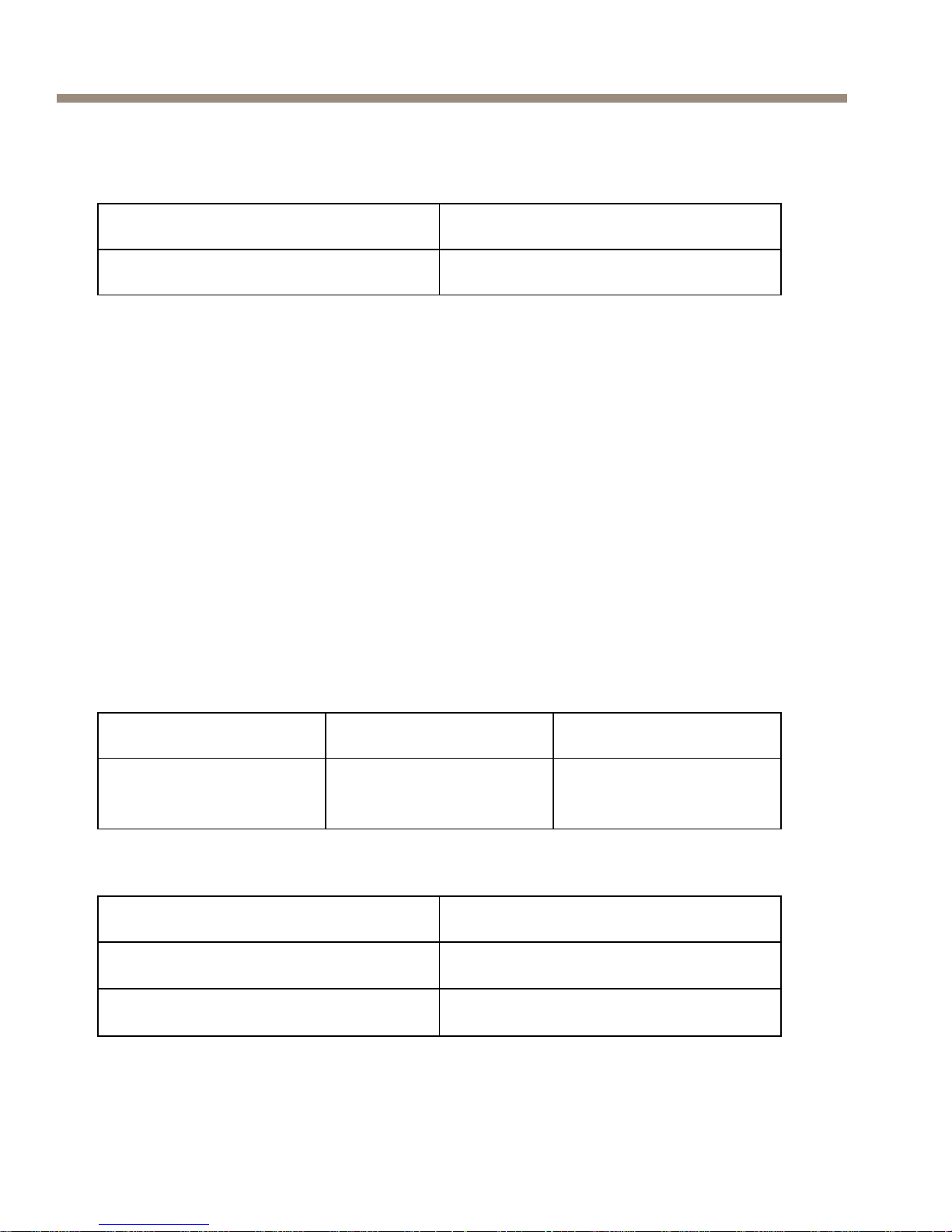
Programming Mode
LED Indicator Indicated Behavior
Solid Green
Power on
Flashing Green
Remote control IR receiver error
Solid Amber
Illuminator receiving valid
command from remote control
Flashing Amber Illuminator in Programming Mode
Solid Red
Internal LED error
Flashing Red
Input voltage supply error*
Normal Operating Mode
LED Indicator Indicated Behavior
Solid Green
Power on
Flashing Green
Remote control IR receiver error
13
Page 14
AXIS T90B Series
Normal Operating Mode (Continued)
Solid Amber Input voltage level error*
Solid Red
Internal LED error
*Once the voltage error has been corrected, disable the remote control
setup or restart the illuminator to turn the status LED off.
Connectors and Buttons
For specications and operating conditions, see page 14.
Power Connector
• AC/DC power connector
Specications
Operating Conditions
Product Temperature Humidity
AXIS T90B Series -50 °C to 50 °C
(-58 °F to 122 °F)
10–100% RH (condensing)
Power Consumption
Product Value
AXIS T90B15 W-LED
12–24 V AC/DC, max 12 W
AXIS T90B20 IR-LED
12–24 V AC/DC, max 24 W
14
Page 15

AXIS T90B Series
AXIS T90B25 W-LED
12–24 V AC/DC, max 48 W
AXIS T90B30 IR-LED
12–24 V AC/DC, max 24 W
AXIS T90B35 W-LED
12–24 V AC/DC, max 48 W
AXIS T90B40 IR-LED
12–24 V AC/DC, max 96 W
For more information about power consumption, see Technical
Specications on page 29
Install the Hardware
To install the product using a compatible bracket from AXIS T90B
Mounting Accessories, see the Installation Guide delivered separately with
the mounting bracket.
15
Page 16

AXIS T90B Series
CAUTION
IR emitted from this product. Avoid prolonged eye exposure or
use appropriate shielding or eye protection at distances of less
than 1.5 m.
Follow these installation procedures:
1. If required, remove the screws and move the standard bracket
to the top of the illuminator.
2. If required, loosen the screws and turn the bracket 90°.
16
Page 17

AXIS T90B Series
3. If required, loosen the screws and change to a diverging
lens with the desired angle of illumination. The angle of
illumination should be adjusted according to the camera eld
of view to light the whole scene adequately. See Technical
Specications.
17
Page 18

AXIS T90B Series
1
Screws
2
Diverging lens
Note
Adjust the vertical position of the illuminator to ensure that the
eld of view of the camera is illuminated.
18
Page 19

AXIS T90B Series
4. Position the illuminator adjacent to the camera and point the
illuminator towards the scene.
CAUTION
Red cable = +ve, Black cable = -ve (polarity sensitive)
5. Mount the power supply.
6. Connect the illuminator to the power supply.
19
Page 20

AXIS T90B Series
1
Illuminator
2
Power cable
3
Power supply
7. Set photocell following output (White & Yellow) Volt free
output — normally open (day) to normally closed (night).
Connect direct to camera if required to control switchover
of day/night cameras.
Access the Product
Programming Mode
The illuminator has the following default settings:
• Power set to maximum 100%
• Photocell set to medium sensitivity level: 10 lux On, 30 lux Off.
• Timer disabled
20
Page 21

AXIS T90B Series
• Telemetry TEL enabled
• Telemetry input wires soldered together for automatic
photocell operation
• Telemetry DIM disabled
• LED status indicators enabled
• Programming Mode
Note
Changing the settings requires a remote control (optional
accessory). The illuminator must be in Programming Mode.
The illuminator automatically switches from Programming
Mode to Normal Operating Mode after 4 weeks. To switch to
Programming Mode, restart the illuminator.
1. Adjust the power, see Power Adjust on page 22.
2. Adjust the photocell sensitivity, see Photocell Sensitivity on
page 22.
3. Set the telemetry input:
- TEL, see page 24
- DIM, see page 25
- Timer, see page 25
4. Disable the LED status indicators, see LED Status Indicators
on page 26.
5. Disable remote control setup, see Disable Remote Control
Setup on page 27.
6. Restore the factory default settings, see Factory Default on
page 27.
Normal Operating Mode
The only function of the Remote Control available during Normal Operating
Mode is LED Status Indicators, see LED Status Indicators on page 26.
21
Page 22

AXIS T90B Series
Power Adjust
The power output of the illuminator can be adjusted between ve pre-set
levels. Select the required light intensity by using the buttons below.
1
20% of maximum
2
40% of maximum
3
60% of maximum
4
80% of maximum
5
100% of maximum
Photocell Sensitivity
Note
When the photocell is disabled the illuminator will turn on and off
from a telemetry input, regardless of ambient lighting conditions.
22
Page 23

AXIS T90B Series
There are three pre-dened levels to set the lux level threshold at which
the photocell turns the illuminator on or off. Select the required sensitivity
level by using the buttons below.
1
Photocell disabled
2
5 Lux On, 15 Lux Off
3
10 Lux On, 30 Lux Off
4
25 Lux On, 50 Lux Off
Telemetry Input
The telemetry input wires (orange and purple) are designed to be used
with a remote switch or input from an alarm system, PIR detector, control
room, video management system or camera output. The input signal can
be volt-free or TTL.
23
Page 24

AXIS T90B Series
Volt-free input:
Non polarity sensitive
Short circuit = Light on
TTL input:
Orange = TTL +ve
Purple = TTL -ve (GND)
0 V = Light on
3 V = Light off
The telemetry input wires (orange and purple) are soldered together
when shipped from the factory to simulate a volt-free input so that the
illuminator automatically turns on and off via the photocell. Any remote
input or switch should be connected to these wires. Snip the end of the
cable and separate the cables to use with remote switch or input.
Under normal operating conditions, a telemetry input will activate the unit
only at night provided that the photocell detects low light conditions.
However, if the photocell is disabled, a telemetry input will activate the
unit regardless of ambient light conditions.
The mode of operation is selected by using the remote control.
The remote input can be used in conjunction with the illuminator in the
following ways:
1. TEL — see page 24
2. DIM — see page 25
3. TEL + TIMER — see page 25
Telemetry - TEL
Press the TEL button if the illuminator is to be turned on and off using
a remote switch or input.
The TEL input can be used in various ways:
24
Page 25

AXIS T90B Series
1. Turn the light on (night) and off (day) automatically via the
photocell. This is the standard factory setting, no further
action is required.
2. Turn the light on and off from a remote switch or input.
3. Used in conjunction with the Timer Function to turn the light
on for a pre-dened period of time.
Telemetry - DIM
The remote dimming feature allows the brightness of the illuminator to be
controlled remotely using the telemetry input wires. Use the DIM button
to select this function.
When the DIM function is selected, a telemetry input into the illuminator
will vary the brightness up and down. When the telemetry input is rst
applied, it will start to dim the light and will continue to do so while the
telemetry input is active. When telemetry input stops, the light level will
stay where it was set. When the telemetry input is activated for a second
time, the light will start to brighten. This will continue while the telemetry
input is active. This activation and de-activation of the telemetry input
will reverse the way the light is dimmed (dim down and dim up), to allow
the user to set exactly the level required. Disable the DIM function by
pressing the TEL button.
After setting a specic light level using the DIM function, if DIM is disabled
and TEL enabled, the last power level set when using the DIM function
will be remembered and used by the system unless a new power adjust
button is selected.
Timer
The timer function allows the illuminator to be triggered via a telemetry
input and remain on for a pre-dened period of time. There are four
pre-dened times and a timer disable function. To select timer function,
rst press and release the TEL button, then select the duration of the timer
as shown below.
25
Page 26

AXIS T90B Series
If you wish to cancel the timer period and have the illuminator operate
under standard telemetry conditions, press Timer Disabled.
1
Timer disabled
2
1 minute
3
3 minutes
4
10 minutes
5
30 minutes
6
TEL button
LED Status Indicators
This status indicator function can be switched on and off by pressing the
STATUS button. This is the only button that has two states. It is possible
for this function to be enabled even if Programming Mode has been
disabled so the status of the illuminator can be checked at any time.
26
Page 27

AXIS T90B Series
Factory Default
Note
To activate this feature the button must be pressed continuously
for 4 seconds. This is to avoid the possibility of activating this
feature accidentally.
Once the illuminator has been programmed, the settings will be stored in a
non-volatile (stored) memory. These settings are saved and reloaded if the
illuminator experiences loss of power. Press the RESET button to restore
the illuminator back to the factory default settings.
Disable Remote Control Setup
Note
To enable Programming Mode after remote setup has been
disabled, the illuminator must be powered off for at least
10 seconds. When turned on, the illuminator automatically
re-enters Programming Mode.
Disable remote setup once an individual illuminator has been programmed
and is delivering the required operating performance. This will help
to avoid tampering and the possibility of receiving commands when
programming other illuminators in close proximity.
Lock the illuminator settings by pressing the Disable Remote Setup button
continuously for at least 4 seconds.
If remote control setup is not disabled, the illuminator will remain in
Programming Mode for a pre-determined time of 4 weeks. After 4 weeks,
remote control setup will be automatically disabled.
Troubleshooting
Ensure all tests are undertaken by a qualied, trained engineer.
Ensure safe working practices are followed at all times.
27
Page 28

AXIS T90B Series
• Basics
- Check the LED status indicator. See LED Indicators.
- Check polarity of lamp connection: red = +ve,
black = -ve
- Ensure power is 12-24 V AC or DC
- Ensure telemetry wires are shorted out or closed
contact input (zero volt) is applied
- Check photocell is working. Cover photocell fully,
light should turn on. It is sometimes difcult to
see Infra-Red lamps working in high brightness
conditions.
- Make sure that the power cable is within the
specied distance.
• Lamp Test
Note
Use the appropriate multimeter depending on how
the illuminator is being powered (AC or DC). Cover
the photocell fully (or disable the photocell using the
optional remote control) and make sure the telemetry
wires are shorted out or closed contact input (zero
volt) is applied.
- Check that the current is being drawn. The amount
of current will depend on the power setting of the
illuminator.
• Set up Camera, Lens and Illumination
- Make sure the power is set to maximum.
- Check the orientation of illuminator and make sure
it is pointing in the correct direction
- Check angle of the diverging lens. A too narrow
angle may cause hot spots and the aperture of the
camera lens to close down. A too wide angle may
cause insufcient light on the scene.
28
Page 29

AXIS T90B Series
• Remote Control (optional accessory)
- Press the STATUS button to check the status of the
remote control, see LED Status Indicators.
- Programming may be disabled. Turn the illuminator
power off for at least 10 seconds and then turn the
power on to enter Programming Mode.
- In bright sunlight conditions, the distance between
the remote control and the illuminator may need
to be reduced.
- Check the battery on the remote control (CR2025),
replace if necessary.
- Make sure no other strong Infra-Red source is
pointing at the remote receiver.
- Make sure there is a clear line of site between the
illuminator and the remote control.
- Check the remote control battery.
Technical Specications
Models
AXIS T90B15 W-LED
AXIS T90B25 W-LED
AXIS T90B35 W-LED
AXIS T90B20 IR-LED
AXIS T90B30 IR-LED
AXIS T90B40 IR-LED
Supported cameras
IR-LED: All Axis cameras with IR cut lter
W-LED: All Axis network cameras
29
Page 30

AXIS T90B Series
Power
Input Voltage: 12-24 V AC/DC
AC Frequenzy: 50-60 Hz
Cable length 2.5 m (8 ft)
Power Consumption maximum light / 20% of
maximum light / Standby mode:
AXIS T90B15 W-LED: 12 W / 3 W / 0.15 W
AXIS T90B25 W-LED: 24 W / 6 W / 0.15 W
AXIS T90B35 W-LED: 48 W / 12 W / 0.15 W
AXIS T90B20 IR-LED: 24 W / 6 W / 0.15 W
AXIS T90B30 IR-LED: 24 W / 12 W / 0.15 W
AXIS T90B40 IR-LED: 96 W / 24 W / 0.15 W
Control technology
Power level, Photocell sensitivity, Telemetry link
for remote activation (if required), Timer
Type IR-LED: 850 nm semi-covert
W-LED luminous power:
AXIS T90B15 W-LED: 733 lm
AXIS T90B25 W-LED: 1452 lm
AXIS T90B35 W-LED: 2840 lm
Color temperature
5700 K (valid for W-LED versions only)
Angle 10° without diverging lens
With diverging lenses:
35°
60°
80°
120°*
*Optional accessory
30
Page 31

AXIS T90B Series
Distance
AXIS T90B20 IR-LED
10°x10° - 120 m (394 ft)*
35°x10° - 65 m (213 ft)
60°x25° - 45 m (148 ft)
80°x30° - 30 m (98 ft)
120°x50° - 20 m (66 ft)**
AXIS T90B30 IR-LED
10°x10° - 220 m (722 ft)*
35°x10° - 120 m (394 ft)
60°x25° - 65 m (213 ft)
80°x30° - 45 m (148 ft)
120°x50° - 30 m (98 ft)**
AXIS T90B40 IR-LED
10°x10° - 310 m (1010 ft)*
35°x10° - 170 m (551 ft)
60°x25° - 112 m (367 ft)
80°x30° - 70 m (230 ft)
120°x50° - 65 m (213 ft)**
AXIS T90B15 W-LED
10°x10° - 50 m (164 ft)*
35°x10° - 35 m (115 ft)
60°x25° - 20 m (66 ft)
80°x30° - 15 m (49 ft)
120°x50° - 10 m (33 ft)**
AXIS T90B25 W-LED
10°x10° - 90 m (295 ft)*
35°x10° - 55 m (180 ft)
60°x25° - 30 m (98 ft)
80°x30° - 20 m (66 ft)
120°x50° - 15 m (49 ft)**
AXIS T90B35 W-LED
10°x10° - 150 m (492 ft)*
35°x10° - 80 m (262 ft)
60°x25° - 45 m (148 ft)
31
Page 32

AXIS T90B Series
80°x30° - 30 m (98 ft)
120°x50° - 20 m (66 ft)**
*No diverging lens
**Optional accessory
Casing
Material: Polycarbonate
IR-LED: Black
W-LED: White and silver
Display and indicators LED indicators
Environment
Outdoor
Mounting Wall
Ceiling
Column
Camera housing
Approvals
EN 55022 Class B, EN 55024
EN 61547, EN 55015, EN 50130–4
C-tick AS/NZS CISPR 22 Class B
FCC Part 15 Subpart B Class B
ICES–003 Class B
KCC KN22 Class B, KN24
IEC/EN 60598–1
IEC/EN 62471 Risk group 2*
IEC/EN 60529 IP66
REACH, WEEE, CE
*Valid only for IR-LED products
Operating conditions
-50 °C to 50 °C (-58 °F to 122 °F)
10–100% RH (condensing)
32
Page 33

AXIS T90B Series
Dimensions (HxWxL)
The size of the product shall be maximum
(WxHxL):
AXIS T90B15 W-LED: 75 x 100 x 64 mm (3 x
4 x 2.5 in)
AXIS T90B25 W-LED: 100 x 135 x 66 mm (4 x
5 x 2.5 in)
AXIS T90B35 W-LED: 135 x 180 x 68,2 mm (5 x
7 x3.2 in)
AXIS T90B20 IR-LED: 100 x 135 x 66 mm (4 x
5 x 2.5 in)
AXIS T90B30 IR-LED: 135 x 180 x 68,2 mm (5 x
7 x3.2 in)
AXIS T90B40 IR-LED: 279 x 223 x 68 mm (11
x 9 x 3 in)
Weight
AXIS T90B15 W-LED: 600 g (1.3 lbs)
AXIS T90B25 W-LED: 950 g (2.1 lbs)
AXIS T90B35 W-LED: 1650 g (3.6 lbs)
AXIS T90B20 IR-LED: 950 g (2.1 lbs)
AXIS T90B30 IR-LED: 1650 g (3.6 lbs)
AXIS T90B40 IR-LED: 4500 g (9.9 lbs)
Included accessories 3 diverging lenses:
35° (pre-mounted)
60°
80°
Optional accessories
Power supply
Mounting brackets
AXIS T90B Remote Control
Diverging lens (120° angle)
Further Information
Visit Axis learning center www.axis.com/academy for useful trainings,
webinars, tutorials and guides.
33
Page 34

AXIS T90B Series
Warranty Information
For information about Axis’ product warranty and thereto related
information, see www.axis.com/warranty/
34
Page 35

35
Page 36

Installation Guide
Ver. M1.11
AXIS T90B Series
Date: May 2014
© Axis Communications AB, 2014
Part No. 57589
 Loading...